

Page 1
TM
User’s Guide
Shop online at
omega.com
e-mail: [email protected]
For latest product manuals:
www.omegamanual.info
MWTC/MWTC-D SERIES
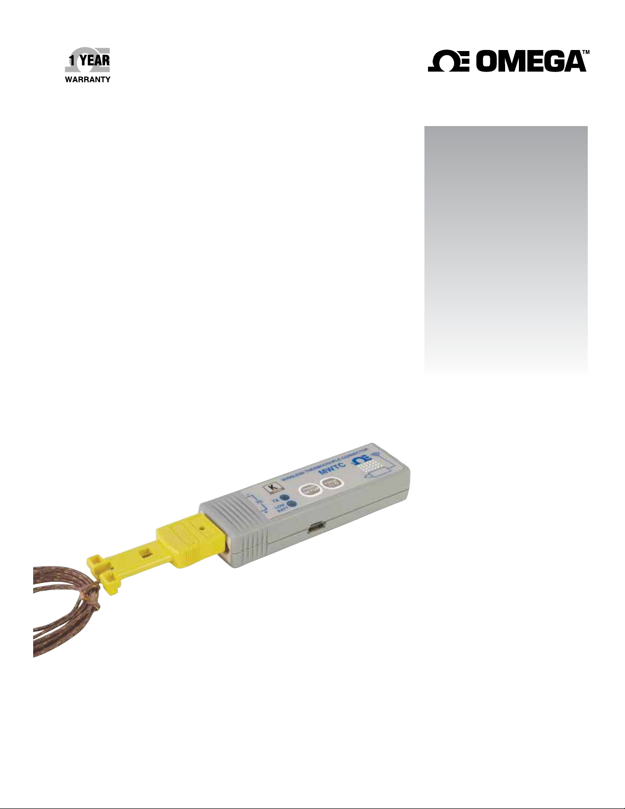
The Smart Connector
ireless Thermocouple/ Connector/
W
Transmitter/ Logger and Receivers
Page 2

omega.com [email protected]
Servicing North America:
U.S.A. Omega Engineering, Inc.
Headquarters: Toll-Free: 1-800-826-6342 (USA & Canada only)
Customer Service: 1-800-622-2378 (USA & Canada only)
Engineering Service: 1-800-872-9436 (USA & Canada only)
Tel: (203) 359-1660
e-mail: [email protected]
Fax: (203) 359-7700
For Other Locations Visit omega.com/worldwide
The information contained in this document is believed to be correct, but OMEGA accepts no liability for any errors it contains, and reserves
the right to alter specifications without notice.
Page 3

MTWC/MWTC-D Series - The Smart ConnectorTM
Wireless Thermocouple/Connector/Transmitter/Logger & Receivers
Table of Contents
Section Page
Section 1 Introduction ......................................................................................... 1-1
1.1 Precautions ................................................................................................ 1-1
1.2 Safety Warnings and IEC Symbols ........................................................ 1-1
1.3 Product Labeling ....................................................................................... 1-2
1.4 Statement on FCC and CE Marking ....................................................... 1-3
1.5 General Description & System Components ........................................ 1-3
Section 2 Hardware ............................................................................................. 2-1
2.1 Package Inspection ................................................................................... 2-1
2.2 Included Items .......................................................................................... 2-1
Section 3 Software ............................................................................................... 3-1
3.1 Getting Started .......................................................................................... 3-1
3.2 Software Installation ................................................................................ 3-1
3.3 USB Driver Installation ............................................................................ 3-4
3.4 MWTC Connector/Transmitter Setup Utility Program ..................... 3-6
3.5 TC-Central Measurement and Recording Program ............................ 3-6
3.6 Charting Tab ............................................................................................ 3-10
3.7 Charting Options .................................................................................... 3-12
3.8 Data Logging Tab ................................................................................... 3-14
3.9 Menu Tabs ............................................................................................... 3-16
Section 4 Transmitter/Connector Operation .................................................. 4-1
4.1SetupandConguration ......................................................................... 4-2
4.2 Mounting, Installation and Antenna Connection .............................. 4-10
4.3 Thermocouple Connections .................................................................. 4-13
4.4 Battery Installation or Replacement ..................................................... 4-14
Section 5 Receiver Operation ............................................................................ 5-1
5.1 Mounting and Installation ....................................................................... 5-2
Section 6 System Operation ............................................................................... 6-1
6.1 Introduction ............................................................................................... 6-1
6.2 RF Communication Basics ...................................................................... .6-1
6.3 Basic System Overview ............................................................................ 6-1
6.4 Connector/Transmitter Operation ........................................................ 6-2
6.5 Receiver Operation ................................................................................... 6-3
6.6 Environment/Operating Conditions ..................................................... 6-4
6.7 Determining and Maximizing Range .................................................... 6-5
6.8 Antenna Basics .......................................................................................... 6-7
6.9 Antenna Placement .................................................................................. 6-7
6.10 Factory Preset Values ............................................................................. 6-8
6.11 Transmit Rate vs. Battery Life ............................................................... 6-8
i
Page 4

MTWC/MWTC-D Series - The Smart ConnectorTM
Wireless Thermocouple/Connector/Transmitter/Logger & Receivers
Section 7 Troubleshooting ................................................................................. 7-1
7.1 Connector/Transmitter Troubleshooting ............................................. 7-1
7.2 Receiver Troubleshooting ........................................................................ 7-1
7.3 LED Indications vs Operation ................................................................ 7-1
Section 8 Service and Calibration ..................................................................... 8-1
8.1 Service and Calibration ............................................................................ 8-1
Section 9 Specications ...................................................................................... 9-1
9.1Connector/TransmitterSpecications(ThermocoupleModels) ...... 9-1
9.2ReceiverSpecications ............................................................................. 9-2
Section 10 Approvals & Regulatory Compliance ........................................ 10-1
10.1 FCC (Domestic Use: USA & Canada) ................................................ 10-1
10.2 International Usage & CE Marking (Pending) ................................ 10-1
10.3 CE Declaration of Conformity (DOC) ............................................... 10-1
10.4 Patent Notice ......................................................................................... 10-2
ii
Page 5

MTWC/MWTC-D Series - The Smart ConnectorTM
Wireless Thermocouple/Connector/Transmitter/Logger & Receivers
Table of Figures
Figure Description Page
Section 1 Introduction
Figure
1-1 IEC Symbols ........................................................................................ 1-1
1-2 TC Connector Front Label ................................................................ 1-2
1-3 Connector Rear Label ........................................................................ 1-2
1-4 MWTC-REC1 Receiver Front and Rear Labels .............................. 1-2
1-5 System Components .......................................................................... 1-3
Section 3 Software
Figure
3-1 Welcome Screen ................................................................................. 3-1
3-2 Select Install Screen ............................................................................ 3-2
3-3 ConrmInstallationScreen .............................................................. 3-2
3-4 License Agreement Screen ................................................................ 3-3
3-5 Installation Complete Screen ........................................................... 3-3
3-6 Welcome To The New Found Hardware Wizard Screen ............ 3-4
3-7 Install Software Automatically Wizard Screen ............................. 3-5
3-8 Completing The New Found Hardware Wizard Screen ............. 3-5
3-9 Channels Tab Menu Screen .............................................................. 3-6
3-10 TC-Central Program Screen ............................................................. 3-6
3-11 ChannelConguration ......................................................................3-7
3-12 CongurationChannel1 .................................................................. 3-7
3-13 Channel Display Box ......................................................................... 3-8
3-14 Charting Tab Menu Screen ............................................................. 3-10
3-15 Charting Screen ................................................................................ 3-10
3-16 Start Data Logging/Plotting Screen .............................................. 3-10
3-17 Charting Options Screen ................................................................. 3-12
3-18 Data Log TAB Screen ...................................................................... 3-14
3-19 Data Logging Screen ........................................................................ 3-14
3-20 Start Data Logging/Plotting Screen .............................................. 3-14
3-21 File Menu Tab ................................................................................... 3-16
3-22 View Menu Tab ................................................................................ 3-17
3-23 Tools Menu Tab ................................................................................ 3-18
Section 4 Connector Operation
Figure
4-1 MWTC Overall Dimensions ............................................................. 4-1
4-2A Transmitter Programming Connection .......................................... 4-2
4-2B Transmitter Programming Connector with Cable Installed ........ 4-2
4-3 Setup Mode ......................................................................................... 4-4
4-4 Launch Setup Utility Program ......................................................... 4-4
4-5 Welcome to Universal Wireless Screen .......................................... 4-5
4-6 Setup the Transmitter Screen ........................................................... 4-5
4-7 Connect the Transmitter Screen ....................................................... 4-6
4-8 Establish a Link Screen ...................................................................... 4-6
iii
Page 6

MTWC/MWTC-D Series - The Smart ConnectorTM
Wireless Thermocouple/Connector/Transmitter/Logger & Receivers
Section 4 Connector Operation Continued
Figure Description Page
4-9 Choose Options Screen ..................................................................... 4-7
4-10 Data Logging Options Menu ........................................................... 4-7
4-11 Typical Data File ................................................................................ 4-8
4-12 Send Settings to The Transmitter Screen ........................................ 4-9
4-12A LED Indications vs. Operations (MWTC-D) ................................ 4-10
4-13 Mounting Bracket Installation ....................................................... 4-11
4-14 Fresnel Zone ..................................................................................... 4-11
4-15 Thermocouple Connection ............................................................. 4-13
4-16 Recommended Thermocouple Placement .................................... 4-14
4-17 Connector Battery Compartment .................................................. 4-14
Section 5 Receiver Operation
Figure
5-1 Receiver Operation - Model UWTC-REC1 ..................................... 5-1
5-2 Mounting ............................................................................................. 5-2
5-3 Installation .......................................................................................... 5-2
Section 6 System Operation
Figure
6-1 Basic System Overview ..................................................................... 6-1
6-2 Connector/Transmitter Button Operation ..................................... 6-2
6-3 Transmit and Low Battery Lights .................................................... 6-3
6-4 Receiver Indicator Lights .................................................................. 6-3
6-5 Determining Maximum Range ........................................................ 6-5
6-6 Operation In Buildings ...................................................................... 6-6
6-7 Horizontal Antenna Placement ....................................................... 6-7
6-8 Vertical Antenna Placement ............................................................. 6-8
Section 7 Troubleshooting
Figure
7-1 LED Indications vs. Operations (MWTC-D) .................................. 7-1
iv
Page 7
Section 1 - Introduction
Please read this manual completely before installing and operating your wireless
connector/transmitter and receiver system. It’s important to read and follow all
notes, cautions, warnings and safety precautions before operating this device.
“Device” refers to your connector/transmitter or receiver unit.
1.1 Precautions
• This device is not designed for use in any medical or nuclear applications.
•Donotoperatethisdeviceinammableorexplosiveenvironments.
• Never operate with a power source other than the one recommended in this
manual.
• This device has been designed for dry, moisture free indoor applications only.
• Do not operate this device outside the recommended use outlined in this
manual. Any change made to the unit without the manufacturer’s approval
could void the user’s authority to operate the equipment.
•Noco-locationwithotherradiotransmittersisallowed.Bydenition,
co-location is when another radio device or it’s antenna is located within
20 cm of your connector/transmitter and can transmit simultaneously with
your MWTC unit.
Introduction
1
• Never install and/or operate your MWTC connector/transmitter closer than
20 cm to nearby persons.
• Never use your MWTC connector/transmitter as a portable device. Your unit
has been designed to be operated in a permanent installation only.
There are no user serviceable parts inside your device. Attempting to repair or service
your unit may void your warranty:
1.2 Safety Warnings and IEC Symbols
This device is marked with international safety and hazard symbols in
accordance with IEC standards. It is important to read and follow all precautions
and instructions in this manual before operating or commissioning this device as
it contains important information relating to safety and EMC. Failure to follow
all safety precautions may result in injury and or damage to your device. Use of
thisdeviceinamannernotspeciedwillvoidyourwarranty
IEC symbols Description
Caution, refer to accompanying documentation
NOTE:
EU’s Waste Electrical and Electronic Equipment
Compliance
Figure 1-1. IEC Symbols
1-1
Page 8
1
Introduction
1.3 Product Labeling
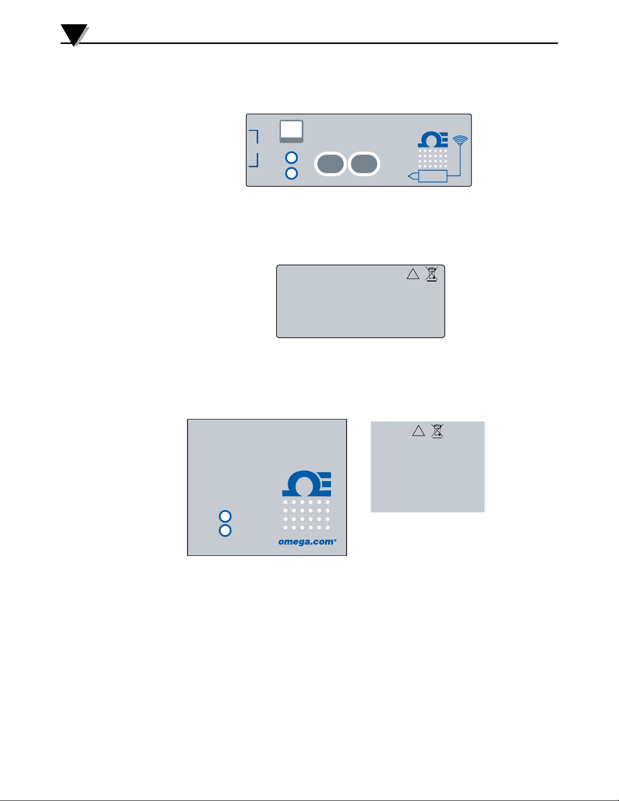
1.3.1 Connector Front Label
–
TC
TX
LOW
+
BATT
WIRELESS THERMOCOUPLE CONNECTOR
TYPE
PRESS
SETUP
MWTC
PRESS
I / O
Figure 1-2. TC Connector Front Label
1.3.2 Connector Rear Label
FCC ID: WR3-MWTC-2
IC:8205A-MWTC2
This device complies with Part 15 of the FCC rules.
Operation is subject to the following two conditions:
1) This device may not cause harmful interference;
2) This device must accept any interference received,
including interference that may cause undesired
operation.
OMEGA ENGINEERING, INC.
Stamford, CT 06907
PATENTS & PATENTS PENDING
omega.com
Made in U.S.A.
Figure 1-3. Connector Rear Label
1.3.3 MWTC-REC1 Receiver Front and Rear Labels
®
!
®
MWTC SERIES
WIRELESS RECEIVER
®
TX
PWR
Front Label
Figure 1-4. UWTC-REC1 Receiver
!
This device complies with Part 15
of the FCC rules. Operation is subject
to the following two conditions:
1) This device may not cause harmful
interference; 2) This device must
accept any interference received,
including interference that may cause
undesired operation.
OMEGA ENGINEERING, INC.
Stamford, CT 06907
omega.com
Made
in U.S.A.
Rear Label
®
1-2
Page 9
1.4 Statement on FCC and CE Marking
1.4.1 FCC Marking
FCC ID: WR3-MWTC-2
This device complies with Part 15 of the FCC rules. Operation is subject to the
following two conditions: 1.) This device may not cause harmful interference.
2.) This device must accept any interference received, including interference that
may cause undesired operation.
1.4.2 CE Marking
It is the policy of OMEGA
®
to comply with all worldwide safety and EMI/
EMCregulationsthatapply.OMEGAisconstantlypursuingcerticationofits
products to the European New Approach Directives. OMEGA will add the CE
marktoeveryappropriatedeviceuponcertication.Foradditionalinformation
see Section 10 - Approvals & Regulatory Compliance.
1.5 General Description & System Components
1.5.1 General Description
Introduction
1
Your Wireless Thermocouple/Connector Series features stand-alone, compact,
battery powered wireless connectors that transmit their readings back to a
host receiver up to 90 m (300’) away. Each thermocouple unit is factory set to
work as a type J, K, T, E, R, S, B, N or C calibration connector. When activated
the connector will transmit readings continuously at a pre-set time interval
that was programmed by the user during the initial setup. Each unit measures
and transmits: Process Input Reading, Connector Ambient Temperature, RF
Signal Strength and Battery Condition to the host and is displayed on the PC
screen in real time using the provided software. When used with host receiver
model MWTC-REC1 data from up to 48 wireless connectors can be received
and displayed. Each unit includes free software that converts your PC into a
strip chart recorder or data logger so readings can be saved and later printed or
exportedtoaspreadsheetle.
MWTC-D is a wireless thermocouple connector/data logger. It can record
up to 65400 process temperature data points or 32,700 process and ambient
temperature data points locally. The recorded data can be downloaded to PC
using the direct USB connection.
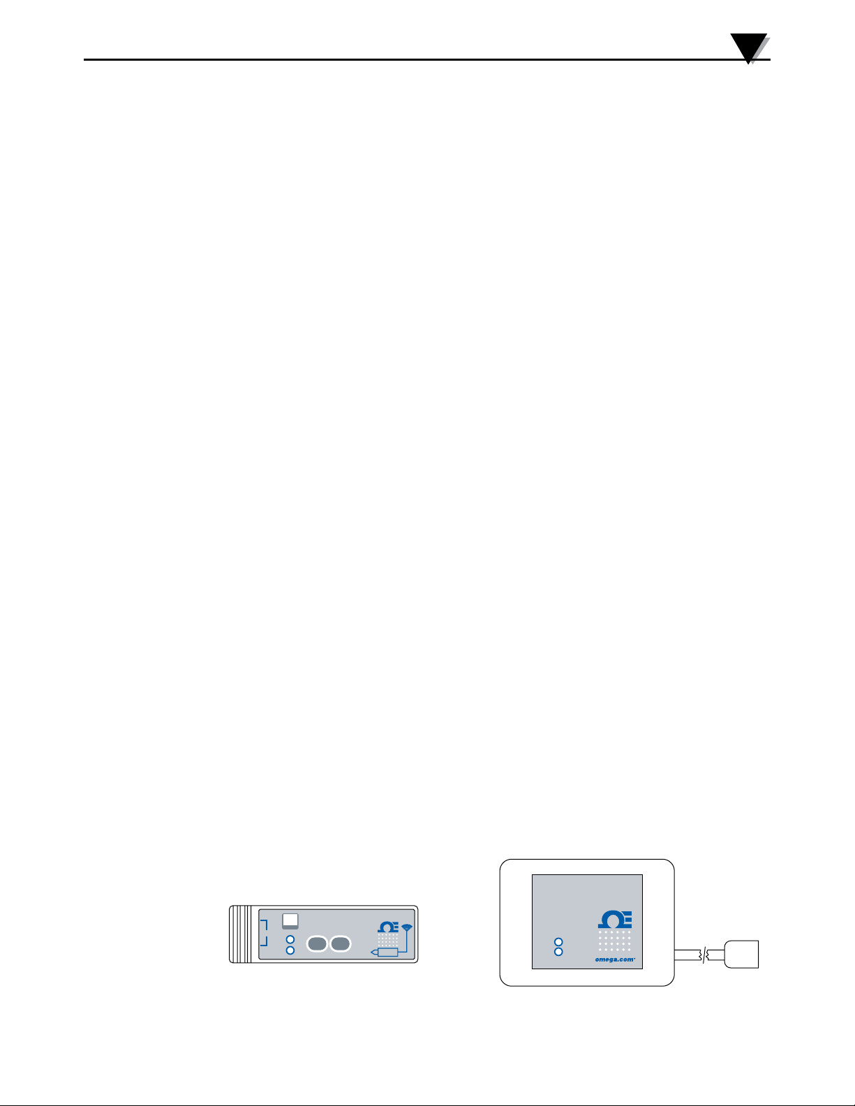
1.5.2 System Components
USB RECEIVER
CONNECTOR/TRANSMITTER
–
+
WIRELESS THERMOCOUPLE CONNECTOR
TYPE
TC
TX
PRESS
SETUP
LOW
BATT
MWTC
PRESS
I / O
®
MWTC SERIES
WIRELESS RECEIVER
TX
PWR
Figure 1-5. System Components
®
1-3
Page 10
2
Hardware
Section 2 – Hardware
It is important that you read this manual completely and follow all safety
precautions before operating this instrument.
2.1 Package Inspection
Remove the packing list and verify that you have received all your equipment. If
you have any questions about the shipment, please call our Customer Service
Department at 1-800-622-2378 or 203-359-1660. We can also be reached on the
Internet at omega.com, e-mail: [email protected]. When you receive the
shipment, inspect the container and equipment for any signs of damage. Note
any evidence of rough handling in transit. Immediately report any damage to
the shipping agent.
The carrier will not honor any damage claims unless all shipping material is saved for
inspection. After examining and removing contents, save packing material and carton
in the event reshipment is necessary.
NOTE:
2.2 Included Items
The following items are supplied in the box.
With Model MWTC Connector/Transmitter:
• 1 Connector/Transmitter
• 1 Type-K Thermocouple Sensor (Omega No. SC-GG-K-30-36-PP)
(MWTC models only)
• 1 Standard (AAA) 1.5V Lithium Battery, (Omega No. MWTC-A-BATT) for use
with Model MWTC.
• 1 Mounting Bracket Kit
• 1 Micro-B USB Cable for MWTC-D (Data Logger)
With Model MWTC-REC1, MWTC-REC5, or MWTC-REC6 Receiver:
• 1 Receiver Device
• 1 MWTC Series User’s Manual (M-4721)
• 1 USB Interface Cable
• 1 TC-Central User Software CD
• 4 Rubber Enclosure Feet
2-1
• 1 MWTC Transmitter Programming Cable
Page 11
Section 3 – Software
3.1 Getting Started
ThefollowingprogramlesareincludedontheMWTCUserSoftwareCD
suppliedwithyourReceiver.Theselescanalsobedownloadedfromthe
omega.com website should you misplace your CD.
• MWTC Connector/Transmitter Setup Utility Program
• TC-Central Measurement and Data Logging Program
3.2 Software Installation
3.2.1 System Requirements
Your PC should meet the following minimum requirements:
• Pentium Class processor
• Hard Drive Space: 210 meg
• Ram: 256 meg or higher
• 1 Available USB Port
• 1 CD-ROM Drive
• Windows 2000, XP, Vista (32bit), or 7 Operating System
Software
3
3.2.2 Software Installation
Insert the MWTC Series User CD that was included with your receiver unit
into the CD-ROM drive on your PC. Your system should begin the installation
process automatically. If the software installation does not start automatically
please see the “Troubleshooting” Section 7.
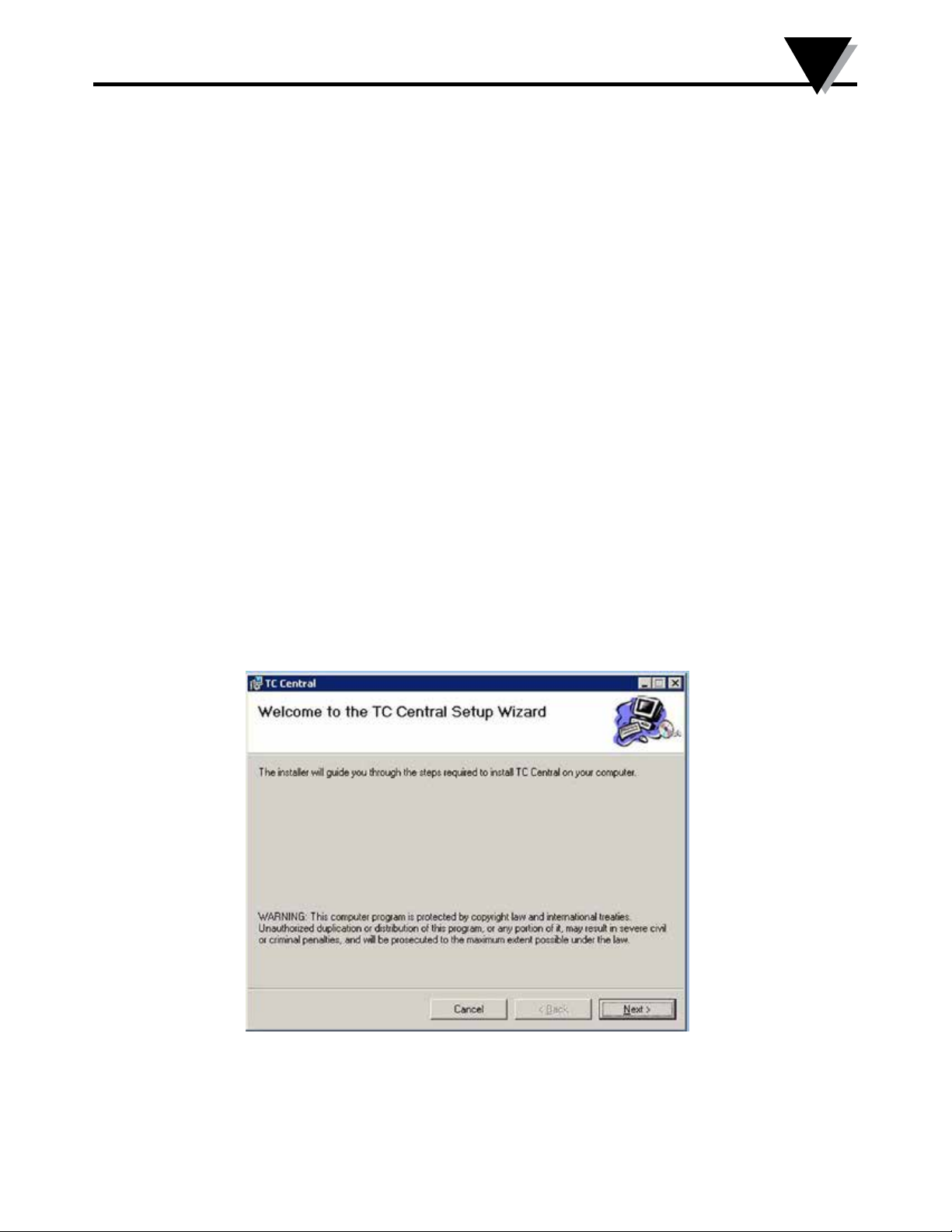
Figure 3-1.
Welcome Screen
This welcome screen should be visible on your computer screen. To continue
with installing the program click the “Next >” button.
3-1
Page 12
3
Software
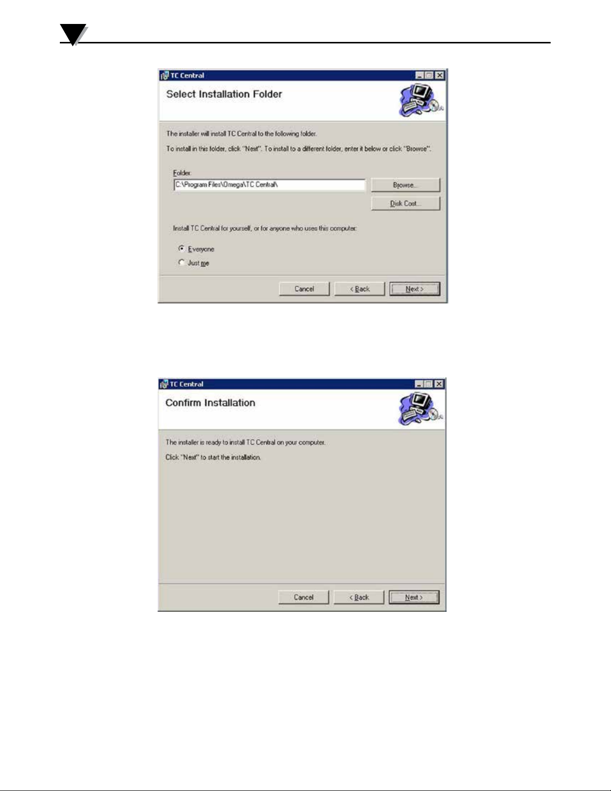
Figure 3-2.
Select Install Screen
Fromthisscreenyouselectthefolderwereyouwanttheprogramlesinstalled
on your PC. The default setting will install the software under your “Program”
folders in a new folder named “Omega” To continue with installing the program
click the “Next >” button.
“Program” folders in a new folder named “Omega” To continue with installing
the program click the “Next >” button.
Figure 3-3.
Conrm Installation
Screen
3-2
The setup wizard now has all the information to complete the installation of the
software on your PC. To continue with installing the program click the “Next >”
button.
Page 13
Software
3
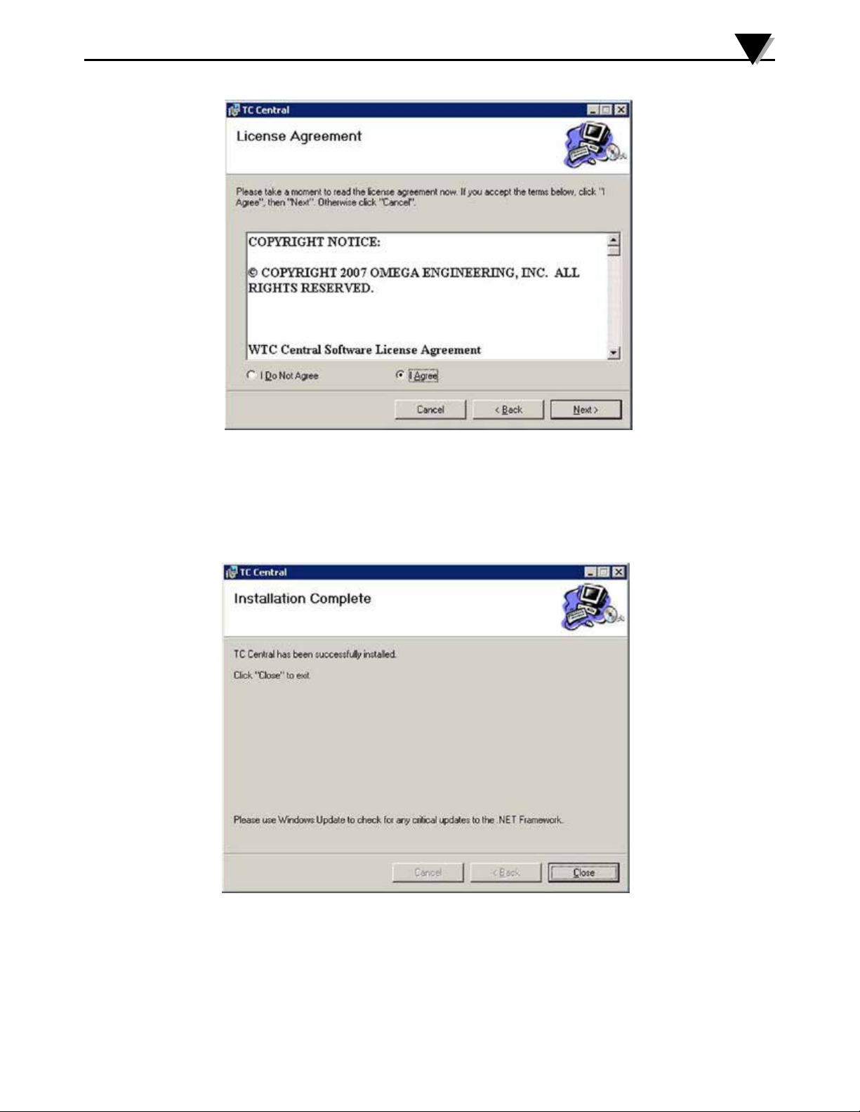
From this screen you must select “Agree” to continue installing your program.
After making your selection click the “Next >” button. The setup wizard will
now install the software.
Figure 3-4.
License
Agreement Screen
Congratulations! You have just successfully installed the TC-Central Program on
your PC. To end installing the program and close the setup wizard click the
“Close” Button.
From this screen you must select “Agree” to continue installing your program.
After making your selection click the “Next >” button. The setup wizard will
now install the software.
Figure 3-5.
Installation
Complete Screen
Congratulations! You have just successfully installed the WTC Central Program
on your PC. To end installing the program and close the setup wizard click the
“Close” button.
3-3
Page 14
3
Software
3.3 USB Driver Installation
To install the USB software drivers that are required for your MWTC system
components to operate correctly follow these procedures.
You need to have the TC-Central User Software CD that was supplied with your
receiver loaded into the CD drive on your PC.
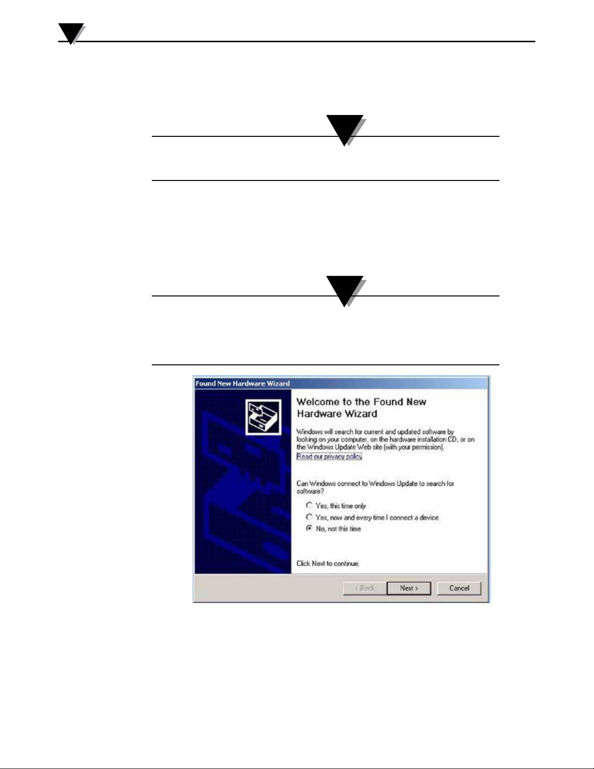
1. Connect your MWTC receiver to your computer with the USB cable
provided in the box with your device. You should get a notice box that
indicates that your computer “Has Found New Hardware”
2. Your computer will then launch the Found New Hardware Wizard.
Follow the instructions indicated on the Wizard boxes and the additional
instructions noted in this manual with each box.
NOTE:
NOTE:
After completing the Found New Hardware Wizard your system will ask that you
repeat this process. This is normal. You should repeat the steps outlined here twice.
After the second driver is installed you should then get the “New Hardware Ready For
Use” notice.
3-4
Figure 3-6. Welcome To The Found New Hardware Wizard Screen
From this box you should check the “No, not at this time” button. Then click the
“Next >” button to continue with the driver installation process.
Page 15
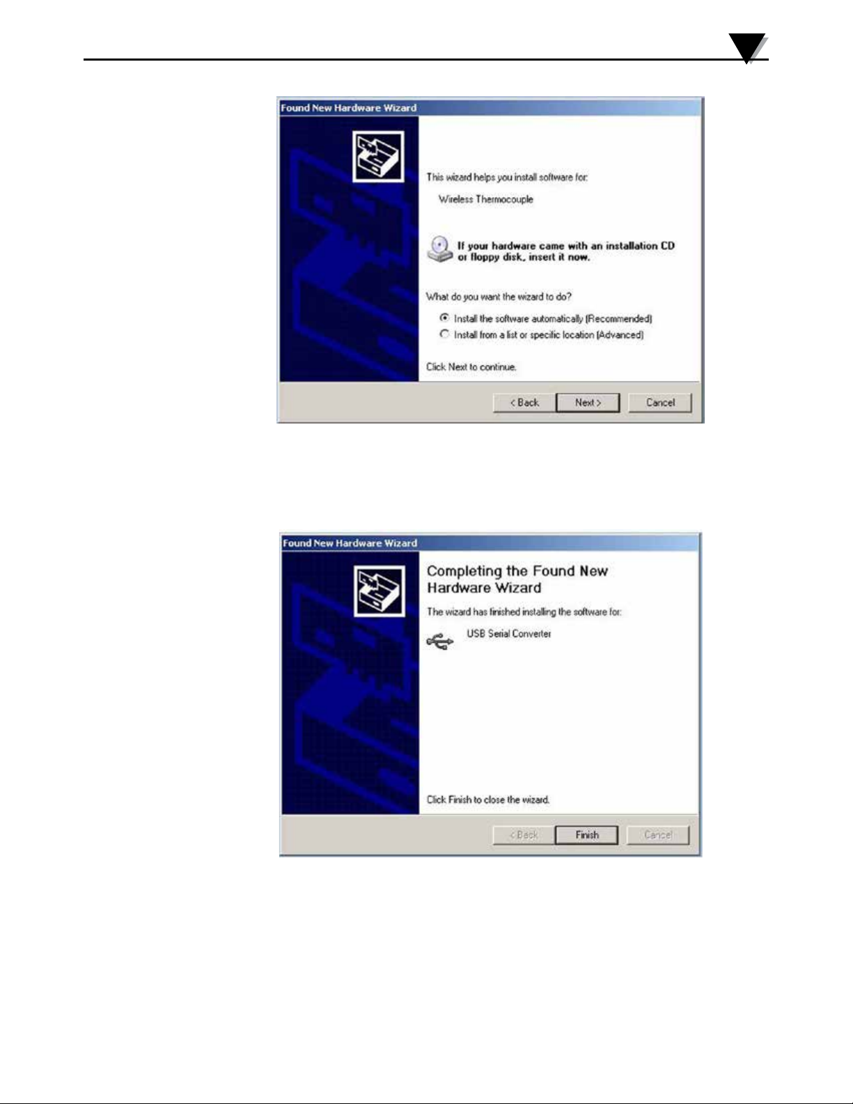
Figure 3-7. Install Software Automatically Screen
Software
3
Next, check the “Install the software automatically” button. Then click the
“Next>” button to continue.
Figure 3-8. Completing The Found New Hardware Wizard Screen
This screen will be displayed to indicate that the software drivers have been
installed. You should click the “Finish” button to complete the process.
3-5
Page 16
3
Software
3.4 MWTC Connector/Transmitter Setup Utility Program
This utility is used to program your connector/transmitter for the following
operating parameters: Channel Number, Sample Rate, and data logging
(MWTC-D). For complete instructions on using this program please see Section 4.
3.5 TC-Central Measurement and Recording Program
To launch the TC-Central program on your PC begin by accessing the
“Programs” list under your “Start Menu” Next, scroll through the list of
programfolderstondthe“TC-Central”folder.Insidethe“TC-Central”folder
click on the “TC-Central” program link. This will start the software running.
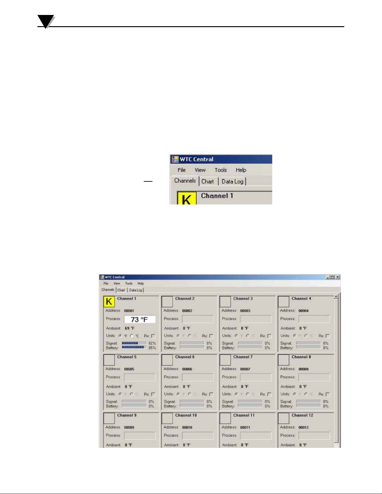
3.5.1 Channels TAB Menu
CHANNELS
TAB
Figure 3-9. Channels TAB Menu Screen
Channels Tab
When TC-Central starts up, the “Channels” tab is displayed. This view allows
you to see temperatures and properties for up to 12 connector/transmitter at one
time
3-6
Figure 3-10. TC-Central Program
Page 17
Software
3
This is a partial view of the TC-Central Program in operation. You will not have
any blocks receiving data until you have programmed and placed into operation
your connector/transmitters.
3.5.2 Setting up the TC-Central Program
Before you can make wireless measurements with your connector/transmitter
theTC-Centralsoftwaremustbeconguredproperly.Thefollowingsteps
outline how to setup your program.
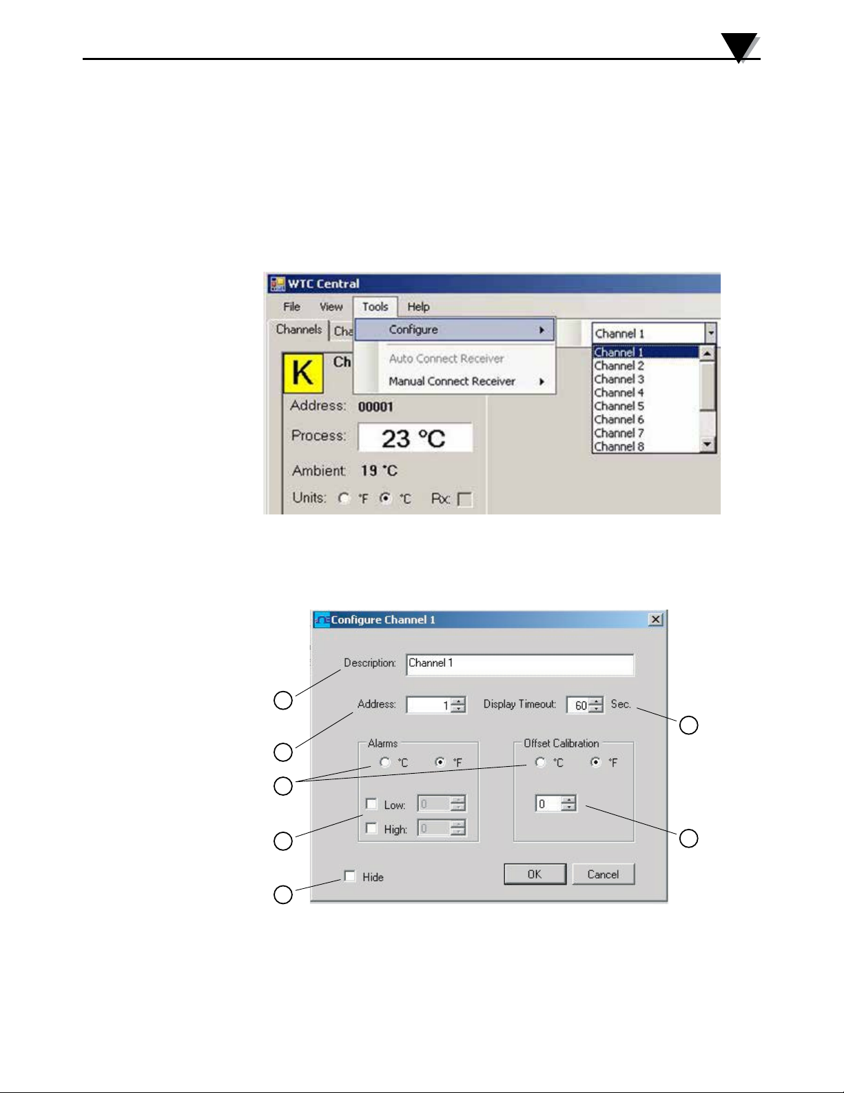
3.5.3 Channel Conguration
Figure 3-11. Channel Conguration
Fromthe“Tools”pull-downmenuselect“Congure”….”Channel1”.Thiswill
open the program settings table were you can make selections on how you want
your system to operate.
1
3
2
5
4
6
Figure 3-12. Conguration Channel 1
7
Description Field
➀
In the Description Field you can type a reference name that is associated with the
location or process being measured by the connector/transmitter for address.
Example.. “Test Chamber 1”
3-7
Page 18
3
Software
Address Field
②
Here you must set an address number into this box that corresponds to a
matching Connector/Transmitter unit that you are using in your system. For
the system to work correctly each Connector/Transmitter must have a number
programmedthatisdierentthenotherunitsinyoursystem.Clickwithyour
mouse on the “Up” and “Down” buttons to advance to a higher or lower
address number.
Display Timeout
③
The Display Timeout setting is used to set how long you want the unit to
continue showing the last reading data when communication between the
Connector/Transmitter and receiver has been lost. Make sure not to set
this value to a time less than the current sample rate programmed into the
Connector/Transmitter or you will never receive and or display any readings.
Low Alarm / High Alarm
④
When the “High” or “Low” Alarm box is checked the alarm feature becomes
active. Click with your mouse on the “Up” and “Down” buttons to advance to
a higher or lower setting. The displayed temperature reading will change to
RED digits and begin blinking to indicate that the process temperature has gone
below the low alarm or exceeded the high alarm value.
°C or °F
⑤
Selectingthe°Cor°Fbuttonwillconguretheparticularboxtodisplayreadings
in the desired units of measurement.
Hide
⑥
Whenthe“Hide”boxischeckedtheparticularboxthatyouareconguring
will become inactive and will not show up on the screen when running the
TC-Central program. This is used to remove unused boxed when less than 12
Connector/Transmitter units are being used.
Sensor Oset
⑦
2
1
3
4
5
6
7
8
9
3-8
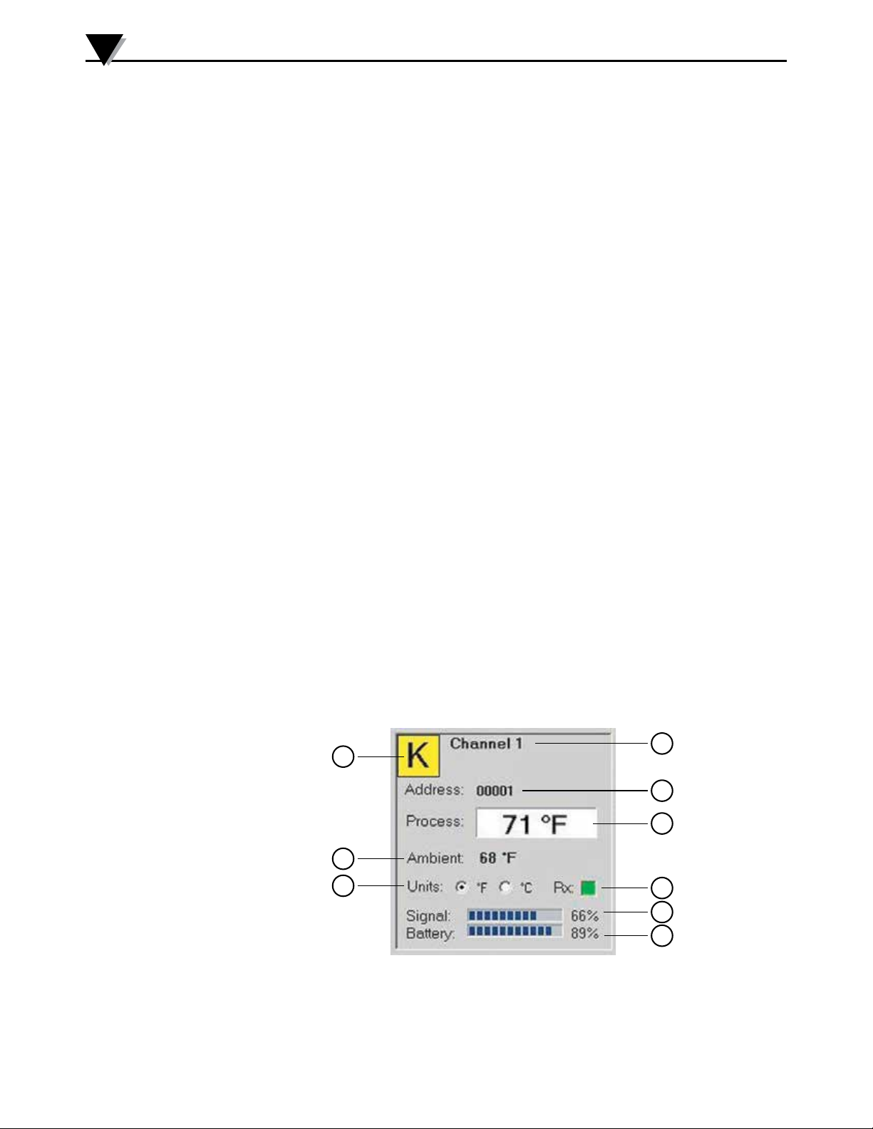
Figure 3-13. Channel Display Box
Thermocouple Type
①
This box indicates the type of thermocouple sensor that your connector/
transmitter is programmed to operate with. As a default the thermocouple color
Page 19

Software
codes have been set to the ANSI color codes. You can change these to IEC color
codes, see section 3.5.2
Reference
②
This location will display the reference name you typed into the “Description”
eldwhenthisboxwascongured.Thiscanbechangedatanytime
Address
③
Thenumberdisplayedhereistheaddressnumberyouspeciedwhenthis
displayboxwascongured.Thisnumbermustmatchthecorresponding
Connector/Transmitterthathasthesamenumberspeciedoryoursystemwill
not receive the correct data readings.
Process
④
This is the actual process temperature reading that is being measured by your
thermocouple or RTD sensor.
Ambient
⑤
This is the actual ambient temperature connector inside the body of your
Connector/Transmitter. If the unit is exposed to temperatures outside the limits
speciedinthismanualthereadingwillbegintoblinkandthedigitswillturn
red to provide a visual warning.
3
Units
⑥
Units of measurement setting can be changed from here without going into the
mainchannelcongurationmenu.Justclickwithyourmouseontothedesired
°C or °F button to make a change.
RX
⑦
The “RX” indicator box will display a green light that blinks each time the
receiver acquires data from the corresponding connector transmitter.
Signal
⑧
This percentage bar graph indicates the radio signal strength being received by
the receiver. This should be used as guidance when installing your system to
help determine the best location and positioning of your equipment.
Battery
⑨
This percentage bar graph indicates the amount of remaining usable available
power the battery installed in the Connector/Transmitter has left to operate
normally.
3.5.4 Changing Thermocouple Color Codes.
By default the setting for thermocouple color code is the American National
Standards Institute (ANSI) standard. You can change the default setting to the
International Electrotechnical Commission (IEC) standard here under this menu
in the TC-Central software.
3-9
Page 20
3
Software
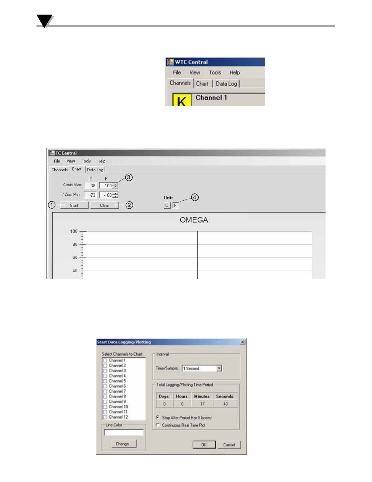
3.6 Chart Tab
CHART TAB
Figure 3-14. Chart TAB Menu Screen
The “Chart” tab allows you to start, stop and view real-time data from the
transmitters in a screen plot that you can save and print.
3-10
Figure 3-15. Charting Screen
Start Button
①
The “Start” button will open the dialog box shown below. This box allows you
to select one or more channels to be plotted. Click the checkbox next to the
channel(s) number you want to include in your plot.
Figure 3-16.
Start Data
Logging/
Plotting
Screen
Page 21

Software
Line Color
Youcanchangethecolorspeciedforeachchannel’sline.Clickthe“Change”
button to select a new color for the Channel selected.
Interval
The total logging time is displayed for the interval setting selected. In general,
the interval should normally be set to a value equal to or greater than the same
sample time you programmed into the corresponding connector/transmitter for
that channel.
You can choose to have the data logging/chart recording session end after
1000 data points, or have the session run continuously. After 1000 data points
have been collected in the continuous mode, the oldest data point is shifted out
on the left, and the newest data point is added to the right. Data will continue to
be collected and displayed until you click on the “Stop” button above the chart.
If you click the OK button, the data logging session will start, and “Recording
Data”willashinthestatusbar.The“Start”buttonabovethechartwillchange
to “Stop”, indicating that if you click it again, the logging session will be
terminated.
3
You can also start or stop a data recording session from the File menu. Once
datahasbeencollected,youcansaveitina(*.csv)(commaseparatedvalues)le
and open it in Microsoft Excel for further analysis. It is recommended that you
“Save As” in Excel as a Microsoft Excel Workbook (*.xls). If you do not modify
the(*.csv)versionofthele,youcanopenitfromTCCentral’sFilemenu,and
display it in the chart and data log.
Clear Button
②
The “Clear” button will delete all data from the chart and the data log.
Y Axis Control
③
The Y Axis Min and Y Axis Max controls allow you to adjust the viewable range
of temperatures to suit your particular application. The narrower the range
between min and max, the more detail can be seen on the chart.
C or F Button
④
The C or F button allows you to change the units of degrees displayed on the
chart, and on the data logging.
3-11
Page 22
3
Software
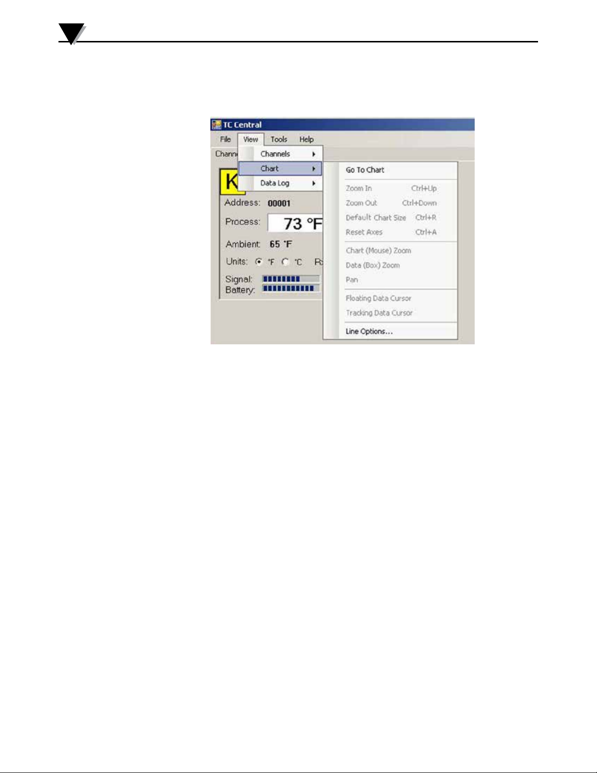
3.7 Charting Options
You can access all of the charting options that are available by opening the chart
option menu found under the “View” Tab. See below.
Figure 3-17. Charting Options Screen
Zoom In/Zoom Out
Allow you to change the size of the chart on the screen. You can also use the
Control-Up Arrow and Control-Down Arrow keys as well.
Default Chart Size
Returns the chart to its normal size (after zooming or panning), and places the
title and legend in their normal positions.
Reset Axes
ResetAxeswilleectivelycanceltheresultsofaDataZoomandreturntheaxes
back to their original dimensions, but will not change the size of the chart.
Chart (Mouse) Zoom
Perform the same function as mentioned above, by moving the mouse up or
down, or rolling the mouse wheel.
Data (Box) Zoom
When checked, you can use the mouse to click and drag a rectangle around a
line of data to magnify that portion of the chart. The chart size will remain the
same, but the axes will be expanded as well and the data line(s) to allow viewing
more detail. You can close either of the axis scroll bars by clicking on the Red
button of each scroll bar.
3-12
Pan
Allows you to move the chart as well as the title and legend around on the
screen. If the Pan item is checked, you can still use the mouse wheel to zoom in
and out, while holding the left button down to move the chart as desired.
Page 23

Software
3
ResetAxeswilleectivelycanceltheresultsofaDataZoomandreturntheaxes
back to their original dimensions, but will not change the size of the chart.
Floating Cursor
When checked, will display a crosshair type cursor that you can move with the
mouse. You can use the Floating Cursor to pinpoint a particular temperature
and time. The status bar displays the data point number, the time, and the
temperature, where the crosshairs meet. If the horizontal cursor line is touching
a data plot line, the corresponding channel number is also displayed in the status
bar.
Tracking Cursor
When checked, will perform similarly to the Floating Cursor, except that you can
specify a channel for the horizontal cursor line to lock on to. This channel is also
displayed in the status bar. With this option enabled, you can move the mouse
left and right without regard to up and down, and the horizontal cursor will
remain pointing to the line (channel) you specify. Assuming you have more than
one channel plotted on the chart, you can switch tracking to another channel
by moving the mouse over the data line of that channel until the mouse cursor
becomesahandwithapointingnger.Ifyouleft-clickatthispoint,theTracking
Cursor will track that line. You can also change the channel of the Tracking
Cursor from the chart’s context menu, Tracking Cursor menu item combo box.
The same option is also available in the View Chart menu in the main menu bar
Line Options
Allows you to select which channel(s) you want to display, and/or change the
color of each channel data line. This allows you to limit your view to either a
single channel, or a selected two or more channels for comparison, instead of
having all twelve channels displayed at once.
3-13
Page 24
3
Software
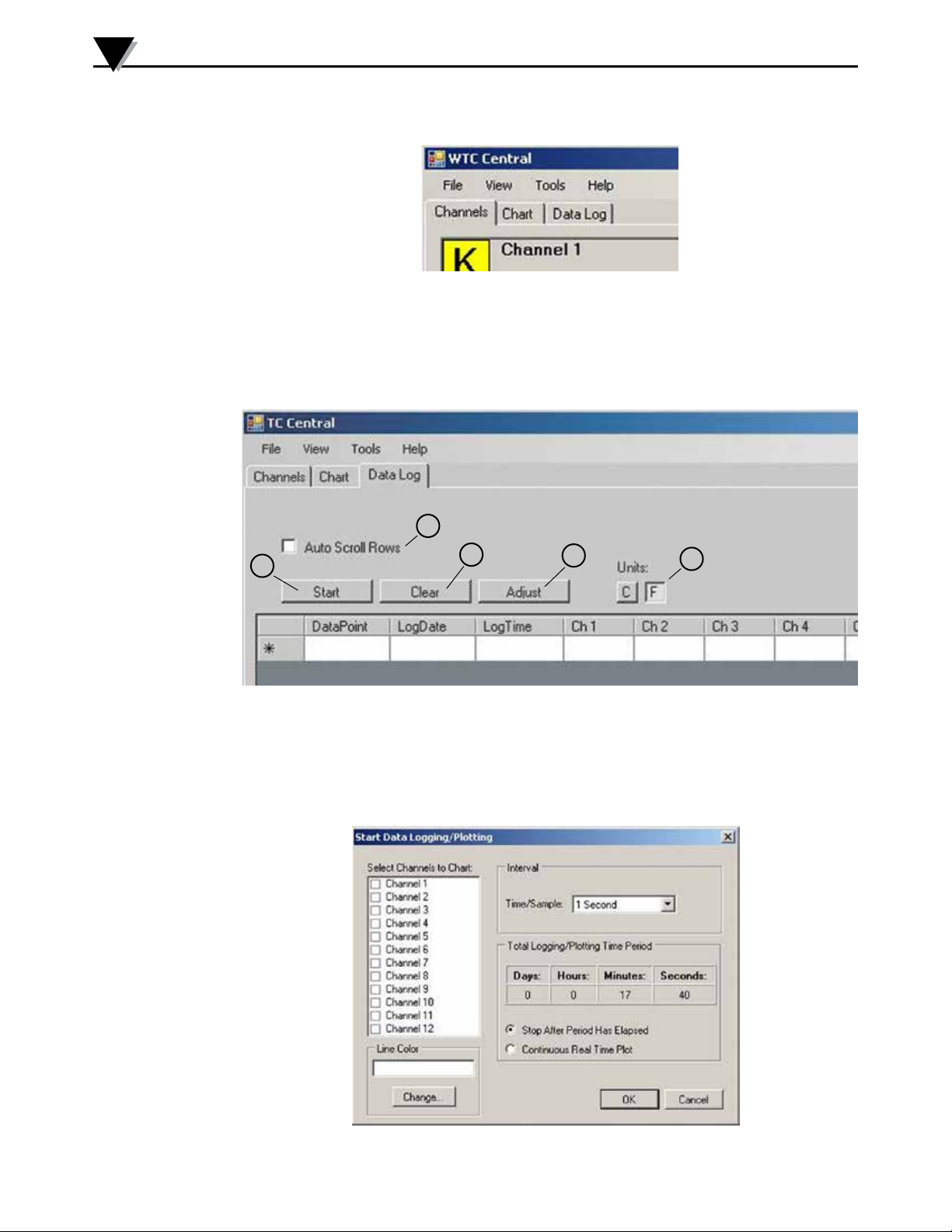
3.8 Data Log Tab
DATA LOG TAB
Figure 3-18. Date Log TAB Screen
The “Data Log” tab allows you to view received data from a connector/
transmitter in a table format as it is being recorded. This data can be saved and
printed.
5
1
Start Button
➀
2
Figure 3-19. Data Logging Screen
The “Start” button will open the dialog box shown below. This box allows you
to select one or more channels to be plotted. Click the checkbox next to the
channel(s) number you want to include in your plot.
3
4
3-14
Figure 3-20. Start Data Logging/Plotting Screen
Page 25

Software
Line Color
Youcanchangethecolorspeciedforeachchannel’sline.Clickthe“Change”
button to select a new color for the Channel selected.
Interval
The total logging time is displayed for the interval setting selected. In general,
the interval should normally be set to a value equal to or greater than the same
sample time you programmed into the corresponding connector/transmitter for
that channel.
You can choose to have the data logging/chart recording session end after
1000 data points, or have the session run continuously. After 1000 data points
have been collected in the continuous mode, the oldest data point is shifted out
on the left, and the newest data point is added to the right. Data will continue to
be collected and displayed until you click on the “Stop” button above the chart.
If you click the OK button, the data logging session will start, and “Recording
Data”willashinthestatusbar.The“Start”buttonabovethechartwillchange
to “Stop”, indicating that if you click it again, the logging session will be
terminated.
3
You can also start or stop a data recording session from the File menu. Once
datahasbeencollected,youcansaveitina(*.csv)(commaseparatedvalues)le
and open it in Microsoft Excel for further analysis. It is recommended that you
“Save As” in Excel as a Microsoft Excel Workbook (*.xls). If you do not modify
the(*.csv)versionofthele,youcanopenitfromTCCentral’sFilemenu,and
display it in the chart and data log.
Clear Button
②
The “Clear” button will delete all data from the data log.
Adjust Button
③
Resizesthecolumnstothesmallestsizenecessarytotallthedatainthe
columns.
C or F Button
④
The C or F button allows you to change the units of degrees displayed during
the data logging.
Auto Scroll Rows
⑤
The Auto Scroll Rows checkbox causes the data to be scrolled up one line each
time a new row of data is added to the grid.
3-15
Page 26
3
Software
3.9 Menu Tabs
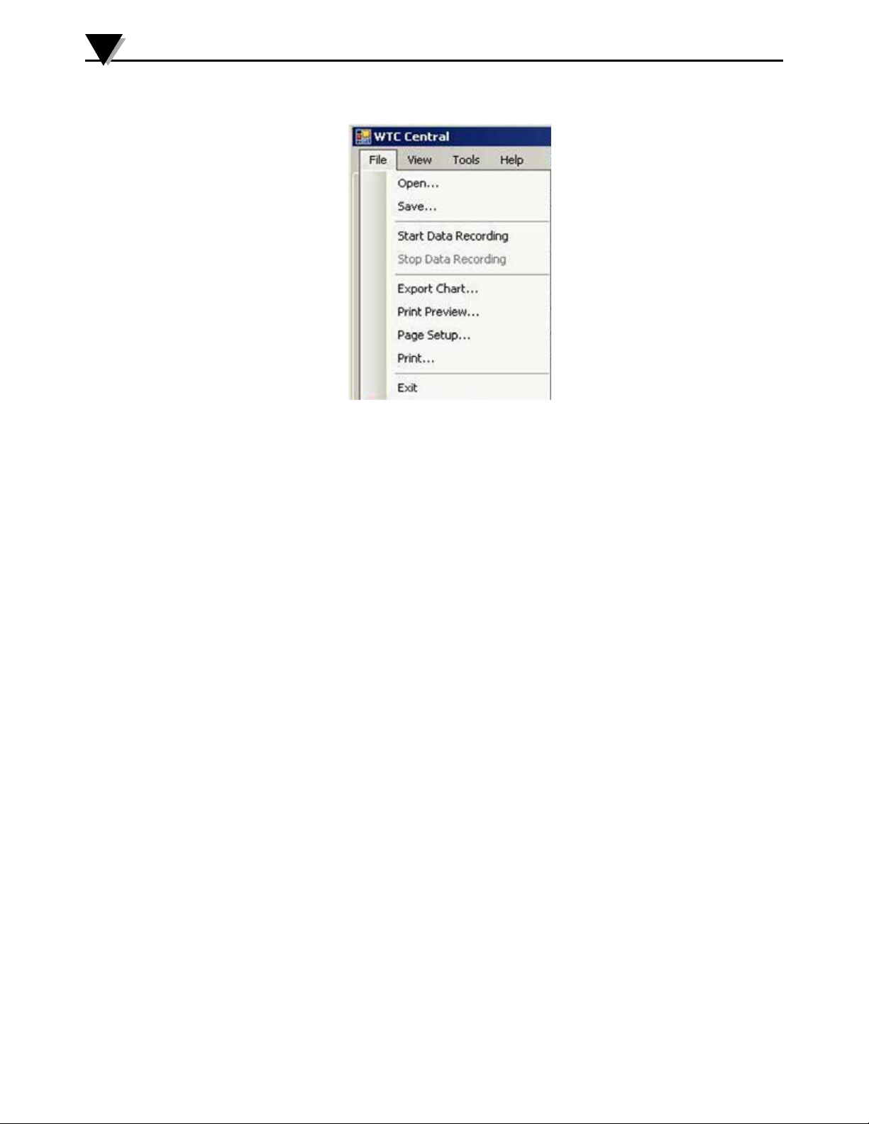
3.9.1 File Menu
Figure 3-21.
File Menu Tab
Open…
Displaysadialogboxwhichallowsyoutochooseadataletoopenanddisplay
onthechartandinthedatalog.Thislemustbealethatwassavedbythe
SavemenuiteminTCCentral.Ifthelehasbeenmodiedexternally,youmay
not be able to open it.
Save…
Displays a dialog box which allows you to save the data currently displayed on
thechartandinthedatalog.Theleformatis(*.csv)(commaseparatedvalues),
which can be opened by Microsoft Excel for further analysis and charting. It
isstronglyrecommendedthatyoudonotmodifythisle,oryoumaynotbe
able to open it again in TC Central. Use Excel’s “Save As” option to save it as a
Microsoft Excel Workbook (*.xls), which you can then modify.
Start Data Recording…
Performs the same function as the Start button on the Chart and Data Log Tabs.
A dialog box is displayed allowing you to select one or more channels to be
plotted and logged by checking the checkbox next to the channel number. You
can also change the color of each channel’s line.
The interval should be set as desired for your particular needs. The total logging
time is displayed for the interval setting selected. In general, the interval should
normally be set to a value equal to or greater than the “Seconds per Sample” you
conguredintothetransmitterusingtheMWTCCongurationWizard.
You can choose to have the data logging/chart recording session end after 1000
data points, or have the session run continuously. After 1000 data points have
been collected in the continuous mode, the oldest data point is shifted out on
the left, and the newest data point is added to the right. Data will continue to
be collected and displayed until you click on the “Stop” button above the chart,
above the Data Log, or select Stop Data Logging from the File menu.
3-16
If you click the OK button, the data logging session will start, and “Recording
Data”willashinthestatusbar.The“Start”buttonabovethechartanddata
log will change to “Stop”, indicating that if you click it again, the logging session
will be terminated.
Page 27
Software
3
Stop Data Logging…
Performs the same function as the “Stop” buttons on the Chart and Data Log
Tabs, by terminating any data logging/plotting session in progress.
Export Chart…
Displays a dialog box that allows you to either save an image of the current chart
on the Chart Tab, or copy it to the clipboard.
Print Preview…
Displays a standard Windows Print Preview dialog, allowing you to view the
item(s) as they would be printed on a printer. You can also print from this
dialog by clicking the printer icon in the upper left corner. If the Channels Tab
is displayed before choosing this option, a screen snapshot of the Channels Tab
will be previewed. If the Chart Tab is displayed before choosing this option, the
current chart image will be previewed. If the Data Log Tab is displayed, the data
table in grid style format will be previewed.
Page Setup…
Displays a standard page setup dialog box which allows you to change the page
orientation, margins, paper size, etc. You can then select the Print Preview menu
to view your changes without printing.
Print…
Displays a standard print dialog box. This allows you to select printers, printer
preferences, page ranges, number of copies, etc. If you click the “Print” button,
thespeciedpage(s)willbesenttotheprinter.Ifyouclickthe“Apply”button,
you can then select the Print Preview menu to view your changes without
printing.
Exit…
Will exits and close the TC-Central program.
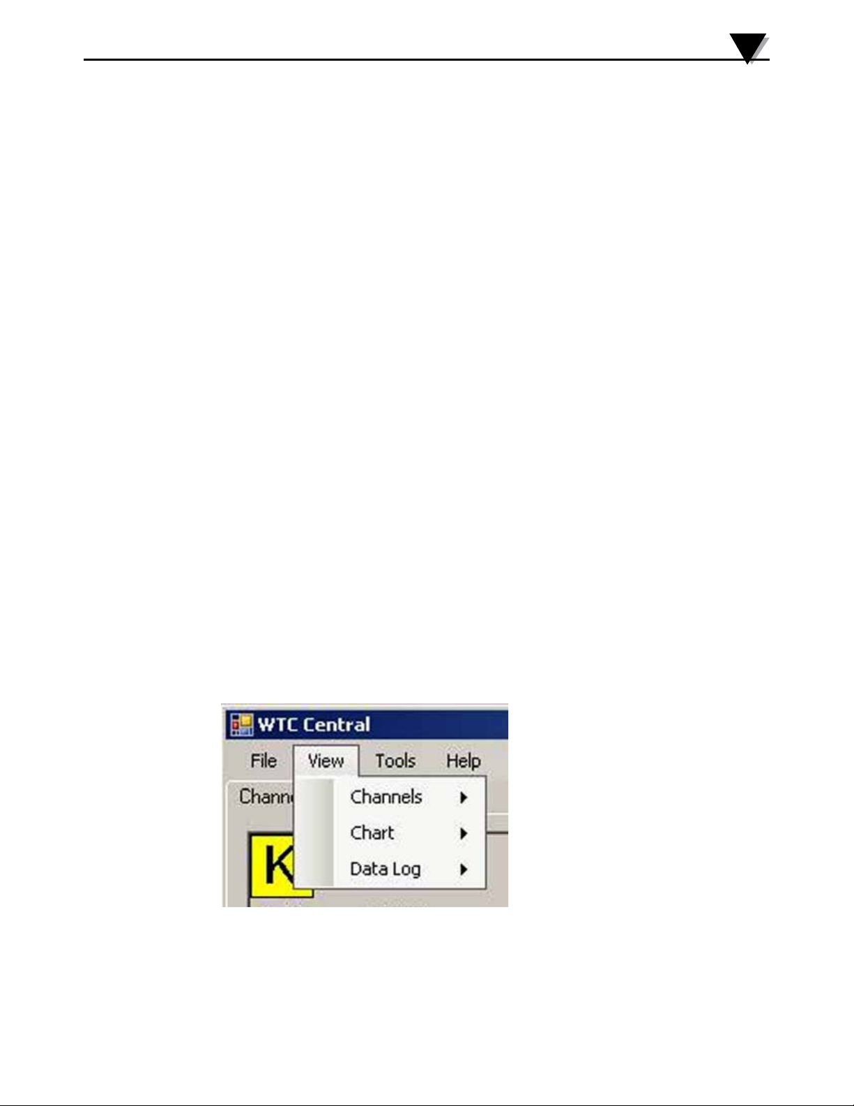
3.9.2 View Menu Tab
Figure 3-22. View Menu
Channels
Performs the same functions as the Channels context menu, except for the
Conguremenuitem.SeeChannelsTABMenu(Section3.9)foranexplanation
of this menu.
3-17
Page 28
3
Software
Chart
Performs the same functions as the Chart context menu. See Chart Tab Menu
(Section 3.6) for an explanation of this menu.
Data Log
Performs the same functions as the “Auto Scroll Rows” checkbox and the
“Adjust” button on the data log. See Data Log Menu (Section 3.8) for an
explanation of these functions.
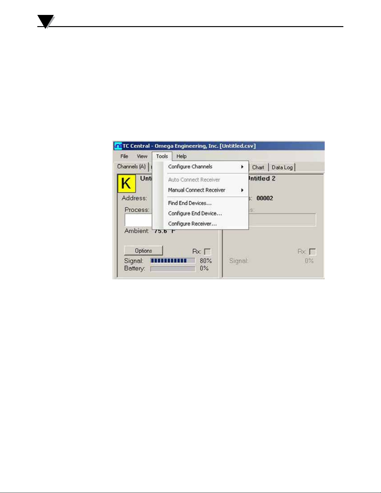
3.9.3 Tools Menu
3-18
Figure 3-23. Tools Menu Tab
Congure
DisplaysthesamedialogboxastheChannelscontextmenu,Conguremenu
item,afteryouselectachanneltocongure.SeeChannelsTababoveforan
explanation of this dialog box.
Auto Connect Receiver
Normally disabled, if you have established communications with a receiver
connected to your PC. If for some reason such as the receiver being replaced
withadierentone,thismenuitemwillbeavailable.Whenselected,TCCentral
will send “+++” to each and every available COM port in an attempt to identify
aportwithareceiverconnectedtoit.IfTCCentralndsareceiver,itwill
performthenecessarycongurationofthereceiveranddisplaytheCOMport
number in Green in the status bar. Even though your receiver is connected via a
USB Cable, the USB drivers installed create a “virtual” COM port, usually a port
number greater than COM4. Once connected, TC Central saves (remembers) the
port number you are using, and will automatically connect to it the next time TC
Central is started.
Page 29

Software
3
Manual Connect Receiver
Is available if you do not want TC Central to send “+++” to all of your serial
ports. If you know the COM port number used by your receiver, you can
connect to it from this menu without disturbing other COM ports. You can also
usethismenutoconnecttoasecondreceiverconnectedtothePConadierent
COM port.
Congure Transmitter
LaunchestheUWTCCongurationWizard.Whenyoufollowthestepsinthe
wizard,youwillbeabletocongureeachtransmitter(oneatatime)forthe
thermocouple type, the transmitter address, and the sample rate.
3-19
Page 30
4
Transmitter Operation
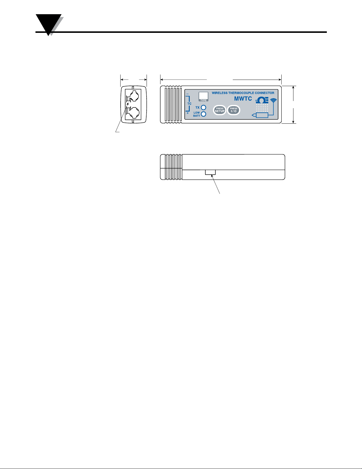
Section 4 – Transmitter/Connector Operation
Figure 4-1 shows the general dimensions.
15.2
(0.6)
FEMALE UNI-CONNECTOR ACCEPTS
STANDARD MALE OSTW OR MINIATURE
MALE SMPW MATING CONNECTIONS
DIMENSIONS mm (in)
82.5 (3.25)
Figure 4-1. MWTC Overall Dimensions
25.4 (1.0)
MWTC-D USB PORT
4-1
Page 31
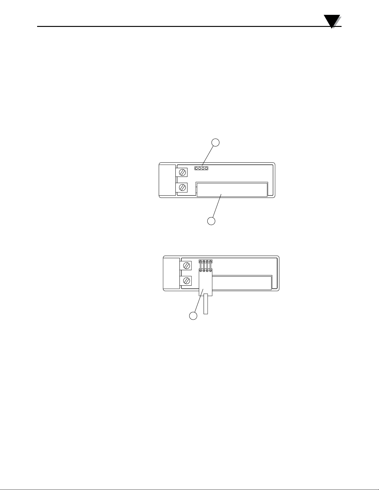
4.1 Setup and Configuration
4.1.1 Connecting Your Device
Connect the USB programming cable to your connector/transmitter unit and
alsotoanavailableUSBportonyourcomputer.Seeguresbelow.Thiscable
was provided in the box with your receiver unit.
For the MWTC-D, the USB cable is included with the transmitter. Simply connect
the cable to the USB connector on the side of the transmitter (you do not need to
open the unit) and into an available USB port on your PC, see Fig. 4-1.
Connecting Your Programming Cable
Connector Operation
1
+-
4
2
Figure 4-2A. Transmitter Programming Connection
3
Figure 4-2B. Transmitter Programming Connector with Cable Installed
(1) Programming Connector (2) Battery (3) Programming Cable
4-2
Page 32
4
Connector Operation
4.1.2 Congure Your Connector/Transmitter
Now that you have connected your USB cable to your PC and connector
transmitteryouwillcompletethefollowingstepstocongureyourconnector/
transmitter before placing the unit into operation. You will be using the
congurationsoftwareutilitythatyouinstalledontoyourPCinSection3.2.If
youhavenotinstalledthecongurationsoftwareutilityyoushoulddosonow.
During this procedure you will be setting the following parameters in your
connector transmitter.
Address Number
This sets a unique address number into your connector/transmitter. Later, when
you set up your measurement software you will again set channel numbers to
receive readings from the corresponding unit(s). Each connector must be set for
adierentaddressnumberforyoursystemtooperatecorrectly.
NOTE:
If you will be using more than one receiver unit in your area it is important to set
the connector/transmitter address numbers to be a corresponding number in your
TC-Central software. See Examples below.
For the first receiver:
Set the addresses on your connector/transmitters to 101, 102, 103, 104, etc. Then set
the channels in your TC-Central user software to match.
For the second receiver:
Set the addresses on your connector/transmitters to 201, 202, 203, 204, etc. Then set
the channels in your TC-Central user software to match.
This numbering scheme can be expanded to match the number of receivers you are
using. In addition RF Channel Frequency should be different, between 1st and 2nd
receivers.
4-3
Sample Rate (Recording Interval)
This will program your device to transmit 1 data reading to your receiver at a
speciedtimeinterval.Availablesettingsare2,3,4,5,10,15,30,45,60,75,90
105, or 120 seconds. The same sampling rate is used for recording interval on
MWTC-D.
RF Channel
You can set RF Channel Frequency between Channels A, B, C.
Channel Logging Option
For MWTC-D you can set additional parameters for data logging option.
NOTE:
The sample rate you set will have the most direct effect on the life of the battery in
your connector/transmitter. It is recommended that you set the longest sample time
that your application can live with to extend time between battery replacement. See
Section 6 for more information on battery life.
STEP 1. Enter the “SETUP” mode.
To place your connector/transmitter into the “SETUP” mode for programming
follow this procedure.
Page 33
Connector Operation
4
–
TC
TX
LOW
+
BATT
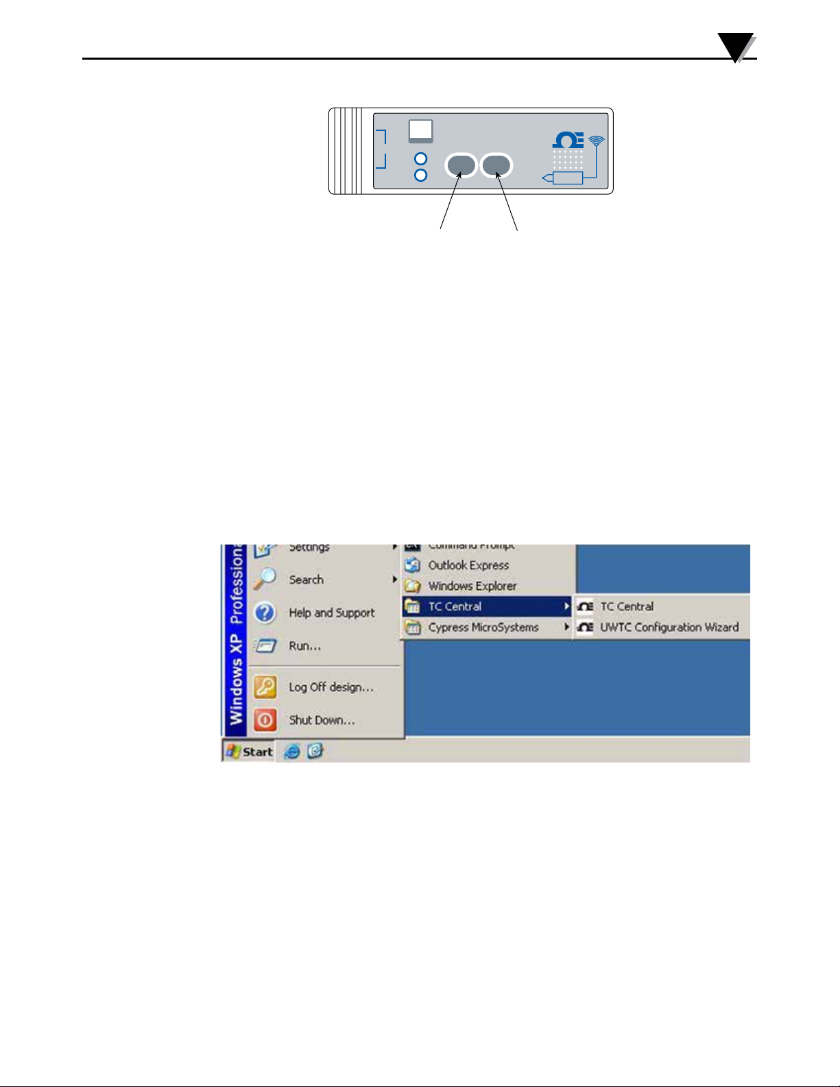
SETUP BUTTON ON/OFF BUTTON
WIRELESS THERMOCOUPLE CONNECTOR
TYPE
PRESS
SETUP
MWTC
PRESS
I / O
®
Figure 4-3. Setup Mode
Press and hold the “ON/OFF” button. While the “ON/OFF” button is being
held, press the “SETUP” button one time and then release the “ON/OFF”
button. The green (TX) indicator on the front of your device should be blinking
at a steady rate. This indicates your connector/transmitter is ready to run the
congurationutilitysoftware.
STEP 2. Launch Setup Utility Program.
To launch the MWTC Connector/Transmitter setup utility program on your PC
begin by accessing the “Programs” list under your “Start Menu”.
Scrollthroughthelistoftondthe“TC-Central”folder,thenselecttheMWTC
CongurationProgram.
Figure 4-4. Launch Setup Utility Program
4-4
Page 34
4
Connector Operation
STEP 3. Programing your settings into a connector/transmitter.
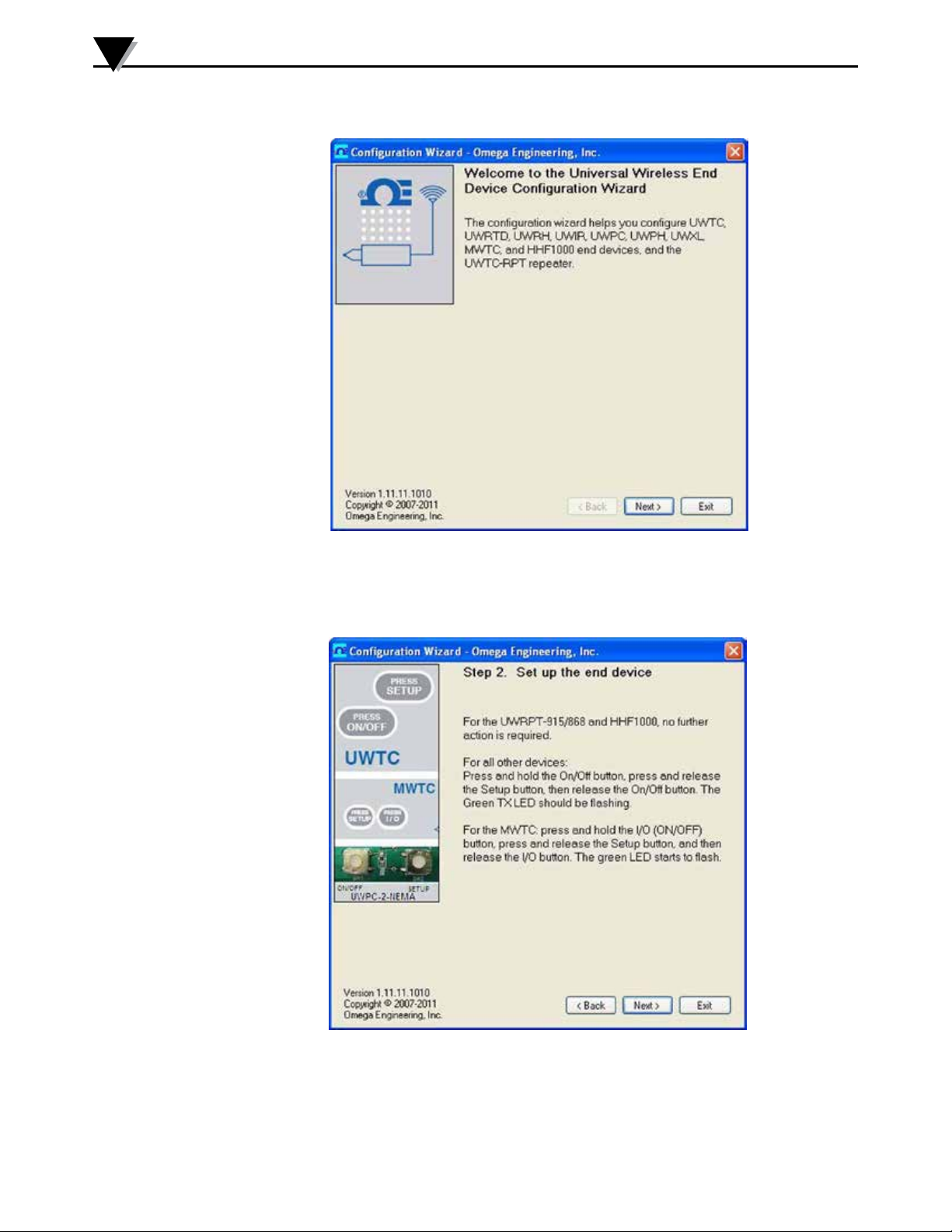
Figure 4-5.
Welcome To
Universal
Wireless
Screen
Afterstartingthesetuputilityprogramthiswillbetherstscreenyouwillsee.
Click the “Next >” button to proceed and continue setting up your connector/
transmitter. Each screen will provide instruction details on how to proceed.
Figure 4-6.
Setup The
Transmitter
Screen
4-5
If you have not already placed your connector/transmitter into the “Setup”
mode you should do this now before continuing. After your unit has been placed
into the “Setup” mode click the “Next >” button to proceed and continue setting
up your connector/transmitter.
Page 35
Connector Operation
Figure 4-7.
Connect The
Transmitter
Screen
4
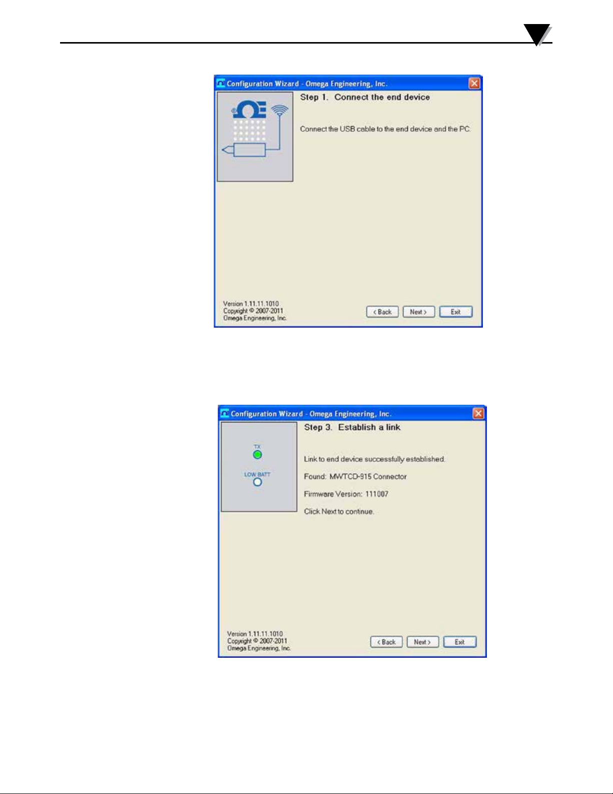
If you have not already connected your connector/transmitter to a USB port
on your PC you must do this now before continuing. After your unit has been
connected click the “Next >” button to proceed and continue setting up your
connector/transmitter.
Figure 4-8.
Establish A
Link Screen
After successful communication between your connector/transmitter has been
established you can click the “Next >” button to proceed and continue setting up
yourconnector/transmitter.Ifyoudidnotreceivethisconrmationofproper
communication you should click the “Back” button to try connecting again. If
you still do not obtain a good connection visit the “Troubleshooting” Section of
this users guide for addition.
4-6
Page 36
4
Connector Operation
Figure 4-9.
Choose
Options
Screen
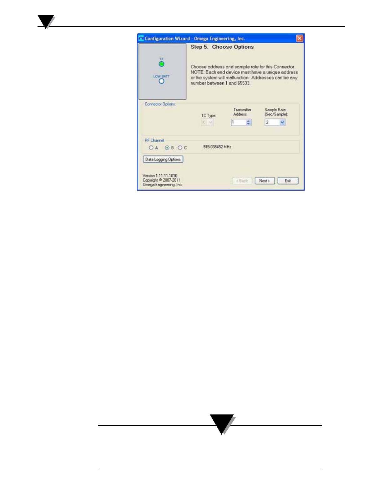
From this screen you will select the main operating settings for your connector/
transmitter. Start by selecting the address setting for this unit. (Note: Each
connector/transmittermusthaveadierentaddressnumberthanotherunits
in your system for proper operation). Then select the sample rate that your unit
will transmit data to the receiver.
RF Channel Selection
Hereyoucanselectfrom3channelschoices,thisgivesyoutheexibilityto
change the transmitting frequency should you have interference from other
devices close to your system, or using multiple wireless receivers (MWTC-REC1
or MWTC-REC5 or MWTC-REC6).
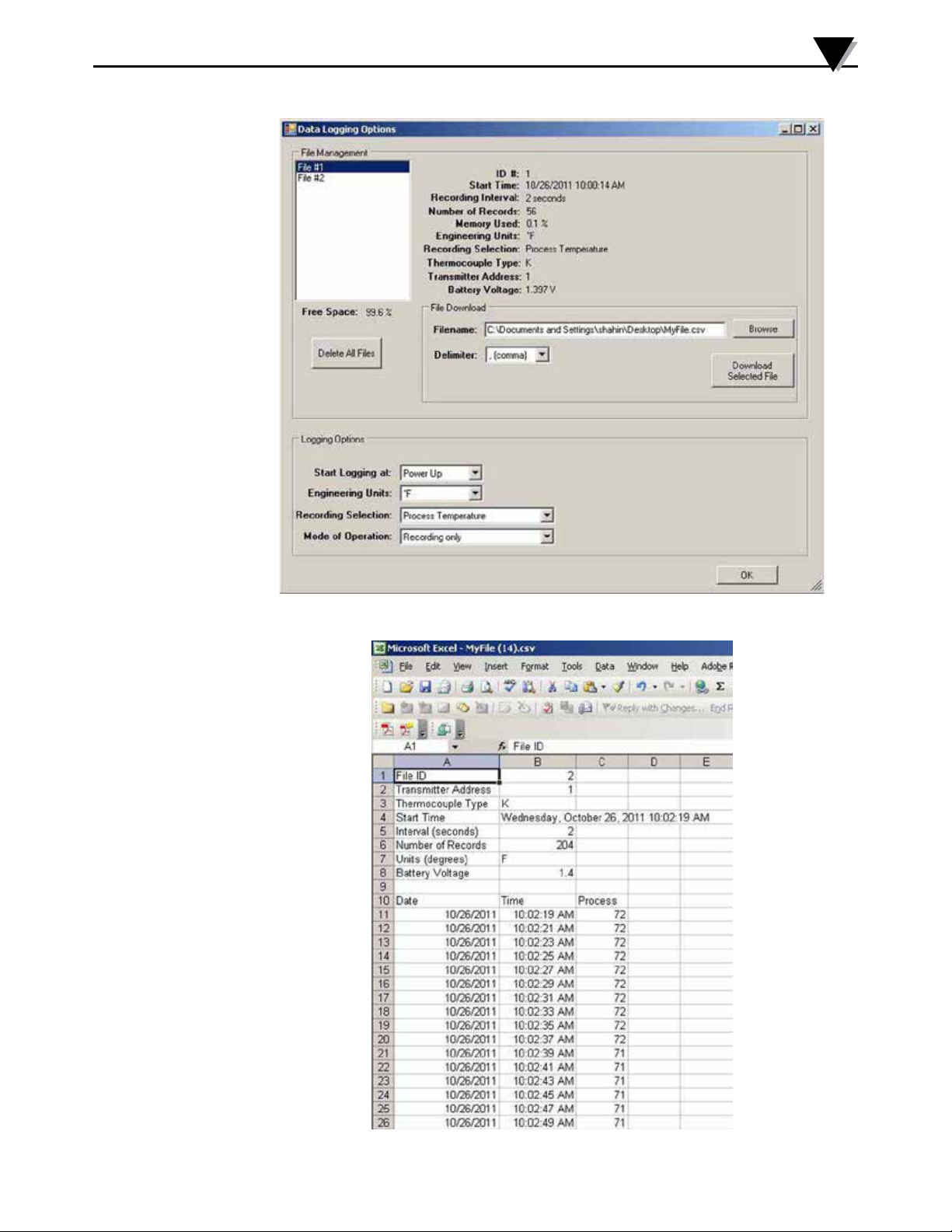
If you have MWTC-D, click on the Data Logging Options button to set additional
parameters as follows:
Start Logging: You can start the recording process either at Power up (When the
unit is turned on), or at a preset time & date. When the unit is set for preset time
& date, it will automatically turns itself on and starts to log and or transmit at
thespeciedtime&date.
Engineering Unit: You can select your Engineering unit from Deg F,C,K, and R.
Recording Selection: You can select from recording Process temperature or
Process & ambient temperatures.
Mode of Operation: You can select from Wireless only, Record only, or Wireless
& Recording combined.
Youcanalsodownloadselecteddatales(Upto8les)fromtheconnector.
Atypicaldataleisshowningure4-11.Youcanerasedatalesfromthe
connector.
NOTE:
4-7
MWTC-D can store up to 8 separate data files. When reached the end of the memory
or 8 data files, it will stop recording and the red and green LEDs will blink alternately.
In order to start the recording process again, you need to download the data files to
PC and then erase from the connector.
Page 37
Connector Operation
4
Figure 4-10. Data Logging Options Menu
Figure 4-11. Typical Data File
4-8
Page 38
4
Connector Operation
Figure 4-12. Send Settings To Transmitter Screen
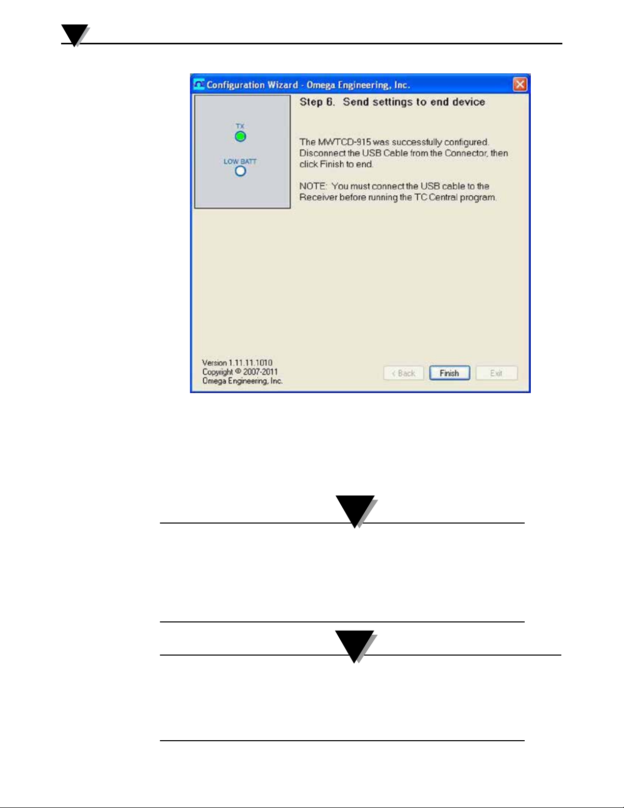
Congratulations! You have successfully programmed your connector transmitter.
After your unit has been programmed click the “Finish” button to close the utility
program or click the “Start” button to begin setting up a second unit. You can now
disconnect your connector transmitter from the programming cable. Press the
“Setup” button on the connector/transmitter one time to exit the “Setup” mode
NOTE:
Here are the default settings for the MWTC-D Wireless Transmitter/Logger
Recording / sampling interval = 5 seconds
Start Logging at = Power Up
Engineering unit = Deg F
Recording Selection = Process and Ambient Temperature
Mode of operation = Wireless Only
NOTE:
When operating the MWTC-D for the first time, or every time the battery is replaced,
you need to configure the unit using the End Device Configuration Wizard program.
It allows you to set up logging parameters such as current time & date, recording
interval, Start Logging Mode, Recording selection, and mode of operation.
The current Time & Date is lost when the battery is removed.
4-9
Page 39

Connector Operation
4
Here is a Figure 4-12A showing the operation status vs. the LED indications for
MWTC-D:
Operation Status LED Indications
Open Sensor Input Red LED blinks immediately after every Green
LED blink
Wireless Transmission, Green LED blinks every transmission interval
when pressing I/O key
Logging Mode, Red LED blinks once, then the Green LED
when pressing I/O key blinks every recording interval
Wireless & Logging Mode combined, Red LED blinks twice, then the Green LED
when pressing I/O key blinks every transmission/recording
interval
Turning the unit off – Press I/O key Red LED blinks three times
Low Battery – Red & Green LED blinks together
every transmission/recording interval
Low Battery – Red & Green LED blinks together
Open Sensor Input every transmission/recording interval
followed by one more Red LED blink
Memory Full – Logging Mode Red & Green LED blinks alternately 5 times
followed by 3 Red LED blinks indicating the unit
is off
Memory Full – Wireless and Red & Green LED blinks alternately 5 times
Logging Mode combined times followed by Green LED blinking every
transmission interval. Logging stops.
Set Up/ Configuration Mode – Press Green LED blinks continuously every 0.5
and Hold I/O key, then press Set up seconds
key, then release both keys
Figure 4-12A. MWTC-D Operation Status vs. LED Indicator
4.2 Mounting, Installation and Antenna Connection
4.2.1 Mounting Bracket Installation
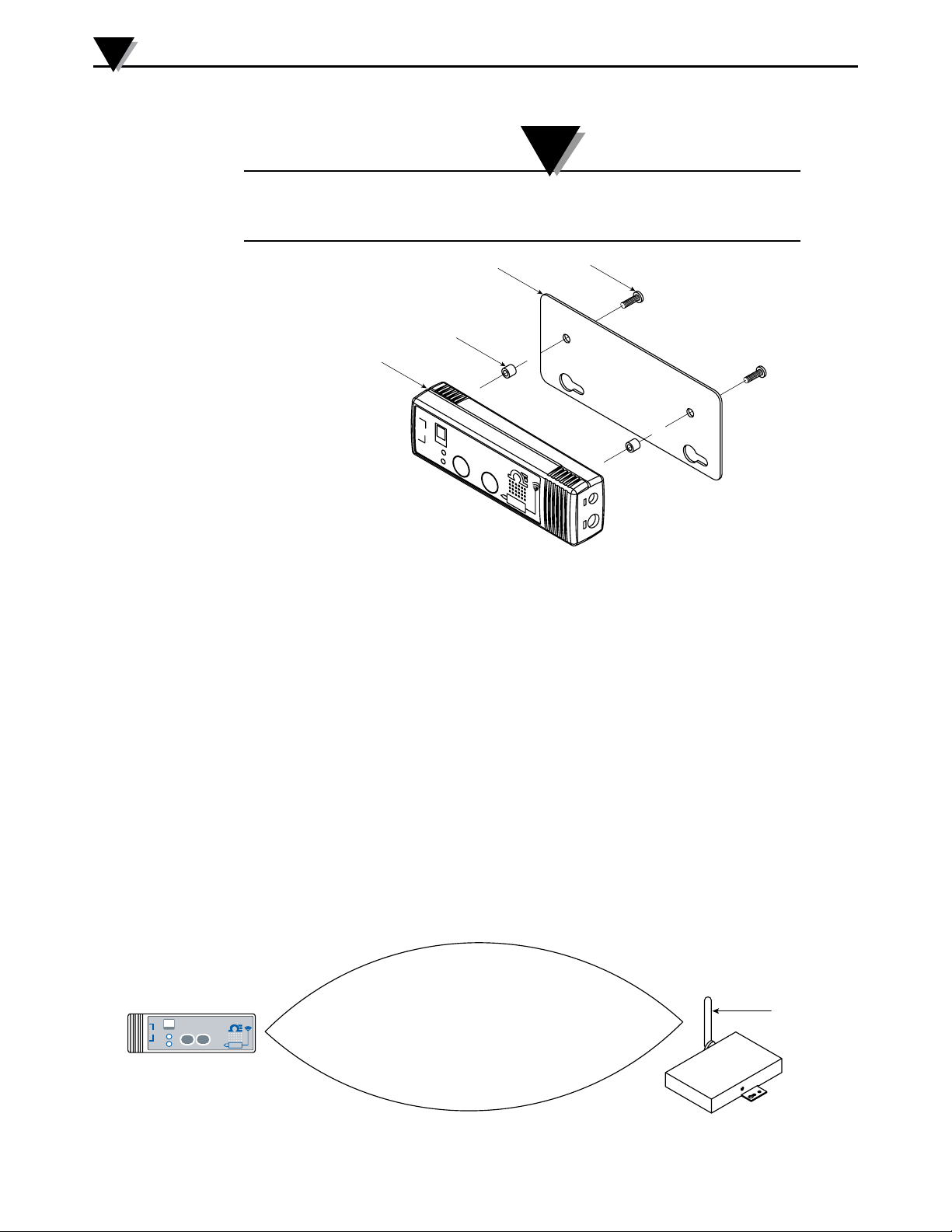
A mounting bracket kit has been supplied with your connector/transmitter. The
diagram below shows dimensions and how to install your mounting bracket.
4-10
Page 40
4
RECEIVER
Connector Operation
NOTE:
TIP: Use the plate as a template to mark the location of the mounting holes you need to
drill before installing the mounting kit onto the connector transmitter.
MOUNTING
BRACKET
MOUNTING
SCREW
SPACER
MWTC UNIT
-
WIRELESS THERMOCOUPLE CONNECTOR
TC
TYPE
+
TX
MWTC
LOW
BATT
P
RESS
SETUP
PRES
I/0
S
Figure 4-13. Mounting Bracket Installation
4.2.2 Mounting
When mounting your connector/transmitter, care should be taken to make sure
it is as far away from any metal objects. If nearby metal gets too close to your
connector/transmitter, it has the potential to interfere with the way the unit
radiates and may cause signal lose or possibly even the inability to communicate
at all with your receiver.
4-11
WIRELESS THERMOCOUPLE CONNECTOR
–
TYPE
TC
TX
LOW
+
BATT
4.2.3 Installation
When installing your connector/transmitter it is important to position your
device in such a way as to optimize the antenna location within what’s known as
the “Fresnel Zone”.
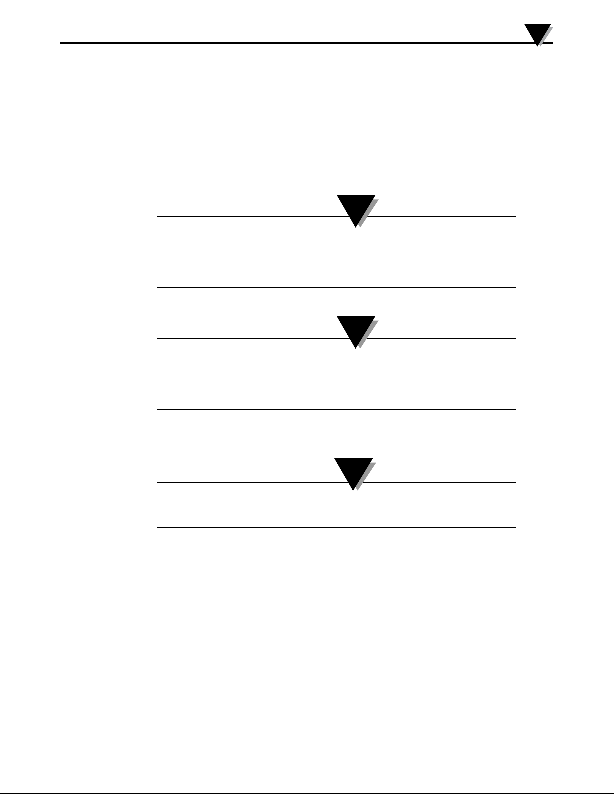
The Fresnel Zone can be thought of as a football-shaped invisible tunnel between
two locations that provides a path for RF signals between your connector/
transmitter and your receiver.
MWTC
®
PRESS
PRESS
SETUP
I / O
FRESNEL ZONE
Figure 4-14. Fresnel Zone
ANTENNA
Page 41
Connector Operation
In order to achieve maximum range, the football-shaped path in which radio
waves travel must be free of all obstructions. Obstacles in the path (especially
metal) will decrease the communication range between your connector/
transmitterandreceiver.Also,Iftheantennasaremountedjustbarelyothe
ground, over half of the Fresnel zone ends up being obstructed by the earth
resultinginsignicantreductioninrange.Toavoidthisproblem,theantennas
shouldbemountedhighenoughoofthegroundsothattheearthdoesnot
interfere with the central diameter of the Fresnel zone.
NOTE:
It is important to understand that the environment may change over time due to new
equipment or machinery being installed, building construction, etc. If new obstacles exist
between your connector/transmitter and receiver, the devices can be raised on one end
or on both ends to hopefully clear the Fresnel Zone of obstructions.
4
NOTE:
No co-location with other radio transmitters is allowed. By definition, co-location is
when another radio device or it’s antenna is located within 20 cm of your connector/
transmitter and can transmit simultaneously with your MWTC unit.
Never install MWTC connector/transmitters within 20 cm or less from each other.
4.2.4 Antenna
NOTE:
Use of any other antenna then what’s supplied with your device will void all FCC and
CE regulatory compliance.
Additional Information on installation and system operation can be found in
Section 6.
4-12
Page 42
4
Connector Operation
4.3 - Thermocouple Connections
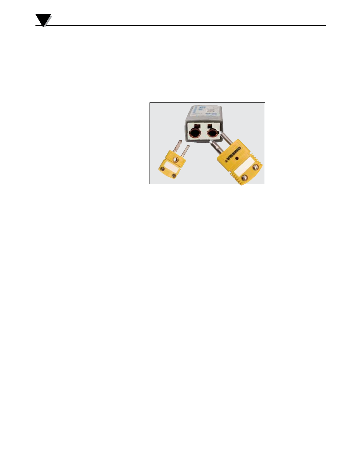
Your connector/transmitter has been design with a patented universal input
that will interface with most industry thermocouple connectors. Omega’s
Miniature (SMP) Series and Standard (OST) Series of connectors will plug
directly into the side of your unit. Omega’s line of thermocouple probes with
connectors attached will also plug directly into your unit.
Universal input
accepts standard and
miniature connectors.
Figure 4-15. Thermocouple Connection
4.3.1 Thermocouple Operating Environment and Placement
4.3.2 Ambient Temperature Concerns
Your Connector/Transmitter is rated for use in ambient temperatures between
-10 to 70°C (14 to 158°F). Exposure to temperatures below or above these stated
temperatures can cause your device to malfunction and produce incorrect
operation. When installing your thermocouple probe care should be taken to
make sure your connector/transmitter will not be operated in an environment
outsidethespecicationsoutlinedinSection9.
4.3.3 Recommended Placement
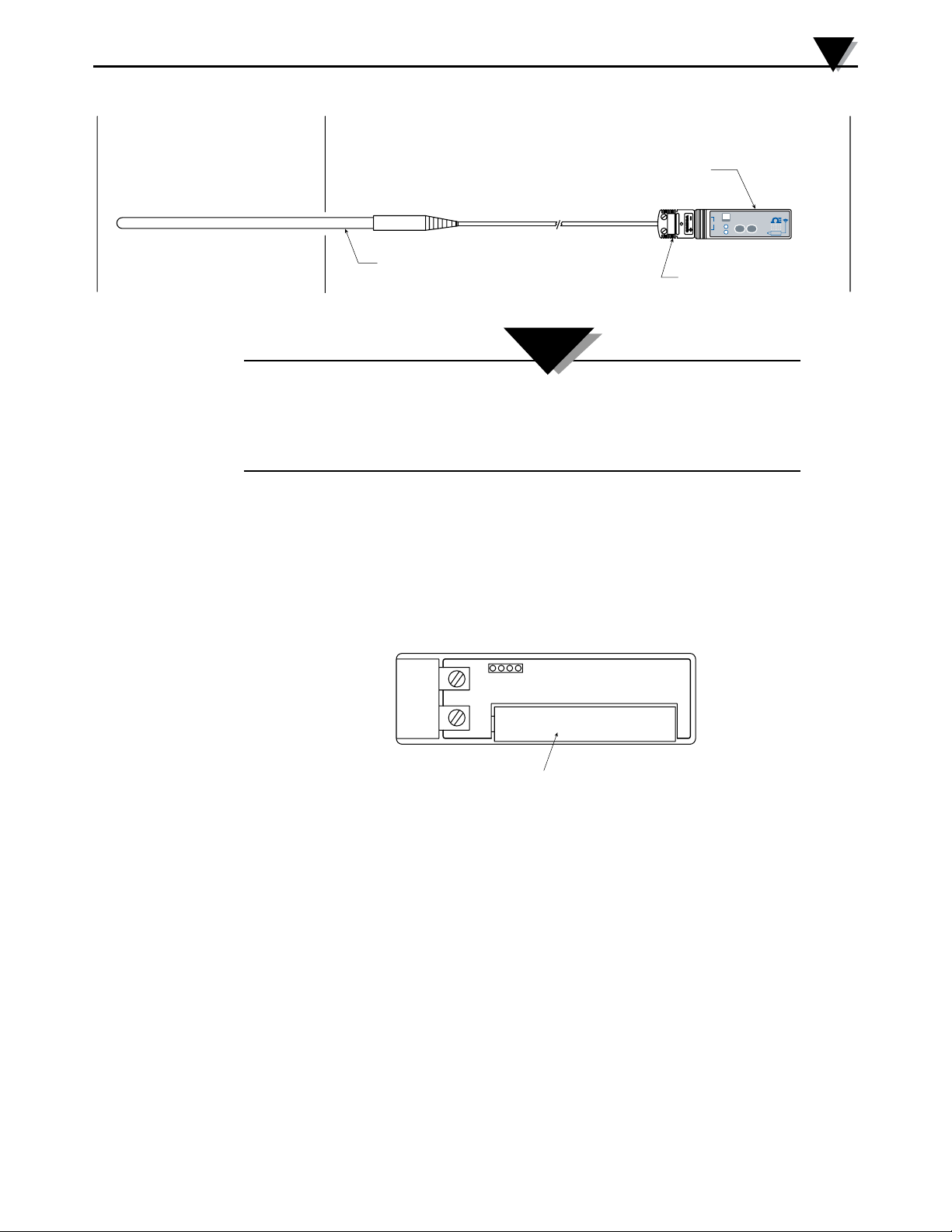
For applications were the ambient temperature around the thermocouple probe
has the possibility of exceeding the operating conditions outlined in Section 9
of this manual, the connector/transmitter should be mounted away from the
thermocouple probe in an area within the normal operating conditions of -10 to
70°C (14 to 158°F). See Below.2
4-13
Page 43
THERMOCOUPLE
SAFE
MEASUREMENT AREA
AMBIENT AREA
CONNECTOR/TRANSMITTER
Connector Operation
WIRELESS THERMOCOUPLE CONNECTOR
–
MWTC
TYPE
TC
TX
LOW
+
BATT
®
PRESS
PRESS
SETUP
I / O
4
THERMOCOUPLE PROBE
Figure 4-16. Recommended Thermocouple Placement
Installing your connector/transmitter in an application were the device will be exposed
to ambient temperatures above or below the operating limits specified in this manual
will damage your unit and cause the unit to malfunction and produce incorrect
operation.
4.4 Battery Installation or Replacement
4.4.1 Model MWTC-(*)-915
ToinstallorreplacethebatteryinyourConnector/Transmitteryoumustrst
remove the two screws located on the back side of your device. This will allow
you to access the battery compartment.
MATING CONNECTOR
CAUTION:
+ -
BATTERY (NOTE POLARITY)
Figure 4-17. Battery Compartment
4-14
Page 44
4
Connector Operation
WARNING:
Lithium batteries may get hot, explode or ignite and cause serious injury if exposed
to abusive conditions. Be sure to follow the safety warnings listed below: Your MWTC
Transmitter operates with one 1.5V AAA Lithium Battery. Omega Replacement Part Number
MWTC-A-BATT. Never operate your MWTC transmitter with a different battery than what is
specified in this manual or on the MWTC data sheet. Do not discharge the battery using any
device except your MWTC Transmitter unit. When the battery is used in devices other than
the specified device, it may damage the battery or reduce its life expectancy. If the device
causes an abnormal current to flow, it may cause the battery to become hot, explode or
ignite and cause serious injury. Refer to the Omega technical data sheet or this manual for
the temperature ranges over which the battery can be operated. Use of the battery outside
this temperature range may damage the MWTC Transmitter or reduce the performance and
life of the battery.
• Do not place the battery in fire or heat the battery.
• Do not store batteries with other hazardous or combustible materials.
• Do not install the battery backwards so the polarity is reversed.
• Do not connect the positive terminal and negative terminal of the battery to each
other with any metal object (such as wire).
• Do not carry or store the battery together with metal objects.
• Do not pierce the battery with nails, strike the battery with a hammer, step on the
battery or otherwise subject it to strong impacts or shocks.
• Do not solder directly onto the battery.
• Do not expose battery to water or salt water, or allow the battery to get wet.
• Do not disassemble or modify the battery.
• When the battery is discharged, insulate the terminals with adhesive tape or
similar materials before disposal.
• Immediately discontinue use of the battery if, while using or storing the battery,
the battery emits an unusual smell, feels hot, changes color or shape, leaks or
appears abnormal in any other way. Contact Omega if any of these problems
are observed.
• Do not place the battery in microwave ovens or high-pressure containers.
• Always dispose of discharged batteries in accordance with all local, state and
national laws.
4-15
WARNING:
• Immediately discontinue use of the battery if, while using or storing the
battery, the battery emits an unusual smell, feels hot, changes color or shape,
leaks or appears abnormal in any other way. Contact Omega if any of these
problems are observed.
• Do not place the battery in microwave ovens, high pressure containers.
• Always dispose of discharged batteries in accordance with all local, state and
national laws.
Page 45
Section 5 - Receiver Operation
3
1
2
USB RECEIVER
®
TX
PWR
MWTC SERIES
WIRELESS RECEIVER
Software
5
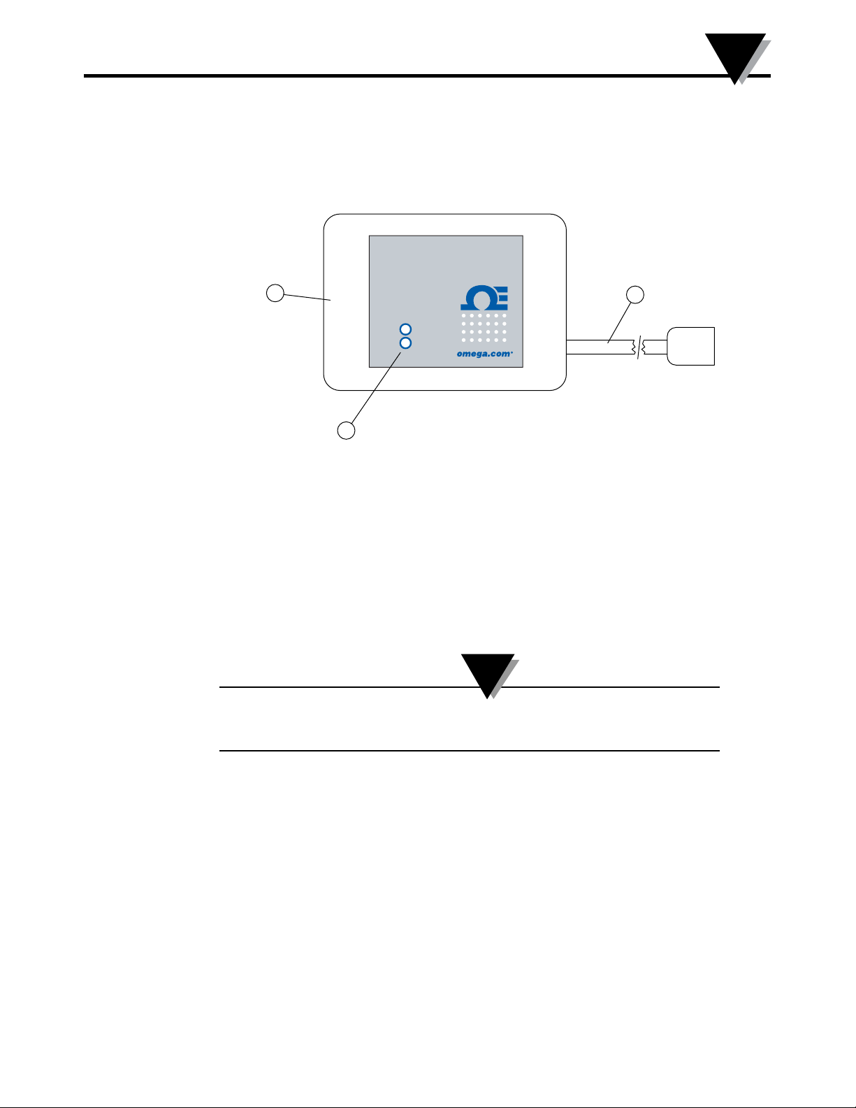
Model: MWTC-REC1
Figure 5-1. Receiver Operation - Model MWTC-REC1
5.1 Mounting, Installation
Antenna ② USB Port (mini-B) ③ Indicator Lights
①
5.1.1 Mounting
A mounting bracket was included with included with your receiver. The
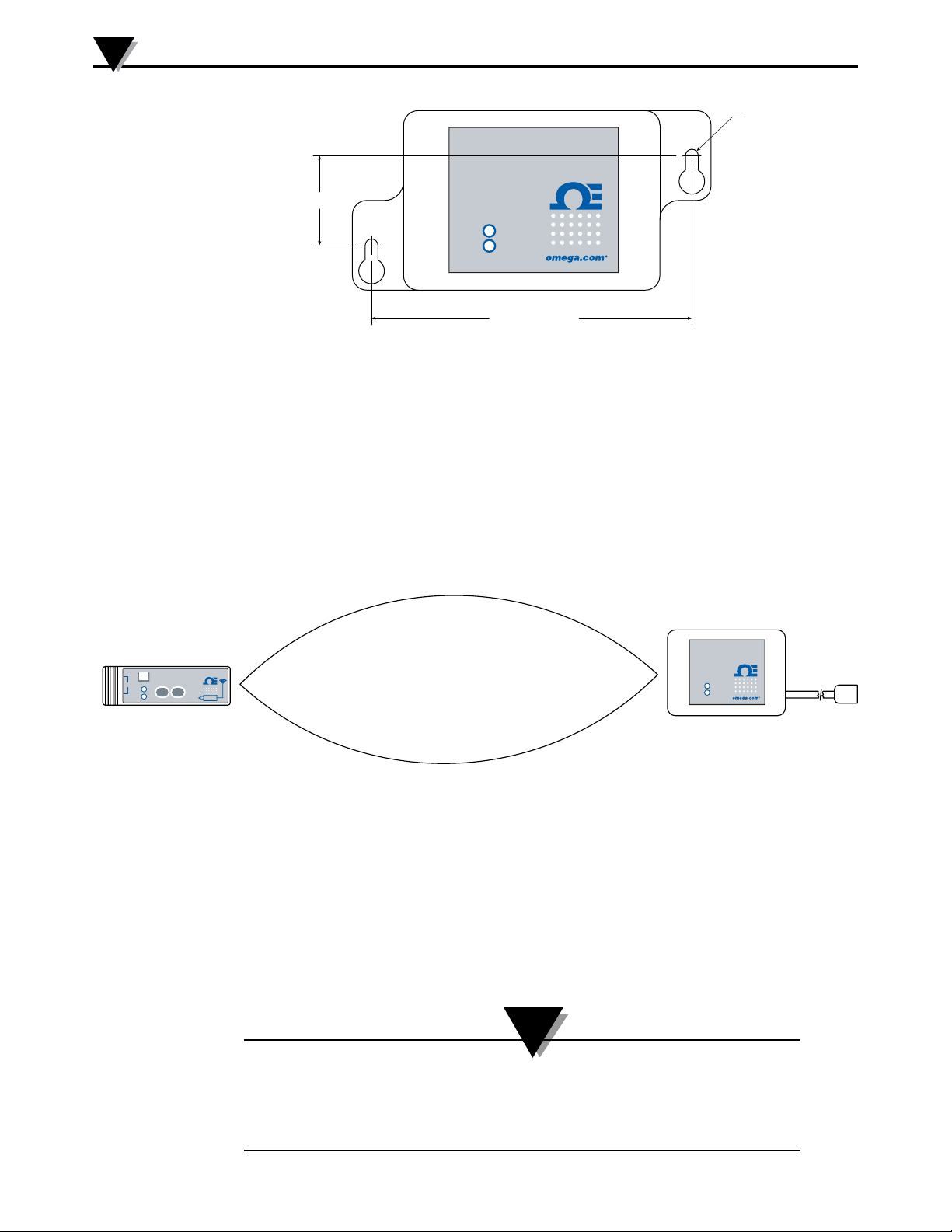
diagram below shows dimensions and mounting hole location. Rubber bumpers
have also been supplied with your receiver should you wish to use the device on
a desk or a work bench next to your PC.
NOTE:
TIP: Mounting your receiver on a wall away from your PC will provide better signal
strength and help to maximize system range.
When mounting your receiver, care should be taken to make sure it is as far
away from any metal objects. If nearby metal gets too close to your receivers
antenna, it has the potential to interfere with the way the unit receives data and
may cause signal lose or possibly even the inability to communicate at all with
your connector/transmitter.
5-1
Page 46
5
3.2 (0.125) DIA.
Receiver Operation
MWTC SERIES
WIRELESS RECEIVER
2 PLACES
WIRELESS THERMOCOUPLE CONNECTOR
–
TYPE
TC
TX
LOW
+
BATT
23 (0.87)
TX
PWR
®
79 (3.12)
DIMENSIONS mm (in)
Figure 5-2. Mounting
5.1.2 Installation
When installing your receiver it is important to position your device in such a
way as to optimize the antenna location within what’s known as the “Fresnel
Zone”.
The Fresnel Zone can be thought of as a football-shaped invisible tunnel between
two locations that provides a path for RF signals between your connector/
transmitter and your receiver
MWTC SERIES
WIRELESS RECEIVER
MWTC
®
PRESS
PRESS
SETUP
I / O
FRESNEL ZONE
®
TX
PWR
5-2
Figure 5-3. Installation
In order to achieve maximum range, the football-shaped path in which radio
waves travel must be free of all obstructions. Obstacles in the path (especially
metal) will decrease the communication range between your connector/
transmitterandreceiver.Also,Iftheantennasaremountedjustbarelyothe
ground, over half of the Fresnel zone ends up being obstructed by the earth
resultinginsignicantreductioninrange.Toavoidthisproblem,theantennas
shouldbemountedhighenoughoofthegroundsothattheearthdoesnot
interfere with the central diameter of the Fresnel zone.
NOTE:
It is important to understand that the environment may change over time due to new
equipment or machinery being installed, building construction, etc. If new obstacles exist
between your connector/transmitter and receiver, the devices can be raised on one end
or on both ends to hopefully clear the Fresnel Zone of obstructions.
Page 47
Section 6 - System Operation
6.1 Introduction
Compared to wired thermocouple systems, wireless thermocouple systems
provide much simpler installation. Based on the physical principle of the
propagation of radio waves, certain basic conditions should be observed. The
following simple recommendations are provided to insure proper installation
and correct operation of your MWTC Series system.
6.2 RF Communication Basics
The Model MWTC wireless Thermocouple Connector/Transmitter sends
wireless transmissions to the MWTC-REC1, MWTC-REC5, or MWTC-REC6
receiver. The receiver checks the incoming data for accuracy and processes
this data for use by the measurement software on your PC. Radio signals are
electromagnetic waves, hence the signal becomes weaker the further it travels.
While radio waves can penetrate some solid materials like a wall, they are
dampened more than when a direct line-of-sight between the transmitting and
receiving antenna exist.
System Operation
6
6.3 Basic System Overview
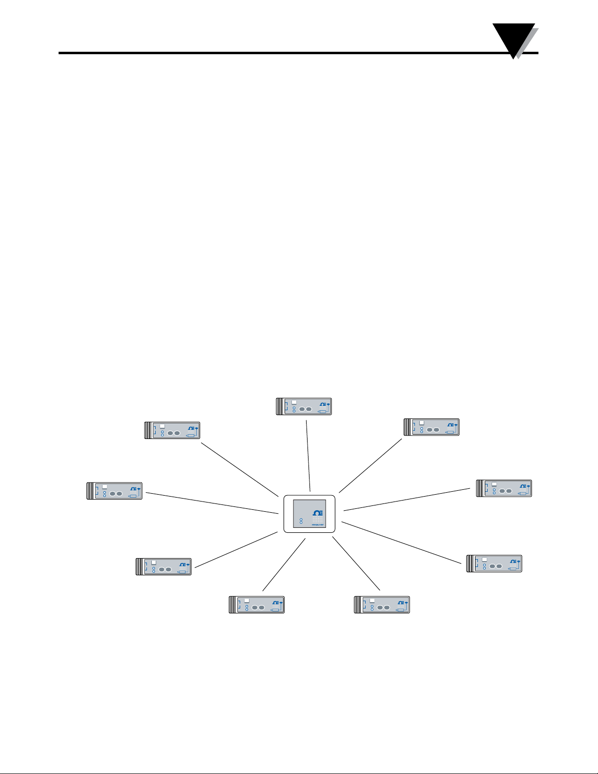
The MWTC wireless thermocouple system is comprised of only two main
components; a Thermocouple Connector with a built-in battery powered radio
transmitter, and a USB powered radio receiver.
WIRELESS THERMOCOUPLE CONNECTOR
–
MWTC
TYPE
®
PRESS
PRESS
SETUP
I / O
MWTC
®
PRESS
PRESS
SETUP
I / O
–
TYPE
TC
TX
LOW
+
BATT
WIRELESS THERMOCOUPLE CONNECTOR
MWTC
®
PRESS
PRESS
SETUP
I / O
TC
+
–
TYPE
TC
TX
LOW
+
BATT
TX
LOW
BATT
WIRELESS THERMOCOUPLE CONNECTOR
–
TYPE
TC
TX
LOW
+
BATT
WIRELESS THERMOCOUPLE CONNECTOR
MWTC
®
PRESS
PRESS
SETUP
I / O
–
TYPE
TC
TX
LOW
+
BATT
WIRELESS THERMOCOUPLE CONNECTOR
MWTC
®
PRESS
PRESS
SETUP
I / O
MWTC SERIES
WIRELESS RECEIVER
®
TX
PWR
–
TYPE
TC
TX
LOW
+
BATT
WIRELESS THERMOCOUPLE CONNECTOR
MWTC
®
PRESS
PRESS
SETUP
I / O
–
TYPE
TC
TX
LOW
+
BATT
WIRELESS THERMOCOUPLE CONNECTOR
MWTC
®
PRESS
PRESS
SETUP
I / O
–
TC
+
–
TYPE
TC
TX
LOW
+
BATT
WIRELESS THERMOCOUPLE CONNECTOR
MWTC
TYPE
TX
PRESS
PRESS
SETUP
I / O
LOW
BATT
WIRELESS THERMOCOUPLE CONNECTOR
MWTC
®
PRESS
PRESS
SETUP
I / O
®
Figure 6-1. Basic System Overview
Up to 48 connector/transmitters can be used with MWTC-REC1, MWTC-REC5,
or MWTC-REC6 receivers.
6-1
Page 48
6
System Operation
6.4 Connector/Transmitter Operation
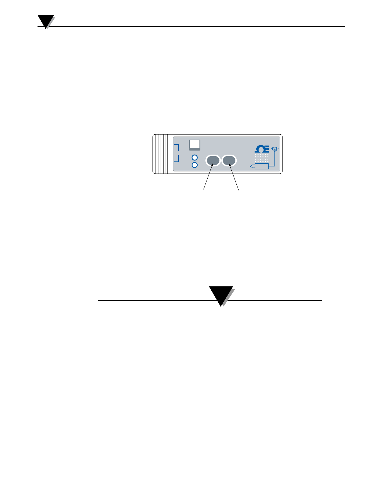
6.4.1 Button Operation
(1.) “PRESS ON/OFF”
The “PRESS ON/OFF” button on the front of your connector/transmitter is used
to turn your unit “ON” or “OFF”
(2.) “PRESS SETUP”
The “PRESS SETUP” button on the front of your connector/transmitter is only
usedduringthesetupandcongurationofyourunit.SeeSection4.1.2formore
information.
–
TC
TX
LOW
+
BATT
SETUP BUTTON ON/OFF BUTTON
WIRELESS THERMOCOUPLE CONNECTOR
TYPE
PRESS
SETUP
MWTC
PRESS
I / O
®
Figure 6-2. Button Operation
6.4.2 Ambient Temperature Readings
The ambient temperature reading displayed on your screen when running the
TC-Central program, is the actual ambient temperature that your connector/
transmitter is being exposed to. This reading is only provided as reference and to
aid you in proper installation of your unit. The ambient temperature reading will
blink and change to RED digits to alert you that your have exceed the maximum
recommended safe operating conditions for your connector/transmitter. You
should not rely on this feature as sole protection. Additional protection should
be taken by you “the user” to protect your unit from extreme conditions.
NOTE:
Operating your connector/transmitter outside the specified ambient conditions listed
in Section 9 of this manual may cause your unit to malfunction and stop working
correctly.
6-2
6.4.3 Indicator Lights
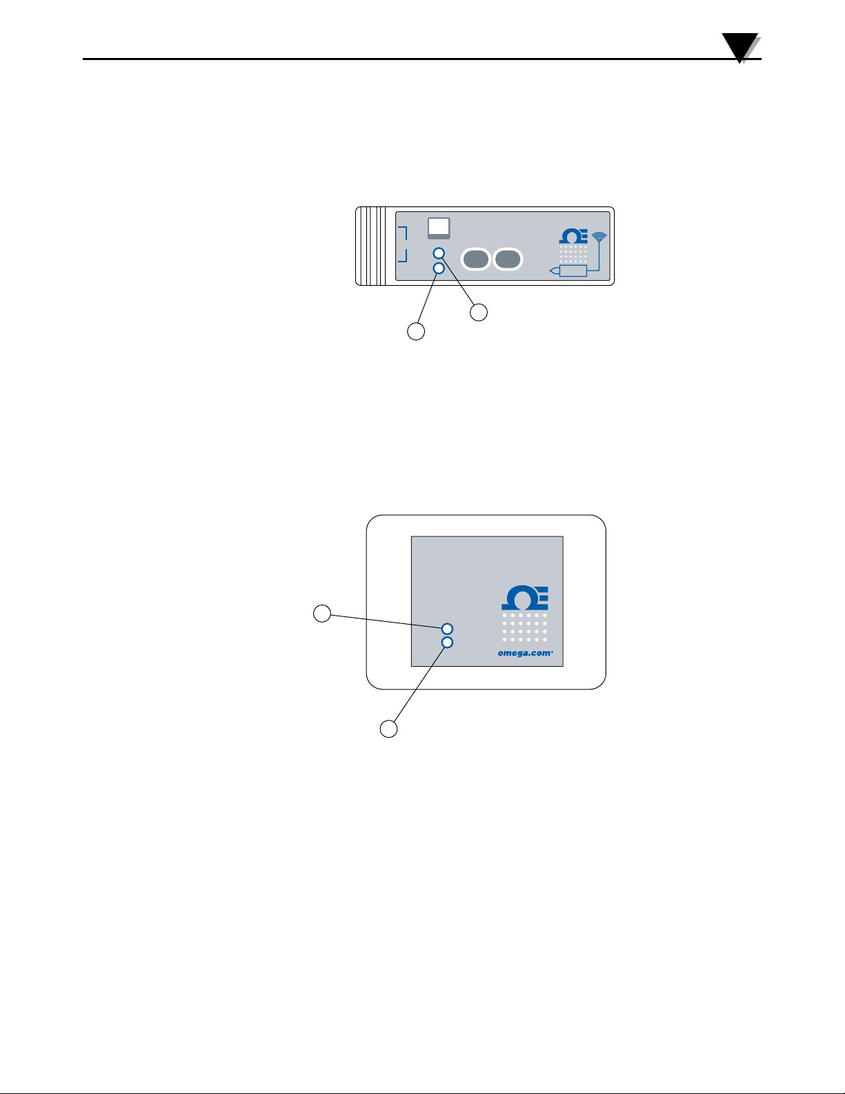
Transmit (TX) Green Indicator Light
①
The green indicator light marked “TX” on the front of the connector/transmitter
will blink every time the unit sends data to the receiving unit. Example; If you
selected a 5 sec sample rate the green TX led will blink one time every 5 seconds.
Low Battery (Low Bat) Red Indicator Light
②
The red indicator light marked “Low Bat” on the front of the connector/
transmitter will blink when the battery voltage reaches a level at or below the
power level required for normal operation. When this indicator turns on it’s time
to install a fresh battery in your unit. For procedures on how to change your
battery see Section 4.5. For information on battery life see Section 6.11.
(See diagram on next page)
Page 49
System Operation
6
If the red LED blinks twice or is out of sequence from the green LED, it is an
indication of an open thermocouple input (MWTC-D).
On the MWTC-D, when turning on the unit, if the red LED blinks once, it means
record only. If the red LED blinks twice, it means record & wireless together. If
the red LED does not blink, it means wireless only.
6.5 Receiver Operation
6.5.1 Indicator Lights
–
TC
LOW
+
BATT
2
WIRELESS THERMOCOUPLE CONNECTOR
PRESS
MWTC
PRESS
I / O
1
TYPE
TX
SETUP
®
Figure 6-3. Transmit and Low Battery Lights
USB RECEIVER
MWTC SERIES
WIRELESS RECEIVER
®
2
TX
PWR
1
Figure 6-4. Indicator Lights
Power (PWR) Green Indicator Light
①
Transmit/Receive (TX) Red Indicator Light
②
The red indicator light marked “TX” on the front of the receiver will blink each
time the receiver receives incoming data during USB programming and also
when data is received from one of your transmitters.
6-3
Page 50

6
System Operation
6.6 Environment/Operating Conditions
6.6.1 Environment
Omega’s MWTC series connector/transmitter and receiver unit has been
designedtobexedmountedandoperatedinacleananddryindoor
environment. Care should be taken to prevent the components of your wireless
system from being exposed to moisture, toxic chemicals and extreme cold or hot
temperaturethatareoutsidethespecicationslistedinthismanual.
6.6.2 Operating Conditions
The following is a list of basic good practice you should apply when operating
your wireless system.
• Never operate your wireless device outside the recommended
environmentallimitsspeciedinthismanual.
•Neveroperateyourwirelessdeviceinammableorexplosive
environments.
• Never use your wireless device in medical, nuclear or other dangerous
applications were failure can cause damage or harm.
• Never operate your transmitter/connector with any other battery or power
sourcethanwhat’sspeciedinthismanualoronthebatterycompartment
label.
•Noco-locationwithotherradiotransmittersisallowed.Bydenition,
co-location is when another radio device or it’s antenna is located within
20 cm of your connector/transmitter and can transmit simultaneously with
your MWTC unit.
• Never install a connector/transmitters within 20 cm or less from each other.
• Never use your connector/transmitter as a portable device. Your unit has
been designed to be operated in a permanent installation.
• Never install and/or operate your connector transmitter closer than 20 cm
to nearby persons.
• Never operate your connector transmitter with any other antenna than what
is supplied or listed here in this manual for approved use.
6-4
Page 51
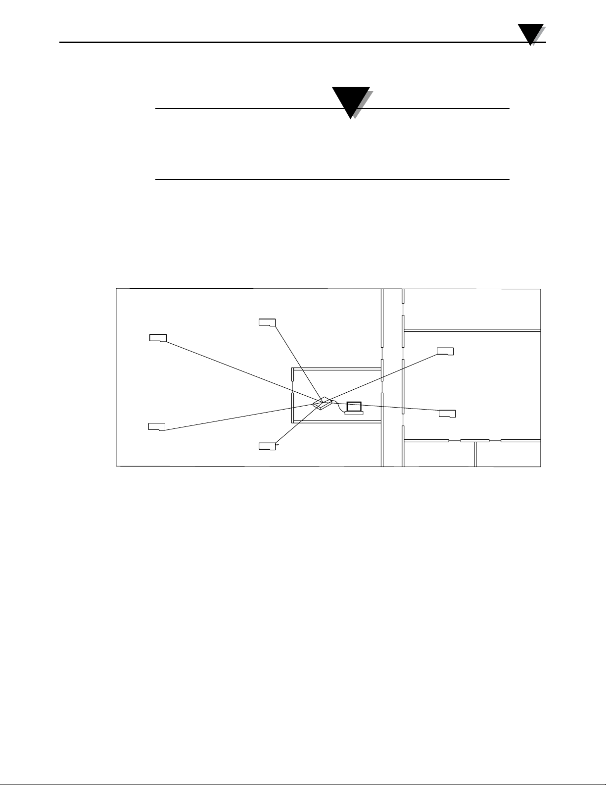
6.7 Determining and Maximizing Range
The available maximum range specified for the wireless Series system in this manual is
only achievable under optimum installation conditions. Mounting height, obstructions
in your “Fresnel Zone” and ambient conditions can cause a decrease in signal strength
resulting in a shorter range between your transmitter/connector and receiver unit.
The following recommendations will help to improve the range of your wireless
system.
Position your receiver in a central location
When multiple connector/transmitters are in operation, position your receiver
unit in a central space if possible in equal distance to each connector transmitter.
Figure 6-5. Determining Maximum Range
NOTE:
System Operation
6
STORAGE ROOM
TRANSMITTER
CHAN 1
MANUFACTURING
AREA
TRANSMITTER
CHAN 2
TRANSMITTER
CHAN 6
MANUFACTURING
AREA
TRANSMITTER
CHAN 5
TRANSMITTER
CHAN 3
TRANSMITTER
CHAN 4
CONTROL ROOM
RECEIVER
PC
OFFICE OFFICE
Test your system before permanent mounting
Before permanently mounting your connector/transmitters in your application
trymovingthedevicestodierentlocationsandmountinganglestodetermine
what installation achieves the best signal strength.
Move your system components higher o the oor and away from exterior walls
Avoidinstallingyoursystemcomponentstoclosetotheoorornearyour
buildings exterior walls. The closer your connector/transmitter and receiver unit
are the greater the interference and lose of signal strength will be.
Maintain a line of sight (LOS) between antennas
Maintaining a line of sight between your connector/transmitter and receiver
unit will produce greatly improved signal strength over a system were the
antenna’s in your system have obstacles blocking them.
Maintain a constant ambient temperature environment
Maintaining a constant ambient temperature environment is important to
achieving maximum signal strength. Exposing your system components to
extreme hold or cold temperatures, or sudden changes in ambient conditions
willhaveaneectontheperformanceofyoursystem.
6-5
Page 52

6
System Operation
6.7.1 Operation in Buildings
Your Connector/Transmitter sends wireless data transmissions to a receiver
connected to your PC. Radio signals are electromagnetic waves. A radio signal
becomesweakerthefurtherittravels.Rangeisdecreasedbydierenttypesof
materials found in the direction of the signals propagation. Radio waves can
penetrate most types of wall materials, but they are dampened more than they
would be by a direct line-of-sight installation.
6.7.2 Building Materials
Examplesofhowdierenttypesofwallmaterialmayreduceyoursignal:
Material Type Possible Signal Reduction
Wood, Plaster, Sheetrock, Uncoated 0 to 10%
Glass w/o Metal, Fiberglass
Brick, Pressboard 5 to 35%
Reinforced Concrete 10 to 90%
Metal Walls, Metal Doors, Elevators,
Metal Stair Cases, Metal Piping, 90 to 100%
Metal Mesh, Metal Screening
Figure 6-6. Operation In Buildings
Avoid dampening materials by repositions the connector/transmitting and/or
receiver.
6.7.3. Penetration Angle of Radio Waves Through Walls
The angle at which the transmitted radio signal hits a wall is very important
andalsohasabigeectonmaximizingrange.Signalsbetweenyourconnector/
transmitter should be transmitted as directly as possible.
6-6
Page 53

6.8 Antenna Basics
6.8.1 Antenna Basics
Bydenition,anantennaisadeviceusedtotransformanRIsignal,travelingon
a conductor, into an electromagnetic wave in free space. Antennas demonstrate
a property known as reciprocity, this means that an antenna will always
maintain the same characteristics regardless if it is used to transmit or receive.
Mostantennasareresonantdevices,whichmeanstheyoperateecientlyover
a relatively very narrow frequency band. An antenna must be tuned to the
same frequency band of the radio system to which it is connected, otherwise the
reception and the transmission will be impaired. The antennas in your wireless
thermocouple connector system have been tuned to operate in the 915 or 868
band.
6.9 Antenna Placement
Proper antenna installation is important and will allow you to achieve maximum
performance and range between your connector/transmitter and receiver unit.
NOTE:
System Operation
6
Your connector/transmitter should not be installed on the same side of the wall as the
receiver. If mounted close to each other on the same wall, the radio waves are likely
to be subject to interfering dispersions or reflections. The best positioning is to have the
connector/transmitter installed on the opposite or connecting wall to the receiver.
6.9.1 Horizontal Antenna Placement
Figure 6-7. Horizontal Antenna Placement
®
MWTC
I / O
PRESS
PRESS
SETUP
WIRELESS THERMOCOUPLE CONNECTOR
TYPE
TX
LOW
BATT
TC
–
+
WIRELESS RECEIVER
MWTC SERIES
TX
PWR
®
If your Connector/Transmitter is mounded in a horizontal position in your
application you should mount your receiving so that the same polarization is
achieved with the receiving antenna. As shown in the “Horizontal” example above.
6-7
Page 54
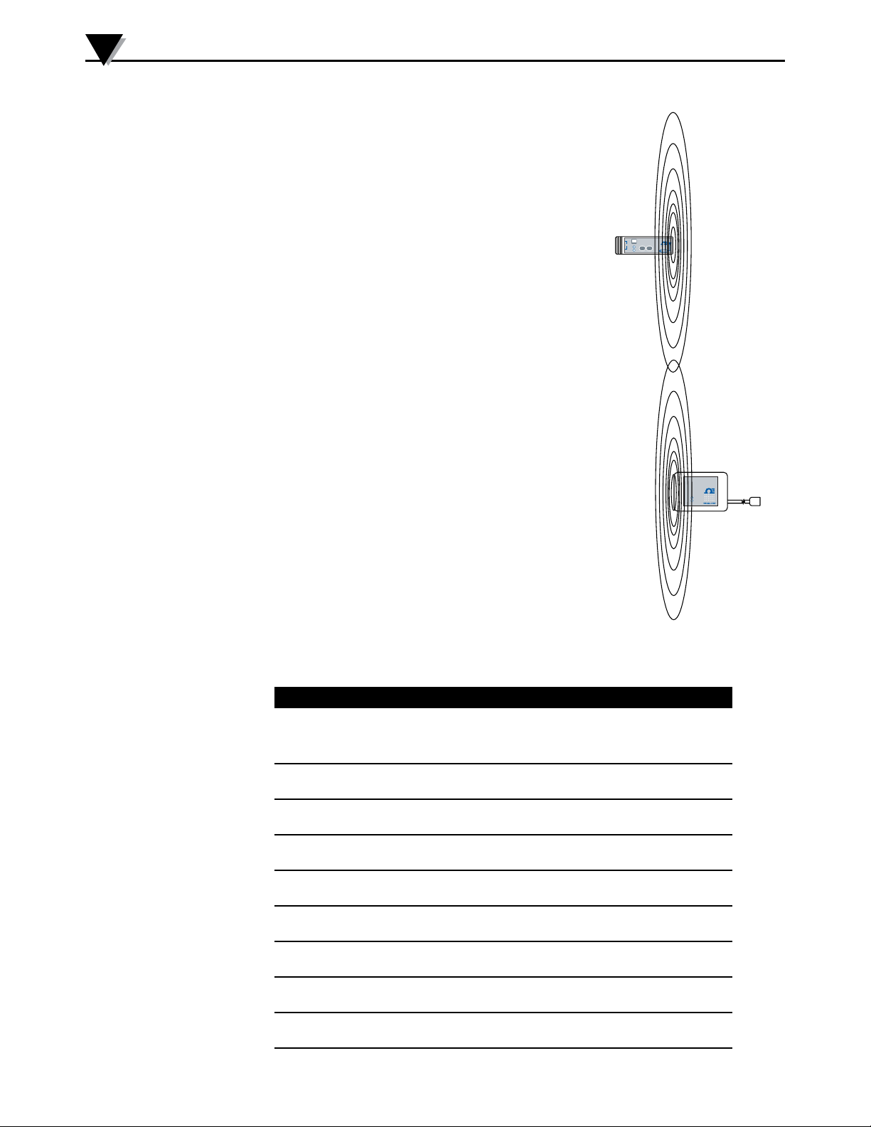
6
System Operation
6.9.2 Vertical Antenna Placement
If your Connector/Transmitter is mounded
in a vertical position in your application you
should mount your receiving so that the same
polarization is achieved with the receiving
antenna. As shown in the “Vertical” example
Fig 6-8.
6.10 Factory Preset Values
Your Connector/Transmitter has been factory
programmed for the following default operation;
Channel Number: 1, Thermocouple Type: By
model number, Transmit Rate: 1 sample/5 sec
6.11 Transmit Rate vs. Battery Life
Many factors such as ambient temperature
conditions and transmitting rate can have a
bigeectonthelifeofthebatteryusedinyour
connector/transmitter. Transmitting data places
a big demand of the battery in your connector/
transmitter. The transmit rate is the single most
contributing factor in the life of your battery. The
slower the transmit rate you set, the longer the
battery in your device will last. The table below
give some estimates on how long the battery
should last vs. the transmit rate you selected
when you setup your connector/transmitters
and under normal operating conditions.
WIRELESS THERMOCOUPLE CONNECTOR
–
MWTC
TYPE
®
TC
TX
PRESS
PRESS
SETUP
I / O
LOW
+
BATT
MWTC SERIES
WIRELESS RECEIVER
®
TX
PWR
Figure 6-8. Vertical
Antenna Placement
6-8
Transmit Time Estimated Battery Life (Using 1.5V AAA Lithium Battery)
1 Sample/2 Seconds 25 days
1 Sample/3 Seconds 35 days
1 Sample/5 Seconds 54 days
1 Sample/10 Seconds 92 days
1 Sample/15 Seconds 119 days
1 Sample/30 Seconds 170 days
1 Sample/45 Seconds 198 days
1 Sample/60 Seconds 216 days
1 Sample/120 Seconds 249 days
Page 55

Section 7 - Troubleshooting
The information provided in this section should solve most of the common
problems you may experience when installing or operating your wireless
System. If the problems and solutions outlined here do not solve your problem,
please contact Omega’s customer service department. Contact information can
be found in Section 2 of this manual or by visiting omega.com.
7.1 Connector/Transmitter Troubleshooting
Problem Solution
1. Unit will not enter “Setup” mode a. Check USB cable connection
b. Contact Customer Service
2. Conguration Utility will not connect a. Check USB cable connection
b.Conrmyouareinthe
“SETUP”mode. See Section 3
Troubleshooting
to device being programmed
7
c. Contact Customer Service
7.2 Receiver Troubleshooting
Problem Solution
1. Unit will not turn on a. Check power cord
connections
b. Unit requires service, contact
Customer Service
7-1
Page 56

7
Troubleshooting
Operation Status LED Indications
Open Sensor Input Red LED blinks immediately after every Green
LED blink
Wireless Transmission, Green LED blinks every transmission interval
when pressing I/O key
Logging Mode, Red LED blinks once, then the Green LED
when pressing I/O key blinks every recording interval
Wireless & Logging Mode combined, Red LED blinks twice, then the Green LED
when pressing I/O key blinks every transmission/recording
interval
Turning the unit off – Press I/O key Red LED blinks three times
Low Battery – Red & Green LED blinks together
every transmission/recording interval
Low Battery – Red & Green LED blinks together
Open Sensor Input every transmission/recording interval
followed by one more Red LED blink
Memory Full – Logging Mode Red & Green LED blinks alternately 5 times
followed by 3 Red LED blinks indicating the unit
is off
Memory Full – Wireless and Red & Green LED blinks alternately 5 times
Logging Mode combined times followed by Green LED blinking every
transmission interval. Logging stops.
Set Up/ Configuration Mode – Press Green LED blinks continuously every 0.5
and Hold I/O key, then press Set up seconds
key, then release both keys
Figure 7-1. MWTC-D Operation Status vs. LED Indicator
7-2
Page 57

Section 8 – Service & Calibration
Your MWTC Series components have been built and factory calibrated to meet
orexceedthespecicationslistedhereinthismanual.Thefollowingtwosub-
sections provide information on how to have your device serviced and also on
howtore-calibrateyourunitintheeld.
8.1 Service & Calibration
If any of your wireless system components require service or calibration, please
call our Customer Service Department at 1-800-622-2378 or 203-359-1660. They
will assist you in arranging the return and service of your device. We can also be
reached on the Internet at www.omega.com, e-mail: [email protected]
Service and Calibration
8
8-1
Page 58

9
Specifications
Section 9 – Specifications
9.1 Connector/Transmitter Specifications (Thermocouple Models)
Thermocouple Types: J, K, T, E, R, S, B, C or N
(Factory Set)
Thermocouple J: -100 to 760°C (-148 to 1400°F)
Measurement Range: K: -100 to 1260°C (-148 to 2300°F)
T: -200 to 400°C (-328 to 752°F)
E: -200 to 1000°C (-328 to 1832°F)
R: 260 to 1760°C (500 to 3200°F)
S: 260 to 1760°C (500 to 3200°F)
B: 870 to 1820°C (1598 to 3308°F)
C: 0 to 2315°C (32 to 4200°F)
N: -100 to 1260°C (-148 to 2300°F)
TC Measurement Accuracy: J, K: ±0.5% of reading or ±1.0°C (1.8°F),
T, E, N: ±0.5% of reading or ±2.0°C (3.6°F),
whichever greater
whichever is greater
R, S, B, C: ±0.5% of full scale
TC Measurement Resolution: Type J, K, T, E, N: 1°C/1°F
Type R, S, B, C: 1°C/1°F
Cold Junction Compensation: -10 to 70°C (14 to 158°F)
Thermocouple Connection: Patented universal female accepts both
standard male (OSTW Series) or miniature
male (SMPW Series) mating connector
MWTC-D, Data Logger
Recording Interval 2to120sec,setviacongurationsoftware
Recorded Data Point
Process & Ambient: 32700
Process Temp Only: 65400
Logging Start: At power-up or pre-set time and date
Mode of Operation: Wireless only, Record only, or Wireless and
recording together
Logging Selection: Process temperature or process and ambient
temperatures
Operating Environment: -10 to 70°C (14 to 158°F)
Computer Interface: USB (one interface cable included
with receivers)
9-1
Transmit Sample Rate: Programmable from 1 sample/2 minute to
1 sample/every 2 seconds
Radio Frequency: ISM 915 MHz or ISM 868 MHz
RF Output Power: Less than 5 mW (7 dBm)
Range of RF Link: Up to 90 m (300'): Outdoor line of sight
Up to 39 m (130'): Indoor/urban
Software: TC Central
Page 59

Battery: One 1.5 V lithium, 1200 mA capacity
Battery Life (Typical): 7.2 months at 1 sample/minute reading rate
Data Transmitted to Receiver: Thermocouple reading and connector ambient
Dimensions: 82.5 L x 25.4 W x 15.2 H mm (3.25 x 1 x 0.6")
Enclosure: Plastic (Nylon)
9.2 Receiver Specifications
Power
Model MWTC-REC1: USB bus +5V powered, 300 mA consumption
USB Compatibility: USB 1.1, USB 2.0
LED Indicators: TX Transmit/Receive (red),
Specifications
(AAA) (included), also works with 1.5V
alkaline and 3.6V lithium
@25°C (77°F)
reading, and battery voltage
max.
USB Power (Green)
9
Radio Frequency (RI): 915/868 mHz
Cable Type: USB 4P(A) Male
Ambient Operating Conditions: -10 to 70°C, 0-95% Relative Humidity
(Non-condensing)
Dimensions: 69.8 L x 50.8 W x 20.3 mm H
(2.75 L x 2 W x 0.8" H)
Weight: 89 grams (0.24 lb) with cable
Enclosure/Housing: Plastic
9-2
Page 60
10
Approvals, Regulatory Compliance & Patent Notice
Section 10 – Approvals, Regulatory Compliance & Patent Notice
NOTE:
All approvals outlined in this manual are based on testing that was done with antennas
that are supplied with your wireless Series System Components. Removing and or
installing a different antenna will void the product compliance demonstrated in these
documents.
10.1 FCC (Domestic Use: USA & Canada)
FCC ID: WR3-MWTC-2
IC: 8205A-MWTC2
This device complies with Part 15 of the FCC rules. Operation is subject to the
following two conditions: 1.) This device may not cause harmful interference.
2.) This device must accept any interference received, including interference that
may cause undesired operation.
WARNING:
To satisfy FCC RF exposure requirements for mobile transmitting devices, a separation
distance of 20 cm or more should be maintained between the antenna of this device
and persons during device operation. To ensure compliance, operations at closer than
this distance is not recommended. The antenna used for this transmitter must not be
co-located in conjunction with any other antenna or transmitter.
NOTE:
This equipment has been tested and found to comply with the limits for a Class B
digital device, pursuant to Part 15 of the FCC Rules. These limits are designed to
provide reasonable protection against harmful interference in a residential installation.
This equipment generates, uses and can radiate radio frequency energy and, if not
installed and used in accordance with the instructions, may cause harmful interference
to radio communications. However, there is no guarantee that interference will not
occur in a particular installation. If this equipment does cause harmful interference to
radio or television reception, which can be determined by turning the equipment off
and on, the user is encouraged to try to correct the interference by one or more of the
following measures:
* Reorient or relocate the receiving antenna.
* Increase the separation between the equipment and receiver.
* Consult the dealer or an experienced radio/TV technician for help.
10-1
Page 61

Approvals, Regulatory Compliance & Patent Notice
10.2 International Usage & CE Marking (Pending)
The MWTC (868 MHz mode) Series system components are CE marked and
certiedforuseinseveralEuropeancountries.PleasecontactOMEGAfor
information on International Regulatory Compliance for each country.
It is your (the user’s) responsibility to insure that these products are operated
within the guidelines here in this manual and in conformance with all local or
national regulations and laws.
Transmitting Power
Your MWTC Series System Components have been designed and manufactured
so that the transmitting power will not exceed 10 dBm (10 mW).
10.3 Declaration of Conformity (DOC)
Contact OMEGA for status on CE marking and DOC availability.
10
10.4 Patent Notice
MWTC PATENT NOTICE
(Product is covered by patents for Super MCJ, Uniconnector and pending wireless
connector)
PATENT NOTICE: U.S. PAT. NO. 6,074,089 / Canada 2,228,333; 1,288,142 / UK GB
2,321,712; 2,193,048 / Holland 1008153 / Israel 123052 / France 2 762 908 / Germany
19803351.6 Other U.S. and international patents pending.
10-2
Page 62

NOTES:
MTWC/MWTC-D Series - The Smart ConnectorTM
Wireless Thermocouple/Connector/Transmitter/Logger & Receivers
10-3
Page 63

WARRANTY/DISCLAIMER
OMEGA ENGINEERING, INC. warrants this unit to be free of defects in materials and workmanship for a
period of 13 months from date of purchase. OMEGA’s WARRANTY adds an additional one (1) month grace
period to the normal one (1) year product warranty to cover handling and shipping time. This ensures
that OMEGA’s customers receive maximum coverage on each product.
If the unit malfunctions, it must be returned to the factory for evaluation. OMEGA’s Customer Service
Department will issue an Authorized Return (AR) number immediately upon phone or written request.
Upon examination by OMEGA, if the unit is found to be defective, it will be repaired or replaced at no
charge. OMEGA’s WARRANTY does not apply to defects resulting from any action of the purchaser,
including but not limited to mishandling, improper interfacing, operation outside of design limits,
improper repair, or unauthorized modification. This WARRANTY is VOID if the unit shows evidence of
having been tampered with or shows evidence of having been damaged as a result of excessive corrosion;
or current, heat, moisture or vibration; improper specification; misapplication; misuse or other operating
conditions outside of OMEGA’s control. Components in which wear is not warranted, include but are not
limited to contact points, fuses, and triacs.
OMEGA is pleased to offer suggestions on the use of its various products. However,
OMEGA neither assumes responsibility for any omissions or errors nor assumes liability for
any damages that result from the use of its products in accordance with information provided
by OMEGA, either verbal or written. OMEGA warrants only that the parts manufactured by the
company will be as specified and free of defects. OMEGA MAKES NO OTHER WARRANTIES OR
REPRESENTATIONS OF ANY KIND WHATSOEVER, EXPRESSED OR IMPLIED, EXCEPT THAT OF
TITLE, AND ALL IMPLIED WARRANTIES INCLUDING ANY WARRANTY OF MERCHANTABILITY
AND FITNESS FOR A PARTICULAR PURPOSE ARE HEREBY DISCLAIMED. LIMITATION OF
LIABILITY: The remedies of purchaser set forth herein are exclusive, and the total liability of
OMEGA with respect to this order, whether based on contract, warranty, negligence,
indemnification, strict liability or otherwise, shall not exceed the purchase price of the
component upon which liability is based. In no event shall OMEGA be liable for
consequential, incidental or special damages.
CONDITIONS: Equipment sold by OMEGA is not intended to be used, nor shall it be used: (1) as a “Basic
Component” under 10 CFR 21 (NRC), used in or with any nuclear installation or activity; or (2) in medical
applications or used on humans. Should any Product(s) be used in or with any nuclear installation or
activity, medical application, used on humans, or misused in any way, OMEGA assumes no responsibility
as set forth in our basic WARRANTY/DISCLAIMER language, and, additionally, purchaser will indemnify
OMEGA and hold OMEGA harmless from any liability or damage whatsoever arising out of the use of the
Product(s) in such a manner.
RETURN REQUESTS/INQUIRIES
Direct all warranty and repair requests/inquiries to the OMEGA Customer Service Department. BEFORE
RETURNING ANY PRODUCT(S) TO OMEGA, PURCHASER MUST OBTAIN AN AUTHORIZED RETURN (AR)
NUMBER FROM OMEGA’S CUSTOMER SERVICE DEPARTMENT (IN ORDER TO AVOID PROCESSING
DELAYS). The assigned AR number should then be marked on the outside of the return package and on any
correspondence.
The purchaser is responsible for shipping charges, freight, insurance and proper packaging to prevent
breakage in transit.
FOR WARRANTY RETURNS, please have the
following information available BEFORE contacting
OMEGA:
1. Purchase Order number under which the product
was PURCHASED,
2. Model and serial number of the product under
warranty, and
3. Repair instructions and/or specific problems
relative to the product.
OMEGA’s policy is to make running changes, not model changes, whenever an improvement is possible. This affords our
customers the latest in technology and engineering.
OMEGA is a trademark of OMEGA ENGINEERING, INC.
© Copyright 2018 OMEGA ENGINEERING, INC. All rights reserved. This document may not be copied, photocopied,
reproduced, translated, or reduced to any electronic medium or machine-readable form, in whole or in part, without the prior
written consent of OMEGA ENGINEERING, INC.
FOR NON-WARRANTY REPAIRS, consult
OMEGA for current repair charges. Have
the following information available BEFORE
contacting OMEGA:
1. Purchase Order number to cover the COST
of the repair,
2. Model and serial number of the product, and
3. Repair instructions and/or specific problems
relative to the product.
Page 64

Where Do I Find Everything I Need for
Process Measurement and Control?
OMEGA…Of Course!
Shop online at omega.com
TEMPERATURE
MU
Thermocouple, RTD & Thermistor Probes, Connectors,
Panels & Assemblies
MU
Wire: Thermocouple, RTD & Thermistor
MU
Calibrators & Ice Point References
MU
Recorders, Controllers & Process Monitors
MU
Infrared Pyrometers
PRESSURE, STRAIN AND FORCE
MU
Transducers & Strain Gages
MU
Load Cells & Pressure Gages
MU
Displacement Transducers
MU
Instrumentation & Accessories
FLOW/LEVEL
MU
Rotameters, Gas Mass Flowmeters & Flow Computers
MU
Air Velocity Indicators
MU
Turbine/Paddlewheel Systems
MU
Totalizers & Batch Controllers
pH/CONDUCTIVITY
MU
pH Electrodes, Testers & Accessories
MU
Benchtop/Laboratory Meters
MU
Controllers, Calibrators, Simulators & Pumps
MU
Industrial pH & Conductivity Equipment
DATA ACQUISITION
MU
Communications-Based Acquisition Systems
MU
Data Logging Systems
MU
Wireless Sensors, Transmitters, & Receivers
MU
Signal Conditioners
MU
Data Acquisition Software
HEATERS
MU
Heating Cable
MU
Cartridge & Strip Heaters
MU
Immersion & Band Heaters
MU
Flexible Heaters
MU
Laboratory Heaters
ENVIRONMENTAL
MONITORING AND CONTROL
MU
Metering & Control Instrumentation
MU
Refractometers
MU
Pumps & Tubing
MU
Air, Soil & Water Monitors
MU
Industrial Water & Wastewater Treatment
MU
pH, Conductivity & Dissolved Oxygen Instruments
M4721/0918
 Loading...