

Page 1

UNIVERSAL LIBRARY
User’s Guide
OMEGA Engineering
Revision 5.4
January, 2002
Page 2

Table of Contents
1 Introduction ................................................................................1
1.1 Universal Library Description ......................................................................1
1.2 Installation Overview...................................................................................2
1.3 The CB.CFG File and InstaCal....................................................................3
1.4 Installation – SoftWIRE Support..................................................................3
1.5 Installation - HP VEE Support.....................................................................3
2 Universal Library Description & Use ........................................5
2.1 How to Use the Library................................................................................5
2.2 General UL Language Interface Description...............................................5
2.3 Using Universal Library in Windows............................................................7
2.4 Using Universal Library with SoftWIRE.......................................................8
2.5 Using the Library with DOS Basic...............................................................9
2.6 Using the Library with Visual Basic for DOS.............................................12
2.7 Using the Library with C for DOS..............................................................12
2.8 Using the Library with HP VEE..................................................................13
2.9 File Functions Overview............................................................................15
2.10 Hard Disk VS RAM Disk Files...................................................................16
2.11 Maximum Sampling Speed .......................................................................16
2.12 How To Determine Maximum Sampling Speed........................................16
2.13 Speeding Up Disk Files (De-fragmenting).................................................17
2.14 What is a RAM Disk? ................................................................................17
2.15 Installing a RAM Disk................................................................................18
2.16 Using the RAM Disk..................................................................................18
3 Analog Input Boards................................................................20
3.1 Introduction................................................................................................20
3.2 PCI-DAS6000 Series.................................................................................21
3.3 PCI-DAS4020 Series.................................................................................25
3.4 PCI-DAS64/Mx/16 Series..........................................................................32
3.5 PCI- and CIO-DAS6402 and DAS3202 Series .........................................36
3.6 PCI-DAS1602, PCI-DAS1200 & PCI-DAS1000 Series.............................40
3.7 PCIM-DAS1602 Series..............................................................................45
3.8 CIO-DAS800 Series ..................................................................................48
3.9 CIO-, PCI-, and PC104- DAS08 Series.....................................................50
3.10 CIO-DAS08/Jr and CIO-DAS08/Jr/16 Series............................................53
3.11 PCM-DAS08..............................................................................................55
3.12 PPIO-AI08 .................................................................................................57
3.13 CIO- and PC104- DAS16..........................................................................58
3.14 PCM- and PC-CARD- DAS16 Series........................................................62
3.15 CIO-DAS1400 and CIO-DAS1600 Series.................................................65
3.16 CIO-DAS48/PGA.......................................................................................68
3.17 DAS-TC Series..........................................................................................69
3.18 CIO-DAS-TEMP........................................................................................70
iii
Page 3

4 Analog Output Boards.............................................................71
4.1 Introduction................................................................................................71
4.2 DAC04 HS Series......................................................................................72
4.3 DAC Series (Excluding HS Series) ...........................................................73
4.4 PCM- and PC-CARD- DAC Series............................................................74
4.5 CIO-DDA06 Series....................................................................................76
4.6 PCI- and CPCI- DDA Series......................................................................77
5 Digital Input / Output................................................................78
5.1 Introduction................................................................................................78
5.2 AC5 Series ................................................................................................79
5.3 DIO Series.................................................................................................80
5.4 DIO24/CTR3 and D24/CTR3 Series .........................................................82
5.5 PCI-DIO48/CTR15 ....................................................................................83
5.6 PDISO8 and PDISO16 Series...................................................................84
5.7 CIO-PDMA16 and CIO-PDMA32 ..............................................................85
6 Digital Input...............................................................................86
6.1 Introduction................................................................................................86
6.2 CIO- and PC104- DI Series.......................................................................87
6.3 CIO-DISO48..............................................................................................88
7 Digital Output............................................................................89
7.1 Introduction................................................................................................89
7.2 CIO-RELAY Series....................................................................................90
7.3 CIO- and PC104- DO Series.....................................................................91
8 Counter Boards........................................................................92
8.1 Introduction................................................................................................92
8.2 CTR Series................................................................................................93
8.3 INT32 Series..............................................................................................95
8.4 PPIO-CTR06 .............................................................................................96
8.5 QUAD Series.............................................................................................97
9 MetraBus.................................................................................101
9.1 Introduction..............................................................................................101
9.2 MDB64 Series .........................................................................................101
9.3 MIO and MII Digital I/O............................................................................102
9.4 MEM Series Relay...................................................................................103
9.5 MSSR-24 SSR.........................................................................................104
10 Expansion Boards..................................................................105
10.1 Introduction..............................................................................................105
10.2 CIO-EXP Series.......................................................................................106
10.3 MEGA-FIFO.............................................................................................107
iv
Page 4

11 Other Functions......................................................................108
11.1 Introduction..............................................................................................108
11.2 COM422 Series.......................................................................................108
11.3 COM485 Series.......................................................................................108
11.4 Demo-Board............................................................................................109
12 Appendix.................................................................................111
v
Page 5

This page is blank.
vi
Page 6

Universal Library User's Guide Introduction
1 Introduction
Congratulations and thank you for selecting Universal Library (UL). We believe it is the
most comprehensive and easiest to use data acquisition software interface available
anywhere. As easy as Universal Library is to use, significant documentation and explanation
is still required to help new users get going, and to allow previous users to take advantage of
all the package's powerful features.
The fast changing nature of the software industry makes it very difficult to provide a totally
up to date user guide in written form. Adding to this complexity are the new features and
functions that are constantly being added to the library. To provide the most complete
information possible, and at the same time keep the information current, the Universal
Library documentation is offered in four parts. They are:
1. Universal Library User's Guide: The user's guide provides a general description of
the UL and offers an overview of the various features and functions and how they
can be used in different operating systems and languages.
2. Universal Library Function Reference: The Function Reference has complete
details on all the Universal Library functions, usage, and options.
3. Example Programs: These are perhaps the most valuable and easiest of all the tools
to use. We provide example programs in all the popular languages that include many
of the popular functions. All of the example programs are fully functional and
provided an ideal starting place for your own programming efforts. It is easier to
learn by cutting-and-pasting pieces from a known, working program than it is to start
writing from scratch.
4. Read Me Files: The best way to get the latest, most up to date information is
through Read Me files. We incorporate new information into our mainstream
documentation as quickly as possible, but for the very latest information, please take
time to read the various read me files.
1.1 Universal Library Description
The Universal Library is the software that you need to write your own programs for use
with OMEGA’s data acquisition and control boards. The library is
universal in three ways:
Universal across boards: The library contains high level functions for all of the common
operations for all boards. Each of the boards has different hardware but the Universal
Library hides these differences from your program. So, for example, a program written for
use with one A/D board will work "as is" with a different A/D board.
1
Page 7

Universal Library User's Guide Introduction
Universal across languages: The Universal Library provides the identical set of functions
and arguments for each supported language. If you switch languages, you will not have to
learn a new library, with new syntax, and different features.
If you are a SoftWIRE user, and are using data acquisition control blocks, specific support
components of applicable UL functions are required and used by SoftWIRE. Refer to
Section 2.4 for more information.
Languages supported by the Universal Library, at the time this manual was published, are
listed in the following table. Both 16- and 32-bit versions are supported where applicable.
Microsoft Windows Languages Borland Windows Languages Watcom
Visual Basic Borland C++ C++
Visual C/C++ Borland C++ Builder
Quick C for Windows Delphi
Microsoft C
Hewlett Packard
Microsoft DOS Languages Borland DOS Languages
QuickBasic 4.5 Turbo C HP VEE
Professional Basic 7.0 Turbo C++
Visual Basic for DOS Borland C++
Quick C
Universal across platforms: The Universal Library provides the same sets of functions for
DOS, Windows 3.x and 32-bit Windows(95/98/ME/NT/2000).
(Now Agilent)
1.2 Installation Overview
InstaCal is a powerful installation, test, and calibration software package that is shipped
free with every board. It is also provided as part of the Universal Library package.
In addition to the information provided here, please refer to the Software Installation
Manual provided with your disks or CD. In addition, be sure to check the read me files on
the disk/CD you receive for the latest, most up-to-date information.
Please use the Software Installation Manual as a guide for installing the Universal Library
and InstaCal. Where possible, use the default for all options presented. It will be easier to
assist you if you have a problem when the default options are selected.
Windows 95, 98 and ME users are given the option to install the 32-bit library, the 16-bit
library, or both. Unless you have a specific reason to choose otherwise, we recommend you
install the 32-bit library (the default setting).
NOTE: If you are going to be using SoftWIRE for data acquisition, you may need to
load the latest version of Universal Library. See Section 1.4 for installation
instructions.
2
Page 8

Universal Library User's Guide Introduction
1.3 The CB.CFG File and InstaCal
All board specific information, including current installed options, are stored in the file
CB.CFG which is read by Universal Library. InstaCal creates and/or modifies this file when
board configuration information is added or updated. The Universal Library will not
function without the CB.CFG file.
For this reason, you must use InstaCal to modify all board setups and configurations as
well as to install or remove boards from your system.
1.4 Installation – SoftWIRE Support
There are three major software packages to load in your computer if you are going to use
SoftWIRE. and will be using the data acquisition controls of SoftWIRE* They are:
• SoftWIRE
• Universal Library
• Additional UL SoftWIRE components on the UL CD, entitled Install SoftWIRE UL
Support on the opening menu.
*UL is not required by SoftWIRE if you are not going to be using SoftWIRE’s data
acquisition controls. (Obviously, UL would still be necessary if you are doing data
acquisition and control outside of SoftWIRE.)
NOTE: If you have upgraded to SoftWIRE 3.1 from a previous version, and installed the
Data Acquisition controls when you installed the previous version, these controls are still
available to you. If so, you need not upgrade your UL to Ver. 5.2 or higher.
The required loading sequence is as follows:
1. Load either SoftWIRE or Universal Library main package into the computer first, from
their respective CD, followed by the other (do not load the SoftWIRE UL Support files yet).
2. Load Install SoftWIRE UL Support files from the UL disk (Ver. 5.2 or later) LAST.
1.5 Installation - HP VEE Support
Please use the Software Installation Manual as a guide for installing the Universal Library
and InstaCal. Where possible, use the default for all options presented as it will be easier to
assist you in the event of a problem if the default options are selected.
The modifications made to your system when installing HP VEE Support is identical to the
modifications made when installing the Universal Library with the following exceptions:
• In the directory where VEE resides, the menu bar program VEE.MNU is written (or
CBI.MNN, depending on version).
3
Page 9

Universal Library User's Guide Introduction
NOTE: If you are using a custom VEE.MNU, such as the one shipped with DT-VEE, it
may be overwritten by the install program. Please call technical support
for information on handling multiple custom menu bars.
• In the directory where the VEE programs (examples and your programs) reside,
examples are added. The Universal Library examples for VEE use OMEGA’s
standard names for examples (see the chart in the section on examples) with the .VEE
extension.
Although you are finished installing HP VEE and the drivers to link VEE to
OMEGA I/O boards, there is one more step to complete before you can use VEE
with an I/O board. You must run the program InstaCal.Exe and configure the driver. The
program InstaCal is an installation, calibration and test program which creates a required
configuration file describing the specifics of the hardware installed.
4
Page 10

Universal Library User's Guide Universal Library Description & Use
2 Universal Library Description & Use
The Universal Library consists of a set of functions that are callable from your program.
These functions are grouped according to their purpose. All of the groups except for
Miscellaneous are based on which type of devices they are used with.
VERY IMPORTANT NOTE
In order to understand the functions, please read the board-specific information section
found elsewhere in this manual and in the readme files supplied on the Universal Library
Disk. We also urge you to examine and run one or more of the example programs supplied
prior to attempting any programming of your own. Following this advice can save you hours
of frustration and wasted time.
2.1 How to Use the Library
The Universal Library is callable from many languages and environments including Visual
Basic, Visual C++, Borland C++ Builder, and Delphi. This chapter describes how to use the
library from each of the languages, as well as several 16-bit environments. The first section
of the chapter describes details of the library that apply to all languages. The following
sections describe the differences for each language.
Before you start, be sure to:
1. Set up and test your boards with InstaCal. The library will not function until InstaCal has
created a configuration file.
2. Use the example programs for the language you program in. This manual explains
functions and has other necessary information, but it is incomplete without reference to
and review of the examples.
2.2 General UL Language Interface Description
The interface to all languages is a set of function calls and a set of constants. The list of
function calls and constants are identical for each language. All of the functions and
constants are defined in a "header" file for each language. Refer to the sections below and
especially to the example programs for each language. This manual is brief with respect to
details of language use and syntax. You must examine the examples for this information.
Each library function takes a list of arguments and most return an error code. Some
functions also return data via their arguments. For example one of the arguments to cbAIn()
is the name of a variable in which the analog input value will be stored. All function
arguments that return data are listed in the “Returns”.
5
Page 11

Universal Library User's Guide Universal Library Description & Use
Constants
Many functions take arguments that must be set to one of a small number of choices. These
choices are all given symbolic constant names. So for example, cbTIn() takes an argument
called Scale that must be set to CELSIUS, FAHRENHEIT, or KELVIN. These constant names are
defined and assigned a value in the "header" file for each language. Although it is possible
to use the numbers rather than the symbolic constant names, we strongly recommend that
you use the names. This will make your programs more readable and more compatible with
future versions of the library. The numbers may change in future versions but the symbolic
names will always remain the same.
Options Arguments
Some library functions have an argument called Options and all options have a default.
Some options have an alternative, such as, DTCONNECT and NODTCONNECT, one of which is
the default value. Other options do not have a stated alternative. The alternative is the
absence of that option. The options argument is used to turn on and off various optional
features associated with the function. If you set Options = 0, the function will set all of
these options to the default value, or OFF.
Individual options can be turned on by adding them to the Options argument. So, for
example, Options = BACKGROUND will turn on the "background execution" feature.
Options = BACKGROUND+CONTINUOUS will select both the "background execution" and the
"continuous execution" feature.
Error Handling
Almost all library functions return an error code. If no error occurred during that library call
then the error code will be set to 0, otherwise it will be set to one of the codes listed in the
Function Reference chapter titled Error Codes.
The cbGetErrMsg() function can be used to convert the error code to a specific error
message. As an alternative to checking the error code after each function call you can
choose to turn on the library's internal error handling with cbErrHandling().
16-bit Values Using Signed Integer Data Type (Basic, Visual Basic, etc.)
When using functions that require 16-bit values, the data is normally in the range 0 to
65535. Using signed integers (as you are forced to do when using Basic and Visual Basic),
reading values above (32767) can be confusing.
(32767) is equivalent to (0111 1111 1111 1111) binary. The next increment, (1000 0000
0000 0000) binary has a decimal value of (−32768). The maximum value (0111 1111 1111
1111) binary translates to (−1) decimal. Keep this in mind if you are using Basic, Visual
Basic (up to version 6) or other languages that don’t support unsigned integers.
There is additional information on this topic in the Universal Library Function Reference.
Also, refer to the documentation supplied with your language compiler.
6
Page 12

Universal Library User's Guide Universal Library Description & Use
2.3 Using Universal Library in Windows
All 32-bit applications (including console applications) access the 32-bit Windows Dynamic
Link Library(DLL) version of the Universal Library(CBW32.DLL). Example programs are
provided for MS Visual C++, MS Visual Basic, Borland C++, and Borland Delphi in the
Sample32 subdirectories of the installation to illustrate the use of CBW32.DLL.
For 16-bit Windows applications, or Windows applications running in Windows 3.x, the 16bit Windows DLL version of the Universal Library (CBW.DLL) should be used. Example
programs in the Sample16 subdirectories for Visual Basic and both Borland and MS C
illustrate the use of CBW.DLL.
Due to the differences in memory management among various operating systems, the scan
commands have slightly different argument lists. In DOS libraries, all scan commands take
a pointer to a data array as one of their arguments. In the Windows 3.x library, these
functions take a handle to a Windows Global Memory buffer instead of a pointer to an
array. In the 32-bit Windows version, these functions take a pointer (a 32-bit virtual
address) or a handle returned from cbWinBufAlloc(). The affected functions are:
cbAInScan()
cbAOutScan()
cbAPretrig()
cbDInScan()
cbDOutScan()
cbStoreOnInt()
The Windows library also contains four functions for managing these Windows global
memory buffers. The functions are:
cbWinBufAlloc()
cbWinBufFree()
cbWinArrayToBuf()
cbWinBufToArray()
Real Time Operation Under Windows
Real time operation is available from Windows. To operate at full speed under Windows,
the A/D board must have a FIFO buffer. All of our advanced designs have FIFO buffers.
These include the CIO-DAS80x, CIO-DAS160x, CIO-DAS140x, CIO-DAS16/330x and
PCM-DAS16x. All these data acquisition boards will operate at full speed in real time under
Windows. See the note on real time software calibration and the function
cbACalibrateData().
7
Page 13
Universal Library User's Guide Universal Library Description & Use
Processor Speed
Processor speed remains a factor for DMA transfers and for real time software calibration.
Processors of less than 150MHz Pentium class may impose speed limits below the
capability of the board. See the board specific information and the notes on real time
software calibration.
2.4 Using Universal Library with SoftWIRE
The Universal Library program CD contains various components that load separately to
support SoftWIRE’s Data Acquisition controls. These SoftWIRE controls do not operate
without the UL added components.
To understand how SoftWIRE interacts with DAQ I/O boards, study both this manual and
the example programs supplied with SoftWIRE. It is very important that you read the entire
manual for information that relates to usability and performance. Remember, SoftWIRE
uses the Universal Library as the interface to the I/O boards. Library performance factors
are reflected in SoftWIRE controls that use the library.
Each SoftWIRE control is implemented as a graphic block. You can access all arguments and
properties on the screen. You connect constants, variables, or objects by dragging a “wire”
from “pin-to-pin.” In large projects, the ability to easily supply an argument with a control
variable that acquires its value elsewhere is especially powerful. See the SoftWIRE Help topic
for each control for detailed information on how to do this.
SoftWIRE Data Acquisition Controls
SoftWIRE is a simple and efficient way to build application programs. Read the Help file,
start with simple examples, and then begin working up your own projects. Please call us
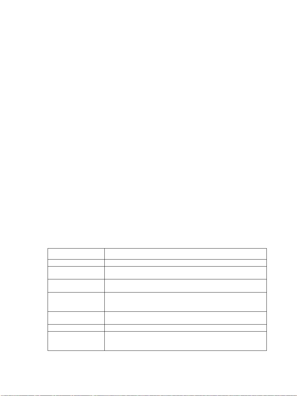
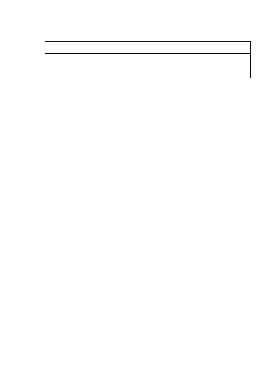
with any suggestions or questions you may have. The following table lists the data
acquisition controls in SoftWIRE that require the UL software support components:
SoftWIRE Control
Analog In
Analog In Scan
Analog In Trigger
Analog In PreTrigger
Set Trigger
Analog Out
Analog Out Scan
Description
The Analog In control reads the data from an analog input channel.
The Analog In Scan control scans a range of analog input channels and
transfers the samples in the form of an array
The Analog In Trigger control outputs an analog input value when it
goes above or below a specified trigger value.
The Analog In PreTrigger control causes an analog input board to wait
for a trigger to occur and then returns a set number of analog samples
before and after the trigger occurred.
The Set Trigger control allows you to specify and set up a trigger source
that starts a scan function using certain Data Acquisition controls.
The Analog Out control writes data to an analog output channel.
The Analog Out Scan control sends a specified number of analog
output data samples to a specific board over a range of analog output
channels.
8
Page 14
Universal Library User's Guide Universal Library Description & Use
Digital In
Digital Bit In
Digital Out
The Digital In control reads a value from a specified board and digital
input port.
The Digital Bit In control reads the value, or state, of a single digital
input bit.
The Digital Out control sets the digital output value for a specified
board and port.
2.5 Using the Library with DOS Basic
Each of the supported versions of BASIC consists of two distinct systems. Programs can be
loaded into the BASIC editor and run from within the integrated BASIC environment.
Programs can also be compiled by a command line compiler into stand-alone executable
programs that can be run on their own without the help of the integrated BASIC
environment. The Universal Library provides the tools for both methods.
BASIC Header File
Every BASIC program that uses the Universal Library must have a line which includes the
BASIC Universal Library header file - CB.BI. The following line should appear near the
start of every program, before the first library call is made.
'$INCLUDE: 'CB.BI'
Using Universal Library Within The Integrated BASIC Environment
When you start up BASIC, specify that you want to load the "quick library" version of
Universal Library. For Quick BASIC type:
qb /l cbqb
For Professional BASIC type:
qbx /l cbpb
For Visual Basic for DOS, type:
vbdos /l cbvb
Using The Library With The BASIC Command Line Compiler
To build stand-alone executable files with the command line compiler, you must link your
compiled BASIC program with the stand-alone version of the Universal Library. To do this,
you must supply the linker with the library name.
The names of the .lib files are:
• QuickBasic CBQB.LIB
• Professional Basic CBPB.LIB
• Visual Basic for DOS CBVB.LIB
9
Page 15

Universal Library User's Guide Universal Library Description & Use
Sample Basic Programs
The sample BASIC programs included demonstrate how to call each function in the
Universal Library. These programs can be run from within the integrated BASIC
environment. They can also be compiled using the command line compiler with the batch
file supplied. The names of the batch files are:
• QuickBasic MAKEQB.BAT
• Professional BASIC MAKEPB.BAT
• Visual Basic for DOS MAKEVB.BAT
Passing Arguments to Universal Library
All of the functions in the library require that arguments be passed to them. The file CB.BI
contains the definition of all the argument types that are passed. In general, there are two
classes of arguments, inputs and outputs.
Input Arguments
All arguments that are only used as inputs to a library function are listed in the CB.BI file
definition as BYVAL. For these arguments, you can pass either a variable or a constant. So for
example, both of these versions are acceptable:
BoardNum% = 0
cbStopBackground (BoardNum%)
or
cbStopBackground (0)
Output Arguments
Some arguments are used by the library to pass information back to the caller. For example,
the value from an A/D is returned by cbAIn() to the DataValue% argument. Others are used
as both inputs and outputs. For example, the Rate& argument specifies the requested
sampling rate for cbAInScan() (Input).
The actual sampling rate can vary from the requested sampling rate so the actual rate is
returned by cbAInScan() to the Rate& argument (Output).
Output and Input/Output arguments are defined in the CB.BI function definitions as SEG. All
SEG arguments can only be passed via a variable. For example:
Count& = 1000
Rate& = 15000
cbAInScan (0, 0, 1, Count&, Rate&, BIP5VOLTS, DataArray(0), 0)
is correct, but,
cbAInScan (0, 0, 1, 1000, 15000, BIP5VOLTS,DataArray(0), 0)
is NOT correct.
10
Page 16

Universal Library User's Guide Universal Library Description & Use
DataArray Argument with Multiple Channels
Various functions have a DataArray argument. The DataArray either receives the data from
an input function such as cbAInScan(), or contains the data to be sent to an output function
such as cbAOutScan().
The DataArray must be dimensioned to be large enough to contain all of the data. The array
can either be dimensioned with a single dimension or two dimensions. When sampling more
than one channel, it is often more straightforward to use a multiple dimensioned array. The
code below shows both methods:
DIM DataBuffer (1999) 'One-dimensional array. 0 to 1,999
(2,000) elements.
or
DIM DataBuffer (1, 999) 'Two-dimensional array. 0 & 1 with 0999 (1,000) elements each.
LowChan% = 2
HighChan% = 3
Count& = 2000
Rate& = 1000
cbAInScan (0, LowChan%, HighChan%, Count&, Rate&, BIP5VOLTS,
DataBuffer(0), 0)
or
cbAInScan (0, LowChan%, HighChan%, Count&, Rate&, BIP5VOLTS,
DataBuffer(0, 0), 0)
The advantage of using the multi-dimensioned array is that you can directly address the data
in the array by channel. Therefore, in the example above, DataBuffer (0, 99) addresses
the 100th sample for channel 2 (channel 2 was the first element in the array; LowChan%).
Using String Arguments
cbGetErrMsg() requires that a string variable be passed as an argument. This string
variable must have been previously allocated to be large enough to hold the longest error
message. To do this use Quick BASIC's space$ function as it is done in the example
program.
ErrStr$ = space$ (ERRSTRLEN)
Integer Arguments
BASIC does not support unsigned integers (0 to 65,535). Values for the integer data type
range from −32,768 to 32,767. When using functions that require unsigned integers, the data
must be converted. See section 2.2.
11
Page 17

Universal Library User's Guide Universal Library Description & Use
BACKGROUND operation
If you use the BACKGROUND option with any function, you must declare the associated data
array as '$STATIC.
Unless you declare an array as '$STATIC, BASIC may move the array around in memory as
the program is executing. Whenever you use the BACKGROUND option, the I/O function
reads/writes from the data array in the background while the BASIC program continues
executing in the "foreground.” If BASIC moves the array while the I/O function is
reading/writing to it, it will cause intermittent and unpredictable problems.
cbStopBackground() should be executed after normal termination of all background
functions to clear variables and flags.
2.6 Using the Library with Visual Basic for DOS
Compiling Stand Alone EXE files
Due to a quirk in Visual Basic for DOS, if you compile a stand-alone EXE file from within
the IDE and you set the EXE type to "Stand alone EXE file", you will get the following
message:
"fixup overflow at 334 in the segment -TEXT target external
'B$CEND'".
The compiled program will run without error. It appears that the error message is an error.
2.7 Using the Library with C for DOS
The C libraries included with the system can be used with either the Microsoft or Borland C
compilers.
C Header File
Every C program that uses the Universal Library must have a line which includes the
Universal Library C header file, CB.H. The following line should appear near the start of
every program, before the first library call is made.
#include "cb.h"
Memory Models
Both Borland and Microsoft C compilers support different memory models. The Universal
Library comes with the following four versions of the library.
CBCC.LIB - For use with compact model
12
Page 18

Universal Library User's Guide Universal Library Description & Use
CBCS.LIB - For use with small model
CBCM.LIB - For use with medium model
CBCL.LIB - For use with large and huge model
Large Data Arrays
The Universal Library supports input and output from very large (>64K) amounts of data. If
your program requires storage and transfer of large single data sets, you must compile it for
the "huge" model and use the CBCL.LIB library. If you declare an array to hold the data, it
should be declared __huge.
If you allocate memory (as is done in the example programs using malloc) it should be
allocated using _halloc (Microsoft) or halloc (Borland), the pointer declared as __huge
and memory freed using _hfree (Microsoft) or hfree (Borland). Note that you must also
include the malloc.h header.
Compiling The Sample C Programs
The example programs demonstrate how to call each of the Universal Library functions
from a C program. Two batch files are provided that show how to compile and link the
sample programs using the Microsoft and Borland compilers.
MAKEMC16.BAT - compile and link with Microsoft C
MAKETC16.BAT - compile and link with Borland C
2.8 Using the Library with HP VEE
The Universal Library For HP VEE includes a complete interface to HP VEE providing a
DataAcq specific menu bar addition and functions as well as complete example of all the
library functions.
To understand how the interface to HP VEE interacts with I/O boards, you need to study
both this manual and the example programs. This manual is written for symbolic
programming languages such as BASIC and C. VEE is a graphical programming language.
It is very important that you scan the entire manual for information that relates to general
performance. Remember, VEE is using the Universal Library as the interface to the I/O
boards; the entire library. Limitations and performance factors in the library are reflected in
VEE programs that use the library. The manual contains much related information, like
most manuals, scattered throughout. We encourage you to review the entire manual.
The Universal Library interface to VEE follows the structure of the library as it is used with
all other languages. The arguments presented here in symbolic format are the same
arguments you will need to specify when using VEE to control an I/O board. The manual
13
Page 19

Universal Library User's Guide Universal Library Description & Use
explains the functions and each of the arguments. The VEE examples show how the
function is interfaced to VEE and show how to use the function to control the I/O boards.
There is one exception to this rule. The programming argument MemHandle is replaced in
VEE with the argument DataArray. VEE allocates data arrays directly. Windows
programming languages use another method of pointing to data arrays. In addition to a name
change, there is some VEE programming logic done to dimension a two-dimensional data
array for all multichannel operations. This logic can be seen by examining the design view
of the function.
Each function is implemented as a panel. All the arguments are accessible on the panel and
require a value. In the example programs and in simple projects this method of presenting
the functions is easiest to use. Each value is hard-coded into the panel.
If more complex projects are undertaken, open the design view of the function and drag
certain arguments outside the panel. Dragging an object outside the panel will create a 'pin'
to which you can connect constants, variables, or objects such as slider bars. In large
projects the ability to supply an argument with a variable that acquires its value elsewhere is
especially useful. See the VEE manual for information on how to do this.
See the example ULAI06.VEE for an example of multiple use of several arguments where it
is better to specify the argument values globally. In this example, we have brought several
arguments out of the panel
Remember, if you drag an argument outside a panel you must reconnect the program flow
(top and bottom pins) of the remaining arguments; the one above to the one below the
argument you removed.
New HP VEE Functions
Several new functions have been added strictly for use with HP VEE. These functions are
listed separately in a section devoted to the VEE specific functions. All VEE specific
functions begin with the name cbv, rather than cb . The new functions add VEE style data
and array handling to the library.
Using the HP VEE interface is simple and a great way to connect your VEE programs to the
real world. Read the manual, start with the examples, then begin working up your own
projects. Remember to call us with suggestions!
Must Install Universal Library in Default Directory
The HP VEE library import block CBI_UL contains an exact path specification for the
library CBV.DLL and its header file CBV.H. If you do not install these files into the default
directory suggested by the install program you will have to edit the library import block
CBI_UL to point to the directory where the files are installed.
To edit the library import block, click on the DataAcq menu item then click on its cbLibrary
sub-menu item. Place the mouse cursor at the desired location for the library import block
14
Page 20

Universal Library User's Guide Universal Library Description & Use
and press the left mouse button once. Double click the library import block object. A
detailed CBI_UL library block will be displayed. Within the CBI_UL library block, click on
the button to the right of File Name. Enter the new path with the file name and click OK.
Next click on the button to the right of Definition File. Enter the new path with the file name
and click OK.
Using VEE 3.2 or Later
If you are using VEE 3.2 or later, please edit the library import block and change the library
name from CBV.DLL to CBV32.DLL. Be sure to include the proper path.
2.9 File Functions Overview
One of the features of the Universal Library is the ability to collect very large amounts of
data to a "streamer" file. The amount of data that can be collected is limited only by the size
of your hard disk.
After all of the data has been streamed to a file, your program can read it back into arrays
and process it in chunks. This feature is particularly useful with Universal Library from
DOS, where memory is limited.
The library contains four functions that are used with "streamer" files. cbFileAInScan()
and cbFilePretrig() read the A/D and store the data in a "streamer" file.
cbFileGetInfo() returns information about the streamer file. cbFileRead() reads data
from a "streamer" file to an array.
In addition to these library functions, the library comes with three utility programs for use
with the 16-bit version of the library; MAKESTRM.EXE, FRAGTEST.EXE and
RDSTREAM.EXE. These utilities are not compatible with the 32-bit version of the library.
MAKESTRM creates a "streamer" file. This program should be run to allocate a file large
enough to hold all of the data that will be later collected with cbFileAInScan() or
cbFilePretrig(). The syntax is:
C:\MAKESTRM filename # <enter>
FRAGTEST checks an existing disk file to see if it is fragmented. In order to run at the
faster sampling rates, the "streamer" file must not be fragmented. Refer to "Speeding up
Disk Files" below for more information. The syntax is:
C:\FRAGTEST filename <enter>
RDSTREAM reads a "streamer" file and prints its contents on the screen. The syntax is:
C:\RDSTREAM filename <enter>
15
Page 21

Universal Library User's Guide Universal Library Description & Use
2.10 Hard Disk VS RAM Disk Files
The simplest type of file to use is a standard DOS file on a hard disk. The advantage of hard
disk files is that they can be very large. The file size is only limited by the amount of free
space on the disk. Hard disk files have the disadvantage of being slower than RAM disks.
RAM disk (or virtual disk) files are faster but they are limited in size by the amount of
available memory in your computer.
2.11 Maximum Sampling Speed
The maximum sustainable sampling rate that can be specified with the cbFile functions is
very hard to predict. It depends on the speed of the CPU and the speed of the disk.
In addition to the variation in sampling speed from machine to machine, there can also be
variations on the same machine between consecutive operations of the same program. When
reading an A/D to memory (non-streaming modes) there is a hard and fast maximum
sampling speed that cannot be exceeded. When using the streaming modes the maximum
rate is much fuzzier and must be arrived at by trial and error.
A rough guideline of attainable speeds are that on a 33 MHz 80386 machine with a fast hard
disk it should be possible to collect a megabyte of data at 200 kHz sampling rate to a disk
file. It should also be possible to collect a megabyte of data to a RAM disk at 330 kHz.
In general the maximum sustainable speed for cbFilePretrig() will be somewhat less
than for cbFileAInScan().
Another characteristic of these "streaming" modes is that the more data you collect the
lower the maximum speed will be. On any machine with any speed disk, you can collect
32000 samples to a disk file at the maximum A/D speed of 330 kHz. If you are pushing the
upper limits of speed you will find that you can collect 100K samples at a faster rate than
you can collect 500K samples, etc.
2.12 How To Determine Maximum Sampling Speed
The only way to determine the maximum safe speed is to try it repeatedly. Remember, if it
works the first time it will not necessarily work the next time. Therefore, the only way to be
sure that you can reliably run at a particular speed is to try it numerous times. Another
method is to increase the speed to the point where it begins to fail every time so that you get
some sense of whether or not you are pushing the speed limit on your computer.
To test it, write a program that calls cbFileAInScan() or cbFilePretrig() (depending on
whether you need pre-trigger data). Check the returned error code. If you get an OVERRUN
error (error code of 29), it means that the sampling rate is too high. Whenever you get
OVERRUN error, some data was collected but not all of it. It is often useful to check how
much data was collected to find out whether it was almost fast enough or not even close.
16
Page 22

Universal Library User's Guide Universal Library Description & Use
2.13 Speeding Up Disk Files (De-fragmenting)
Because of the way that disks work, the time that it takes to write to them can vary
tremendously. A large disk file is made up of many small pieces that are written
individually to the disk. If the file is contiguous (each piece is side by side) the speed is very
fast. If the file is fragmented (pieces are in different places on the disk) the speed is much
slower. If you create a large disk file, the odds are overwhelming that it will be fragmented
to some degree and the maximum sampling speed will be much lower than it would be for
an unfragmented file.
To get around this problem you should use a Disk Optimizer or De-Fragmenter program
immediately before creating the streamer file with MAKESTRM. After you create the
streamer file, it will remain unfragmented so long as you do not erase and recreate it.
Probably the most widely known Disk Optimizer program comes as part of the Norton
Utilities, it is called Speed Disk or SD. To run it type:
SD /Q
This will execute the "Quick" optimize, which for these purposes works as well as the Full
Optimization.
After de-fragmenting the disk create a streamer file that is large enough to hold as much
data as you plan to collect with cbFileAInScan() or cbFilePretrig(). To create the disk
file run the standalone MAKESTRM.EXE program. This will create a streamer file of the
required size.
After the file is created, run FRAGTEST.EXE to see whether or not the file is fragmented. It
is possible that the file may be fragmented even though you just de-fragmented the disk.
The reason for this is that the disk may contain some bad sectors which could not be moved
when the disk was optimized. When you create the new file if it hits one of these bad sectors
it has to skip over it, hence fragmentized.
If FRAGTEST reports that the file is fragmented, create a second file and test that with
FRAGTEST. Repeat this until FRAGTEST reports that the file is OK. After you have an
unfragmented disk file you can try using it with cbFileAInScan() or cbFilePretrig() to
collect data. If the maximum sampling speed is still too slow, you should probably switch to
a RAM disk.
2.14 What is a RAM Disk?
A RAM disk is not really a disk. It is a device driver that sets aside some of the computer's
memory and makes it appear to DOS as a disk drive. When you install a RAM disk on your
computer it appears exactly as if you have another VERY fast hard disk drive. For example,
if you have one hard disk (drive C:) then when you install the RAM disk it will appear as if
you have another hard disk, drive D.
17
Page 23

Universal Library User's Guide Universal Library Description & Use
After the RAM disk is installed, all DOS commands work exactly the same on the RAM
disk as on the hard disk. For example you can COPY, DEL, MKDIR, CD just as you would
on a hard disk.
2.15 Installing a RAM Disk
The RAM disk driver comes with DOS. Refer to your DOS manual for more information. In
older versions of DOS it is called either RAMDRIVE.SYS or VDISK.SYS. To install it you
must add one line to your \CONFIG.SYS file. Find which directory the DOS files are
installed in on your machine. CD to that directory and look for a file called
RAMDRIVE.SYS or VDISK.SYS. If it is not there look at the other .SYS files in the
directory and refer to your DOS manual to find out if any of them are a RAM Disk driver.
After you have located the file add an entry to the \CONFIG.SYS file.
If the RAMDRIVE.SYS file was in a directory called DOS then you would add the
following line to the \CONFIG.SYS file.
device=c:\dos\ramdrive.sys
The default size for the RAM disk is usually 64K. You will almost certainly want to make it
larger than that. The larger you make it the more data you can collect but the less memory
will be available for other programs.
To set up a 4 megabyte RAM disk you would add the following line to your CONFIG.SYS
file:
device=c:\dos\ramdrive.sys 4000
If your computer is an 80x86 then you should install the RAM disk in extended memory
(above 1M) by specifying the /e option:
device=c:\dos\ramdrive.sys 4000 /e
After you add the new line to the \CONFIG.SYS file, reboot the computer (Press CTRLALT-DEL) to install the RAM disk. When the machine reboots it should print a message on
the screen describing the RAM disk.
2.16 Using the RAM Disk
To use the RAM disk you just specify the drive letter in the FileName argument of
cbFileAInScan() or cbFilePretrig(). For example if the RAM disk is drive D: on your
system then you could set the name of the "streamer" file in your program to
"D:TEST.DAT"
This file can be created with the MAKESTRM.EXE program supplied with the Universal
Library.
18
Page 24

Universal Library User's Guide Universal Library Description & Use
To set up a file large enough to hold 1 million samples, include this line in your
AUTOEXEC.BAT file:
C:\CB\MAKESTRM D:\TEST.DAT 1000000
The name TEST.DAT is an example. Use the name of your preference.
When you execute cbFileAInScan() or cbFilePreTrig() it will fill up the file on your
RAM drive. This file will be lost as soon as the power is switched off so if you wish to keep
the data you must copy it to the hard disk before turning the computer off.
19
Page 25

Analog Input Boards Introduction
3 Analog Input Boards
3.1 Introduction
All boards that have analog input support the cbAIn() and cbAInScan() functions (except
expansion boards which support cbAIn() only). Boards released after the printing of this
manual are described in readme files on the Universal Library disk.
In cases where hardware-paced A/D conversion is not supported, cbAInScan() loops
through software paced conversions. The scan will execute at the maximum speed possible.
This speed will vary with CPU speed. The only valid option in this case is CONVERTDATA.
If trigger support is 'Polled gate' (as opposed to 'Hardware'), this indicates that the 'trigger' is
implemented by disabling the on-board pacer by gating it. The trigger input is then polled
continuously until the trigger occurs. When that happens, the software disables the gate
input so that when the trigger returns to its original state, it does not affect the pacer and
acquisition continues until the requested number of samples has been acquired. There are
two 'side effects' to this type of trigger:
1) The polling portion of the function does not occur in the background even if the
BACKGROUND option was specified (although the actual data acquisition does).
2) The trigger does not necessarily occur on the rising edge. Acquisition can start at any
time after the function is called if the trigger input is at 'active' level. For this reason, it is
best to use a trigger that goes active for a much shorter time than inactive.
Similar to ‘Polled gate’ triggering is ‘Polled digital input’ triggering. For this trigger type,
the pacer is disabled while the state of a digital input is polled. When the state changes to
active, the pacer is enabled by the software. The polled digital input trigger type limitations
are very similar to the polled gate type described above.
Sampling rate using SINGLEIO
When using this mode of data transfer, the maximum analog sampling rate is dependent on
the speed of the computer in which the board is installed. In general, it is somewhere in the
range of 5 to 50 kHz. If the speed you request cannot be sustained, an overrun error will
occur. Data will be returned, but likely there will be gaps. Some boards, such as the CIO-
DAS08, support only this mode. Thus, the maximum rate attainable with these boards is
system-dependent.
20
Page 26

Analog Input Boards PCI-DAS6000 Series
3.2 PCI-DAS6000 Series
q Analog Input
Analog Input Functions Supported
cbAIn(), cbAInScan(), cbATrig(), cbAPretrig(), cbFileAInScan(),
cbFilePretrig(), cbALoadQueue()
Analog Input Argument Values
Options BACKGROUND, CONTINUOUS, EXTCLOCK, CONVERTDATA,
SINGLEIO, BLOCKIO, BURSTMODE, EXTTRIGGER
HighChan 0 to 15 in single-ended mode, 0 to 7 in differential mode
Rate Up to 200000
Range PCI-DAS6023, PCI-DAS6025, PCI-DAS6034, PCI-DAS6035
BIP10VOLTS
BIP5VOLTS
BIPPT5VOLTS
BIPPT05VOLTS
q Analog Output
PCI-DAS6025, PCI-DAS6035 only
Analog Output Functions Supported
cbAOut(), cbAOutScan()
Analog Output Argument Ranges
Options BACKGROUND, CONTINUOUS, EXTCLOCK, SIMULTANEOUS
HighChan 0 to 1
Rate Up to 10000
Range BIP10VOLTS
DataValue 0 to 4095
21
Page 27

Analog Input Boards PCI-DAS6000 Series
q Digital I/O
Digital I/O Functions Supported
cbDOut(), cbDIn(), cbDBitIn(), cbDBitOut(), cbDConfigBit(),
cbDConfigPort()
Digital I/O Argument Values
PortNum AUXPORT
DataValue 0 to 255
BitNum 0 to 7
For PCI-DAS6025, the following additional argument values are also valid
PortNum FIRSTPORTA, FIRSTPORTB, FIRSTPORTCL, FIRSTPORTCH
DataValue 0 to 15 for PORTCL or PORTCH;
0 to 255 for PORTA or PORTB
BitNum 0 to 23 for FIRSTPORTA
q Counter I/O
Counter Functions Supported
cbC8254Config(), cbCIn(), cbCLoad()
Counter Argument Values
CounterNum 1 to 2
Config HIGHONLASTCOUNT, ONESHOT, RATEGENERATOR, SQUAREWAVE,
SOFTWARESTROBE, HARDWARESTROBE
LoadValue 0 to 65535 (see notes on unsigned integers in Section 2.2.)
q Triggering
Trigger Functions Supported
cbSetTrigger()
Trigger Argument Values
TrigType GATE_HIGH, GATE_LOW, TRIG_POS_EDGE, TRIG_NEG_EDGE
22
Page 28

Analog Input Boards PCI-DAS6000 Series
q Event Notification
Event Notification Functions Supported
cbEnableEvent(), cbDisableEvent()
Event Notification Argument Values
EventType ON_SCAN_ERROR, ON_PRETRIGGER*, ON_DATA_AVAILABLE,
ON_END_AI_SCAN
For PCI-DAS6025, PCI-DAS6035, the following additional
argument value is also valid
ON_END_OF_AO_SCAN
q Hardware Considerations
Pacing Analog Input
Hardware pacing, external or internal clock supported. When using
EXTTRIGGER, the clock edge is selectable through InstaCal.
When using EXTCLOCK and BURSTMODE together, do not use the A/D
External Pacer to supply the clock. Use the A/D Start Trigger input
instead. Since BURSTMODE is actually paced by the internal burst clock,
specifying EXTCLOCK when using BURSTMODE is equivalent to specifying
EXTTRIGGER.
The clock edge used to trigger acquisition for the external pacer may be
rising or falling and is selectable using InstaCal.
The packet size is 512 samples.
Analog Input Configuration
The analog input mode may be 8 channel differential, 16 channel singleended referenced to ground or 16 channel single-ended non-referenced
and may be selected using InstaCal.
Triggering & Gating
Digital (TTL) hardware triggering is supported for the entire series.
When using cbAPretrig() or cbFilePretrig() , use the A/D Stop
Trigger input to supply the trigger.
Gain queue
When using cbALoadQueue(), up to 8k elements may be loaded into the
queue.
23
Page 29

Analog Input Boards PCI-DAS6000 Series
Pacing Analog Output
Hardware pacing, external or internal clock supported.
Digital Input/Output Configuration
AUXPORT is bitwise configurable for these boards, and must be configured
using cbDConfigBit() or cbDConfigPort() before use.
Counters
The source for counters 1 and 2 may be internal 10MHz, internal 100kHz
or external and is selectable using InstaCal.
Event Notification
Note that the EventData for ON_PRETRIGGER events may not be accurate.
In general, this value will be below the actual number of pretrigger
samples available in the buffer.
24
Page 30

Analog Input Boards PCI-DAS4020 Series
3.3 PCI-DAS4020 Series
q Analog Input
Analog Input Functions Supported
cbAIn(), cbAInScan(), cbATrig(), cbAPretrig(), cbFileAInScan(),
cbFilePretrig()
Analog Input Argument Values
Options BACKGROUND, CONTINUOUS, EXTCLOCK, CONVERTDATA,
SINGLEIO, DMAIO, BLOCKIO, EXTTRIGGER
HighChan 3 max (when scanning multiple channels, the number of channels
scanned must be even)
Rate Up to 20000000 (Contiguous memory may be required to achieve
maximum performance. See details below.)
Range BIP5VOLTS
BIP1VOLTS
q Analog Output
Analog Output Functions Supported
cbAOut(), cbAOutScan()
Analog Output Argument Ranges
Options NONE
HighChan 1 max
Count 2
Rate Ignored
Range BIP10VOLTS
BIP5VOLTS
DataValue 0 to 4095
25
Page 31

Analog Input Boards PCI-DAS4020 Series
q Digital I/O
Digital I/O Functions Supported
cbDOut(), cbDIn(), cbDBitIn(), cbDBitOut(), cbDConfigPort()
Digital I/O Argument Values
PortNum FIRSTPORTA, FIRSTPORTB, FIRSTPORTCL, FIRSTPORTCH
DataValue 0 to 15 for PORTCL or PORTCH
0 to 255 for PORTA or PORTB
BitNum 0 to 23 for FIRSTPORTA
q Counter I/O
Counter Functions Supported
None
q Triggering
Trigger Functions Supported
cbSetTrigger()
Trigger Argument Values
TrigType TRIG_POS_EDGE, TRIG_NEG_EDGE, TRIGABOVE, TRIGBELOW,
GATEHIGH, GATELOW, GATENEGHYST, GATEPOSHYST, GATEABOVE,
GATEBELOW, GATEINWINDOW, GATEOUTWINDOW
Threshold 0 to 4095
q Event Notification
Event Notification Functions Supported
cbEnableEvent(), cbDisableEvent()
Event Notification Argument Values
EventType ON_SCAN_ERROR, ON_PRETRIGGER, ON_DATA_AVAILABLE,
ON_END_OF_AI_SCAN
26
Page 32

Analog Input Boards PCI-DAS4020 Series
q Hardware Considerations
Pacing Analog Input
Hardware pacing, external or internal clock supported. The clock source
can be set via InstaCal to either the "Trig/Ext Clk" BNC input or the
"A/D External Clock" input on the 40 pin connector (P3). Configuring for
the BNC clock input will disable the clock input (pin 10) on the 40-pin
connector.
When EXTCLOCK option is used, the clock signal presented to the
"Trig/Ext Clk" BNC input or the "A/D External Clock" input is divided
by 2 by the prescaler. This value is currently fixed at 2 in the Universal
Library. If both EXTCLOCK and EXTTRIGGER are used, both the Trigger
BNC and pin 10 on the 40-pin connector require signals. This is further
explained in the Triggering section following. When using EXTCLOCK, the
Rate argument IS USED by the Universal Library to calculate the
appropriate chain size; please set the Rate argument to the approximate
rate that the external clock will be pacing acquisitions.
The packet size varies. See Memory Configuration below.
Triggering & Gating
Digital (TTL) hardware triggering supported. The trigger source can be
set via InstaCal to either the "Trig/Ext Clk" BNC input, the "A/D Start
Trigger" input on the 40-pin connector (P3) or the "A/D Stop Trigger"
input on the 40-pin connector (P3). Use the A/D Start Trigger input for
cbAInScan() and cbFileAInScan() functions. For cbAPretrig() or
cbFilePretrig() functions, use the A/D Stop Trigger input.
When using both EXTCLOCK and EXTTRIGGER options, one of the signals
(either clock or trigger) must be assigned to the Trig/Ext Clk BNC input.
The function of the Trigger BNC is determined by the setting of "Trig/Ext
Clock Mode" in InstaCal. The Trig/Ext Clock BNC can be set to function
as either the trigger ("A/D Start Trigger") or the clock ("A/D External
Clock"). Pin 10 on the 40-pin connector then assumes the opposite
function.
Analog hardware triggering supported. The trigger source can be set via
InstaCal to any of the analog BNC inputs. cbSetTrigger() is supported
for TRIGBELOW and TRIGABOVE trigger types. Analog thresholds are set
relative to the voltage range set in the scan. For example, using a range of
BIP1VOLTS during a cbAInScan(), (0) corresponds to −1V and 4095
corresponds to +1V.
27
Page 33

Analog Input Boards PCI-DAS4020 Series
When using the cbAPretrig() function, use either the TRIGGER BNC
or Pin 8 of the 40 pin connector. To use the BNC, set InstaCal "Trig/Ext
Clock Mode" to A/D Stop Trigger; otherwise, if not set to this selection,
Pin 8 of the 40-pin connector is used.
When using cbAPretrig() with EXTCLOCK, the two inputs are required.
The TRIGGER BNC can be set to function as either the pacer clock or
the trigger. For the BNC to be setup as the pacer clock, set InstaCal
"Trig/Ext Clk Mode" to A/D External Clock. To use the BNC as the
trigger, set this InstaCal option to A/D Stop Trigger. If neither of these
selections are used, the 40-pin connector will be used for both inputs; Pin
8 will be input for A/D Stop Trigger, and Pin 10 will be input for the
pacer clock signal.
Digital (TTL) hardware gating supported. The gate source can be set via
InstaCal to either the "Trig/Ext Clk" BNC input or the "A/D Pacer Gate"
input on the 40-pin connector (P3).
Analog hardware gating supported. Analog thresholds are set relative to
the voltage range set in the scan. For example, using a range of
BIP1VOLTS during a cbAInScan(), (0) corresponds to (−1V) and 4095
corresponds to +1V.
The gate must be in the active (enabled) state before starting an
acquisition.
For EXTCLOCK or EXTTRIGGER (digital triggering) using the BNC
connector, InstaCal provides a configuration setting for thresholds. The
selections available are either 0 Volts or 2.5 Volts. Use 0 Volts if the
incoming signal is BIPOLAR. Use the 2.5 Volts option if the signal is
UNIPOLAR, i.e., standard TTL.
Memory Configuration
In order to achieve the maximum sample rate under some conditions, a
contiguous area of memory must be set up. The following is a guide that
can be used to determine whether or not you need to set up this memory
and how to accomplish it using InstaCal.
If the number of samples you are acquiring is less than 2K (2,048)
samples then you do NOT need to set up contiguous memory (the
"Contiguous Mem" edit box in InstaCal can be left at zero).
If you are acquiring more than 2048 samples, contiguous memory may be
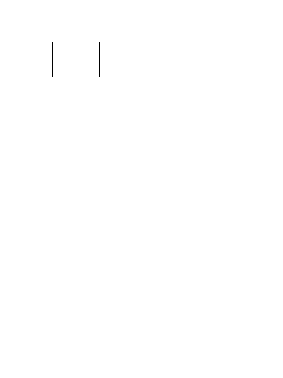
required depending on sample rate. Use the table below to determine if
contiguous memory is required.
28
Page 34
Analog Input Boards PCI-DAS4020 Series
# of Channels Rate Requiring Contiguous Memory (when sample count >
2048)
1 > 4 MHz
2 >2 MHz
4 >1 MHz
If Contiguous Memory is required, follow the InstaCal procedures below:
1.) Run InstaCal, select the PCI-DAS4020 board and click the
"Configure" tab.
2.) In the "Memory Size" edit box for the Contiguous Memory Settings,
type in the amount of memory in kilobytes that you need for the
acquisition. To calculate the number of kilobytes required use the
following formula:
(# of KB) = {(# of samples) x (2 bytes/sample) x (1 KB/1024 bytes)},
or
(# of KB) = {(# of samples)/512} .
Note that memory is allocated in blocks of 4 KB. As a consequence,
InstaCal will adjust the amount entered upward to the nearest integer
multiple of 4 KB.
For example, the contiguous memory requirements for a 10,000 sample
acquisition would be:
(10,000/512) = 19.5 rounded up to multiple of 4 kBytes = 20 KB.
Note that the maximum number of samples allowed for the given
contiguous memory size is displayed as the "Sample Count" below the
"Memory Size" edit box.
3) Reboot the machine. The Universal Library will attempt to reserve the
contiguous memory at bootup time. If it is unable to reserve all the
memory requested, the amount successfully reserved will be displayed in
the Memory Size entry when InstaCal is run again.
4) After rebooting your PC, please run InstaCal to verify the size of the
Contiguous Memory that was successfully reserved.
5) To change or free the contiguous memory, repeat step 1 through 4
specifying the new size.
Note that the size of the block shown in InstaCal is the TOTAL
CONTIGUOUS MEMORY available to ALL BOARDS INSTALLED.
Other boards in the PC using the Universal Library's cbWinBufAlloc()
29
Page 35
Analog Input Boards PCI-DAS4020 Series
function will also use this contiguous memory, so plan the size of the
contiguous memory buffer accordingly.
There are two special cases where you need to be aware of packet size
and adjust the number of samples acquired accordingly:
1.) cbAPretrig()
2.) cbAInScan with the CONTINUOUS scan option
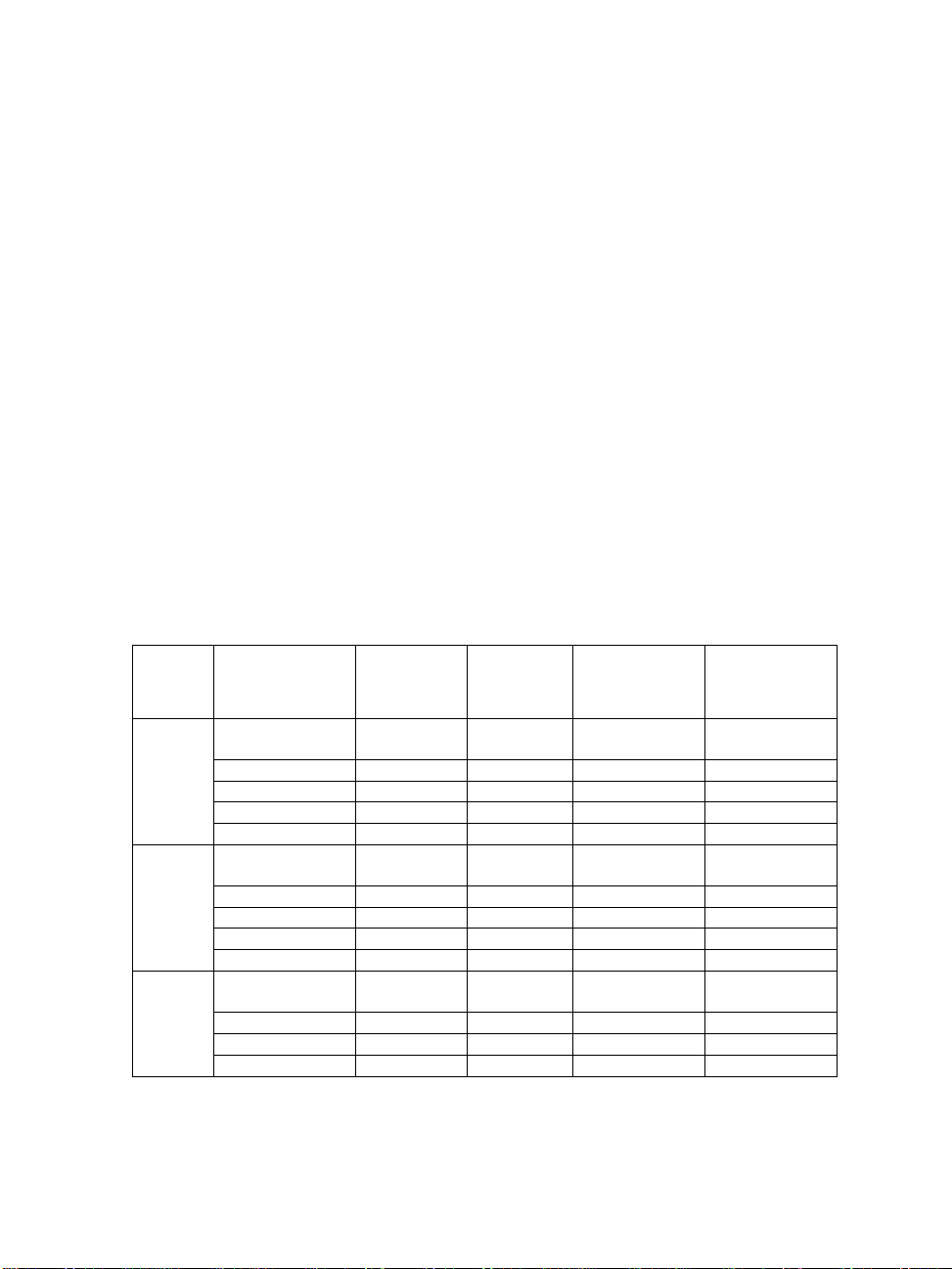
These functions use a circular buffer. The data must be aligned in the
buffer by packets for these functions. For both cases, the total number of
samples must be greater than one packet (listed in the table below) and
must be an integer multiple of packet size. In addition, contiguous
memory must be used if noted in the table below. The minimum value for
contiguous memory is calculated using the formula in step 2 above:
( # of KB ) = {( # of samples ) / 512}
As an example, to run cbAInScan on one channel at 18MHz with the
CONTINUOUS option set, determine the minimum sample size from the
chart to be 262,144 (since the Rate is between 14 and 20MHz). The
minimum contiguous memory is calculated as follows:
(262,144 / 512 ) = 512 KB
Number
of
Channels
1
Rate in MHz Packet Size
20 >= Rate
>=13.3
13.3 > Rate >= 4 65,536 131,072 Required 256 KB
4 > Rate >= 2 4,096 8,192 Not Required 0 KB
2 > Rate 2,048 4,096 Not Required 0 KB
in Samples
131,072 262,144 Required 512 KB
Minimum
Sample Size
(two
packets)
Contiguous
Memory
Min Contiguous
Memory
(based on Min
Sample Size)
2
4
20 >= Rate >=
6.6
6.6 > Rate >= 2 65,536 131,072 Required 256 KB
2 > Rate >= 1 4,096 8,192 Not Required 0 KB
1 > Rate 2,048 4,096 Not Required 0 KB
20 >= Rate >=
3.3
3.3 > Rate >= 1 65,536 131,072 Required 256 KB
1 > Rate >= 0.5 4,096 8,192 Not Required 0 KB
0.5 > Rate 2,048 4,096 Not Required 0 KB
131,072 262,144 Required 512 KB
131,072 262,144 Required 512 KB
30
Page 36

Analog Input Boards PCI-DAS4020 Series
*Note that the EventData for ON_PRETRIGGER events may not be
accurate. In general, this value will be below the actual number of
pretrigger samples available in the buffer.
q Notes for SoftWIRE Users
Memory Configuration
The Analog In Scan control may require more contiguous memory than
listed in the prior table When the CONTINUOUS option is set for the Analog
In Scan control, the control allocates a buffer large enough to hold four
times as much data as required for a single scan. As a consequence, if you
will be running CONTINUOUS scans with the Analog In Scan control, you
will need to allocate a minimum of four times that shown in the table
above. For example, using the Analog In Scan control to run a
CONTINUOUS scan of one channel at 18 MHz will require a minimum scan
Count Per Channel of 262,144 samples, but will require at least 2048 KB
(= 4*262144/512 KB) of contiguous memory.
The Analog In PreTrigger control may require more contiguous memory
than listed in the prior table. When the Analog In PreTrigger control is
run, it allocates a buffer that will hold 512 samples larger than requested
by the user. As a consequence, when contiguous memory is required for
the scan, the Analog In PreTrigger control will require an extra 4 KB
worth of contiguous memory be allocated. For example, using the Analog
In PreTrigger control to run a scan with one channel at 18 MHz will
require a minimum Count Per Channel of 262,144 samples, but will
require at least 516 KB (= 512 KB + 4KB) of contiguous memory.
31
Page 37

Analog Input Boards PCI-DAS64/Mx/16 Series
3.4 PCI-DAS64/Mx/16 Series
q Analog Input
Analog Input Functions Supported
cbAIn(), cbAInScan(), cbATrig(), cbAPretrig(), cbFileAInScan(),
cbFilePretrig(), cbALoadQueue()
Analog Input Argument Values
Options BACKGROUND, CONTINUOUS, EXTCLOCK, CONVERTDATA,
SINGLEIO, BLOCKIO, BURSTMODE, EXTTRIGGER
HighChan 0 to 63 in single-ended mode, 0 to 31 in differential mode
Rate PCI-DAS64/M3/16
Up to 3000000
PCI-DAS64/M2/16
Up to 2000000
PCI-DAS64/M1/16
Up to 1000000
Range BIP5VOLTS UNI10VOLTS
BIP2PT5VOLTS UNI5VOLTS
BIP1PT25VOLTS UNI2PT5VOLTS
BIPPT625VOLTS UNI1PT25VOLTS
q Analog Output
Analog Output Functions Supported
cbAOut(), cbAOutScan()
Analog Output Argument Ranges
Options BACKGROUND, CONTINUOUS, EXTCLOCK, SIMULTANEOUS
HighChan 1 max
Rate Up to 100000
Range BIP10VOLTS
BIP5VOLTS
DataValue 0 to 65535 (See notes on using signed integers in section 2.2)
32
Page 38

Analog Input Boards PCI-DAS64/Mx/16 Series
q Digital I/O
Digital I/O Functions Supported
cbDOut(), cbDIn(), cbDBitIn(), cbDBitOut(), cbDConfigPort()
Digital I/O Argument Values
PortNum FIRSTPORTA, FIRSTPORTB, FIRSTPORTCL, FIRSTPORTCH,
AUXPORT
DataValue 0 to 15 for PORTCL or PORTCH or AUXPORT
0 to 255 for PORTA or PORTB
BitNum 0 to 23 for FIRSTPORTA
0 to 3 for AUXPORT
q Counter I/O
Counter Functions Supported
cbC8254Config(), cbCIn(), cbCLoad()
Counter Argument Values
CounterNum 1
Config HIGHONLASTCOUNT, ONESHOT, RATEGENERATOR, SQUAREWAVE,
SOFTWARESTROBE, HARDWARESTROBE
LoadValue 0 to 65535 (see notes on unsigned integers in Section 2.2.)
q Triggering
Trigger Functions Supported
cbSetTrigger()
Trigger Argument Values
TrigType TRIG_POS_EDGE, TRIG_NEG_EDGE, TRIGABOVE, TRIGBELOW,
GATEHIGH, GATELOW, GATENEGHYST, GATEPOSHYST, GATEABOVE,
GATEBELOW, GATEINWINDOW, GATEOUTWINDOW
Threshold 0 to 65535 (See
33
Page 39

Analog Input Boards PCI-DAS64/Mx/16 Series
q Event Notification
Event Notification Functions Supported
cbEnableEvent(), cbDisableEvent()
Event Notification Argument Values
EventType ON_SCAN_ERROR, ON_PRETRIGGER, ON_DATA_AVAILABLE,
ON_END_OF_AI_SCAN, ON_END_OF_AO_SCAN
q Hardware Considerations
Pacing Analog Input
Hardware pacing, external or internal clock supported.
The clock edge used to trigger acquisition for the external pacer may be
rising or falling and is selectable using InstaCal.
The packet size is 512 samples.
Analog Input Configuration
The analog input mode may be 32 channel differential or 64 channel
single-ended and may be selected using InstaCal.
Triggering & Gating
Digital (TTL) hardware triggering supported. Use the A/D Start Trigger
Input (pin 55) for triggering and gating with cbAInScan() and
cbFileAInScan(). Use the A/D Stop Trigger Input (pin 54) for
cbAPretrig() and cbFilePretrig().
Analog hardware triggering and gating are supported. Use the Analog
Trigger Input (pin 56) for analog triggering. Analog thresholds are set
relative to the ±10V range. For example: a threshold of (0) equates to
(−10Volts), a threshold of 65535 equates to +9.999695 Volts.
When running BURSTMODE scans with the EXTCLOCK option for
cbAInScan(), connect the clock source to the A/D Start Trigger Input
(pin 55). Since the trigger input is used as the clock signal, the
EXTTRIGGER option cannot be combined with EXTCLOCK BURSTMODE
scans. Since BURSTMODE is actually paced by the internal burst clock,
specifying EXTCLOCK when using BURSTMODE is equivalent to specifying
EXTTRIGGER.
When using analog trigger feature, one or both of the DACs are used to
set the threshold and are unavailable for other functions. If the trigger
34
Page 40

Analog Input Boards PCI-DAS64/Mx/16 Series
function requires a single reference (GATEABOVE, GATEBELOW,
TRIGABOVE, TRIGBELOW) then DAC0 is available. If the trigger function
requires two references (GATEINWINDOW, GATE OUTWINDOW,
GATENEGHYS, GATEPOSHYS) then neither DAC is available for other
functions.
Warning: Gating should NOT be used with BURSTMODE scans.
Pacing Analog Output
Hardware pacing, external or internal clock supported.
The clock edge used to trigger analog output updates for the external
pacer may be rising or falling and is selectable using InstaCal.
EventData for ON_PRETRIGGER events may not be accurate. In general,
this value will be below the actual number of pretrigger samples available
in the buffer.
These boards support concurrent analog input and output scans. That is,
these boards allow for operations of analog input functions (cbAInScan()
and cbAPretrig()) and analog output functions (cbAOutScan()) to
overlap without having to call cbStopBackground() between the start of
input and output scans.
Output Pin 59 Configuration
Pin 59 may be configured as the DAC Pacer Output, SSH Output with
hold configured as high level or SSH Output with hold configured as low
level.
35
Page 41

Analog Input Boards PCI- and CIO-DAS6402 and DAS3202 Series
3.5 PCI- and CIO-DAS6402 and DAS3202 Series
q Analog Input
Analog Input Functions Supported
cbAIn(), cbAInScan(), cbATrig(), cbAPretrig(), cbFileAInScan(),
cbFilePretrig(), cbALoadQueue()
Analog Input Argument Values
Options BACKGROUND, CONTINUOUS, EXTCLOCK, CONVERTDATA,
SINGLEIO, BLOCKIO, BURSTMODE, EXTTRIGGER
HighChan PCI-DAS6402 & CIO-DAS6402
0 to 63 in single-ended mode, 0 to 31 in differential mode
PCI-DAS3202
0 to 31
Rate CIO- DAS6402/12 CIO- DAS6402/16 All others
Up to 330000 Up to 100000 Up to 200000
Range BIP10VOLTS UNI10VOLTS
BIP5VOLTS UNI5VOLTS
BIP2PT5VOLTS UNI2PT5VOLTS
BIP1PT25VOLTS UNI1PT25VOLTS
q Analog Output
Analog Output Functions Supported
cbAOut(), cbAOutScan()
Analog Output Argument Ranges
Options SIMULTANEOUS
For PCI Versions, the following argument values are also valid
BACKGROUND, EXTCLOCK, CONTINUOUS
HighChan 1 max
Rate PCI Versions CIO Versions
Up to 100000 Ignored
Range PCI Versions CIO Versions
BIP10VOLTS Ignored
BIP5VOLTS
36
Page 42

Analog Input Boards PCI- and CIO-DAS6402 and DAS3202 Series
DataValue 0 to 4095
For PCI-DAS6402/16, PCI-DAS3202/16, CIO-DAS6402/16, the
following additional function is also valid
0 to 65535 (See notes on using signed integers in section 2.2)
q Digital I/O
Digital I/O Functions Supported
cbDOut(), cbDIn(), cbDBitIn(), cbDBitOut()
For PCI- Versions, the following additional function is also valid
cbDConfigPort()
Digital I/O Argument Values
PortNum AUXPORT*
DataValue 0 to 255
BitNum 0 to 7
For PCI- Versions, the following additional argument values are also valid
PortNum FIRSTPORTA, FIRSTPORTB, FIRSTPORTCL, FIRSTPORTCH
DataValue 0 to 15 for PORTCL or PORTCH;
0 to 255 for PORTA or PORTB
BitNum 0 to 23 for FIRSTPORTA
q Counter I/O
Counter Functions Supported
cbC8254Config(), cbCIn(), cbCLoad()
Counter Argument Values
CounterNum 1
Config HIGHONLASTCOUNT, ONESHOT, RATEGENERATOR, SQUAREWAVE,
SOFTWARESTROBE, HARDWARESTROBE
LoadValue 0 to 65535 (see notes on unsigned integers in Section 2.2)
37
Page 43

Analog Input Boards PCI- and CIO-DAS6402 and DAS3202 Series
q Triggering
Trigger Functions Supported
cbSetTrigger()
Trigger Argument Values
TrigType TRIG_POS_EDGE, TRIG_NEG_EDGE, GATEHIGH, GATELOW
For PCI- Versions, the following additional argument values are also
valid
TRIGABOVE, TRIGBELOW, GATENEGHYST, GATEPOSHYST,
GATEABOVE, GATEBELOW, GATEINWINDOW, GATEOUTWINDOW
Threshold 0 to 4095
For /16 versions the following argument values are also valid
0 to 65535 (see notes on unsigned integers in Section 2.2)
q Event Notification
Event Notification Functions Supported
PCI Versions Only
cbEnableEvent(), cbDisableEvent()
Event Notification Argument Values
EventType ON_SCAN_ERROR, ON_PRETRIGGER, ON_DATA_AVAILABLE,
ON_END_OF_AI_SCAN, ON_END_OF_AO_SCAN
q Hardware Considerations
Pacing Analog Input
Hardware pacing, external or internal clock supported.
The packet size is 512 samples for CIO- versions and 2048 for PCI
versions.
Triggering & Gating
Digital (TTL) hardware triggering supported.
PCI version also supports analog hardware triggering. Analog thresholds
are set relative to the ±10V range. For example, a threshold of 0 equates
to (−10)Volts, a threshold of 65535 equates to +9.999695 Volts.
38
Page 44

Analog Input Boards PCI- and CIO-DAS6402 and DAS3202 Series
When using cbAPretrig() or cbFilePretrig() on the PCI-
DAS6402/16 or PCI-DAS3202/16, use the A/D Stop Trigger In (pin 47)
input to supply the trigger.
When using both EXTCLOCK and BURSTMODE on the PCI-DAS6402/16 or
PCI-DAS3202/16, do not use the A/D External Pacer (pin 42) to supply
the clock. Use the A/D Start Trigger In (pin 45) input instead. Since
BURSTMODE is actually paced by the internal burst clock, specifying
EXTCLOCK when using BURSTMODE is equivalent to specifying
EXTTRIGGER.
When using analog trigger feature, one or both of the DACs are used to
set the threshold and are unavailable for other functions. If the trigger
function requires a single reference (GATEABOVE, GATEBELOW,
TRIGABOVE, TRIGBELOW) then DAC0 is available. If the trigger function
requires two references (GATEINWINDOW, GATE OUTWINDOW,
GATENEGHYS, GATEPOSHYS) then neither DAC is available for other
functions.
Warning: Gating should NOT be used with BURSTMODE scans.
Gain queue
When using cbALoadQueue() with the PCI version, up to 8k elements
can be loaded into the queue.
Pacing Analog Output
CIO Version Software only
PCI Version Hardware pacing, external or internal clock
supported.
Event Notification
The PCI- version of these boards support concurrent analog input and
output scans. That is, these boards allow for operations of analog input
functions (cbAInScan() and cbAPretrig()) and analog output functions
(cbAOutScan()) to overlap without having to call cbStopBackground()
between the start of input and output scans.
39
Page 45

Analog Input Boards PCI-DAS1602, PCI-DAS1200 & PCI-DAS1000 Series
3.6 PCI-DAS1602, PCI-DAS1200 & PCI-DAS1000 Series
q Analog Input
Analog Input Functions Supported
cbAIn(), cbAInScan(), cbATrig(), cbAPretrig(), cbFileAInScan(),
cbFilePretrig()
Analog Input Argument Values
Options BACKGROUND, CONTINUOUS, EXTCLOCK, CONVERTDATA,
SINGLEIO, BLOCKIO, BURSTMODE, EXTTRIGGER
HighChan 0 to 15 in single-ended mode, 0 to 7 in differential mode
Rate PCI- DAS1602/12, PCI- DAS1200, PCI- DAS1200Jr
Up to 330000
PCI- DAS1000
Up to 250000
PCI- DAS1602/16, PCI- DAS1002
Up to 200000
PCI- DAS1001
Up to 150000
Range PCI-DAS1602/12, PCI-DAS1602/16, PCI-DAS1200, PCI-
DAS1200Jr, PCI-DAS1002, PCI-DAS1000
BIP10VOLTS UNI10VOLTS
BIP5VOLTS UNI5VOLTS
BIP2PT5VOLTS UNI2PT5VOLTS
BIP1PT25VOLTS UNI1PT25VOLTS
PCI-DAS1001
BIP10VOLTS UNI10VOLTS
BIP1VOLTS UNI1VOLTS
BIPPT1VOLTS UNIPT1VOLTS
BIPPT01VOLTS UNIPT01VOLTS
40
Page 46

Analog Input Boards PCI-DAS1602, PCI-DAS1200 & PCI-DAS1000 Series
q Analog Output
Excludes PCI-DAS1200Jr
Analog Output Functions Supported
cbAOut(), cbAOutScan()
Analog Output Argument Ranges
Options SIMULTANEOUS
For PCI-DAS1602 Series, the following argument values are also
valid
BACKGROUND, CONTINUOUS, EXTCLOCK
HighChan 0 to 1
Rate PCI-DAS1602/16 PCI-DAS1602/12 All others
Up to 100000 Up to 250000 Ignored
Range BIP10VOLTS UNI10VOLTS
BIP5VOLTS UNI5VOLTS
DataValue 0 to 4095
For PCI-DAS1602/16, the following argument values are also valid
0 to 65535 (See notes on using signed integers in section 2.2)
q Digital I/O
Digital I/O Functions Supported
cbDOut(), cbDIn(), cbDBitIn(), cbDBitOut(), cbDConfigPort()
Digital I/O Argument Values
PortNum FIRSTPORTA, FIRSTPORTB, FIRSTPORTCL, FIRSTPORTCH
DataValue 0 to 15 for PORTCL or PORTCH
0 to 255 for PORTA or PORTB
BitNum 0 to 23 for FIRSTPORTA
41
Page 47

Analog Input Boards PCI-DAS1602, PCI-DAS1200 & PCI-DAS1000 Series
q Counter I/O
Counter Functions Supported
cbC8254Config(), cbCIn(), cbCLoad()
Counter Argument Values
CounterNum 4 to 6
Config HIGHONLASTCOUNT, ONESHOT, RATEGENERATOR, SQUAREWAVE,
SOFTWARESTROBE, HARDWARESTROBE
LoadValue 0 to 65535 (see notes on unsigned integers in Section 2.2.)
q Triggering
PCI-DAS1602/16 and PCI-DAS1602/12 Only
Trigger Functions Supported
cbSetTrigger()
Trigger Argument Values
TrigType TRIG_POS_EDGE, TRIG_NEG_EDGE, TRIGABOVE, TRIGBELOW,
GATEHIGH, GATELOW, GATENEGHYST, GATEPOSHYST, GATEABOVE,
GATEBELOW, GATEINWINDOW, GATEOUTWINDOW
Threshold 0 to 4095
q Event Notification
Event Notification Functions Supported
PCI Versions Only
cbEnableEvent(), cbDisableEvent()
Event Notification Argument Values
EventType ON_SCAN_ERROR, ON_PRETRIGGER, ON_DATA_AVAILABLE,
ON_END_OF_AI_SCAN
For PCI-DAS1602/16 and PCI-DAS1602/12 the following
argument values are also valid
ON_END_OF_AO_SCAN
42
Page 48

Analog Input Boards PCI-DAS1602, PCI-DAS1200 & PCI-DAS1000 Series
q Hardware Considerations
Pacing Analog Input
Hardware pacing, external or internal clock supported.
The clock edge used to trigger acquisition for the external pacer may be
rising or falling and is selectable using InstaCal.
For the PCI-DAS1602/16, the packet size is 256 samples. All others in
this series have a packet size of 512 samples.
Analog Input Configuration
The analog input mode may be 8 channel differential or 16 channel
single-ended and may be selected using InstaCal.
Triggering & Gating
PCI-DAS1602 Series
Digital (TTL) and analog hardware triggering supported.
Analog thresholds are set relative to the ±10V range. For example: a
threshold of 0 equates to (−10)Volts, a threshold of 65535 and a threshold
of 4095 correspond to +9.999695 and +9.995116 Volts for the 16-bit and
12-bit boards, respectively.
When using analog trigger feature, one or both of the DACs are
unavailable for other functions. If the trigger function requires a single
reference (GATE_ABOVE, GATE_BELOW, TRIGABOVE, TRIGBELOW),
DAC0 is available. If the trigger function requires two references
(GATE_IN_WINDOW, GATE_ OUT_WINDOW, GATE_NEG_HYS, GATE_
POS_HYS), neither DAC is available for other functions.
PCI-DAS1200, PCI-DAS1000 Series
Digital (TTL) hardware triggering supported.
The PCI-DAS1602 boards support concurrent analog input and output
scans. That is, these boards allow for operations of analog input functions
(cbAInScan() and cbAPretrig()) and analog output functions
(cbAOutScan()) to overlap without having to call cbStopBackground()
between the start of input and output scans.
Pacing Analog Output
PCI-DAS1602 Series
Hardware pacing, external or internal clock supported.
43
Page 49

Analog Input Boards PCI-DAS1602, PCI-DAS1200 & PCI-DAS1000 Series
The clock edge used to trigger analog output updates for the external
pacer may be rising or falling and is selectable using InstaCal.
Counters
The source for counter 4 may be internal or external and is selectable
using InstaCal.
Although counters 4, 5 and 6 are programmable through the counter
functions, the primary purpose for some of these counters may conflict
with these functions.
Following is a list of potential conflicts:
PCI-DAS1200, PCI-DAS1000 Series
Counters 5 and 6 are always available to the user. Counter 4 is used as a
residual counter by some of the analog input functions.
PCI-DAS1602 Series
Counters 5 and 6 are used as DAC pacers by some analog output
functions. Counter 4 is used as a residual counter by some of the analog
input functions.
44
Page 50

Analog Input Boards PCIM-DAS1602 Series
3.7 PCIM-DAS1602 Series
q Analog Input
Analog Input Functions Supported
cbAIn(), cbAInScan(), cbATrig()
Analog Input Argument Values
Options BACKGROUND, CONTINUOUS, EXTCLOCK, CONVERTDATA,
SINGLEIO,BLOCKIO, BURSTMODE, EXTTRIGGER.
HighChan 0 to 15 in single-ended mode, 0 to 7 in differential mode
Rate 100000
Range BIP10VOLTS UNI10VOLTS
BIP5VOLTS UNI5VOLTS
BIP2PT5VOLTS UNI2PT5VOLTS
BIP1PT25VOLTS UNI1PT25VOLTS
q Analog Output
Analog Output Functions Supported
cbAOut(), cbAOutScan()
Analog Output Argument Ranges
Options Ignored
HighChan 1 max
Count 2
Rate Ignored
Range Ignored
DataValue 0 to 4095
45
Page 51

Analog Input Boards PCIM-DAS1602 Series
q Digital I/O
Digital I/O Functions Supported
cbDOut(), cbDIn(), cbDBitIn(), cbDBitOut(),cbDConfigPort()
Digital I/O Argument Values
PortNum FIRSTPORTA, FIRSTPORTB, FIRSTPORTCL, FIRSTPORTCH,
AUXPORT
DataValue 0 to 15 for PORTCL, PORTCH or AUXPORT
0 to 255 for PORTA or PORTB
BitNum 0 to 23 for FIRSTPORTA
0 to 3 for AUXPORT
q Counter I/O
Counter Functions Supported
cbC8254Config(), cbCIn(), cbCLoad()
Counter Argument Values
CounterNum 1 to 3
q Event Notification
Event Notification Functions Supported
cbEnableEvent(), cbDisableEvent()
Event Notification Argument Values
EventType ON_SCAN_ERROR, ON_DATA_AVAILABLE, ON_END_OF_AI_SCAN
q Triggering
Trigger Functions Supported
cbSetTrigger()
Trigger Argument Values
TrigType TRIG_POS_EDGE, TRIG_NEG_EDGE, GATEHIGH, GATELOW
Threshold 0 to 65535 (see notes on unsigned integers in Section 2.2)
46
Page 52

Analog Input Boards PCIM-DAS1602 Series
q Hardware Considerations
Pacing Analog Input
Hardware pacing, external or internal clock supported.
Analog Input Ranges
The A/D ranges are configured with a combination of a switch (Unipolar
/ Bipolar) and a programmable gain code. The state of this switch is set in
the configuration file using InstaCal. After the UNI/BIP switch setting is
selected, only matching ranges can be used in Universal Library
programs.
Triggering & Gating
Digital (TTL) hardware triggering supported.
Pacing Analog Output
Software pacing only
47
Page 53

Analog Input Boards CIO-DAS800 Series
3.8 CIO-DAS800 Series
q Analog Input
Analog Input Functions Supported
cbAIn(),cbAInScan(),cbATrig(),cbFileAInScan()
Analog Input Argument Values
Options BACKGROUND, CONTINUOUS, EXTCLOCK, CONVERTDATA,
SINGLEIO, BLOCKIO, EXTTRIGGER
HighChan 0 to 7
Rate CIO-DAS802/16
100000
All others in series
50,000
Range CIO-DAS800
Range is not programmable so the Range argument is ignored.
CIO-DAS801 supports the following A/D ranges
BIP10VOLTS UNI10VOLTS
BIP5VOLTS UNI1VOLTS
BIP1VOLTS UNIPT1VOLTS
BIPPT5VOLTS UNIPT01VOLTS
BIPPT05VOLTS
BIPPT01VOLTS
CIO-DAS802 supports the following A/D ranges
BIP10VOLTS UNI10VOLTS
BIP5VOLTS UNI5VOLTS
BIP2PT5VOLTS UNI2PT5VOLTS
BIP1PT25VOLTS UNI1PT25VOLTS
BIPPT625VOLTS
CIO-DAS802/16 supports the following A/D ranges
BIP10VOLTS UNI10VOLTS
BIP5VOLTS UNI5VOLTS
BIP2PT5VOLTS UNI2PT5VOLTS
BIP1PT25VOLTS UNI1PT25VOLTS
48
Page 54

Analog Input Boards CIO-DAS800 Series
q Digital I/O
Digital I/O Functions Supported
cbDOut(), cbDIn(), cbDBitIn(), cbDBitOut()
Digital I/O Argument Values
PortNum AUXPORT
DataValue cbDOut() cbDIn()
0 to 15 0 to 7
BitNum cbDOut() cbDIn()
0 to 3 0 to 2
q Counter I/O
Counter Functions Supported
cbC8254Config(), cbCIn(), cbCLoad()
Counter Argument Values
CounterNum 1 to 3
Config HIGHONLASTCOUNT, ONESHOT, RATEGENERATOR, SQUAREWAVE,
SOFTWARESTROBE, HARDWARESTROBE
LoadValue 0 to 65535 (see notes on unsigned integers in Section 2.2.)
q Hardware Considerations
Pacing Analog Input
Hardware pacing, external or internal clock supported.
The packet size is 128 samples.
Note that digital output is not compatible with concurrent cbAInScan()
operation, since the channel multiplexer control shares the register with
the digital output control. Writing to this register during a scan may
adversely affect the scan.
Triggering & Gating
Digital hardware triggering supported.
49
Page 55

Analog Input Boards CIO-, PCI-, and PC104- DAS08 Series
3.9 CIO-, PCI-, and PC104- DAS08 Series
q Analog Input
Analog Input Functions Supported
cbAIn(),cbAInScan(),cbATrig(),cbFileAInScan()
Analog Input Argument Values
Options BACKGROUND, CONTINUOUS, EXTCLOCK, CONVERTDATA,
SINGLEIO, EXTTRIGGER
HighChan 0 to 7
Rate 50000 (See Notes: Analog Input Boards regarding SINGLEIO scans).
Range DAS08 series
Since the DAS08 series does not have programmable gain, the Range
arguments for the analog input functions are ignored.
PCI-DAS08
BIP5VOLTS (±5 volts)
CIO-DAS08 and PC104-DAS08
BIP10VOLTS UNI10VOLTS
BIP5VOLTS
CIO-DAS08-PGH and CIO-DAS08-AOH
BIP10VOLTS UNI10VOLTS
BIP5VOLTS UNI1VOLTS
BIP1VOLTS UNIPT1VOLTS
BIPPT5VOLTS UNIPT01VOLTS
BIPPT1VOLTS BIPPT01VOLTS
BIPPT05VOLTS BIPPT005VOLTS
CIO-DAS08-PGL and CIO-DAS08-AOL
BIP10VOLTS UNI10VOLTS
BIP5VOLTS UNI5VOLTS
BIP2PT5VOLTS UNI2PT5VOLTS
BIP1PT25VOLTS UNI1PT25VOLTS
BIPPT625VOLTS
CIO-DAS08-PGM and CIO-DAS08-AOM
BIP10VOLTS UNI10VOLTS
BIP5VOLTS UNI1VOLTS
BIPPT5VOLTS UNIPT1VOLTS
BIPPT1VOLTS UNIPT01VOLTS
BIPPT05VOLTS
50
Page 56

Analog Input Boards CIO-, PCI-, and PC104- DAS08 Series
q Analog Output
-AO, -AOH, -AOM, -AOL versions only
Analog Output Functions Supported
cbAOut(),cbAOutScan()
Analog Output Argument Ranges
Options SIMULTANEOUS
HighChan 1 max
Rate Ignored
Count 2 max
Range Ignored
DataValue 0 to 4095
q Digital I/O
Digital I/O Functions Supported
cbDOut(), cbDIn(), cbDBitIn(), cbDBitOut()
For CIO-DAS08 and CIO-DAS08-AOx, the following function is also supported:
cbDConfigPort()
Digital I/O Argument Values
PortNum AUXPORT
DataValue cbDOut() cbDIn()
0 to 15 0 to 7
BitNum cbDOut() cbDIn()
0 to 3 0 to 2
For CIO-DAS08 and CIO-DAS08-AOx the following additional
argument values are also valid
PortNum FIRSTPORTA, FIRSTPORTB, FIRSTPORTCL, FIRSTPORTCH
DataValue 0 to 15 for PORTCL or PORTCH;
0 to 255 for PORTA or PORTB
BitNum 0 to 23 for FIRSTPORTA
51
Page 57

Analog Input Boards CIO-, PCI-, and PC104- DAS08 Series
q Counter I/O
Counter Functions Supported
cbC8254Config(), cbCIn(), cbCLoad()
Counter Argument Values
CounterNum 1 to 3
Config HIGHONLASTCOUNT, ONESHOT, RATEGENERATOR, SQUAREWAVE,
SOFTWARESTROBE, HARDWARESTROBE
LoadValue 0 to 65535 (see notes on unsigned integers in Section 2.2.)
q Hardware Considerations
Pacing Analog Input
Hardware pacing, external or internal clock supported.
Before using the timed analog input function cbAInScan() with a CIO-
or PC104- series board, the output of counter 1 must be wired to the
Interrupt input; if you have a CIO-DAS08 board revision 3 or higher, a
jumper is provided on the board to accomplish this. An interrupt level
must have been selected in InstaCal and the CB.CFG file saved.
Triggering & Gating
Digital (TTL) polled digital input triggering supported. (See Notes:
Analog Input Boards regarding polled gate trigger support).
Pacing Analog Output
Software pacing only
52
Page 58

Analog Input Boards CIO-DAS08/Jr and CIO-DAS08/Jr/16 Series
3.10 CIO-DAS08/Jr and CIO-DAS08/Jr/16 Series
q Analog Input
Analog Input Functions Supported
cbAIn(),cbAInScan(),cbATrig()
Analog Input Argument Values
Options CONVERTDATA
HighChan 0 to 7
Rate Ignored
Range Since the DAS08/Jr series does not have programmable gain, the
Range arguments for the analog input functions are ignored.
q Analog Output
If optional D/A converters are installed
Analog Output Functions Supported
cbAOut(),cbAOutScan()
Analog Output Argument Ranges
Options SIMULTANEOUS
HighChan 1 max
Rate Ignored
Count 2 max
Range Ignored
DataValue 0 to 4095
For CIO-DAS08/Jr/16-AO, the following argument values are also
valid
0 to 65535 (See notes on using signed integers in section 2.2)
53
Page 59

Analog Input Boards CIO-DAS08/Jr and CIO-DAS08/Jr/16 Series
q Digital I/O
Digital I/O Functions Supported
cbDOut(), cbDIn(), cbDBitIn(), cbDBitOut()
Digital I/O Argument Values
PortNum AUXPORT
DataValue 0 to 255
BitNum 0 to 7
q Counter I/O
Counter Functions Supported
None
q Hardware Considerations
Pacing Analog Input
Software pacing only
54
Page 60

Analog Input Boards PCM-DAS08
3.11 PCM-DAS08
q Analog Input
Analog Input Functions Supported
cbAIn(), cbAInScan(), cbATrig()
Analog Input Argument Values
Options BACKGROUND, CONTINUOUS, EXTCLOCK, CONVERTDATA,
SINGLEIO, NOTODINTS, EXTTRIGGER, NOCALIBRATEDATA
HighChan 0 to 7
Rate 24000 max (see hardware manual for other restrictions)
Range This board does not have programmable gain so the Range argument
to analog input functions is ignored.
q Digital I/O
Digital I/O Functions Supported
cbDIn(), cbDOut(), cbDBitIn(), cbDBitOut()
Digital I/O Argument Values
PortNum AUXPORT
DataValue 0 to 7
BitNum 0 to 2
q Hardware Considerations
Pacing Analog Input
Internal or external clock
MAXIMIZING SAMPLING RATES
Although the PCM-DAS08 is capable of 25KHz analog to digital
conversions, not all computers in all configurations can transfer the
converted samples fast enough to sustain a 25 kHz sample and transfer
rate without missing some samples. This is especially true in a windows
type environment. Unfortunately, there isn't much you can do to improve
sampling rates in windows, but in DOS, where you have more control
over process, you may be able to attain the full 25 kHz sampling rate.
Determining Maximum Sampling Rates in DOS
55
Page 61

Analog Input Boards PCM-DAS08
If you have installed the DOS version of the Universal Library, a utility
program called MAXRATE will have been installed in the UL directory
(C:\CB by default).
MAXRATE will test your computer and advise you of the maximum
sustainable convert and transfer rate.
The maximum rate for your computer will be reported for two conditions.
The first is with all interrupts enabled, the second is with the time of day
interrupt disabled (TOD). The convert and transfer rate with TOD
disabled will usually be faster.
What has the Time of Day interrupt got to do with A/D conversions?
Many TSR's and device drivers "hook" into the TOD interrupt. Using the
TOD clock tick guarantees that every 1/18th of a second the routine will
be woken up and can check status or do whatever the routine is designed
to do. Unfortunately this can create considerable overhead in the TOD
interrupt service routine and will introduce gaps in your sample data at
high rates.
Using the cbAInScan() option argument to turn off the TOD interrupt will
increase the speed you can maintain with your PCM-DAS08. Turning off
the TOD will also prevent your computer's clock from incrementing
while cbAInScan() is running. Your clock will lose time.
At what speed might there be a concern with my computer's transfer
rate?
Any rate below 5KHz is sustainable with or without TOD interrupt
enabled if your maximum required rate is less than 5KHz then your
computer can do that.
If your required rate is greater that 10K you should run MAXRATE.
Remember, we are discussing the TOTAL rate, not the per channel rate.
If you want 3 channels at 5KHz, the total rate is 15KHz and you should
run MAXRATE to see if your computer is up to the task.
What about background operation?
MAXRATE tests your computer using the cbAInScan() routine in the
foreground. If you choose background operation it may not sustain the
maximum rate returned by MAXRATE.
For the fastest performance, use cbAInScan() in the foreground with the
TOD interrupt disabled.
56
Page 62

Analog Input Boards PPIO-AI08
3.12 PPIO-AI08
q Analog Input
Analog Input Functions Supported
cbAIn(),cbAInScan(),cbATrig()
Analog Input Argument Values
Options CONVERTDATA
HighChan 0 to 7
Rate Ignored
Range Since the PPIO-AI08 does not have programmable gain, the Range
arguments for the analog input functions are ignored.
q Digital I/O
Digital I/O Functions Supported
cbDOut(), cbDIn(), cbDBitIn(), cbDBitOut()
Digital I/O Argument Values
PortNum AUXPORT
DataValue cbDOut() cbDIn()
0 to 15 0 to 7
BitNum cbDOut() cbDIn()
0 to 3 0 to 2
q Hardware Considerations
Pacing Analog Input
Software pacing only
57
Page 63

Analog Input Boards CIO- and PC104- DAS16
3.13 CIO- and PC104- DAS16
q Analog Input
Analog Input Functions Supported
cbAIn(),cbAInScan(),cbATrig()
The DAS16/330, DAS16/330i, DAS16/M1 and DAS16/M1/16 also support the
following
cbAPretrig(), cbFileAInScan(), cbFilePretrig()
For DAS16/330i and DAS16/M1, the following function is also supported:
cbALoadQueue()
Analog Input Argument Values
Options BACKGROUND, CONTINUOUS, EXTCLOCK, CONVERTDATA,
EXTTRIGGER
For DAS16/330, DAS16/330i, DAS16/M1 and DAS16/M1/16, the
following argument values are also valid:
DTCONNECT, BLOCKIO, EXTMEMORY
For DAS16, DAS16/F, DAS16/Jr, DAS16/Jr/16 and PC104DAS16Jr series, the following argument values are also valid:
SINGLEIO, DMAIO
For DAS16/M1/16, the following argument value is also valid:
BURSTMODE
HighChan DAS16/M1 and DAS16/M1/16
0 to 7
All others
0 to 15 in single-ended mode, 0 to 7 in differential mode
Rate DAS16/M1 & DAS16/M1/16 DAS16/330 & 330i
Up to 1000000 Up to 330000
PC104-DAS16Jr/12 CIO-DAS16Jr
Up to 160000 Up to 130000
DAS16/F & DAS16Jr/16 CIO-DAS16
Up to 100000 Up to 50000
58
Page 64

Analog Input Boards CIO- and PC104- DAS16
Range CIO-DAS16 & CIO-DAS16/F
These boards do not have programmable gain so the Range argument
to analog input functions is ignored.
All other boards in this series support the following ranges
BIP5VOLTS UNI10VOLTS
BIP2PT5VOLTS UNI5VOLTS
BIP1PT25VOLTS UNI2PT5VOLTS
UNI1PT25VOLTS
For all programmable gain boards in this series except the
DAS16/M1/16, the following argument value is also valid:
BIP10VOLTS
For all programmable gain boards in this series except the CIODAS16Jr/16 and PC104-DAS16Jr/16, the following argument value
is also valid:
BIPPT625VOLTS
q Analog Output
CIO-DAS16 & CIO-DAS16/F only
Analog Output Functions Supported
cbAOut(),cbAOutScan()
Analog Output Argument Ranges
Options SIMULTANEOUS
HighChan 1 max
Rate Ignored
Count 2 max
Range Ignored
DataValue 0 to 4095
59
Page 65

Analog Input Boards CIO- and PC104- DAS16
q Digital I/O
Digital I/O Functions Supported
cbDOut(), cbDIn(), cbDBitIn(), cbDBitOut()
For CIO-DAS16 & 16/F, CIO-DAS16/M1 and CIO-DAS16/M1/16, the
following function is also supported:
cbDConfigPort()
Digital I/O Argument Values
PortNum AUXPORT
DataValue 0 to 15
BitNum 0 to 3
For CIO-DAS16 & 16/F, CIO-DAS16/M1 and CIO-DAS16/M1/16 the
following additional argument values are also valid
PortNum FIRSTPORTA, FIRSTPORTB, FIRSTPORTCL, FIRSTPORTCH
DataValue 0 to 15 for PORTCL or PORTCH;
0 to 255 for PORTA or PORTB
BitNum 0 to 23 for FIRSTPORTA
q Counter I/O
Counter Functions Supported
cbC8254Config(), cbCIn(), cbCLoad()
Counter Argument Values
CounterNum 1 to 3
For CIO-DAS16/M1/16 the following additional argument values
are also valid
4 to 6
Config HIGHONLASTCOUNT, ONESHOT, RATEGENERATOR, SQUAREWAVE,
SOFTWARESTROBE, HARDWARESTROBE
LoadValue 0 to 65535 (see notes on unsigned integers in Section 2.2.)
60
Page 66

Analog Input Boards CIO- and PC104- DAS16
q Triggering
CIO-DAS16/M1/16 Only
Trigger Functions Supported
cbSetTrigger()
Trigger Argument Values
TrigType TRIG_POS_EDGE, TRIG_NEG_EDGE, GATEHIGH, GATELOW
Threshold 0 to 65535 (see notes on unsigned integers in Section 2.2)
q Hardware Considerations
Pacing Analog Input
Hardware pacing, external or internal clock supported.
The packet size is 512 samples
The DMAIO option can not be used while using the chan/gain queue on the
DAS-330i board.
CIO-DAS16/M1
The full 1MHz rate may not be achievable on some systems when using
the timed analog functions with CIO-DAS16/M1 to acquire more than
2048 data points. On slow machines, these functions may hang if scan
rate is fast (generally in the range of 500 to 700 kHz). The maximum rate
can be determined by passing in different high rates until the maximum
rate is achieved without hanging the system. If the full 1.0 MHz rate is
required, consider adding a MEGA FIFO memory board and specifying
the EXTMEMORY option on the call to cbAInScan().
CIO-DAS16/M1/16 also supports counter numbers 4 through 6 with
counter 4 being the only independent user counter.
Triggering & Gating
For the CIO-DAS16/M1/16, Digital (TTL) and analog hardware
triggering is supported.
For all others in this series, digital (TTL) polled gate triggering is
supported.
Pacing Analog Output
Software only
61
Page 67

Analog Input Boards PCM- and PC-CARD- DAS16 Series
3.14 PCM- and PC-CARD- DAS16 Series
q Analog Input
Analog Input Functions Supported
cbAIn(),cbAInScan(),cbATrig(),cbFileAInScan()
Analog Input Argument Values
Options BACKGROUND, CONTINUOUS, EXTCLOCK, CONVERTDATA,
SINGLEIO, BLOCKIO, EXTTRIGGER, NOTODINTS,
NOCALIBRATEDATA
HighChan DAS16/S and DAS16/330
0 to 15
DAS16/D
0 to 7
Rate DAS16/330
330000
PC-CARD-DAS16/16
200000
All others in series
100000
Range For DAS16x/12, the following A/D ranges are valid:
BIP10VOLTS UNI10VOLTS
BIP5VOLTS UNI5VOLTS
BIP2PT5VOLTS UNI2PT5VOLTS
BIP1PT25VOLTS UNI1PT25VOLTS
For DAS16x/16, the following A/D ranges are valid:
BIP10VOLTS BIP5VOLTS
BIP2PT5VOLTS BIP1PT25VOLTS
For DAS16/330, the following A/D ranges are valid:
BIP10VOLTS BIP5VOLTS
62
Page 68

Analog Input Boards PCM- and PC-CARD- DAS16 Series
q Analog Output
PCM-DAS16D/12AO and PC-CARD-DAS16/xx-AO only
Analog Output Functions Supported
cbAOut(),cbAOutScan()
Analog Output Argument Ranges
Options SIMULTANEOUS (PCM version only)
HighChan 1 max
Rate Ignored
Count 2 max
Range BIP10VOLTS
For PC-CARD-DAS16/12-AO & PCM-DAS16D/12AO, the
following argument values are also valid
BIP10VOLTS BIP5VOLTS
DataValue 0 to 4095
For PC-CARD-DAS16/16-AO, the following argument values are
also valid
0 to 65535 (See notes on using signed integers in section 2.2)
q Digital I/O
Digital I/O Functions Supported
cbDOut(), cbDIn(), cbDBitIn(), cbDBitOut(), cbDConfigPort()
Digital I/O Argument Values
PortNum PC-CARD-DAS16/xx-AO
FIRSTPORTA
All others in this series
FIRSTPORTA, FIRSTPORTB
DataValue 0 to 7 for PORTA or PORTB
BitNum PC-CARD-DAS16/xx-AO
0 to 3 for FIRSTPORTA
All others in this series
0 to 7 for FIRSTPORTA
63
Page 69

Analog Input Boards PCM- and PC-CARD- DAS16 Series
q Counter I/O
Counter Functions Supported
cbC8254Config(), cbCIn(), cbCLoad()
Counter Argument Values
CounterNum 1 to 3
Config HIGHONLASTCOUNT, ONESHOT, RATEGENERATOR, SQUAREWAVE,
SOFTWARESTROBE, HARDWARESTROBE
LoadValue 0 to 65535 (see notes on unsigned integers in Section 2.2.)
q Hardware Considerations
Pacing Analog Input
Internal or external clock
The packet size is 256 samples for PCM- boards; 2048 samples for
PC-CARD- boards.
For CONTINUOUS mode scans, the sample count should be at least one
packet size(>=2048 samples) for the PC-CARD- boards.
Note that these cards do not have residual counters. As a consequence,
BLOCKIO transfers must acquire integer multiples of the packet size before
completing the scan. This can be lengthy for the PC-CARDs which must
acquire 2048 samples between interrupts for BLOCKIO transfers. In
general, it is best to allow the library to determine the best transfer mode
(SINGLEIO vs. BLOCKIO) for these boards.
Triggering & Gating
External digital (TTL) polled gate trigger supported on PCM versions.
External digital (TTL) hardware trigger supported on PC-CARD
versions.
64
Page 70

Analog Input Boards CIO-DAS1400 and CIO-DAS1600 Series
3.15 CIO-DAS1400 and CIO-DAS1600 Series
q Analog Input
Analog Input Functions Supported
cbAIn(),cbAInScan(),cbATrig()
Analog Input Argument Values
Options BACKGROUND, CONTINUOUS, EXTCLOCK, CONVERTDATA,
SINGLEIO, DMAIO, BURSTMODE, EXTTRIGGER.
For CIO-DAS1600, the following argument values are also valid
DTCONNECT & EXTMEMORY.
HighChan 0 to 15 in single-ended mode, 0 to 7 in differential mode
Rate DAS1401/12, DAS1402/12, DAS1601/12, DAS1602/12
160000
DAS1602/16, DAS1402/16
100000
DAS1401/12, DAS1402/12, DAS1601/12, DAS1602/12 to external
memory
330000
Range CIO-DAS1402, CIO-DAS1602, CIO-DAS1402/16 and CIO-
DAS1602/16
BIP10VOLTS UNI10VOLTS
BIP5VOLTS UNI5VOLTS
BIP2PT5VOLTS UNI2PT5VOLTS
BIP1PT25VOLTS UNI1PT25VOLTS
CIO-DAS1401 and CIO-DAS1601
BIP10VOLTS UNI10VOLTS
BIP1VOLTS UNI1VOLTS
BIPPT1VOLTS UNIPT1VOLTS
BIPPT01VOLTS UNIPT01VOLTS
65
Page 71

Analog Input Boards CIO-DAS1400 and CIO-DAS1600 Series
q Analog Output
CIO-DAS1600 series only
Analog Output Functions Supported
cbAOut(),cbAOutScan()
Analog Output Argument Ranges
Options SIMULTANEOUS
HighChan 1 max
Rate Ignored
Count 2 max
Range Analog output gain is not programmable so Range argument is
ignored.
DataValue 0 to 4095
q Digital I/O
Digital I/O Functions Supported
cbDOut(), cbDIn(), cbDBitIn(), cbDBitOut()
For DAS1600, the following additional function is also valid
cbDConfigPort()
Digital I/O Argument Values
PortNum AUXPORT*
DataValue 0 to 15
BitNum 0 to 3
For DAS1600, the following additional argument values are also valid
PortNum FIRSTPORTA, FIRSTPORTB, FIRSTPORTCL, FIRSTPORTCH
DataValue 0 to 15 for PORTCL or PORTCH;
0 to 255 for PORTA or PORTB
BitNum 0 to 23 for FIRSTPORTA
66
Page 72

Analog Input Boards CIO-DAS1400 and CIO-DAS1600 Series
q Counter I/O
Counter Functions Supported
cbC8254Config(), cbCIn(), cbCLoad()
Counter Argument Values
CounterNum 1 to 3
Config HIGHONLASTCOUNT, ONESHOT, RATEGENERATOR, SQUAREWAVE,
SOFTWARESTROBE, HARDWARESTROBE
LoadValue 0 to 65535 (see notes on unsigned integers in Section 2.2.)
q Hardware Considerations
Pacing Analog Input
Hardware pacing, external or internal clock supported.
Specifying SINGLEIO while also specifying BURSTMODE is not
recommended.
When EXTMEMORY is used with the CIO-DAS1600 the cbGetStatus
function will not return the current count and current index. This is a
limitation imposed by maintaining identical registers to the KMDAS1600.
Triggering & Gating
External digital (TTL) polled gate trigger supported.
Range
The CIO-DAS1400 and CIO-DAS1600 A/D ranges are configured with
a combination of a switch (Unipolar / Bipolar) and a programmable gain
code. The state of this switch is set in the configuration file using
InstaCal. After the UNI/BIP switch setting is selected, only matching
ranges can be used in Universal Library programs.
67
Page 73

Analog Input Boards CIO-DAS48/PGA
3.16 CIO-DAS48/PGA
q Analog Input
Analog Input Functions Supported
cbAIn(), cbAInScan(), cbATrig()
Analog Input Argument Values
Options CONVERTDATA
HighChan 47 (23 differential)
Rate This board does not have a timer so the Rate argument to the analog
scanning functions is ignored.
Range In voltage mode
BIP10VOLTS UNI10VOLTS
BIP5VOLTS UNI5VOLTS
BIP2PT5VOLTS UNI2PT5VOLTS
BIP1PT25VOLTS UNI1PT25VOLTS
BIPPT625VOLTS
In current mode
MA4TO20 MA2TO10
MA1TO5 MAPT5TO2PT5
q Analog Output
Analog Output Functions Supported
The CIO-DAS48/PGA board does not support the analog output functions.
q Digital I/O
Digital I/O Functions Supported
The CIO-DAS48/PGA does not support any of the digital I/O functions.
q Counter I/O
Counter Functions Supported
The CIO-DAS48/PGA does not support any of the counter I/O functions.
68
Page 74

Analog Input Boards DAS-TC Series
3.17 DAS-TC Series
q Temperature Input
Temperature Input Functions Supported
cbTIn(), cbTInScan()
Temperature Input Argument Values
Options NOFILTER
Scale CELSIUS, FAHRENHEIT, KELVIN, VOLTS
HighChan 0 to 15
q Hardware Considerations
Pacing Input
The rate of measurement is fixed at approximately 25 samples per
second.
Selecting Thermocouples
J, K, E, T, R, S or B type thermocouples may be selected using InstaCal.
Open Thermocouples
When using cbTInScan() with the DAS-TC, an open thermocouple error
(OPENCONNECTION) on any of the channels will cause all data to be
returned as −9999.0. This is a hardware limitation. If your application
requires isolating channels with defective thermocouples attached and
returning valid data for the remainder of the channels, use the cbTIn()
function instead.
To read the voltage input of the thermocouple, use VOLTS for the Scale
parameter in cbTIn() and cbTInScan().
69
Page 75

Analog Input Boards CIO-DAS-TEMP
3.18 CIO-DAS-TEMP
q Temperature Input
Temperature Input Functions Supported
cbTIn(), cbTInScan()
Temperature Input Argument Values
Options NOFILTER
Scale CELSIUS, FAHRENHEIT, KELVIN, VOLTS
HighChan 0 to 31
q Hardware Considerations
Pacing Input
The rate of measurement is fixed at approximately 25 samples per
second.
Selecting Thermocouples
J, K, E, T, R, S or B type thermocouples may be selected using InstaCal.
70
Page 76

Analog Output Boards Introduction
4 Analog Output Boards
4.1 Introduction
All boards with analog outputs support the cbAOut() and cbAOutScan() functions. Boards
released after the printing of this manual are described in readme files on the Universal
Library disk.
cbAOutScan() is designed primarily for boards that support hardware-paced analog output
but it is also useful when simultaneous update of all channels is desired. If the hardware is
configured for simultaneous update, this function loads each DAC channel with the
appropriate value before issuing the update command.
71
Page 77

Analog Output Boards DAC04 HS Series
4.2 DAC04 HS Series
q Analog Output
Analog Output Functions Supported
cbAOut(),cbAOutScan()
Analog Output Argument Ranges
Options BACKGROUND, CONTINUOUS, EXTCLOCK, SIMULTANEOUS
HighChan 0 to 3
Rate 500000
DataValue 0 to 4095
q Digital I/O
Digital I/O Functions Supported
cbDOut(), cbDIn(), cbDBitIn(), cbDBitOut()
Digital I/O Argument Values
PortNum AUXPORT*
DataValue 0 to 255
BitNum 0 to 7
q Hardware Considerations
Pacing Analog Output
Hardware pacing, external or internal clock supported.
The external clock is hardwired to the DAC pacer. If an internal clock is
to be used, do not connect a signal to the ExtPacer input.
72
Page 78

Analog Output Boards DAC Series (Excluding HS Series)
4.3 DAC Series (Excluding HS Series)
q Analog Output
Analog Output Functions Supported
cbAOut(),cbAOutScan()
Analog Output Argument Ranges
Options SIMULTANEOUS
HighChan DAC02 DAC08
0 to 1 0 to 7
DAC06 DAC16
0 to 5 0 to 15
Rate Ignored
Count HighChan - LowChan + 1 max
Range Ignored
DataValue 0 to 4095
For the /16 series, the following argument values are also valid
0 to 65535 (See notes on using signed integers in section 2.2)
q Hardware Considerations
Pacing Analog Output
Software only
73
Page 79

Analog Output Boards PCM- and PC-CARD- DAC Series
4.4 PCM- and PC-CARD- DAC Series
q Analog Output
Analog Output Functions Supported
cbAOut(),cbAOutScan()
Analog Output Argument Ranges
Options SIMULTANEOUS
HighChan DAC02 DAC08
0 to 1 0 to 7
Rate Ignored
Count HighChan - LowChan + 1 max
Range PCM-DAC08 and PC-CARD-DAC08
Ignored
PCM-DAC02
BIP10VOLTS BIP5VOLTS
UNI10VOLTS UNI5VOLTS
DataValue 0 to 4095
q Digital I/O
Digital I/O Functions Supported
cbDOut(), cbDIn(), cbDBitIn(), cbDBitOut(), cbDConfigPort()
Digital I/O Argument Values
PortNum FIRSTPORTA, FIRSTPORTB
DataValue 0 to 15 for PORTA or PORTB
BitNum 0 to 7 using FIRSTPORTA
74
Page 80

Analog Output Boards PCM- and PC-CARD- DAC Series
q Hardware Considerations
Pacing Analog Output
Software only
Digital Configuration
Supports two, configurable 4-bit ports, FIRSTPORTA and FIRSTPORTB.
Each can be independently configured as either inputs or outputs via
cbDConfigPort().
75
Page 81

Analog Output Boards CIO-DDA06 Series
4.5 CIO-DDA06 Series
q Analog Output
Analog Output Functions Supported
cbAOut(),cbAOutScan()
Analog Output Argument Ranges
Options SIMULTANEOUS
HighChan 0 to 5
Rate Ignored
Count HighChan - LowChan + 1 max
Range Ignored
DataValue 0 to 4095
For the /16 series, the following argument values are also valid
0 to 65535 (See notes on using signed integers in section 2.2)
q Digital I/O
Digital I/O Functions Supported
cbDOut(), cbDIn(), cbDBitIn(), cbDBitOut(), cbDConfigPort()
Digital I/O Argument Values
PortNum FIRSTPORTA, FIRSTPORTB, FIRSTPORTCL, FIRSTPORTCH
DataValue 0 to 15 for PORTC
0 to 255 for PORTA or PORTB
BitNum 0 to 23 using FIRSTPORTA
q Hardware Considerations
Pacing Analog Output
Software only
Initializing ‘Zero Power-Up’ State
When using the CIO-DDA06 "zero power-up state" hardware option, use
cbAOutScan() to set the desired output value and enable the DAC
outputs.
76
Page 82

Analog Output Boards PCI- and CPCI- DDA Series
4.6 PCI- and CPCI- DDA Series
q Analog Output
Analog Output Functions Supported
cbAOut(),cbAOutScan()
Analog Output Argument Ranges
Options SIMULTANEOUS
HighChan DDA02 DDA04 DDA08
0 to 1 0 to 3 0 to 7
Rate Ignored
Count HighChan - LowChan + 1 max
Range BIP10VOLTS UNI10VOLTS
BIP5VOLTS UNI5VOLTS
BIP2PT5VOLTS UNI2PT5VOLTS
DataValue 0 to 4095
For the /16 series, the following argument values are also valid
0 to 65535 (See notes on using signed integers in section 2.2)
q Digital I/O
Digital I/O Functions Supported
cbDOut(), cbDIn(), cbDBitIn(), cbDBitOut(), cbDConfigPort()
Digital I/O Argument Values
PortNum FIRSTPORTA, FIRSTPORTB, FIRSTPORTCL, FIRSTPORTCH,
SECONDPORTA, SECONDPORTB, SECONDPORTCL, SECONDPORTCH
DataValue 0 to 15 for PORTC
0 to 255 for PORTA or PORTB
BitNum 0 to 47 using FIRSTPORTA
q Hardware Considerations
Pacing Analog Output
Software only
77
Page 83

Digital Input / Output Introduction
5 Digital Input / Output
5.1 Introduction
This section has details on using digital I/O boards in conjunction with the Universal
Library. Boards released after the printing of this manual will be described in readme files
on the Universal Library disk.
Note on Basic signed integers
When reading or writing ports that are 16 bits wide, you should be aware of the following
issues using signed integers (as you are forced to do when using Basic):
On some boards (the PDISO16 for example) the AUXPORT digital ports are set up as one, 16bit port. When using cbDOut(), the digital values are written as a single, 16-bit word. Using
signed integers, writing values above 0111 1111 1111 1111 (32767 decimal) can be
confusing. The next increment, 1000 0000 0000 0000, has a decimal value of (−32768).
Using signed integers, this is the value that you would use for turning on the MSB only. The
value for all bits on is (−1). Keep this in mind if you are using Basic, since Basic does not
supply unsigned integers (values from 0 to 65536).
Note on boards using 8255 architecture
To fully utilize the performance of this and other Digital I/O function calls, we recommend
that you refer to the 82C55 data sheet. Contact OMEGA for a copy.
78
Page 84

Digital Input / Output AC5 Series
5.2 AC5 Series
q Digital I/O
Digital I/O Functions Supported
cbDOut(), cbDIn(), cbDBitIn(), cbDBitOut(), cbDConfigPort()
Digital I/O Argument Values
PortNum FIRSTPORTA, FIRSTPORTB, FIRSTPORTCL, FIRSTPORTCH
For DUAL-AC5 and QUAD-AC5, the following argument values
are also valid
SECONDPORTA, SECONDPORTB, SECONDPORTCL, SECONDPORTCH
For QUAD-AC5, the following argument values are also valid
THIRDPORTA, THIRDPORTB, THIRDPORTCL, THIRDPORTCH,
FOURTHPORTA, FOURTHPORTB, FOURTHPORTCL, FOURTHPORTCH
DataValue 0 to 15 for PORTC
0 to 255 for PORTA or PORTB
BitNum 0 to 23 using FIRSTPORTA
For DUAL-AC5 and QUAD-AC5, the following argument values
are also valid
24 to 47 using FIRSTPORTA
For QUAD-AC5, the following argument values are also valid
48 to 95 using FIRSTPORTA
79
Page 85

Digital Input / Output DIO Series
5.3 DIO Series
q Digital I/O
Digital I/O Functions Supported
cbDOut(), cbDIn(), cbDBitIn(), cbDBitOut(), cbDConfigPort()
Digital I/O Argument Values
PortNum FIRSTPORTA, FIRSTPORTB, FIRSTPORTCL, FIRSTPORTCH
For DIO48, DIO48H, DIO96, and DIO192, the following
argument values are also valid
SECONDPORTA, SECONDPORTB, SECONDPORTCL, SECONDPORTCH
For DIO96, and DIO192, the following argument values are also
valid
THIRDPORTA, THIRDPORTB, THIRDPORTCL, THIRDPORTCH,
FOURTHPORTA, FOURTHPORTB, FOURTHPORTCL, FOURTHPORTCH
For DIO192, the following argument values are also valid
FIFTHPORTA through EIGHTHPORTCH
DataValue 0 to 15 for PORTC
0 to 255 for PORTA or PORTB
BitNum 0 to 23 using FIRSTPORTA
For DIO48, DIO48H, DIO96, and DIO192, the following
argument values are also valid
24 to 47 using FIRSTPORTA
For DIO96, and DIO192, the following argument values are also
valid
48 to 95 using FIRSTPORTA
For DIO192, the following argument values are also valid
96 to 191
80
Page 86

Digital Input / Output DIO Series
q Event Notification
CIO- and PCI- DIO24 and DIO24H Only
Event Notification Functions Supported
cbEnableEvent(), cbDisableEvent()
Event Notification Argument Values
EventType ON_EXTERNAL_INTERRUPT
81
Page 87

Digital Input / Output DIO24/CTR3 and D24/CTR3 Series
5.4 DIO24/CTR3 and D24/CTR3 Series
q Digital I/O
Digital I/O Functions Supported
cbDOut(), cbDIn(), cbDBitIn(), cbDBitOut(), cbDConfigPort()
Digital I/O Argument Values
PortNum FIRSTPORTA, FIRSTPORTB, FIRSTPORTCL, FIRSTPORTCH
DataValue 0 to 15 for PORTC
0 to 255 for PORTA or PORTB
BitNum 0 to 23 using FIRSTPORTA
q Counter I/O
Counter Functions Supported
cbC8254Config(), cbCIn(), cbCLoad()
Counter Argument Values
CounterNum 1 to 3
Config HIGHONLASTCOUNT, ONESHOT, RATEGENERATOR, SQUAREWAVE,
SOFTWARESTROBE, HARDWARESTROBE
LoadValue 0 to 65535 (see notes on unsigned integers in Section 2.2.)
q Event Notification
CIO-DOI24/CTR3 and PCI-DIO24/CTR3
Event Notification Functions Supported
cbEnableEvent(), cbDisableEvent()
Event Notification Argument Values
EventType ON_EXTERNAL_INTERRUPT
q Hardware Considerations
Counter Configuration
On the PCM board, the counter source functions are programmable using
InstaCal.
82
Page 88

Digital Input / Output PCI-DIO48/CTR15
5.5 PCI-DIO48/CTR15
q Digital I/O
Digital I/O Functions Supported
cbDOut(), cbDIn(), cbDBitIn(), cbDBitOut(), cbDConfigPort()
Digital I/O Argument Values
PortNum FIRSTPORTA, FIRSTPORTB, FIRSTPORTCL, FIRSTPORTCH,
SECONDPORTA, SECONDPORTB, SECONDPORTCL, SECONDPORTCH
DataValue 0 to 15 for PORTC
0 to 255 for PORTA or PORTB
BitNum 0 to 47 using FIRSTPORTA
q Counter I/O
Counter Functions Supported
cbC8254Config(), cbCIn(), cbCLoad()
Counter Argument Values
CounterNum 1 to 15
Config HIGHONLASTCOUNT, ONESHOT, RATEGENERATOR, SQUAREWAVE,
SOFTWARESTROBE, HARDWARESTROBE
LoadValue 0 to 65535 (see notes on unsigned integers in Section 2.2.)
q Event Notification
Event Notification Functions Supported
cbEnableEvent(), cbDisableEvent()
Event Notification Argument Values
EventType ON_EXTERNAL_INTERRUPT
83
Page 89

Digital Input / Output PDISO8 and PDISO16 Series
5.6 PDISO8 and PDISO16 Series
q Digital I/O
Digital I/O Functions Supported
cbDOut(), cbDIn(), cbDBitIn(), cbDBitOut()
Digital I/O Argument Values
PortNum AUXPORT
DataValue PDISO8
0 to 255
PDISO16
0 to 65535 (See note on 16-bit values using unsigned integers in
section 2.2)
BitNum PDISO8 PDISO16
0 to 7 0 to 15
84
Page 90

Digital Input / Output CIO-PDMA16 and CIO-PDMA32
5.7 CIO-PDMA16 and CIO-PDMA32
q Digital I/O
Digital I/O Functions Supported
cbDOutScan(), cbDInScam(), cbDOut(), cbDIn(), cbDBitIn(),
cbDBitOut(), cbDConfigPort()
Digital I/O Argument Values
PortNum FIRSTPORTA, FIRSTPORTB, AUXPORT
DataValue 0 to 7 using AUXPORT (cbDOut() only supported),
0 to 255 using PORTA and PORTB,
0 to 65535 using WORDXFER PORTA.
BitNum 0 to 2 using AUXPORT (cbDBitOut() only supported),
0 to 15 using PORTA.
Rate CIO-PDMA16: 125 Kwords
CIO-PDMA32: 750 Kwords
Options BACKGROUND, CONTINUOUS, EXTCLOCK, WORDXFER
q Hardware Considerations
Digital I/O Pacing
Hardware pacing, external or internal clock supported.
85
Page 91

Digital Input Introduction
6 Digital Input
6.1 Introduction
This section provides details on using digital input boards in conjunction with the Universal
Library. Boards released after the printing of this document will be described in readme files
on the Universal Library disk.
86
Page 92

Digital Input CIO- and PC104- DI Series
6.2 CIO- and PC104- DI Series
q Digital I/O
Digital Input Functions Supported
cbDIn, cbDBitIn()
Digital Input Argument Values
PortNum FIRSTPORTA, FIRSTPORTB, FIRSTPORTCL and FIRSTPORTCH.
For DI48, DI96, and DI192, the following argument values are also
valid
SECONDPORTA, SECONDPORTB, SECONDPORTCL, SECONDPORTCH
For DI96, and DI192, the following argument values are also valid
THIRDPORTA, THIRDPORTB, THIRDPORTCL, THIRDPORTCH,
FOURTHPORTA, FOURTHPORTB, FOURTHPORTCL, FOURTHPORTCH
For DI192, the following argument values are also valid
FIFTHPORTA through EIGHTHPORTCH
DataValue 0 to 255 for PORTA or PORTB,
0 to 15 for PORTCL or PORTCH
BitNum 0 to 23 for FIRSTPORTA
For DI48, DI96, and DI192, the following argument values are also
valid
24 to 47 using FIRSTPORTA
For DI96, and DI192, the following argument values are also valid
48 to 95 using FIRSTPORTA
For DI192, the following argument values are also valid
96 to 191
87
Page 93

Digital Input CIO-DISO48
6.3 CIO-DISO48
q Digital I/O
Digital Input Functions Supported
cbDIn, cbDBitIn()
Digital Input Argument Values
PortNum FIRSTPORTA, SECONDPORTA, THIRDPORTA, FOURTHPORTA,
FIFTHPORTA, SIXTHPORTA
DataValue 0 to 255
BitNum 0 to 47 using FIRSTPORTA
88
Page 94

Digital Output Introduction
7 Digital Output
7.1 Introduction
This chapter provides details on using digital output boards in conjunction with the
Universal Library. Boards released after the printing of this document will be described in
readme files on the Universal Library disk.
89
Page 95

Digital Output CIO-RELAY Series
7.2 CIO-RELAY Series
q Digital I/O
Digital Output Functions Supported
cbDOut, cbDBitOut()
Digital Output Argument Values
PortNum FIRSTPORTA
For CIO-RELAY16 & 16/M, the following argument values are
also valid
FIRSTPORTB
For CIO-RELAY24, the following argument values are also valid
SECONDPORTA
For CIO-RELAY32, the following argument values are also valid
SECONDPORTB
DataValue 0 to 255
BitNum 0 to 7 using FIRSTPORTA
For CIO-RELAY16 & 16/M, the following argument values are
also valid
0 to 15 using FIRSTPORTA
For CIO-RELAY24, the following argument values are also valid
0 to 23 using FIRSTPORTA
For CIO-RELAY32, the following argument values are also valid
0 to 31 using FIRSTPORTA
90
Page 96

Digital Output CIO- and PC104- DO Series
7.3 CIO- and PC104- DO Series
q Digital I/O
Digital Output Functions Supported
cbDOut, cbDBitOut()
Digital Output Argument Values
PortNum FIRSTPORTA, FIRSTPORTB, FIRSTPORTCL and FIRSTPORTCH.
For DO48H, DO48DD, DO96H and DO192H, the following
argument values are also valid
SECONDPORTA, SECONDPORTB, SECONDPORTCL, SECONDPORTCH
For DO96H and DO192H, the following argument values are also
valid
THIRDPORTA, THIRDPORTB, THIRDPORTCL, THIRDPORTCH,
FOURTHPORTA, FOURTHPORTB, FOURTHPORTCL, FOURTHPORTCH
For DO192H, the following argument values are also valid
FIFTHPORTA through EIGHTHPORTCH
DataValue 0 to 255 for PORTA or PORTB,
0 to 15 for PORTCL or PORTCH
BitNum 0 to 23 for FIRSTPORTA
For DO48H, DO48DD, DO96H and DO192H, the following
argument values are also valid
24 to 47 using FIRSTPORTA
For DO96H and DO192H, the following argument values are also
valid
48 to 95 using FIRSTPORTA
For DO192H, the following argument values are also valid
96 to 191
91
Page 97

Counter Boards Introduction
8 Counter Boards
8.1 Introduction
This chapter provides details on using counter/timer boards in conjunction with the
Universal Library. Boards released after the printing of this user’s guide will be described in
readme files on the Universal Library disk.
Note on Basic signed integers
Since most counters use 16-bit values, using signed integers to read and write counters can
be confusing. Please see the note in section 2.2 for information of this subject.
Universal Library provides functions for initialization and configuration of counter chips. It
is important to note what this means:
1. Universal Library can configure a counter for any of the counter operations.
2. Counter configuration does not include USE of counters such as event counting and pulse
width. Counter use is accomplished by programs which use the counter functions.
3. Some counter USE functions may be available. A function cbCFreqIn() is provided
(Revision 1 on). Others may be added to later revisions.
For you to use a counter for any but the simplest counting function, you must read,
understand and employ the information contained in the chip manufacturer's data sheet.
Technical support of the Universal Library does not include providing, interpreting or
explaining the counter data sheet.
To fully understand and maximize the performance of the counter/timer boards and their
related function calls, we strongly recommend that you read and understand the related data
sheet(s).
82C54 82C54.pdf located in the Documents subdirectory of the installation.
AM9513 9513A.pdf located in the Documents subdirectory of the installation.
Z8536 The only manufacturers product that employs the Z8536 is the
CIO-INT32. The data book for the chip is included with the CIOINT32.
LS7266 LS7266R1.pdf located in the Documents subdirectory of the
installation
92
Page 98

Counter Boards CTR Series
8.2 CTR Series
q Counter I/O
Counter Functions Supported
cbC9513Config(), cbC9513Init(), cbCStoreOnInt(), cbCFreqIn(),
cbCIn(), cbCLoad()
Counter Argument Values
CounterNum 1 to 5
For CTR10 & CTR10-HD, the following argument values are also
valid
6 through 10
For CTR20-HD, the following argument values are also valid
11 through 20
q Digital I/O
Digital I/O Functions Supported
cbDOut(), cbDIn(), cbDBitIn(), cbDBitOut()
Digital I/O Argument Values
PortNum AUXPORT
DataValue 0 to 255
For CTR10, the following argument values are also valid
0 to 65535 (See note on 16-bit values using unsigned integers in
section 2.2)
BitNum 0 to 7
For CTR10, the following argument values are also valid
0 to 15
q Event Notification
PCI-CTR05 Only
Event Notification Functions Supported
cbEnableEvent(), cbDisableEvent()
Event Notification Argument Values
EventType ON_EXTERNAL_INTERRUPT
93
Page 99

Counter Boards CTR Series
q Hardware Considerations
Event Notification
Note that ON_EXTERNAL_INTERRUPT cannot be used in conjunction with
cbCStoreOnInt().
94
Page 100

Counter Boards INT32 Series
8.3 INT32 Series
q Counter I/O
Counter Functions Supported
cbC8536Config(),cbC8536Init(), cbCIn(), cbCLoad()
Counter Argument Values
CounterNum 1 to 6
ChipNum 1 or 2
RegName LOADREG1 through LOADREG6
LoadValue Values up to 65,535 (216−1) can be used. (See note on Basic signed
integers at the beginning of the COUNTER BOARDS section.)
q Digital I/O
Digital I/O Functions Supported
cbDIn(), cbDOut(), cbDBitIn(), cbDBitOut()
Digital I/O Argument Values
PortNum FIRSTPORTA, FIRSTPORTB, FIRSTPORTCL, SECONDPORTA,
SECONDPORTB and SECONDPORTCL.
DataValue 0 to 255 using PORTA or PORTB
0 to 15 using PORTCL
BitNum 0 to 39 using FIRSTPORTA
q Hardware Considerations
Argument Value vs. Configuration
These boards have two 8536 chips, which have both counter and digital
I/O and interrupt vectoring capabilities. The numbers stated for Digital
I/O apply when both chips are configured for the maximum number of
digital devices. The numbers stated for Counter I/O apply when both
chips are configured for the maximum number of counter devices.
95
 Loading...