

Page 1
TM
NORWALK, CT
User’s Guide
Shop online at
omega.com
e-mail: [email protected]
For latest product manuals:
www.omegamanual.info
MTC Series
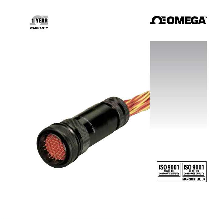
Multi-Pin Thermocouple Connectors
Page 2

omega.com [email protected]
Servicing North America:
U.S.A. Omega Engineering, Inc.
Headquarters: Toll-Free: 1-800-826-6342 (USA & Canada only)
Customer Service: 1-800-622-2378 (USA & Canada only)
Engineering Service: 1-800-872-9436 (USA & Canada only)
Tel: (203) 359-1660 Fax: (203) 359-7700
e-mail: [email protected]
The information contained in this document is believed to be correct, but OMEGA accepts no liability for any
errors it contains, and reserves the right to alter specifications without notice.
For Other Locations Visit omega.com/worldwide
Page 3

Table of Contents
Section 1 Introduction 1
1.1 General Description 1
1.2 Features 1
Section 2 Unpacking 2
Section 3 Operation 2
3.1 Multi-Pin Connector Bodies 2
3.2 Thermocouple Contacts 4
3.3 Backshell Clamps 8
3.4 Installing the Thermocouple Contacts 8
3.4.1 Contact Termination 8
3.4.2 Contact Insertion into the Connector 10
3.4.3 Contact Removal 12
Page
i
Page 4

SECTION 1 INTRODUCTION
1.1 General Description
The OMEGATM Multi-Pin Thermocouple Connectors provide a sturdy
and efficient means of joining multi-wire thermocouple cables.
They can be used with OMEGA
rapid, convenient connection and dismantling of apparatus without
handling individual sensors.
The design utilizes a combination of resilient and rigid dielectric
insulators to eliminate internal air voids and prevent the passage
of air and moisture into or through the connector. Connectors can
withstand ambient temperatures up to 392°F (200°C) contributing to
an extended connector life.
The OMEGA Multi-Pin Thermocouple Connectors do not carry
a MIL spec. number; however, they do meet the performance
requirements of MIL-C 26500E and are intermateable with MIL-C
26500 connectors.
1.2 Features
• Thermocouple alloy pins and sockets
• Air and moisture resistant connection
• Rated to 392°F (200°C)
• Removable crimp contacts
• Accepts 20-24 gage wire
• Aluminum shells
• Black anodized finish
• Threaded coupling
1
TM
Multipair Extension Cable for
Page 5
SECTION 2 UNPACKING
Remove the Packing List and verify that all equipment has been
received. If there are any questions about the shipment, please call
OMEGA
Upon receipt of shipment, inspect the container and equipment for
any signs of damage. Take particular note of any evidence of rough
handling in transit. Immediately report any damage to the shipping
agent.
TM
Customer Service Department.
The carrier will not honor any claims unless all ship ing
material is saved far their examination. After examining
and removing contents, save packing material and carton in
the event reshipment is necessary
SECTION 3 OPERATION
3.1 Multi-Pin Connector Bodies
The contact cavities in the connectors are identified with a spiral
guide line indicating cavity sequence (see Figure 3-1). The first and
last cavities are numbered and every tenth cavity is bracketed. The
number of available cavities are 5, 12, 24, 41, and 55.
NOTE:
2
Page 6
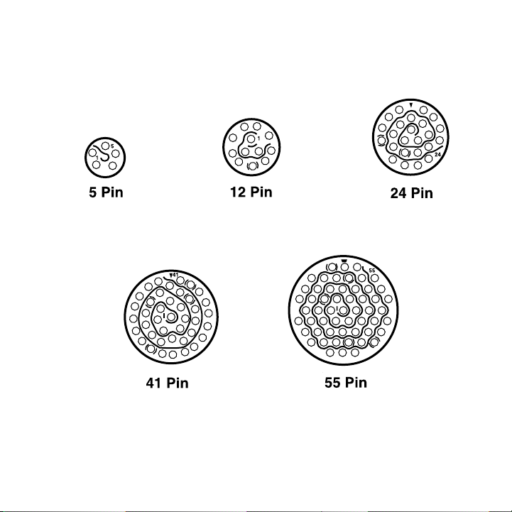
Figure 3-1. Cavity Sequence
3
Page 7

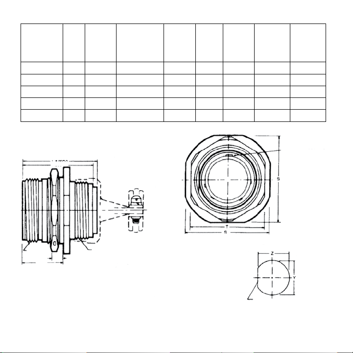
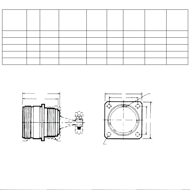
The multi-pin connector bodies come in three styles (plus backshell
cable clamps), MC-male cord, FC-female cord, and FF-female
flanged.
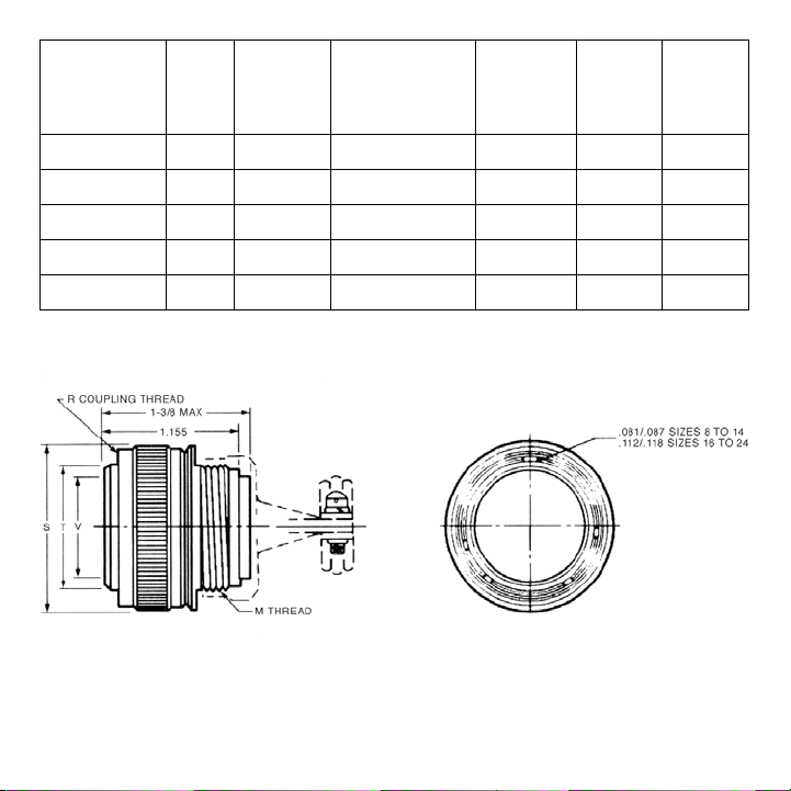
A. MC-Male Cord (see Figure 3-2)
In-line cord connectors with threaded couplings. MC style uses
thermocouple alloy pins.
B. Style FC-Female Cord (see Figure 3-3)
In-line cord connectors with threaded couplings. FC style uses
thermocouple alloy sockets.
C. Style FF-Female Flanged (see Figure 3-4)
Rugged flanged body for bulkhead and chassis mounting. It is
a flange mounted receptacle with threaded coupling. FF style
uses thermocouple alloy sockets.
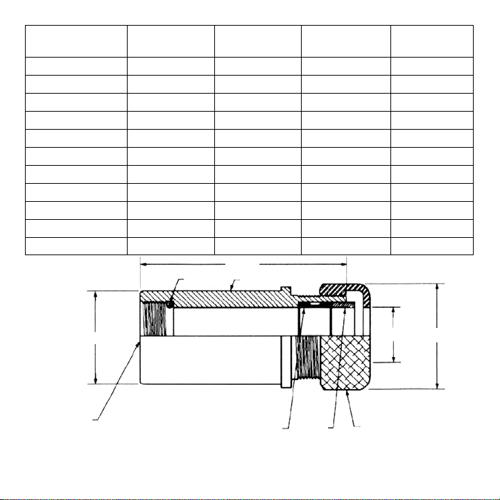
D. Backshell Cable Clamp
Backshell cable clamps provide effective support for the cable
at the male or female connector and prevent twisting and
pulling.
3.2 Thermocouple Contacts
The thermocouple contacts must be installed into the multi-pin
connector bodies by the user. Styles FC and FF use the thermocouple
alloy sockets; Style MC uses the thermocouple alloy pins. Pins and
sockets must be matched to thermocouple alloys.
The push-in crimp style contacts are machined from thermocouple
alloy materials and color coded for easy identification. Gold plated
copper (uncompensated) pins and sockets are available for use
4
Page 8
“M” “S” “T” “V”
Number Backshell Coupling Shell Shell
Connector Shell of Clamp Nut Skirt Internal
Body Size Cavities Thread Dia. Dia. Dia.
MTC-5-MC 10 5
MTC-12-MC 12 12
MTC-24-MC 16 24
MTC-41-MC 20 41 1
MTC-55-MC 22 55 1
9
⁄16-24 UNEF 0.906 0.526 0.444
3
⁄4-20 UNEF 1.078 0.696 0.614
15
⁄16-20 UNEF 1.266 0.892 0.810
3
⁄16-18 UNEF 1.510 1.123 1.041
5
⁄16-18 UNEF 1.625 1.248 1.166
Figure 3-2. MC Style Connector
5
Page 9
Number
Connector
Body
Shell
Size
of
Cavities
MTC-5-FC 10 5
MTC-12-FC 12 12
MTC-24-FC 16 24
MTC-41-FC 20 41 1
MTC-55-FC 22 55 1
1-3/8 MAX.
1.285
“M”
Backshell
Clamp
Thread
9
⁄16-24 UNEF11⁄16-24 1.104
3
⁄4-20 UNEF7⁄8-24 1.291 11⁄8 0.947 0.917
15
⁄16-20 UNEF 11⁄16-18 1.516 15⁄16 1.135 1.105
3
⁄16-18 UNEF 15⁄16-18 1.860 19⁄16 1.385 1.350
5
⁄16-18 UNEF 17⁄16-18 1.954 111⁄16 1.510 1.475
“R”
Coupling
Thread
“S”
Flange
Width
“T”
Locknut
Flats
15
“Y”
Mounting
Hole Dia.
⁄16 0.760 0.730
.081/.087 SIZES 8 TO 14
.122/.128 SIZES 16 TO 24
Mounting
Hole Flat
“Z”
R THREAD M THREAD
.771
0.125 MAX. PANEL THICKNESS
Figure 3-3. FC Style Connector
6
Page 10
R THREA
Number
Connector
Body
Shell
Size
of
Cavities
MTC-5-FC 10 5
MTC-12-FC 12 12
MTC-24-FC 16 24
MTC-41-FC 20 41 1
MTC-55-FF 22 55 1
“M”
Backshell
Clamp
Thread
9
⁄16-24 UNEF11⁄16-24 .937 0.719 0.748 0.572
3
⁄4-20 UNEF7⁄8-24 1.031 0.812 0.913 0.760
15
⁄16-20 UNEF 11⁄16-18 1.250 0.969 1.107 0.948
3
⁄16-18 UNEF 15⁄16-18 1.437 1.156 1.325 1.197
5
⁄16-18 UNEF 17⁄16 1.562 1.250 1.452 1.322
“R”
Coupling
Thread
“S”
Flange
Width
“T”
Mounting
Hole
Centers
“Y”
Back
Mounting
Hole
“Z”
Front
Mounting
Hole
1-3/8 MAX. S
1.155
DM THREAD
Figure 3-4. FF Style Connector
7
T
.125/.116 SIZES 8 to 22
.154/.145 SIZES 24 TO 28
T
(4) HOLES
.091/.097 SIZES 8 to 14
.122/.128 SIZES 16 TO 24
S
Page 11

3.3 Backshell Clamps
(See Figure 3-5, Page 9).
3.4 Installing The Thermocouple Contacts
3.4.1 Contact Termination
Contacts are crimp terminated onto the wire outside the connector
assembly. A specially designed MS standard crimping tool
(OMEGA
pins or sockets.
1. Strip the wire (20 to 24 gage) .170’’ to .201’’; avoid nicking the
2. Insert the stripped wire into the contact pocket until it is visible
3. Fully seat contact in crimp tool positioner.
4. Crimp in one full stroke. (Ratchet action ensures a complete crimp
5. Inspect crimp for wire visibility through inspection hole.
TM
MTC-CT) must be used to properly crimp wires to the
wires or damaging the insulation as it is a functional part of the
sealing system.
through the inspection hole (see Figure 3-6).
every time.)
8
Page 12
Backshelf Max Max
Clamp Dia. B Length Dia. D Dia. E
MTC-5-SHL
MTC-12-SHL 1 2 11⁄8
MTC-24-SHL 11⁄8 21⁄2 11⁄2
MTC-41-SHL 13⁄8 21⁄2 11⁄2
MTC-55-SHL 11⁄2 3 15⁄8
3
⁄4 2 1 3⁄8
1
⁄2
5
⁄8
5
⁄8
7
⁄8
MTC-5-SHL-A
MTC-12-SHL-A 1 2
3
⁄4 2 3⁄4
7
⁄8
MTC-24-SHL-A 11⁄8 21⁄2 1 5⁄16
MTC-41-SHL-A 13⁄8 21⁄2 11⁄8
MTC-55-SHL-A 11⁄2 3 11⁄8
LENGTH
BODYO-RING
DIA. "B"
M THREAD
PER FIGURE 3-2, 3-3, 3-4
SILICONE SEAL CLAMPCAP
DIA. "E" DIA. "D"
Figure 3-5. Backshell Clamps
9
1
⁄8
3
⁄16
7
⁄16
1
⁄2
Page 13
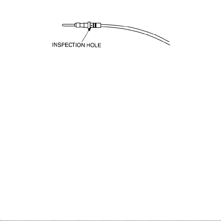
Figure 3-6. Inserting the Stripped Wire into the Contact
3.4.2 Contact Insertion into the Connector
Once the contacts are property crimped onto the wire, they are
inserted into the appropriate cavity of the connector by means of an
insertion tool (OMEGA’s MTC-IT). Assembly of the contacts into the
connector must be made with reasonable care to avoid damage to the
insulation.
1. Lubricate the wire cavities in the back face of insert (on the
connectors) with a very thin film of silicone oil, or equal, before
inserting contacts.
2. Locate contact in insertion tool as shown in Figure 3-7.
3. Align contact with the hole in the rear face of the insert (see Figure
3-8). The alignment of the insertion tool with contact must be
coaxial with the axis of the connector. When the contact has
entered the rear seal portion of the insert, maintain alignment
of contact and tool parallel to and in line with the hole. Insert
the contact to full depth. User will hear contact click-in when
seated fully in retention collet.
10
Page 14
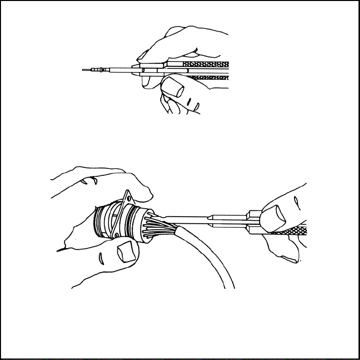
Figure 3-7. Locating Contact into Insertion Tool
Figure 3-8. Aligning Contact
11
Page 15

3.4.3 Contact Removal
A contact is removed from the connector insert with the extraction
tool (OMEGA’s MTC-RT).
1. Set the space sleeve in the proper position for removal of male
or female contact.
2. Place tool over the contact and insert into the cavity (see Figure
3-9). The alignment of the removal tool with the contact must
be coaxial with the axis of the connector.
3. Exert pressure axially to release retention collet. Spacer sleeve
will shoulder at face of insulation when tool is inserted to
proper depth.
4. Push extraction plunger to force the contact out of the rear of
the insert.
5. Grasp contact or wire at the rear of the insert and pull to
complete extraction.
6. Remove tool axially.
7. After using extraction tool the space sleeve should be set
forward in last notch to protect the end of the plunger guide.
12
Page 16
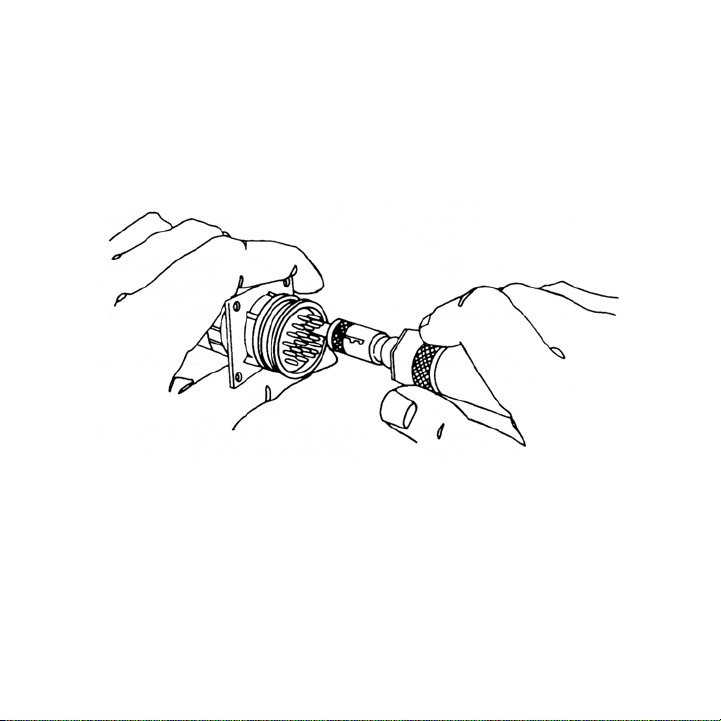
Figure 3-9. Alignment of Removal Tool
13
Page 17

Notes
1 . MS standard assembly tools are required to properly crimp
and assemble connectors.
2. Match pins and sockets to thermocouple alloys.
Example: A 12 cavity connector carries 6 thermocouple circuits
(pairs) requiring 6 positive alloy pins or sockets, and 6 negative
alloy pins or sockets per connector.
3. Order connectors in mating pairs. Style MC mates with Style
FF.
Style MC mates with Style FC.
4. Backshell cable clamps are recommended with each cord
style connector.
14
Page 18

Notes
15
Page 19

WARRANTY/DISCLAIMER
OMEGA ENGINEERING, INC. warrants this unit to be free of defects in materials and workmanship for a period
of 13 months from date of purchase. OMEGA’s WARRANTY adds an additional one (1) month grace period to
the normal one (1) year product warranty to cover handling and shipping time. This ensures that OMEGA’s
customers receive maximum coverage on each product.
If the unit malfunctions, it must be returned to the factory for evaluation. OMEGA’s Customer Service
Department will issue an Authorized Return (AR) number immediately upon phone or written request.
Upon examination by OMEGA, if the unit is found to be defective, it will be repaired or replaced at no
charge. OMEGA’s WARRANTY does not apply to defects resulting from any action of the purchaser,
including but not limited to mishandling, improper interfacing, operation outside of design limits,
improper repair, or unauthorized modification. This WARRANTY is VOID if the unit shows evidence of
having been tampered with or shows evidence of having been damaged as a result of excessive corrosion;
or current, heat, moisture or vibration; improper specification; misapplication; misuse or other operating
conditions outside of OMEGA’s control. Components in which wear is not warranted, include but are not
limited to contact points, fuses, and triacs.
OMEGA is pleased to offer suggestions on the use of its various products. However,
OMEGA neither assumes responsibility for any omissions or errors nor assumes liability for
any damages that result from the use of its products in accordance with information provided
by OMEGA, either verbal or written. OMEGA warrants only that the parts manufactured by the
company will be as specified and free of defects. OMEGA MAKES NO OTHER WARRANTIES OR
REPRESENTATIONS OF ANY KIND WHATSOEVER, EXPRESSED OR IMPLIED, EXCEPT THAT OF
TITLE, AND ALL IMPLIED WARRANTIES INCLUDING ANY WARRANTY OF MERCHANTABILITY
AND FITNESS FOR A PARTICULAR PURPOSE ARE HEREBY DISCLAIMED. LIMITATION OF
LIABILITY: The remedies of purchaser set forth herein are exclusive, and the total liability of
OMEGA with respect to this order, whether based on contract, warranty, negligence,
indemnification, strict liability or otherwise, shall not exceed the purchase price of the
component upon which liability is based. In no event shall OMEGA be liable for
consequential, incidental or special damages.
CONDITIONS: Equipment sold by OMEGA is not intended to be used, nor shall it be used: (1) as a “Basic Component” under 10 CFR 21
(NRC), used in or with any nuclear installation or activity; or (2) in medical applications or used on humans. Should any Product(s) be
used in or with any nuclear installation or activity, medical application, used on humans, or misused in any way, OMEGA assumes no
responsibility as set forth in our basic WARRANTY/DISCLAIMER language, and, additionally, purchaser will indemnify OMEGA and hold
OMEGA harmless from any liability or damage whatsoever arising out of the use of the Product(s) in such a manner.
Direct all warranty and repair requests/inquiries to the OMEGA Customer Service Department. BEFORE
RETURNING ANY PRODUCT(S) TO OMEGA, PURCHASER MUST OBTAIN AN AUTHORIZED RETURN (AR)
NUMBER FROM OMEGA’S CUSTOMER SERVICE DEPARTMENT (IN ORDER TO AVOID PROCESSING
DELAYS). The assigned AR number should then be marked on the outside of the return package and on any
correspondence.
The purchaser is responsible for shipping charges, freight, insurance and proper packaging to prevent breakage in transit.
FOR WARRANTY RETURNS, please have the
following information available BEFORE
contacting OMEGA:
1. Purchase Order number under which the
product was PURCHASED,
2. Model and serial number of the product under
warranty, and
3. Repair instructions and/or specific problems
relative to the product.
OMEGA’s policy is to make running changes, not model changes, whenever an improvement is possible. This affords our customers the
latest in technology and engineering.
OMEGA is a trademark of OMEGA ENGINEERING, INC.
© Copyright 2018 OMEGA ENGINEERING, INC. All rights reserved. This document may not be copied, photocopied, reproduced, translated, or
reduced to any electronic medium or machine-readable form, in whole or in part, without the prior written consent of OMEGA ENGINEERING, INC.
RETURN REQUESTS/INQUIRIES
FOR NON-WARRANTY REPAIRS,
for current repair charges. Have the following
information available BEFORE contacting OMEGA:
1. Purchase Order number to cover the COST
of the repair,
2. Model and serial number of the product, and
3. Repair instructions and/or specific problems
relative to the product.
consult OMEGA
Page 20

Where Do I Find Everything I Need for
Process Measurement and Control?
OMEGA…Of Course!
Shop online at omega.com
TEMPERATURE
MU
Thermocouple, RTD & Thermistor Probes, Connectors,
Panels & Assemblies
MU
Wire: Thermocouple, RTD & Thermistor
MU
Calibrators & Ice Point References
MU
Recorders, Controllers & Process Monitors
MU
Infrared Pyrometers
PRESSURE, STRAIN AND FORCE
MU
Transducers & Strain Gages
MU
Load Cells & Pressure Gages
MU
Displacement Transducers
MU
Instrumentation & Accessories
FLOW/LEVEL
MU
Rotameters, Gas Mass Flowmeters & Flow Computers
MU
Air Velocity Indicators
MU
Turbine/Paddlewheel Systems
MU
Totalizers & Batch Controllers
pH/CONDUCTIVITY
MU
pH Electrodes, Testers & Accessories
MU
Benchtop/Laboratory Meters
MU
Controllers, Calibrators, Simulators & Pumps
MU
Industrial pH & Conductivity Equipment
DATA ACQUISITION
MU
Communications-Based Acquisition Systems
MU
Data Logging Systems
MU
Wireless Sensors, Transmitters, & Receivers
MU
Signal Conditioners
MU
Data Acquisition Software
HEATERS
MU
Heating Cable
MU
Cartridge & Strip Heaters
MU
Immersion & Band Heaters
MU
Flexible Heaters
MU
Laboratory Heaters
ENVIRONMENTAL
MONITORING AND CONTROL
MU
Metering & Control Instrumentation
MU
Refractometers
MU
Pumps & Tubing
MU
Air, Soil & Water Monitors
MU
Industrial Water & Wastewater Treatment
MU
pH, Conductivity & Dissolved Oxygen Instruments
M0192/0718
 Loading...