

Page 1
Series MSX
1-1/16 [26.92]
[64.96]
[92.08]
Magnesense® Differential Pressure Transmitter
• Read LCD values easier with rotatable 180 °
display
• Quick and easy wiring via the optional toolless
terminal block
• Add safety to variety of applications with UL94 V-0
and plenum ratings
Description
The Series MSX Magnesense® Differential Pressure
Transmitter combines the stability and versatility of the
original Series MS2 Magnesense® II transmitter for use in
building control applications. The MSX simplies the ordering
process to deliver the desired conguration, which reduces
product setup time. Pressure ranges are available in Pa,
mm w.c., and in w.c. All pressure ranges can be congured
in unidirectional or bidirectional modes, providing a total
of 32 ranges. The MSX transmitter can provide a linear
pressure output or a linear velocity output with the square
root extraction from the transmitter. Additional parameters
have been included to expand the square root capability to
calculate ow. Dual voltage and milliamp output signals can
be used to provide both control and equipment output signal
verication.
MSX with optional LCD
Applications
• Filter monitoring in air handler units
• Building pressure in pharmaceutical/semiconductor
clean rooms
• Duct static pressure in commercial buildings
• Air velocity/ow in VAV systems
Specications
Service: Air and non-combustible, compatible gases.
Wetted Materials: Consult factory.
Accuracy: ±1 % FSO.
Stability: ±1 % FSO/year.
Temperature Limits: -20 °C to 70 °C (-4 °F to 158 °F).
Pressure Limits: Ranges 0 and 1: 3.6 psi max operation, 6 psi
burst; Ranges 2, 3 and 4: 6 psi max operation, 6 psi burst.
Power Requirements: 10 VDC to 36 VDC (2-wire), 17 VDC to
36 VDC or isolated 21.6 VAC to 33 VAC (3-wire).
Output Signals: 4 mA to 20 mA (2-wire); 0 V to 10 V or 0 V to 5
V selectable (3-wire).
Response Time: Instantaneous (default) or 3 s (selectable).
Zero and Span Adjustments: Digital push-button.
Loop Resistance: Current output: 0 Ω to1250 Ω max; Voltage
output: min. load resistance 1 kΩ.
Current Consumption: 21 mA max continuous.
Electrical Connections: 4-wire removable European style
terminal block for 16 AWG to 26 AWG.
Electrical Entry: 1/2 in NPS thread.
Display (optional): 4 digit LCD.
Process Connections: 1/8 in, 3/16 in, 1/4 in, 5 mm, and 6 mm
ID exible tubing.
Enclosure Rating: NEMA 4X (IP66); UL 2043 (Plenum); UL94
V-0.
MSX Square Housing with
optional LCD
Mounting Orientation: Pressure sensor measurement
unaffected by orientation.
Weight: 230 g (8.0 oz).
Compliance: CE.
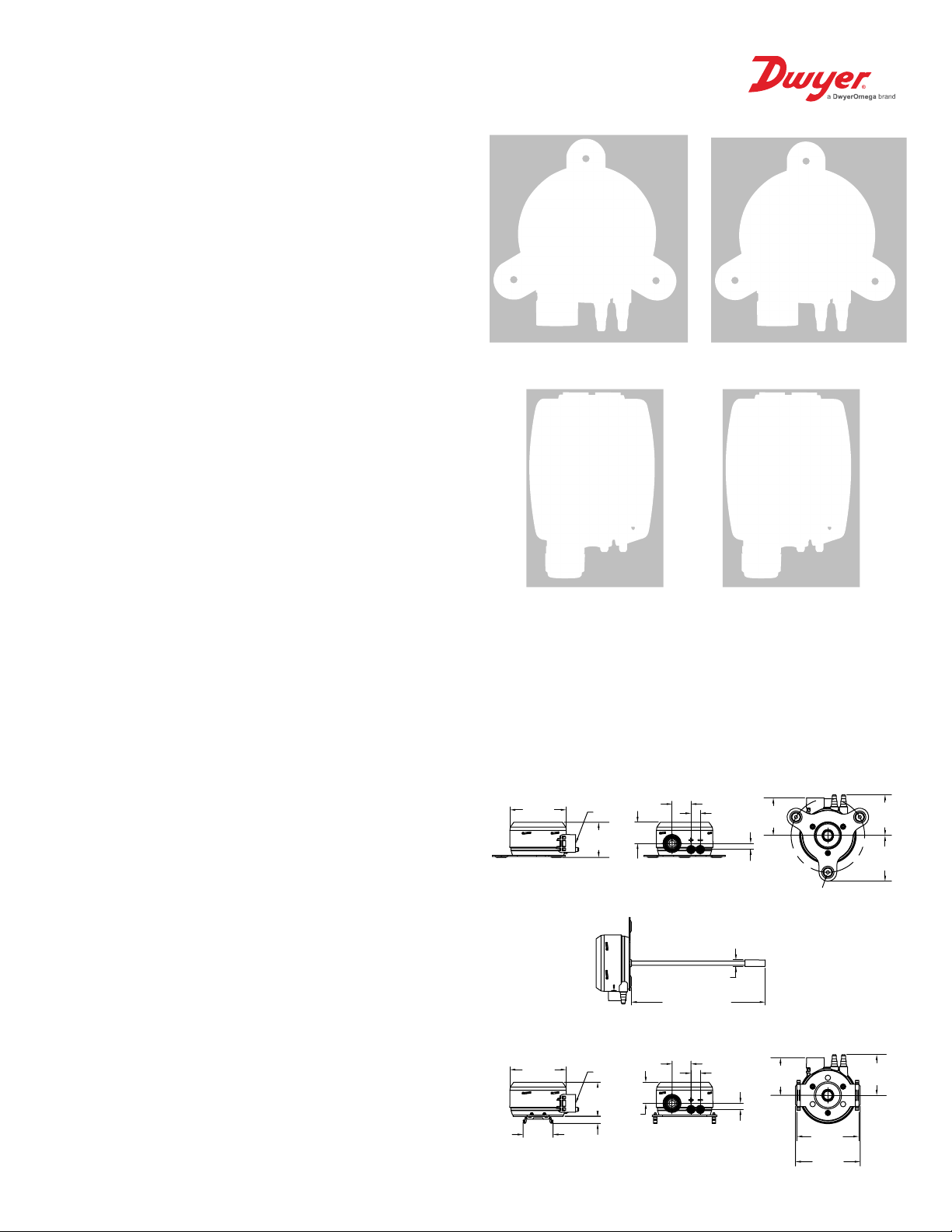
Dimensions - Round Housing
3-9/64
[79.96]
3-9/64
[79.96]
1-43/64
[42.50]
1/2 NPSM
1-31/32
[49.89]
1/2 NPSM
1-29/32
[48.36]
13/32
[10.29]
1-3/16 [30.02]
Wall mount bracket
7-31/64 [190.12]
Duct mount bracket
1-1/16 [26.92]
1-3/16
[30.02]
DIN mount bracket
33/64
[13.08]
3/8 [9.53]
33/64 [13.08]
2-3/32
[53.34]
11/32 [8.56]
[3] 3/16 [4.57] HOLES
EQUALLY SPACED ON A
4-7/64 [104.53] BC
2-3/32
[53.34]
11/32
[8.56]
3-15/32
[88.19]
3-5/8
2-9/32
[57.79]
2-9/16
2-9/32
[57.79]
Page 2
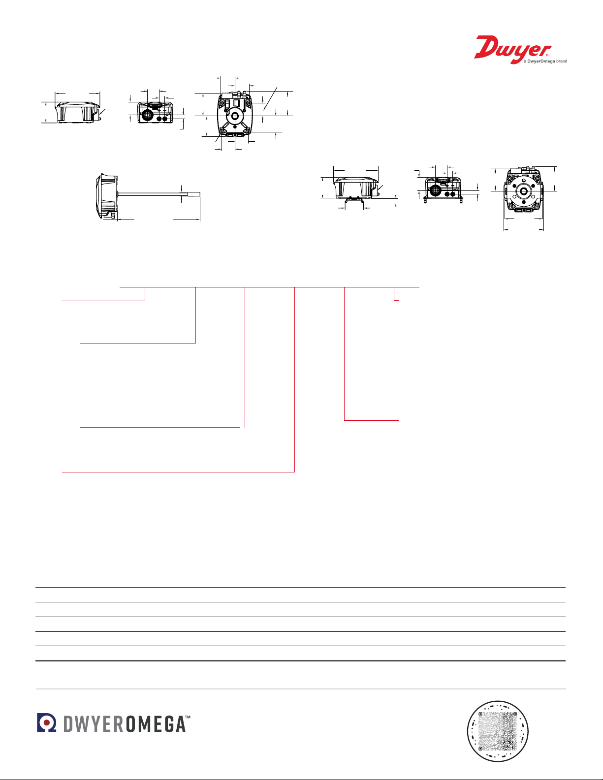
Dimensions - Square Housing
1-29/32
[48.43]
[57.79]
1-19/64 [33.02]
1/2
NPSM
1-29/32
[48.43]
4-3/32
[103.98]
1-1/16 [26.92]
33/64
[13.08]
1-3/16
[30.34]
11/32 [8.56]
2-3/32
[53.34]
2-9/32
[57.79]
1-57/64
[48.10]
1-11/64
[29.92]
1-29/64
[36.75]
1-19/64 [33.02]
1-19/64
[33.02]
1-13/64
[30.48]
1-13/64
[30.48]
[4] 13/64 [5.08] HOLES
3/8 [9.53]
7-9/16 [191.90]
3-5/8 [92.08]
Dimensions are in inches and [mm] millimeters are in brackets.
1-11/64
1-19/64
4-3/32
[103.98]
1-1/16 [26.92]
1/2
NPSM
1-3/16
[30.34]
Wall mount bracket
7-9/16 [191.90]
33/64
2-3/32
[13.08]
[53.34]
11/32 [8.56]
[4] 13/64 [5.08] HOLES
3/8 [9.53]
1-57/64
[48.10]
1-13/64
[30.48]
Duct mount bracket DIN mount bracket
[33.02]
1-13/64
[30.48]
[29.92]
1-29/64
[36.75]
2-9/32
How to Order
MSX -W 1 3 -IN -LCD
1-29/32
[48.43]
4-3/32
[103.98]
1-43/64 [42.50]
1-3/16
[30.34]
1/2
NPSM
27/64 [10.84]
1-1/16 [26.92]
33/64
[13.08]
11/32 [8.56]
2-3/32
[53.34]
3-15/32
[88.19]
2-9/32
[57.79]
SERIES
MSX: Magnesense
®
differential pressure
transmitter
MOUNTING
-W: Wall mount
-U: Universal (wall or duct) mount
-N: DIN rail mount
-S: Square Housing Wall mount
-Y: Square Housing Universal (wall or duct) mount
-Z: Square Housing DIN rail mount
DIRECTION
1: Unidirectional
2: Bidirectional
RANGE
0: .5 in w.c., 125 Pa, 12.5 mm w.c.
1: 1 in w.c., 250 Pa, 25 mm w.c.
2: 5 in w.c., 1250 Pa, 125 mm w.c.
3: 28 in w.c., 7000 Pa, 700 mm w.c.
4: 15 in w.c., 4000 Pa, 400 mm w.c.
Accessories
Model Number Description
A-155 Cable gland with 12.7 mm (1/2 in) male NPT tting
A-480 Plastic static pressure tip
A-481 Installer kit, includes 2 plastic static pressure tips and 2.1 m (7 ft) of PVC tubing
A-MSX-LCD Replacement display for the Series MSX
A-MSX-ORING Replacement O-ring for the Series MSX
OPTIONS
-A481: Installer kit
-COM: BACnet/Modbus
®
communications
-FC: Factory calibration certicate
-FP: Filtered pickup with barb
-GLD: Liquid tight cable gland tting
-LCD: Liquid crystal display
-NIST: NIST traceable calibration
certicate
-STX: Two (2) plastic static pressure tips
-TT: Toolless terminal block
PRESSURE UNIT
-IN: Inches water column
-PA: Pascal
-MM: Millimeters water column
Improving the world, one measurement at a time.
DS-MSX Rev. 8
TM
 Loading...