

Page 1
USER’S GUIDE
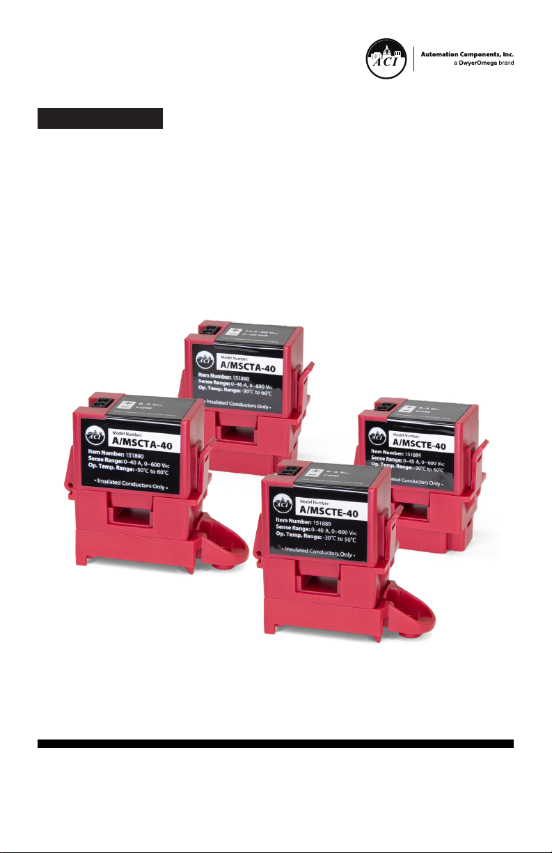
MSCTA-40 & MSCTE-40 Series
Analog Output Current Sensor
workaci.com
For latest product manuals:
workaci.com/resources/resource-library
Page 2

CONTACT
Automation Components, Inc.
workaci.com/contact-us
Telephone:
1-(888) 967-5224
Fax:
(608) 831-7407
The information contained in this document is believed to be
correct, but ACI accepts no liability for any errors it contains,
and reserves the right to alter specifications without notice.
Page 3

Table of Contents
1. Precautions ................................................................................................4
2. General Information .................................................................................... 4
3. Installation Instructions ..........................................................................5
4. Wiring Instructions .................................................................................7
5. Troubleshooting ........................................................................................8
6. Specifications ...........................................................................................9
3Table of Contents
Page 4
1. Precautions
• This product is not intended to be used for Life or Safety
applications.
• This product is not intended for use in any hazardous or classied
locations.
• The MSCTA and MSCTE Series Current Sensors must be used on
Insulated Conductors Only!
HIGH VOLTAGE
• Disconnect and lock out all power sources before installation as
severe injury or death may result from electrical shock due to
contact with high voltage wires.
2. General Information
The MSCTA and MSCTE Analog
Current Sensors are designed for
use in any AC current monitoring
application in which you are
looking to monitor a particular
piece of equipment. Applications
may include monitoring a
resistive type load such as an
incandescent light bulb, heating
element as well as any single
speed linear load.
The MSCTA-40 is a 2 wire
4-20mA loop current sensor
which requires a +13.5 to 30VDC
power supply. The MSCTE-40
has a 0-5VDC output, and does
not require external power, since
the power for the current sensor
is induced from the conductor
being monitored.
The split-core current sensors
work great in retrot applications
and for use on service
technicians vehicles since one
or two parts will work in most
applications and can be easily installed without disconnecting any
wires.
The MSCTA/E series sensors can be secured to the monitored cable
using a cable tie and the integrated cable tie anchor feature of the
housing. The sensors also come with an at tachable mounting foot
that allows the unit to be mounted in any position using one Tek
screw or snapped directly on a 35mm DIN rail.
4 MSCT Series
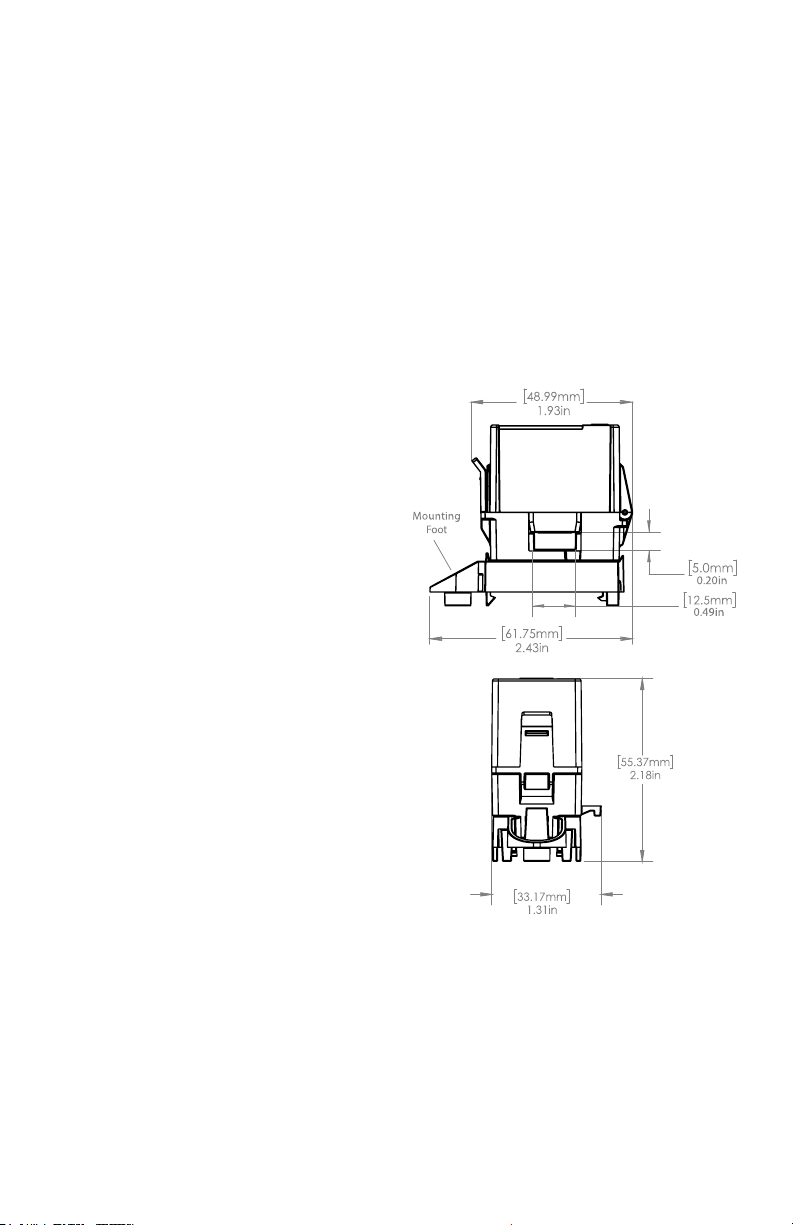
Figure 1: Enclosure Dimensions
Page 5
3. Installation Instructions
Make sure that all installations are in
compliance with all national and
local electrical codes. Only qualied
individuals that are familiar with
codes, standards, and proper safety
procedures for high-voltage
installations should attempt
installation. The MSCTA-40 is a 2
wire 4-20mA loop current sensor
which requires a +13.5 to 30 VDC
power supply. The MSCTE-40 has a
0-5VDC output, and does not require
external power, since the power for
the current sensor is induced from
the conductor being monitored. The
MSCT sensor has multiple mounting
options. The MSCT sensor enclosure
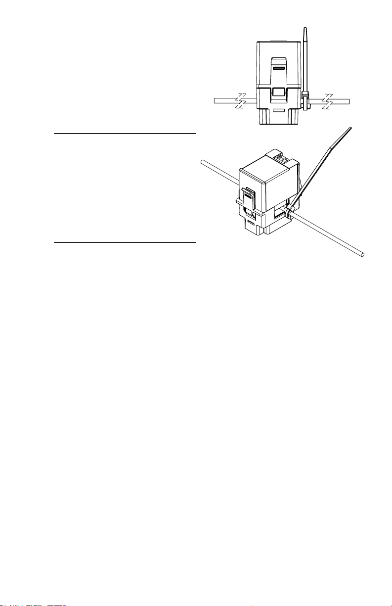
has a plastic feature that allows for the monitored current wire to be
cable tied to the enclosure for free hanging installation applications
- See Figure 4 (pg. 6). This will be the preferred method for most
installations.
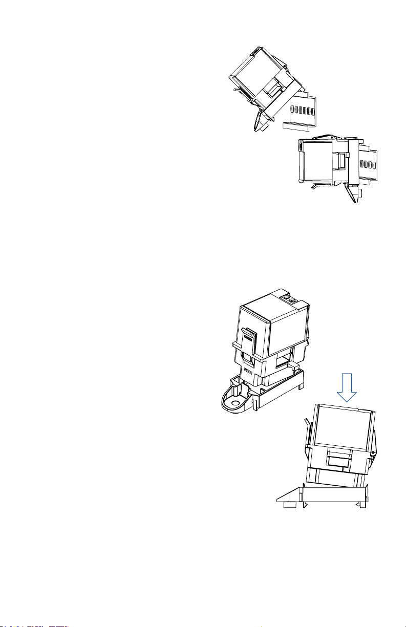
Alternatively, the current sensor
product comes with a detached
mounting foot. With the mounting
foot attached to the sensor main
body, the enclosure may be
mounted in any position using the
one #8 x 3/4” Tek screw through
the hole in the mounting foot. The
mounting clip must be snapped
into position- See Figure 3. Align
the front of the MSCT Sensor (latch)
with the front of the mounting clip
(screw mount). Insert the MSCT
Sensor unit at a slight angle, with
the back of the unit leading down,
and push down to snap into place.
Additionally, the enclosure may
be snapped directly on a 35mm
DIN rail - See Figure 2. Leave a
minimum distance of 1” (3 cm)
between the current switch and any
other magnetic devices such as
contactors and transformers.
Figure 2: DIN Rail Installation
Figure 3: Mounting Foot Attachment
5Installation Instructions
Page 6
LATC H OPER ATION
Press down on the side tab and
swing the top of the unit up to
open the split core current
switch. Press down rmly on the
cover to close the current switch.
An audible “click” will be heard
as the tab slides over the tongue
on the base.
CAUTION
Mating surfaces of the magnetic
core are exposed when the
sensor is open. Operation can
be impaired if anything prevents
good contact between pole
pieces. Visually check the
mating parts of the core before
closing the current sensor.
Figure 4: Wire Mounting
6 MSCT Series
Page 7
4. Wiring Instructions
ACI recommends the use of a two conductor 16 to 22 AWG shielded
cable or twisted pair copper wire only for all analog current sensor
applications. All wiring must comply with all local and National
Electric Codes.
Note
When using a shielded cable, be sure to connect only (1) end of the
shield to ground at the controller. Connecting both ends of the shield
to ground may cause a ground loop.
When removing the shield from the sensor end, make sure to properly
trim the shield to prevent any chance of shorting.
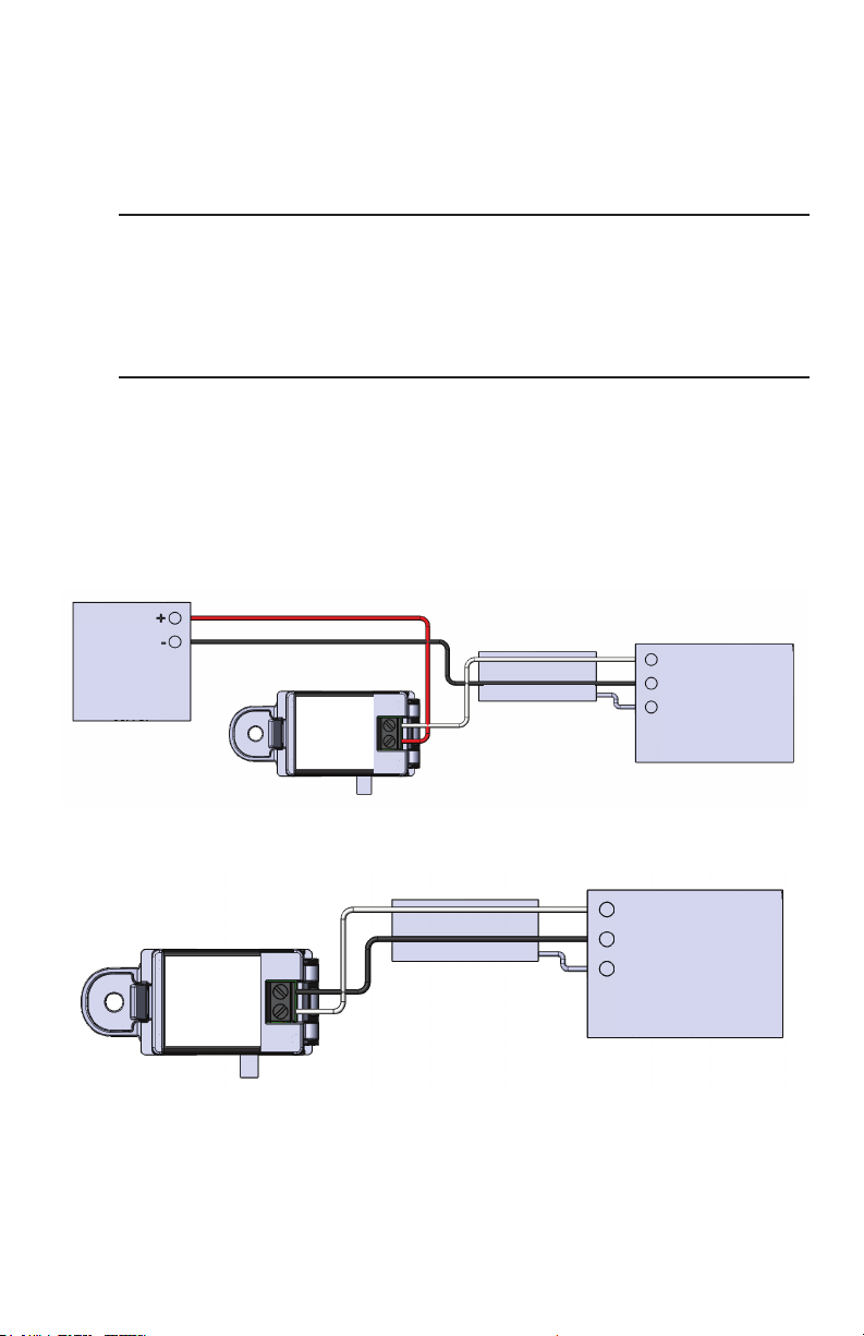
The current sensor terminals are polarity sensitive and represent
a linear 4 to 20 mA (MSCTA-40) or 0 to 5 VDC (MSCTE-40) output
signal. See diagrams below for proper wiring. Tighten the screws at
the terminal block connections to the recommended torque of 0.5 to
0.6 Nm (4.43 to 5.31 in-lbs.). The aperture (hole) size of the current
sensor is 0.20” (5.0 mm) x 0.49” (15.5 mm). It ts 10AWG to 14 AWG
THHN Insulated Wire.
13.5 TO 30 VDC
DC POWER
SUPPLY
COM
0-5VDC
4-20mA
-
13.5-30VDC
+
Figure 5: MSCTA-40 Wiring Diagram
SHIELDED CABLE
-
+
Figure 6: MSCTE-40 Wiring Diagram
SHIELDED CABLE
4 TO 20mA SIGNAL INPUT
UNIVERSAL INPUT
COMMON
GND (SHIELDED)
BAS, PLC, DDC,
AUTOMATION PANEL
UNIVERSAL INPUT
COMMON
GND (SHIELDED)
0 TO 5VDC SIGNAL INPUT
BAS, PLC, DDC,
AUTOMATION PANEL
7Wiring Instructions
Page 8
5. Troubleshooting
Problem Solutions
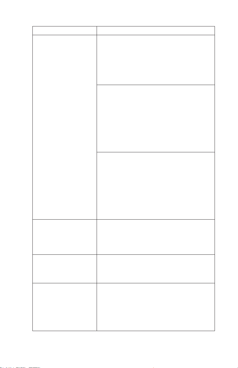
No Reading
Erratic Readings
Inaccurate Readings
Current Sensor
is operating at a
low-level current or
failing to operate
within the accuracy
specications:
• Verify that there is current owing
through the conductor being
monitored with a clamp-on current
probe.
• Check the polarit y of the circuit.
• Verify that the terminals are screwed
down, wires are rmly in place.
MSCTA-40
• Conrm that you have +13.5 to
30VDC in series with the current
sensor output terminals and the
analog input of the control panel.
• Disconnect the input to the control
panel and then insert a current meter
(mA range) in series with the current
sensor output to verify that the circuit
is working properly.
MSCTE-40
• No power supply needed. The power
for the current sensor is induced
from the conductor being monitored.
• Disconnect the wires from the current
sensor output and tighten down the
screws. Measure the voltage across
the current sensor output with a
Voltmeter to verify that the sensor is
working properly.
• Verify that the wires are terminated
properly.
• In areas of high RF interference,
shielded cable may be necessary to
stabilize signal.
If you suspect that the current sensor
is not reading within the accuracy
specications, please contact the factory
for assistance.
• Visually check the mating parts of
the core to ensure there is no debris
between the split contacts.
• Remove all debris or dust manually
and close the current sensor.
• Continue to retest the sensor in your
application.
8 MSCT Series
Page 9

6. Specifications
Monitored Current Type: AC Current
Maximum AC Voltage: 600 VAC
Isolation Voltage: 2200 VAC
Operating Frequency Range: 50/60 Hz
Core Style: Split-Core
Supply Voltage (MSCTA-40): +8.5 to 30 VDC (Reverse Polarity
Protected)
250 Ohm Load (1-5 VDC): +13.5 to 30 VDC
500 Ohm Load (2-10 VDC): +18.5 to 30 VDC
Supply Current (MSCTA-40): 25 mA minimum
Supply Voltage (MSCTE-40): Induced from the Monitored Conductor
(Insulated Conductors only)
Maximum Load Resistance at 24 VDC (MSCTA-40): 775 Ohms
(Formula : [24 VDC - 8.5 VDC] / 0.020 A)
Sensor Amperage Range: 40 A
Output Signal: MSCTA-40: 4 to 20 mA (2-Wire, Loop Powered)
MSCTE-40: 0-5 VDC
Response Time: MSCTA-40: < 600 mS (Rise and Fall Times)
MSCTE-40: < 300 mS (Rise and Fall Times)
Aperture Size (Diameter) | Wire Size: 0.20” (5.0 mm) x 0.49” (12.5 mm)
| Fits 10 AWG to 14 AWG THHN Insulated Wire
DIN Rail Size: 35 mm
Operating Temperature Range1: MSCTA: -22 to 140 ºF (-30 to 60 ºC
MSCTE: -22 to 122 ºF (-30 to 50 ºC)
Operating Humidity Range: 10 to 95 %, non-condensing
Storage Temperature | RH Range: -40 to 158 °F (-40 to 70 °C) | 10 %
to 95 % RH, non-condensing
Enclosure Material | Flammability Rating: PC/ABS (Polycarbonate/ABS
Blend) | UL94-V0
Wiring Connections: 2 Position Screw Terminal Block (Polarity
Sensitive)
Wire Size: 16 to 22 AWG (1.31 mm2 to 0.33 mm2) Copper Wires Only
Terminal Block Torque Rating: 4.43 to 5.31 in-lbs. (0.5 to 0.6 Nm)
Minimum Mounting Distance: 1” (2.6 cm) between current switch &
other magnetic devices (Relays, Contactors, Transformers)
Agency Approvals: UL/CUL US Listed (UL 508) Ind. Control Equipment
(File # E309723), CE, RoHS, UKCA, FCC, CAN ICES-3 / NMB-3
Product Weight: 0.165 lbs. (0.075 Kg)
Product Dimensions (L x W x H): 1.93” (48.99 mm) x 1.31” (33.17 mm)
x 2.18” (55.37 mm)
Note1: Maximum 40 °C for 50 Hz operation of MSCTE
9Specications
Page 10

Accuracy Current
Application
Range
Temperature
Frequency
MSCTA-40
MSCTE-40
±0.75 % FS
(±0.3 A)
±0.75 % FS
(±0.3 A)
±0.4 % FS
(±0.16 A)
±0.75 % FS
(±0.3 A)
±0.75 % FS
(±0.3 A)
Greater
than 2 A
Greater
than 2 A
Full Range
Full Range
Full Range
5 to 140 °F
(-15 to 60 °C)
32 to 140 °F
(0 to 60 °C)
5 to 95 °F
(-15 to 35 °C)
-22 to 122 °F
(-30 to 50 °C)
-22 to 86 °F
(-30 to 30 °C)
60 Hz
50 Hz
60 Hz
60 Hz
50 Hz
10 MSCT Series
Page 11

WARRANTY
The ACI MSCTA and MSCTE Current Sensor Series are covered by ACI’s
Five (5) Year Limited Warranty, which is located in the front of ACI’S
SENSORS & TRANSMITTERS CATALOG or can be found on ACI’s website:
www.workaci.com.
W.E.E.E. DIRECTIVE
At the end of their useful life the packaging and product should be
disposed of via a suitable recycling centre. Do not dispose of with
household waste. Do not burn.
FCC Compliance Statement
This device complies with part 15 of the FCC Rules. Operation is subject
to the following two conditions: (1) This device may not cause harmful
interference, and (2) this device must accept any interference received,
including interference that may cause undesired operation.
Page 12

®
workaci.com
I0000984
Improving the world, one measurement at a time.
TM
UNIVERSAL
FLOW MONITORS
 Loading...