

Page 1
Nozzle Band Heaters
Construction Characteristics
The ideal solution for applications that require high watt
densities (Watt/in
Band heaters are capable of temperatures up to 760°C
(1400°F) and watt densities up to 23.25 Watt/cm
(150 Watt/in2). The recommended maximum watt density for
a specific application will depend on the heater size and its
operating temperature.
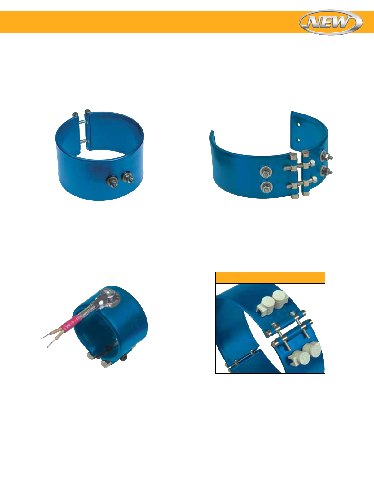
Unbreakable Power Screw Terminals
Only these band heaters offer this unique screw terminal
design. The stainless steel power screw terminals are
resistant to over-torquing.
2
) and/or high operating temperatures.
2
Specially formulated mineral insulated tape providing
excellent thermal conductivity and dielectric strength is
used to insulate the nickel chrome resistance wire from the
stainless steel sheath. The heater assembly is formed under
pressure to a precise diameter with a thin low-mass cross
section, assuring fast heat-up rates and reduced cycle times.
Superior Clamping Mechanism
The clamping brackets are formed from the outer sheath of
the heater, providing a unique one-piece built-in construction
strap. The clamping power is generated through barrel nuts
and socket head screws, which as an integral part of the
built-in strap, provide superior clamping force for maximum
performance and optimal heater life.
Innovative Lead Terminations
Smaller size band heaters are powered-up by means of
lead wire terminations. To insure a resilient connection
that will withstand abrasion, mechanical abuse and keep
contaminants out of the transition area, a specially designed
stainless steel transition cap with a built-in strain relief was
developed. The cap is welded to the sheath and the cavity
is filled with insulating cement, sealing the band heater from
contaminants.
Single Port IglooTM Covers
Unique Igloo Ceramic Covers
To eliminate exposed wiring/screw terminals on band heater
installations, a 90° double port ceramic cap was designed.
This unique and exclusive Igloo ceramic terminal insulator
fits over the entire terminal and lug, leaving no exposed
wiring.
1
Page 2
Specifications & Tolerances
Nozzle Band Heaters
If non-standard widths or tighter tolerances are required,
contact OMEGA.
Performance Ratings
Maximum Temperature: 760°C (1400°F)
Nominal Watt Density:
Nozzle Bands, Under 3" Diameter: 4.7 to 15.5 Watt/cm
(30 to 100 Watt/in2)
Barrel Bands, 3" and Greater in Diameter:
3.1 to 10.9 Watt/cm2 (20 to 70 Watt/in2)
Maximum Watt Density: 23 Watt/cm2 (150 Watt/in2)
dependent on heater size, operating temperature and
termination
Electrical Ratings
Maximum Voltage: 480 Vac per termination
Dual Voltage: Available depending on heater configuration
Maximum Amperage:
Lead Wire Termination: 10A
Screw Terminations: 8-32UNF—20A, 10-32UNF—25A
Resistance Tolerance: +10%, −5%
Wattage Tolerance: +5%, −10%
Diameter/Width Limitations
One-Piece Construction Expandable Construction Two-Piece Construction
Width Inside Diameter Inside Diameter Inside Diameter
in mm in mm in mm in mm
1 25.4 1 to 10 25.4 to 254.0 n/a n/a 3 to 25 76.2 to 635.0
11⁄2 38.1 1 to 14 25.4 to 355.6 21⁄2 to 14 63.5 to 355.6 3 to 25 76.2 to 635.0
2 50.8 11⁄2 to 14 38.1 to 355.6 21⁄2 to 14 63.5 to 355.6 3 to 25 76.2 to 635.0
21⁄2 63.5 11⁄2 to 14 38.1 to 355.6 21⁄2 to 14 63.5 to 355.6 3 to 25 76.2 to 635.0
3 76.2 11⁄2 to 14 38.1 to 355.6 21⁄2 to 14 63.5 to 355.6 3 to 25 76.2 to 635.0
31⁄2 88.9 13⁄4 to 14 44.5 to 355.6 21⁄2 to 14 63.5 to 355.6 3 to 25 76.2 to 635.0
4 101.6 2 to 14 50.8 to 355.6 21⁄2 to 14 63.5 to 355.6 3 to 25 76.2 to 635.0
41⁄2 114.3 21⁄4 to 14 57.2 to 355.6 21⁄2 to 14 63.5 to 355.6 3 to 25 76.2 to 635.0
5 127.0 21⁄2 to 14 63.5 to 355.6 21⁄2 to 14 63.5 to 355.6 3 to 25 76.2 to 635.0
51⁄2 139.7 23⁄4 to 14 69.9 to 355.6 3 to 14 63.5 to 355.6 3 to 25 76.2 to 635.0
6 152.4 3 to 14 76.2 to 355.6 3 to 14 76.2 to 355.6 3 to 25 76.2 to 635.0
61⁄2 165.1 31⁄4 to 14 82.6 to 355.6 31⁄4 to 14 82.6 to 355.6 31⁄4 to 25 82.6 to 635.0
7 177.8 31⁄2 to 14 88.9 to 355.6 31⁄2 to 14 88.9 to 355.6 31⁄2 to 25 88.9 to 635.0
71⁄2 190.5 33⁄4 to 14 95.3 to 355.6 33⁄4 to 14 95.3 to 355.6 33⁄4 to 25 95.3 to 635.0
8 203.2 4 to 14 101.6 to 355.6 4 to 14 101.6 to 355.6 4 to 25 101.6 to 635.0
Physical Size Construction Limitations
Nominal Gap—Built-In Bracket:
Less than 44 mm (13⁄4") Diameter: 6 mm (1⁄4")
44 to 51 mm (13⁄4 to 2") Diameter: 8 mm (5⁄16")
51 to 127 mm (2 to 5") Diameter: 10 mm (3⁄8")
127 mm to 0.46 m (5 to 18") Diameter: 13 mm (1⁄2")
2
Greater than 0.46 m (18") Diameter: 19 mm (3⁄4")
If a larger gap is required for probes or thermocouples,
specify when ordering.
Maximum Inside Diameters:
One-Piece: 355.6 mm (14")*
Expandable: 355.6 mm (14")*
Two-Piece: 635.0 mm (25")
Over 635.0 mm (25") will require multiple segments.
Contact OMEGA.
* Note: OMEGA recommends two-piece construction for heaters 10" ID
and greater.
Standard Widths: 25.4 to 203.2 mm (1 to 8")
Width Tolerance: 2.4 mm (±3⁄32")
Exposed electrical wiring on band heater
installations is a violation of Electrical Safety
Codes including O.S.H.A.
2
Additional Limitations
• For heaters less than 102 mm (4") in diameter, the maximum width is twice the diameter.
• Heaters with standard brackets are available from 25 to 203 mm (1 to 8" wide, while
heaters with low profile brackets are available from 25 to 152 mm (1 to 6") wide.
• 25 mm (1") diameter heaters are only available in 25 to 38 mm (1 and 11⁄2") widths.
• For heaters from 254 mm (10") diameter up to 0.6 m (25") diameter, OMEGA recommends using
2-piece construction for superior clamping. Over 0.6 m (25") diameter, 3 or 4 segments are
recommended.
• Combinations of some minimum and maximum variations may not be available.
Contact OMEGA with your special requirements.
• Post terminals are only available on heaters greater than 64 mm (21⁄2") in diameter and 38 mm
(11⁄2") in width.
Page 3
Nozzle Band Heaters
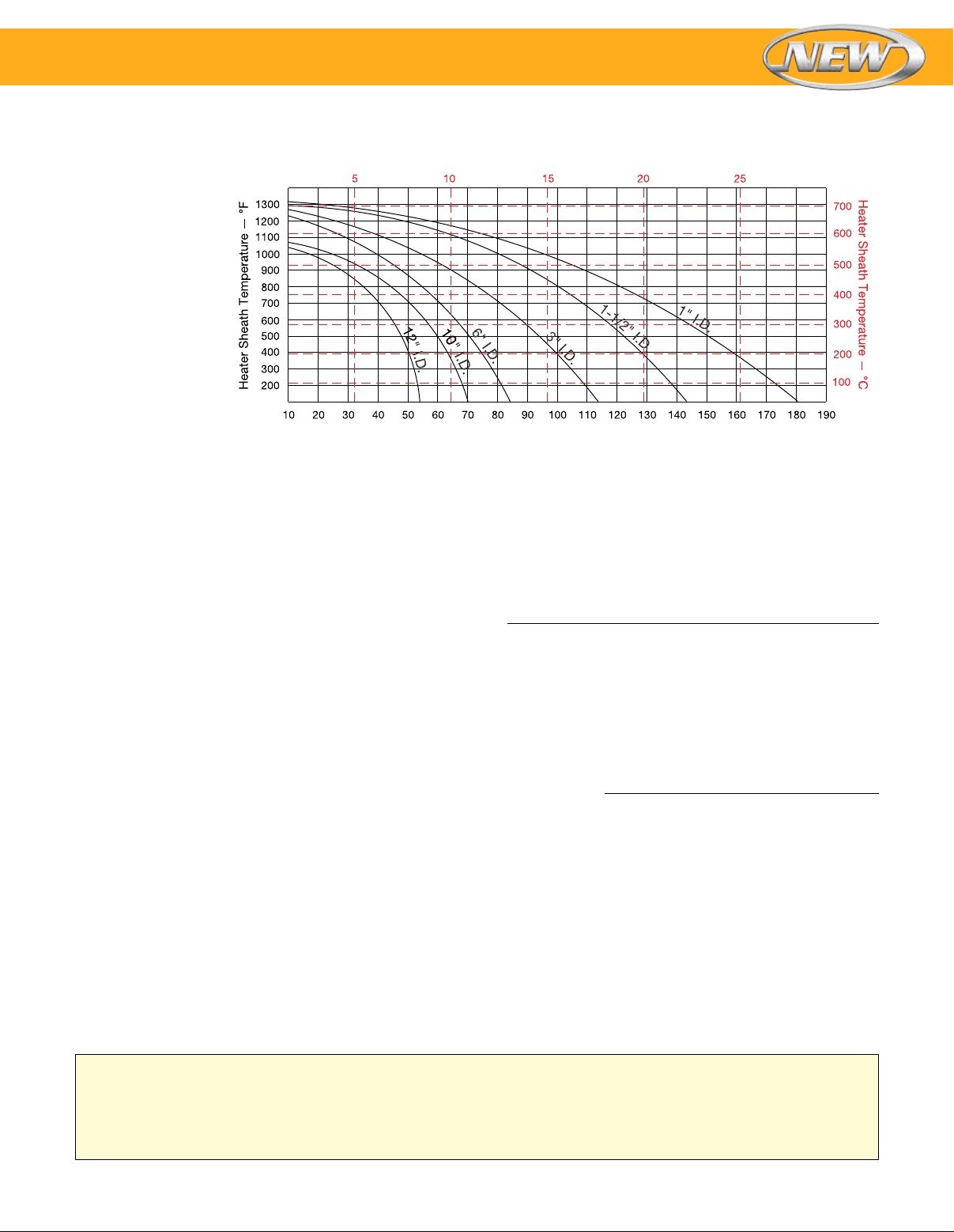
Maximum Watt Densities
Maximum Allowable
Watt Density
The chart displays
the maximum Watt
Density curves for
various diameter
heaters. Use this chart
when determining the
appropriate wattage
value for your chosen
heater.
Be aware that certain
factors will require
you to derate the watt
density (Watt/in2) of
your heater selection.
CAUTION: Failure to adhere to the
maximum allowable watt density per
heater size will result in poor operating life.
Calculating Maximum Watt Density
Watt Density–w/cm2 (dashed lines)
Watt Density–w/in
2
(solid lines)
Factors to be taken into consideration:
A. Type of controls
B. Voltage variations
C. Machine cycling rate
D. Type of resin being processed
E. Coefficient of thermal expansion and conductivity
of the cylinder
F. Designing a heater that closely matches the wattage
requirement will decrease the frequency of cycling and
temperature overshoot, thereby increasing the life of the
heater
Once these factors have been established, proceed with
the following steps:
1. Determine the maximum operating temperature.
2. Calculate the total wattage required to obtain the maximum
operating temperature.
3. Determine the quantity and size of the heater bands to
be used. Due to clamping concerns, 51 through 76 mm
(2" through 3") wide band heaters have long proven to be
the most efficient and reliable in most cylindrical heating
applications.
4. Determine individual band heater wattage by dividing the
total required wattage by the quantity of band heaters
selected.
5. Determine the band heater’s heated area by subtracting
unheated (cold) areas created by screw terminals, gaps,
holes, and cutouts.
Nominal Unheated Areas
Construction Style Cold Area to Subtract
One-piece band 1" × width
One-piece expandable band 11⁄2" × width
Two-piece band 2" × width
For each hole or cutout add to the cold area from the Table
the (Hole size +
to use in the following formula to calculate the heater watt
density.
Watt Density Formula
Watt Density =
(Watt/in2) (3.14×Band ID×Band Width)–(Cold Area)
6. Check in the above graph that the calculated watt density
does not exceed the maximum recommended watt density.
Locate the maximum cylinder temperature required on the
left-hand side of the graph, follow the horizontal line until it
intersects with the line of the band heater being used, and
read directly down to obtain the maximum recommended
watt density (watt/in2).
7. If the calculated watt density is higher than the
recommended value, it must be corrected or it will cause
poor heater life. This can be accomplished by using more
band heaters or lowering the heater wattage.
8. Should you have a problem in selecting the proper band
heater or establishing watt density for your application,
contact OMEGA.
1
⁄2") × heater width. This is total cold area
Wattage
Correction Factors
For heaters wider than 76.2 mm (3"),
reduce maximum allowable watt
density from chart by 20%.
For applications using insulating
shroud, reduce maximum allowable
watt density from chart by 25%.
Do not use insulating blankets if
heater temperatures are above
649°C (1200°F). Failure to adhere
will result in premature heater failure.
3
Page 4
Nozzle Band Heaters
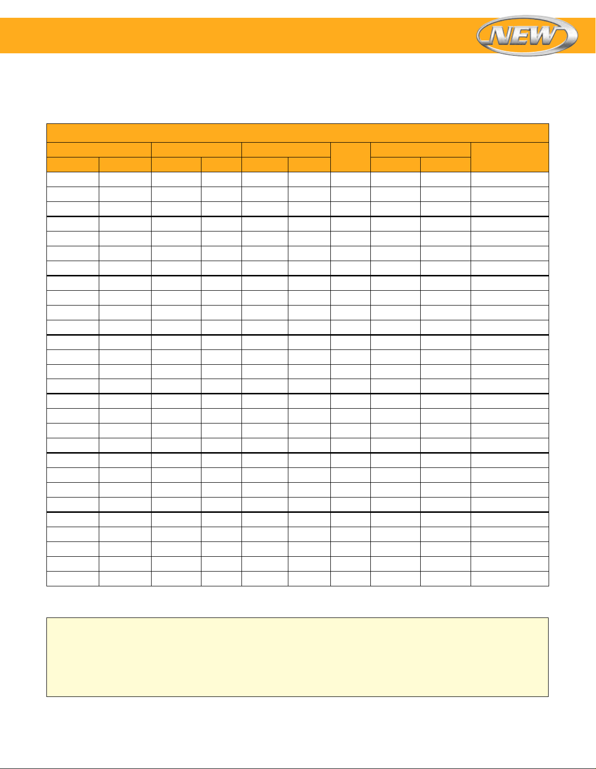
Nozzle Band Heaters Available Through the Terminator Program
Model Numbers listed are for heaters with Type W2 termination—right-angle wire braid leads [305 mm (12") leads,
254 mm (10") stainless steel braid]. Other terminator program terminations and options can also be applied to stock
heaters (see To Order chart below ).
To Order
Model No. Inner Dimension Width
MPP50101 —
— MPP50206
MPP50301 MPP50401
— MPP50601
MPP50701 MPP50801
MPP51101 MPP51202
— MPP51401
MPP51701 —
— MPP51801
MPP51901 MPP52001
MPP52301 MPP52402
MPP52501 MPP52602
— MPP52903
— MPP53001
— MPP53202
— MPP53401
— MPP53501
MPP53801 MPP53901
— MPP54301
— MPP54401
— MPP54601
MPP54701 MPP54801
— MPP54901
MPP55051 MPP55101
— MPP55401
— MPP55801
MPP55901
MPP56001
— MPP56101
Ordering Example: MPP55051, nozzle band heater, 120V, 750 watt, 305 mm (12") leads.
25.4 1 25.4 1 150 10.9 70 WB
25.4 1 25.4 1 225 16.3 105 WB
1
25.4 1 38.1 1
25.4 1 38.1 1
25.4 1 38.1 1
1
31.8 1
31.8 1
31.8 1
31.8 1
38.1 1
38.1 1
38.1 1
38.1 1
38.1 1
38.1 1
38.1 1
38.1 1
44.5 1
44.5 1
44.5 1
44.5 1
⁄4 25.4 1 250 13.2 85 WB
1
⁄4 25.4 1 275 14.6 94 WB
1
⁄4 38.1 11⁄2 350 12.4 80 LB
1
⁄4 38.1 11⁄2 350 12.4 80 WB
1
⁄2 25.4 1 200 8.4 54 OB
1
⁄2 25.4 1 300 12.5 81 OB
1
⁄2 38.1 11⁄2 300 8.4 54 LB
1
⁄2 38.1 11⁄2 450 12.5 81 LB
1
⁄2 50.8 2 300 6.3 40 LB
1
⁄2 50.8 2 450 9.4 61 LB
1
⁄2 76.2 3 350 4.9 31 LB
1
⁄2 76.2 3 500 7.0 45 LB
3
⁄4 38.1 11⁄2 300 6.9 44 LB
3
⁄4 50.8 2 750 12.9 83 LB
3
⁄4 63.5 21⁄2 550 7.6 49 LB
3
⁄4 76.2 3 1000 11.5 74 LB
⁄2 200 9.7 62 WB
1
⁄2 250 12.1 78 WB
1
⁄2 300 14.5 93 WB
50.8 2 25.4 1 350 10.3 66 OB
1
50.8 2 38.1 1
⁄2 400 7.8 50 LB
50.8 2 50.8 2 750 11 71 LB
1
57.2 2
57.2 2
63.5 2
63.5 2
⁄4 25.4 1 350 8.9 58 OB
1
⁄4 63.5 21⁄2 1000 10.2 66 LB
1
⁄2 25.4 1 400 9.0 58 OB
1
⁄2 38.1 11⁄2 500 7.5 49 LB
Watt
Watt Density
2
Watt/in
2
Clamping/
Construction120V 240V mm inch mm inch Watt/cm
Ordering Information
Order by model number for heaters with Type W2
termination. Call OMEGA for model numbers for heaters
with other Terminator Program terminations and options.
Custom Engineered/Manufactured
Heaters can be application specific; therefore for sizes,
electrical ratings, terminations and any other design
features not listed OMEGA will custom manufacture to
your specifications. Consult us with your requirements.
4
Page 5
Nozzle Band Heaters
Model numbers listed are for heaters with screw terminal terminations—Type T2 or T3X.
Model numbers for heaters with other terminations will be assigned at time of order.
To Order
Inner Dimension Width
Model No.
MPP00230
MPP00231
MPP00232
MPP00233
MPP00234
MPP00235
MPP00236
MPP00237
MPP00238
MPP00186
MPP00239
MPP00240
MPP00241
MPP00187
MPP00242
MPP00243
MPP00244
MPP00245
MPP00246
MPP00247
MPP00248
MPP00249
MPP00250
MPP00188
MPP00251
MPP00189
MPP00252
MPP00253
MPP00254
MPP00255
MPP00190
MPP00256
MPP00257
MPP00258
MPP00259
MPP00191
MPP00260
MPP00261
Ordering Example: MPP00232, nozzle band heater, 120V, 1100 watt, screw terminals.
76.2 3 38.1 1
76.2 3 38.1 1
1
82.6 3
82.6 3
88.9 3
92.1 3
⁄4 63.5 21⁄2 1100 120 7.4 48 1 pc NB T3X
1
⁄4 63.5 21⁄2 1400 240 9.4 61 1 pc NB T3X
1
⁄2 50.8 2 800 240 6.2 40 1 pc NB T3X
5
⁄8 38.1 11⁄2 650 240/480 8 52 Exp NE T2
101.6 4 38.1 1
101.6 4 38.1 1
101.6 4 38.1 1
1
114.3 4
⁄2 63.5 21⁄2 1250 240 5.9 38 1 pc NB T3X
127 5 38.1 1
1
133.4 5
133.4 5
133.4 5
133.4 5
133.4 5
139.7 5
139.7 5
⁄4 38.1 11⁄2 600 240/480 4.6 30 Exp NE T2
1
⁄4 38.1 11⁄2 1000 240/480 7.7 49 Exp NE T2
1
⁄4 76.2 3 1700 240/480 6.1 39 Exp NE T3X
1
⁄4 114.3 41⁄2 2400 240/480 5.7 37 Exp NE T3X
1
⁄4 114.3 41⁄2 2700 240/480 6.4 41 Exp NE T3X
1
⁄2 38.1 11⁄2 1000 240/480 7.2 47 Exp NE T2
1
⁄2 38.1 11⁄2 1300 240/480 9.4 61 Exp NE T2
152.4 6 38.1 1
152.4 6 38.1 1
1
165.1 6
171.5 6
171.5 6
171.5 6
171.5 6
171.5 6
⁄2 38.1 11⁄2 1250 240/480 7.4 48 Exp NE T2
3
⁄4 38.1 11⁄2 815 240/480 4.6 30 Exp NE T2
3
⁄4 38.1 11⁄2 1000 240/480 5.7 37 Exp NE T2
3
⁄4 101.6 4 2600 240/480 5.2 34 Exp NE T3X
3
⁄4 127 5 3700 240/480 6 39 Exp NE T3X
3
⁄4 152.4 6 3750 240/480 5 33 Exp NE T3X
177.8 7 38.1 1
177.8 7 38.1 1
1
190.5 7
193.7 7
193.7 7
⁄2 38.1 11⁄2 1500 240/480 7.5 49 Exp NE T2
5
⁄8 76.2 3 1800 240/480 4.2 27 Exp NE T3X
5
⁄8 114.3 41⁄2 3150 240/480 4.9 32 Exp NE T3X
203.2 8 38.1 1
203.2 8 38.1 1
228.6 9 38.1 1
228.6 9 38.1 1
1
241.3 9
285.8 11
285.8 11
⁄2 76.2 3 3000 240/480 5.6 36 Exp NE T3X
1
⁄4 76.2 3 2400 240/480 3.7 24 Exp NE T3X
1
⁄4 127 5 5100 240/480 4.7 31 Exp NE T3X
Watt Voltage
1
⁄2 500 240 6.3 41 1 pc NB T2
1
⁄2 525 240 6.6 43 1 pc NB T2
1
⁄2 625 240/480 6.8 44 Exp NE T2
1
⁄2 725 240/480 7.8 51 Exp NE T2
1
⁄2 800 240 7.3 47 1 pc NB T2
1
⁄2 1000 240/480 8.1 52 Exp NE T2
1
⁄2 1000 240/480 6.5 42 Exp NE T2
1
⁄2 1400 240/480 9.1 59 Exp NE T2
1
⁄2 1250 240/480 6.8 44 Exp NE T2
1
⁄2 1500 240/480 8.2 53 Exp NE T2
1
⁄2 1250 240/480 5.8 38 Exp NE T2
1
⁄2 1600 240/480 7.5 48 Exp NE T2
1
⁄2 1500 240/480 6.1 40 Exp NE T2
1
⁄2 1750 240/480 7.2 46 Exp NE T2
Watt Density
2
Watt/in
2
Style
Clamping/
Construction Terminalmm inch mm inch Watt/cm
5
 Loading...