

Page 1
MLP2 SERIES
Installation & Operation Instructions
Phone: 1-888-967-5224
Website: workaci.com
PRECAUTIONS
• Remove power before wiring. Never connect
or disconnect wiring with the power applied.
Do not allow live wires to touch the circuit
board.
• An isolation transformer is recommended
when powering the device with 24 VAC.
• Do not run the wiring in any conduit with line
voltage.
• Failure to wire devices with the correct
polarity when using a shared transformer may
result in damage to any device powered by
the shared transformer.
• Do not remove the cover. All user features are
accessible from the outside of the unit.
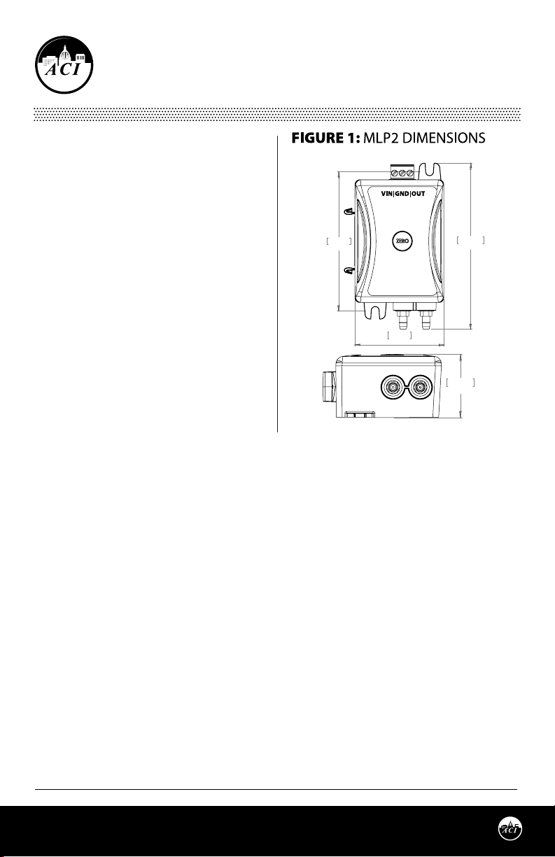
88.9m88.9mmm
3.500i3.500inn
57.1m57.1mmm
2.250i2.250inn
106.3m106.3mmm
4.185i4.185inn
MEDIA
The MLP2 can be used to monitor the dierential
pressure in any application that uses dry air or
inert gas.
34.4m34.4mmm
1.354i1.354inn
MOUNTING INSTRUCTIONS
Using the two #8 x 3/4” self drilling mounting screws supplied by ACI, mount the unit vertically with
the brass fittings pointing towards the ground. Attach the unit to the mounting surface using the
two mounting openings located on the top and bottom flanges. This ensures that any condensation
that may form in the tubing does not have an effect on the pressure sensor. If mounting the unit
horizontally, a slight zero shift may occur and care must be taken to prevent moisture from building up
in the sensor. For best results, all tubing lengths should be limited to a maximum length of 75 feet (23
meters).
DIN RAIL MOUNTING
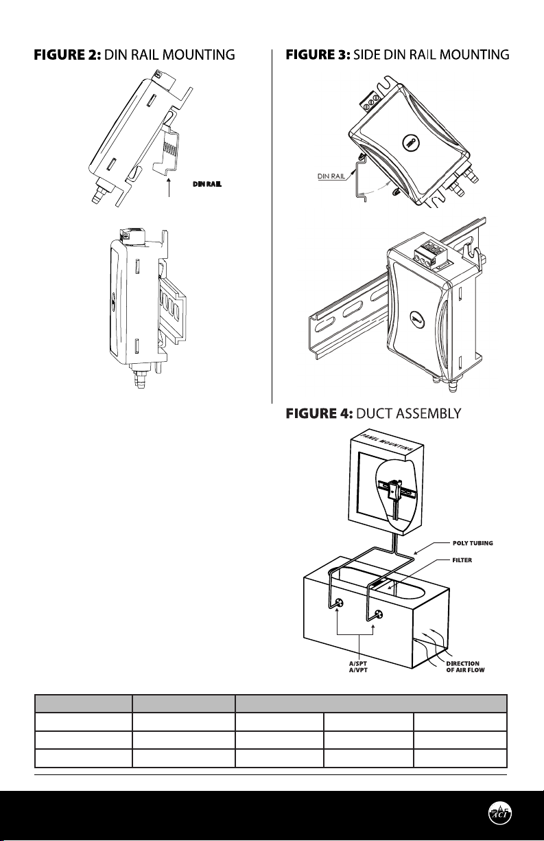
The MLP2 oers two options for DIN Rail mounting: rear and side mount. The rear DIN rail mount is
integrated into the enclosure. The side mount DIN adapter is included with the package. The side mount
oers a much thinner prole for higher density panels. - See Figure 2 or Figure 3 (pg. 2)
To install the side mount DIN adapter, the front cover must be removed rst. The cover can be pried out
with a at blade screw driver on the upper edge, or on the two side slots. The clip can then be slid into
position. Once the clip is inserted, snap the front cover into place.
Page 1
Automation Components, Inc.
2305 Pleasant View Road | Middleton, WI 53562
Phone: 1-888-967-5224 | Website: workaci.com
Version: 12.0
I0000791
Page 2
WIRING INSTRUCTIONS
Shielded cable with 14 to 24AWG conductors is
recommended. Use the Wiring Connections table
below to determine the proper wiring for your
application. Insert the wire into the depluggable
terminal block sockets and tighten the screws. In
some circumstances, it may be easier to remove
the terminal blocks while connecting the wires.
Refer to TABLE 1 (below).
All wiring must comply with local and National
Electric Codes.
Note: When using a shielded cable, be sure to
connect only (1) end of the shield to ground
at the controller. Connecting both ends of the
shield to ground may cause a ground loop. When
removing the shield from the sensor end, make
sure to properly trim the shield to prevent any
chance of shorting.
OUTPUT SIGNAL SUPPLY VOLTAGE WIRE CONNECTIONS
0-5/10VDC AC/DC VIN GND OUT
4-20mA AC VIN GND OUT
4-20mA DC VIN ----- OUT
Page 2
Automation Components, Inc.
2305 Pleasant View Road | Middleton, WI 53562
Phone: 1-888-967-5224 | Website: workaci.com
Version: 12.0
I0000791
Page 3

PRESSURE CONNECTIONS
The recommended connection tubing is ¼” O.D. push-on tubing (1/8” – 3/16” I.D.). ACI recommends to
keep the tubing runs as short as possible so as to not aect the response time.
ZERO ADJUSTMENT
Small positive or negative pressure osets can be removed using the Zero push button. Make sure
that there is no pressure at the HI and LO pressure ttings. Additionally, a small piece of tubing can be
connected between the HI and LO brass ttings to neutralize any external pressure eects. Press and
hold the Zero button for 5 seconds. MLP2 will enter zero mode AFTER push button is released. The Zero
adjustment should only be performed with no pressure applied.
CALIBRATION
MLP2 utilizes a digital pot for Span calibration and is factory set. There is no Span potentiometer for
adjustment. In the event you require Span calibration, the unit must be sent back to ACI.
The Oset can be adjusted using the Auto Zero function. Drift is a function of stress relaxation over time
and this results in the oset shifting, and not the span. Periodically re-zeroing the device will eliminate
the eect of drift.
Automation Components, Inc.
2305 Pleasant View Road | Middleton, WI 53562
Phone: 1-888-967-5224 | Website: workaci.com
Page 3
Version: 12.0
I0000791
Page 4
PRODUCT SPECIFICATIONS
4-20mA (250 Load): 16-36 VDC / 24VAC ± 10 %, 50/60 Hz
Supply Voltage:
Supply Current mA:
[Power Consumption]
Output Signals:
Sensor Accuracy: ± 0.5 % FSO (Standard); ± 0.25 % FSO (Optional)
Operating Temperature Range: 32 to 185 °F (0 to 85 °C)
Compensated Temperature Range: 32 to 122 °F (0 to 50 °C)
Humidity: 10 to 95 % RH, non-condensing
Thermal Eects2: ± 0.056 % FSO/ºF (± 0.10 % FSO/ºC)
Warm Up Time: 15 Minutes
Response Time (T95): 4 Seconds
Output Update Rate: 0.5 Second intervals
Zero Function: Pushbutton Zero Function (Recommended after 15 minutes warm up)
Proof Pressure [Burst Pressure]:
Media Types: Dry air or inert non-conductive gases
Din Rail Mounting: 35 mm (U.S. Patent No. 7,416,421)
Wiring Connections [Wire Size]:
Terminal Block Torque Rating: 4.43 to 5.31 in-lbs. (0.5 to 0.6 Nm)
Tubing Size Accepted: 0.250”(6.35mm) O.D. x 0.170”(4.318mm) I.D. | Push-On Flexible Poly Tubing
Enclosure Material [Flame Rating]: Polycarbonate [UL 94 V-0]
WARRANTY
The ACI MLP2 sensors are covered by ACI’s Five (5) Year Limited Warranty, which is located in the front of
ACI’S SENSORS & TRANSMITTERS CATALOG or can be found on ACI’s website: www.workaci.com.
4-20mA (500 Load): 21-36 VDC / 24VAC ± 10 %, 50/60 Hz
0-5 VDC: 12-36 VDC / 24VAC ± 10 %, 50/60 Hz
0-10 VDC: 16-36 VDC / 24VAC ± 10 %, 50/60 Hz
4-20 mA Output: 23 mA minimum [0.83 VA]
VDC Output Signals: 5 mA maximum [0.18 VA]
4-20 mA: 2-Wire Loop Powered (Output limited to 20.5 mA Max.)
4-20 mA: 3-Wire, VAC Powered (Output limited to 20.5 mA Max.)
0-5 VDC, 1-6 VDC, or 0-10 VDC: 3-Wire, VAC or VDC Powered
(Output limited to 5.25, 6.25, & 10.25 VDC)
Ranges < 1” wc (248.84 Pa): Proof: 270” wc (67.2 kPa) [Burst: 415” wc
(103.3kPa)]
Ranges > 1” wc (0.2488 kPa) to < 10” wc (2.488 kPa): Proof: 350” wc (87.12
kPa) [Burst: 550” wc (136.9kPa)]
Ranges > 10” wc (2.488 kPa) to < 40” wc (9953.6 kPa): Proof: 562” wc (140
kPa) [Burst: 1004.7” wc (250 kPa)]
3 Position de-pluggable screw terminal block
[14 AWG (1.628 mm²) to 24 AWG (0.5105 mm²)]
W.E.E.E. DIRECTIVE
At the end of their useful life the packaging and product should be disposed of via a suitable recycling
centre. Do not dispose of with household waste. Do not burn.
Page 4
Automation Components, Inc.
2305 Pleasant View Road | Middleton, WI 53562
Phone: 1-888-967-5224 | Website: workaci.com
Version: 12.0
I0000791
 Loading...