

Page 1

USER’S GUIDE
Series SN/SM/SH, MN/MM/MH,
LN/LE, XHF
STANDARD VANE IN-LINE VARIABLE AREA
FLOWMETER CONTROL BOXES WITH
TRANSMITTERS
dwyeromega.com | [email protected]
For latest product manuals:
dwyeromega.com/en-us/pdf-manuals
Page 2

Table of Contents
2 General Vane Piston Switch Manual ................................................................................................. 5
2.1 NAMEPLATES AND PRODUCT ID .......................................................................................................................... 5
2.2 Installation .......................................................................................................................................................... 7
3 Vane/Piston AX/H ............................................................................................................................... 8
3.1 Maximum Dimensions ........................................................................................................................................ 8
3.2 Quick Set Up ....................................................................................................................................................... 9
3.2.1 Wiring Using Pre-Installed Wires: ............................................................................................................................................... 9
3.2.2 Wiring Removing Pre-Installed Wires: ........................................................................................................................................ 9
3.3 Introduction to HART® Field Device Specifications ............................................................................................... 9
3.3.1 Scope .......................................................................................................................................................................................... 9
3.3.2 Purpose ....................................................................................................................................................................................... 9
3.3.3 Who Should Use this Document? ............................................................................................................................................... 9
3.3.4 Abbreviations and Definitions .................................................................................................................................................. 10
3.4 Process Interface ................................................................................................................................................ 10
3.4.1 Magnetic Sensors ..................................................................................................................................................................... 10
3.4.2 Host Interface Analog Output 1: Process Flow ......................................................................................................................... 10
3.5 Dynamic Variables ............................................................................................................................................. 11
3.6 Status Information ............................................................................................................................................. 11
3.6.1 Additional Device Status (Command #48) ................................................................................................................................ 11
3.6.1 Burst Mode ............................................................................................................................................................................... 12
3.6.2 Catch Device Variable ............................................................................................................................................................... 12
3.7 Device-Specific Commands ................................................................................................................................. 12
3.8 Command #128: Read Alarm Setpoints .............................................................................................................. 12
3.8.1 Request Data Bytes ................................................................................................................................................................... 12
3.8.2 Response Data Bytes ................................................................................................................................................................ 12
3.9 Command #129: Write Low Alarm Setpoint ........................................................................................................ 13
3.9.1 Request Data Bytes ................................................................................................................................................................... 13
3.9.2 Response Data Bytes ................................................................................................................................................................ 13
3.9.3 Command-Specific Response Codes ......................................................................................................................................... 13
3.10 Command #131: Reset Totalizer ......................................................................................................................... 13
3.10.1 Request Data Bytes .............................................................................................................................................................. 13
3.10.2 Response Data Bytes ............................................................................................................................................................ 13
3.10.3 Command-Specific Response Codes .................................................................................................................................... 14
3.11 Performance ...................................................................................................................................................... 14
3.11.1 Sampling Rates ..................................................................................................................................................................... 14
3.11.2 Power-Up ............................................................................................................................................................................. 14
3.11.3 Reset ..................................................................................................................................................................................... 14
3.11.4 Self-Test ................................................................................................................................................................................ 14
3.11.5 Command Response Times .................................................................................................................................................. 14
3.1 Annex A: Capability Checklist ............................................................................................................................. 15
4 Vane/Piston AXØ .............................................................................................................................. 16
4.1 Maximum Dimensions ....................................................................................................................................... 16
2 | UFM
Page 3

4.2 Nameplates and Product ID ................................................................................................................................ 17
5 Vane/Piston RX/H ............................................................................................................................. 19
5.1 Maximum Dimensions ....................................................................................................................................... 19
5.2 Installation ......................................................................................................................................................... 23
5.3 References ......................................................................................................................................................... 23
5.4 Device Identification .......................................................................................................................................... 23
5.5 Product Overview .............................................................................................................................................. 25
5.6 Process Interface ................................................................................................................................................ 25
5.6.1 Magnetic Sensors ..................................................................................................................................................................... 25
5.6.2 Host Interface: Process Flow .................................................................................................................................................... 25
5.7 Status Information ............................................................................................................................................. 26
5.7.1 Extended Device Status ............................................................................................................................................................ 26
5.8 Universal Commands ......................................................................................................................................... 27
5.9 Common-Practice Supported Commands ........................................................................................................... 27
5.9.1 Command-Specific Response Codes ......................................................................................................................................... 27
5.10 Command #130: Write High Alarm Setpoint ....................................................................................................... 28
5.10.1 Request Data Bytes .............................................................................................................................................................. 28
5.10.2 Response Data Bytes ............................................................................................................................................................ 28
5.10.3 Command-Specific Response Codes .................................................................................................................................... 28
5.11 Tables ................................................................................................................................................................ 28
5.11.1 Flow Unit Codes ................................................................................................................................................................... 28
5.11.2 Unit Conversion .................................................................................................................................................................... 29
5.12 Perfomance .............................................................................................................. ............................................29
5.12.1 Busy and Delayed-Response ................................................................................................................................................ 29
5.12.2 Long Messages ..................................................................................................................................................................... 29
5.12.3 Non-Volatile Memory ........................................................................................................................................................... 29
5.12.4 Modes .................................................................................................................................................................................. 29
5.12.5 Write Protection ................................................................................................................................................................... 29
5.12.6 Damping ............................................................................................................................................................................... 29
5.13 Annex b. Default Configuration .......................................................................................................................... 29
6 Vane/Piston TX/H .............................................................................................................................. 30
6.1 Maximum Dimensions ....................................................................................................................................... 30
6.2 Installation ......................................................................................................................................................... 33
6.3 Device Identification .......................................................................................................................................... 33
6.4 Product Overview .............................................................................................................................................. 34
6.5 Process Interface ................................................................................................................................................ 34
6.5.1 Magnetic Sensors ..................................................................................................................................................................... 34
6.5.2 Host Interface: Process Flow .................................................................................................................................................... 34
6.1 Status Information ............................................................................................................................................. 35
6.1.1 Extended Device Status ............................................................................................................................................................ 35
6.2 Universal Commands ......................................................................................................................................... 36
3 | UFM
Page 4

6.3 Common-Practice Supported Commands ........................................................................................................... 36
6.3.1 Burst Mode ............................................................................................................................................................................... 36
6.3.2 Catch Device Variable ............................................................................................................................................................... 36
6.4 Device-Specific Commands ................................................................................................................................. 36
6.5 Command #129: Write Low Alarm Setpoint ........................................................................................................ 37
6.5.1 Request Data Bytes ................................................................................................................................................................... 37
6.5.2 Response Data Bytes ................................................................................................................................................................ 37
6.5.3 Command-Specific Response Codes ......................................................................................................................................... 37
6.6 Command #131: Reset Totalizer ......................................................................................................................... 37
6.6.1 Request Data Bytes ................................................................................................................................................................... 37
6.6.2 Response Data Bytes ................................................................................................................................................................ 37
6.6.3 Command-Specific Response Codes ......................................................................................................................................... 38
6.7 Performance ...................................................................................................................................................... 38
6.7.1 Sampling Rates ......................................................................................................................................................................... 38
6.7.2 Power-Up .................................................................................................................................................................................. 38
6.7.3 Reset ......................................................................................................................................................................................... 38
6.7.4 Self-Test .................................................................................................................................................................................... 38
6.7.5 Command Response Times ....................................................................................................................................................... 38
6.8 Annex A: Capability Checklist ............................................................................................................................. 39
7 Vane/Piston TX/TXL .......................................................................................................................... 40
7.1 Nameplates and Product ID ................................................................................................................................ 40
7.2 Set Low Flow Alarm ............................................................................................................................................ 43
4 | UFM
Page 5
1 General Vane Piston Switch Manual
A0
L0
Z0
A1
L1
Z1
A1B
L1B
Z1B
A3
L3
Z3
A61
L61
Z61
A71
L71
Z71
A3
L3
Z3
A4
L4
Z4
A62
L62
Z62
A72
L72
Z72
A2
L2
Z2
Installation and Operation Manual for series: LL, LP, LH, SN, SM, SH, MN, MM ,MH, SX and MX for A, L or Z
control boxes with 0, 1 or 2 switches.
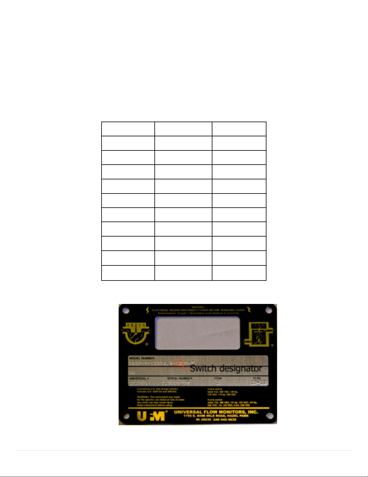
1.1 NAMEPLATES AND PRODUCT ID
This manual applies to all vane/piston meters that have one of the designators in the model codes shown
in the table shown below. This can be seen on the name plate example.
Table 1: Model code designations for zero, one, two switches
Figure 1: Name Plate Example
5 | UFM
Page 6
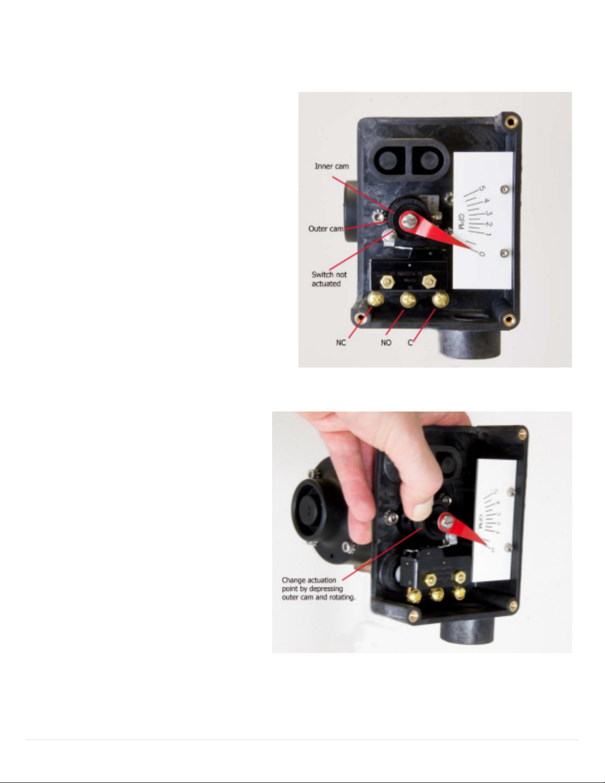
Wire directly to the switch terminal screws.
Figure 2: Device overview
Figure 3: Cam adjustment
In
one switch units, the cam is easily
adjusted by depressing the outer ring
and turning it to the desired position
6 | UFM
Page 7

WARNING: This instrument was made for the specific use stated at the time of order. Any other use may cause
Switch Identification
Switch Description
Electrical Ratings
Model Code Designator: 1 or 2
SPDT – (3 wire)
(1 or 2 switches may be
provided)
15A – 125VAC, 250VAC, 480VAC; ⅛HP –
125VAC, ¼HP – 250VAC
Model Code Designator: 1B or 2B
SPDT – (3 wire)
High Vibration
20A – 125VAC, 250VAC, 480VAC; ½A –
125VDC, ¼A -250VDC; 1HP – 125VAC,
2HP – 250VAC
Model Code Designator: 61 or 62
SPDT –
High Temperature
15A – 125VAC, 250VAC, 480VAC; ½A –
125VDC, ¼A -250VDC; ⅛HP – 125VAC,
¼HP – 250VAC
Model Code Designator: 71 or 72
SPDT –
Gold Contact
15A – 125VAC, 250VAC, 480VAC; ⅛HP –
125VAC, ¼HP – 250VAC
Model Code Designator: 3 or 4
SPDT – (4 wire)
Single-Break Form Z
15A – 125VAC, 250VAC, 480VAC; 1A –
125VDC, ½A -250VDC; ¼HP – 125VAC,
½HP – 250VAC
injury. Read instructions before using the device.
Supply Connections—Wire Sizes: Wire used to connect any Switches included must be in accordance with all
local and national codes. Wire size and insulation ratings should support actual loads. See also Switch Ratings
below. In all cases, wire must be, as a minimum, 20 AWG Teflon insulated rated at 600V and 200°C. It is
recommended to include a disconnect switch or circuit breaker near this equipment.
Electrical Switch Ratings:
Table 2: Electrical Switch Ratings
1.2 Installation
For best results, the meters may be installed in any position as long as proper piping installation
requirements are observed. This includes sufficient support of adjacent piping to minimize the system’s
inherent vibration. Unions of the same pipe size and full port isolation ball valves may be installed for ease
of removal and servicing of equipment, if necessary.
If Teflon® tape or pipe sealant is used, the user must ensure that no loose parts become wrapped around
the bluff or the flow sensor when the flow starts.
7 | UFM
Page 8
2 Vane/Piston AX/H
Installation and Operation Manual Series: LL, LP, LH, SN, SM, SH, MN, MM, MH, SX and MX Used with
control boxes: A, L, or Z with 4-20 mA
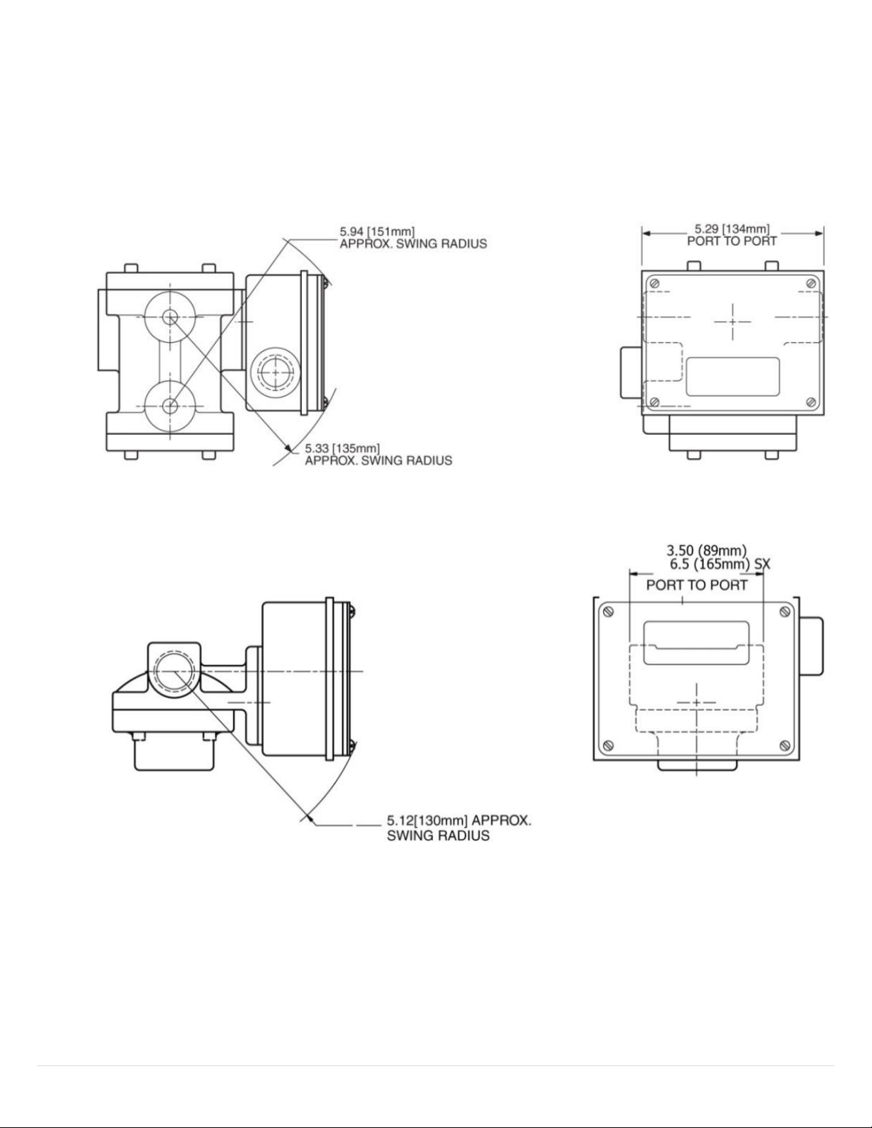
2.1 Maximum Dimensions
Figure 4: LL, LP, and LH dimensions
Figure 5: SX, SN, SM, and SH dimensions
8 | UFM
Page 9
2.2 Quick Set Up
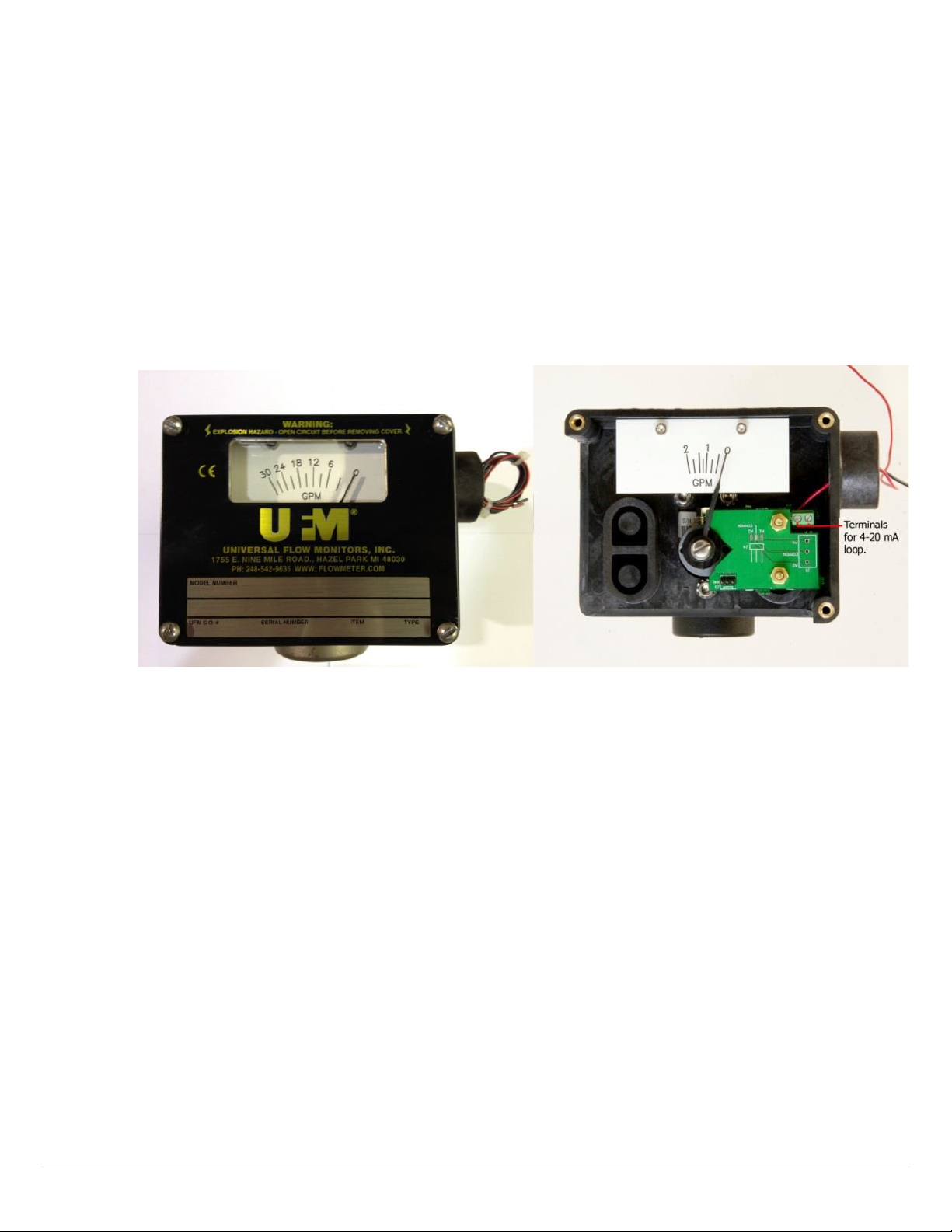
2.2.1 Wiring Using Pre-Installed Wires:
Complete the loop circuit using the 2 pre-installed 18”, 22AWG wires provided.
IMPORTANT: Observe polarity—The red wire is positive (+), and the black wire is negative (-).
2.2.2 Wiring Removing Pre-Installed Wires:
Open cover and remove pre-installed wires. Connect a twisted wire pair (not provided) to the
terminals observing the polarity marked on the PC board. The units are shipped with a red wire
connected to the positive (+) terminal, and a black wire connected to the negative (-) terminal. The
wire may be up to AWG 14 size, but no smaller than AWG22.
Figure 6: Terminals for 4-20 mA loop
2.3 Introduction to HART® Field Device Specifications
2.3.1 Scope
The Universal Flow Monitors water flow transmitter, model ME Transmitter complies with HART
Protocol Revision 7.0. This document specifies all the device specific features and documents
HART Protocol implementation details (e.g., the Engineering Unit Codes supported). The
functionality of this Field Device is described sufficiently to allow its proper application in a process
and its complete support in HART capable Host Applications.
2.3.2 Purpose
This specification is designed to complement other documentation (e.g., the installation manuals
specific to SN/SM/SH, MN/MM/MH/, LL/LP/LH, LN/LE and XHF model flow meters) by providing a
complete, unambiguous description of this Field Device from a HART Communication perspective
2.3.3 Who Should Use this Document?
The specification is designed to be a technical reference for HART capable Host Application
Developers, System Integrators and knowledgeable End Users. It also provides functional
specifications (e.g., commands, enumerations and performance requirements) used during Field
Device development, maintenance and testing. This document assumes the reader is familiar with
HART Protocol requirements and terminology.
9 | UFM
Page 10
2.3.4 Abbreviations and Definitions
ADC Analog to Digital Converter
CPU Central Processing Unit (of microprocessor)
DAC Digital to Analog Converter
EEPROM Electrically-Erasable Read-Only Memory
ROM Read-Only Memory
PV Primary Variable
SV Secondary Variable
HCF HART Communication Foundation
FSK Frequency Shift Keying Physical Layer
2.4 Process Interface
2.4.1 Magnetic Sensors
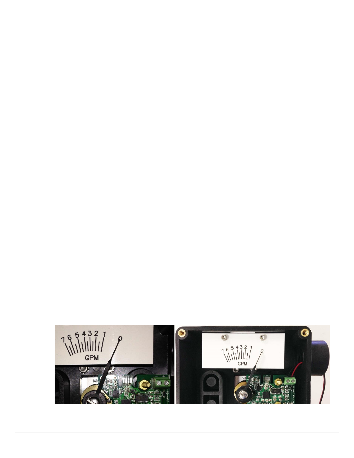
There are two built-in hall-effect sensors measuring the rotation of a permanent magnet that is mounted
onto the flowmeter shaft. As the shaft rotates with flow, the sensors provide analog readings that are in turn
converted to a digital value by and A/D converter. The digital values are then processed by the
microcontroller and linearized, and subsequently converted to a scaled analog output via a D/A converter in
the range of 4 to 20 mA.
2.4.2 Host Interface Analog Output 1: Process Flow
The two-wire 4-20mA current loop is connected to two terminals on the transmitter circuit board. Depending
on the product used, one of the two configurations are offered for field wiring.
The first option allows the user to directly connect the loop wires to the terminals on the PCB. The
correct polarity is shown in the pictures below, where the red wire is connected to the (+) terminal
and the black wire is connected to the (–) terminal.
Figure 7: PCB Polarity wiring
10 | UFM
Page 11

2.5 Dynamic Variables
Meaning
Units
PV
Volumetric Flow Reading
GPM, CMH,
LPM
SV
Totalizer Value based on
PV
Follows PV Units
Bit Mask
Definition
Conditions to set bit
0x80(bit 7)
Device Malfunction
None
0x40(bit 6)
Configuration Changed
Any change in device configuration
0x20(bit 5)
Cold start
Set any time power is cycled
0x10(bit 4)
More Status Available
Triggers when either alarm is active
0x08(bit 3)
Loop Current Fixed
None
0x04(bit 2)
Loop Current Saturated
Occurs when loop current reaches upper limit
0x02(bit 1)
Non-Primary Variable out of limits
None
0x01(bit 0)
Primary Variable Out of limits
Occurs when PV is being limited due to
exceeding calibrated limitations
Bit Mask
Description
Conditions
0x80
Undefined
NA
0x40
Undefined
NA
0x20
Undefined
NA
0x10
Undefined
NA
0x08
Undefined
NA
0x04
Undefined
NA
0x02
High Alarm
High Alarm is active if set
0x01
Low Alarm
Low Alarm is active if set
Two Dynamic Variables are implemented.
Table 3: Dynamic Variables table
The PV is derived using a calibrated linearization table applied to A/D converter readings of hall-effect
sensors.
The SV is based on a 5ms timer and is updated based on the current reading of flow.
Both PV and SV values are smoothed.
2.6 Status Information
Table 4: Device Status table
When Bit 4 is set, Host should send Command 48 to determine which alarm is active.
2.6.1 Additional Device Status (Command #48)
Command #48 returns 9 bytes of data, with the following status information:
Table 5: Device Specific Status Byte 0 table
11 | UFM
Page 12
2.6.1 Burst Mode
Byte
Format
Description
None
Byte
Format
Description
0
Enum
PV Unit value
1-4
Float
High Alarm Setpoint
5-8
Float
Value of High Alarm Setpoint
This Field Device does not support Burst Mode.
2.6.2 Catch Device Variable
This Field Device does not support Catch Device Variable.
2.7 Device-Specific Commands
The following device-specific commands are implemented:
128 Read Alarm Setpoints
129 Write Low Alarm Setpoint
130 Write High Alarm Setpoint
131 Reset Totalizer
2.8 Command #128: Read Alarm Setpoints
Reads the High and Low Alarm Setpoints. If zero, the alarm is disabled.
2.8.1 Request Data Bytes
Table 6: Request Data Bytes table
2.8.2 Response Data Bytes
Table 7: Response Data Bytes table
12 | UFM
Page 13
2.9 Command #129: Write Low Alarm Setpoint
Byte
Format
Description
0-3
Float
Low Alarm Setpoint
Byte
Format
Description
0
Enum
PV Unit value
1-4
Float
Low Alarm Setpoint
Code
Class
Description
0
Success
No Command-Specific Errors
1-15
Undefined
16
Error
Access Restricted
17-31
Undefined
32
Error
Busy
33-127
Undefined
Byte
Format
Description
None
Byte
Format
Description
None
Writes the setpoint for the Low Alarm.
2.9.1 Request Data Bytes
Table 8: Request Data Bytes table
2.9.2 Response Data Bytes
Table 9: Response Data Bytes table
2.9.3 Command-Specific Response Codes
Table 10: Command-Specific Response Codes table
2.10 Command #131: Reset Totalizer
Resets the totalizer to zero.
2.10.1 Request Data Bytes
2.10.2 Response Data Bytes
Table 11: Request Data Bytes table
Table 12: Response Data Bytes table
13 | UFM
Page 14

2.10.3 Command-Specific Response Codes
Code
Class
Description
0
Success
No Command-Specific Errors
1-15
Undefined
16
Error
Access Restricted
17-31
Undefined
32
Error
Busy
33-127
Undefined
PV digital value calculation
10 per second
SV digital value calculation
10 per second
Analog output update
10 per second
Minimum
20ms
Typical
50ms
Maximum
100ms
Table 13: Command-Specific Response Codes table
2.11 Performance
2.11.1 Sampling Rates
Typical sampling rates are shown in the following table.
Table 14: Sampling Rates table
2.11.2 Power-Up
The device is typically ready within 1 second of power-up. Totalizer is initialized to zero.
2.11.3 Reset
Command 42 ("Device Reset") causes the device to reset its microcontroller. The resulting restart is
identical to the normal power up sequence.
2.11.4 Self-Test
Self-Test is not supported.
2.11.5 Command Response Times
Table 15: Command Response Times table
14 | UFM
Page 15

2.1 Annex A: Capability Checklist
Manufacturer, model and revision
Universal Flow, ME Transmitter, Rev1
Device type
Transmitter
HART revision
7.0
Device Description available
No
Number and type of sensors
2 internal
Number and type of actuators
0
Number and type of host side signals
1: 4 - 20mA analog
Number of Device Variables
4
Number of Dynamic Variables
2
Mappable Dynamic Variables?
No
Number of common-practice commands
5
Number of device-specific commands
4
Bits of additional device status
2
Alternative operating modes?
No
Burst mode?
No
Write-protection?
No
Table 16: Capability Checklist table
15 | UFM
Page 16
3 Vane/Piston AXØ
Installation and Operation Manual Series: LL, LP, LH, SN, SM, SH, MN, MM ,MH, SX and MX for A, L or Z
control boxes with transmitter.
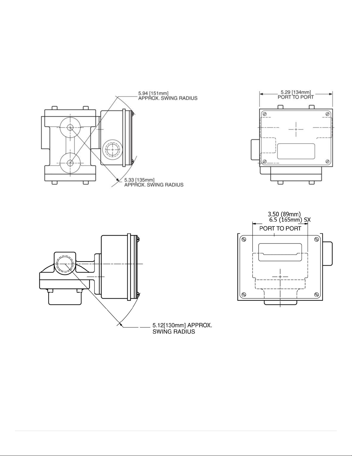
3.1 Maximum Dimensions
Figure 8: Figure 9: LL, LP, and LH dimensions
Figure 10: SX, SN, SM, and SH dimensions
16 | UFM
Page 17
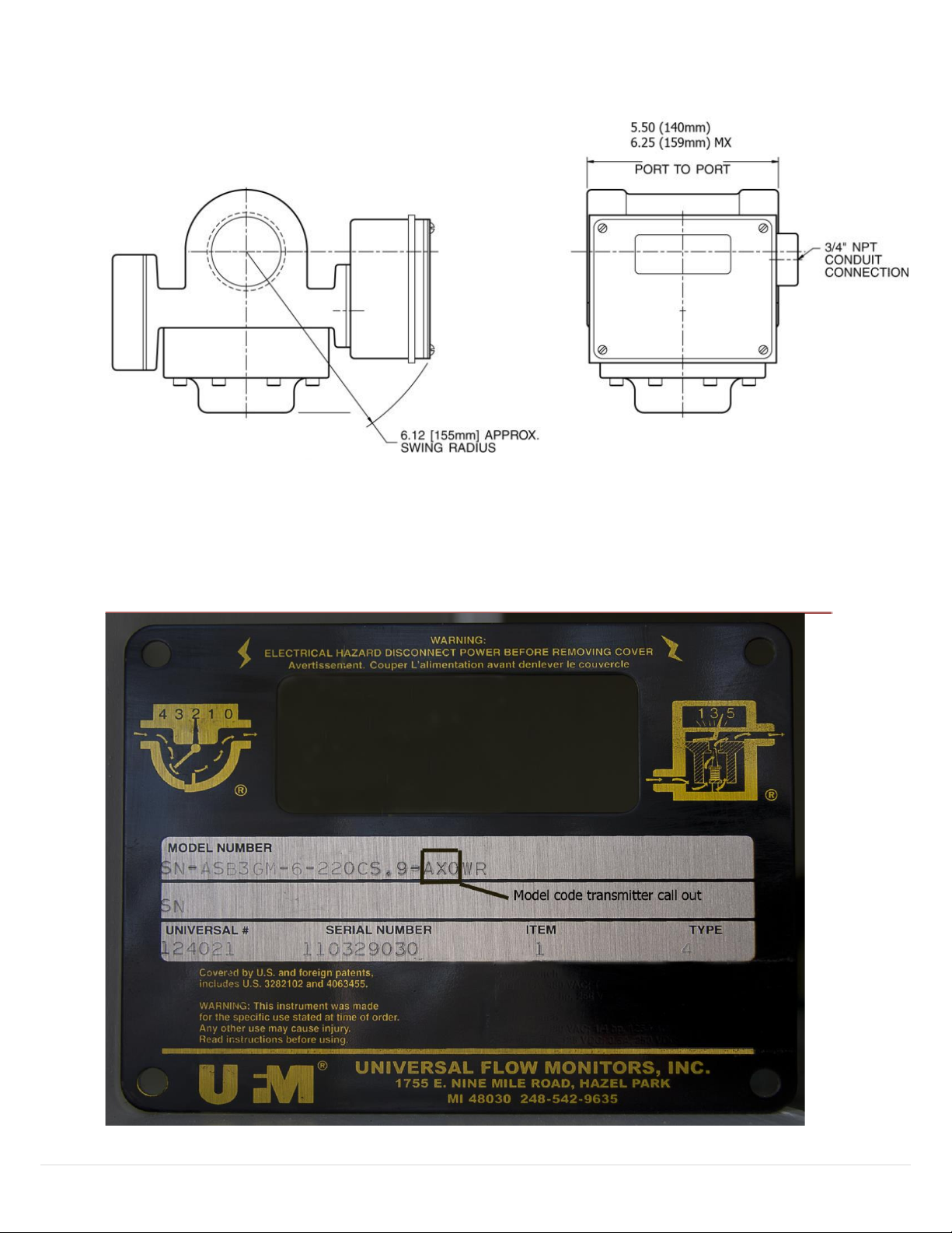
Figure 11: MN, MM, MH, and MX
3.2 Nameplates and Product ID
This manual applies to all vane/piston meters that have the designator “AX0”, “LX0” or “ZX0” in the model
code. This can be seen on the name plate as shown below.
Figure 12: Nameplate and Product ID
17 | UFM
Page 18

18 | UFM
Page 19
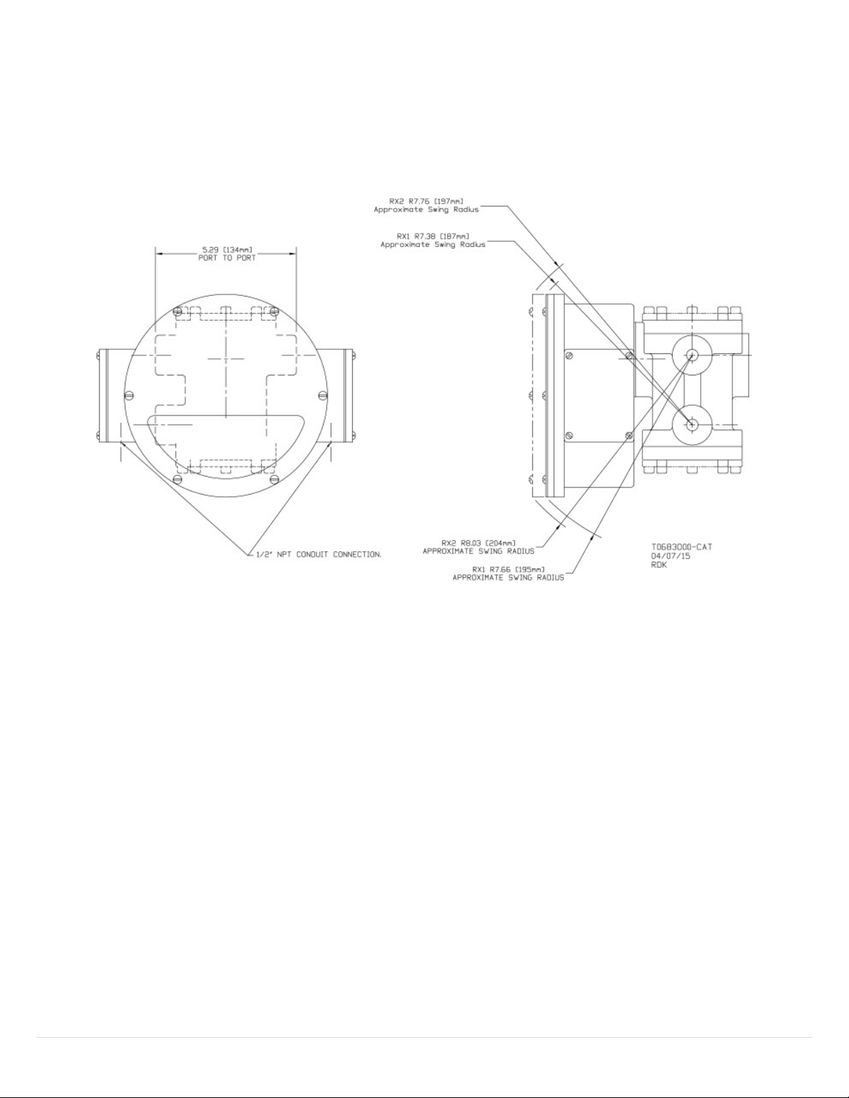
4 Vane/Piston RX/H
Installation and Operation Manual Series: LL, LP, LH, SN, SM, SH, MN, MM, MH, SX, MX, LN, LE and XHF
Used with R control boxes with 4-20 mA transmitter or HART and optional mechanical switches.
4.1 Maximum Dimensions
Figure 13: LL, LP, and LH Dimensions
19 | UFM
Page 20
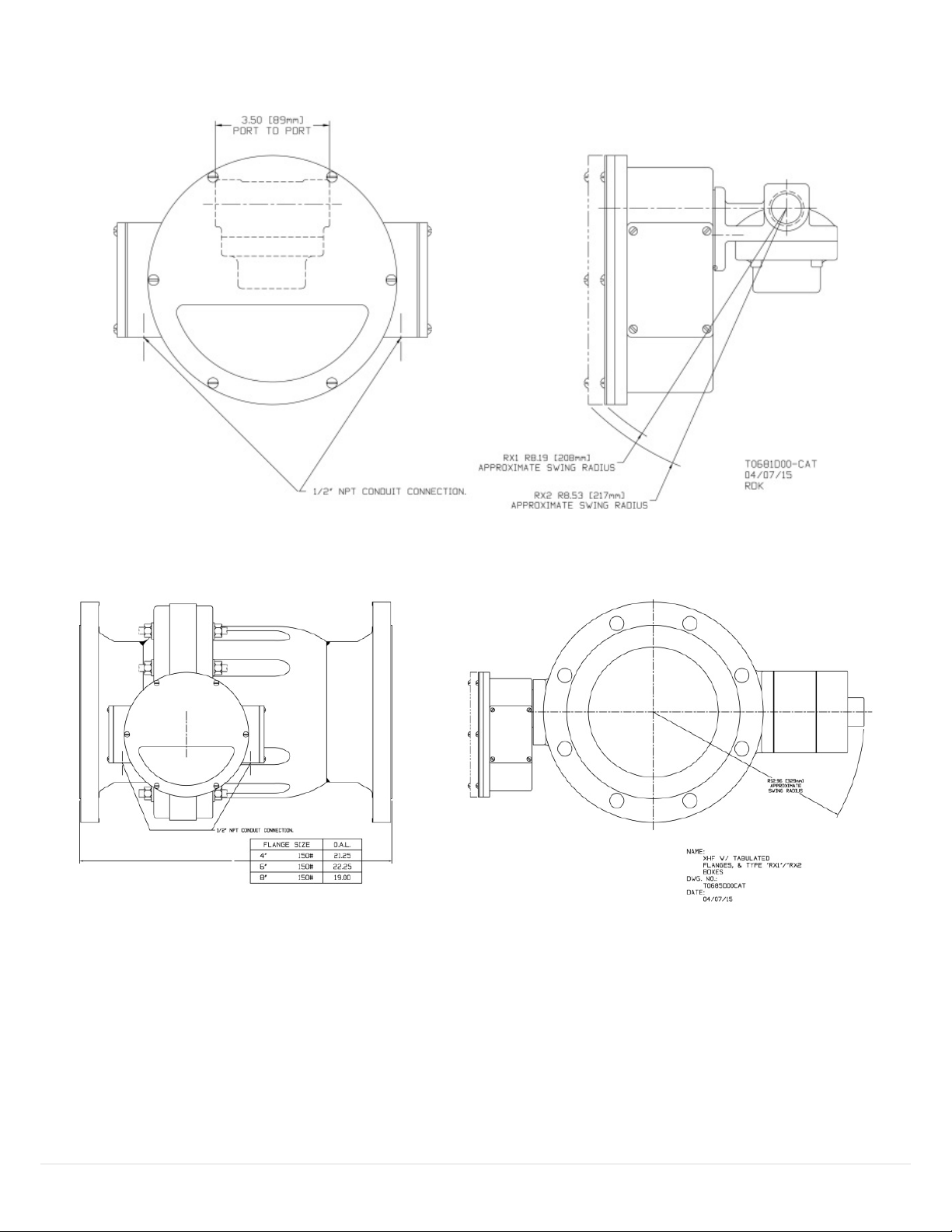
Figure 14: SX, SN, SM, and SH Dimensions
Figure 15: XHF Dimensions
20 | UFM
Page 21
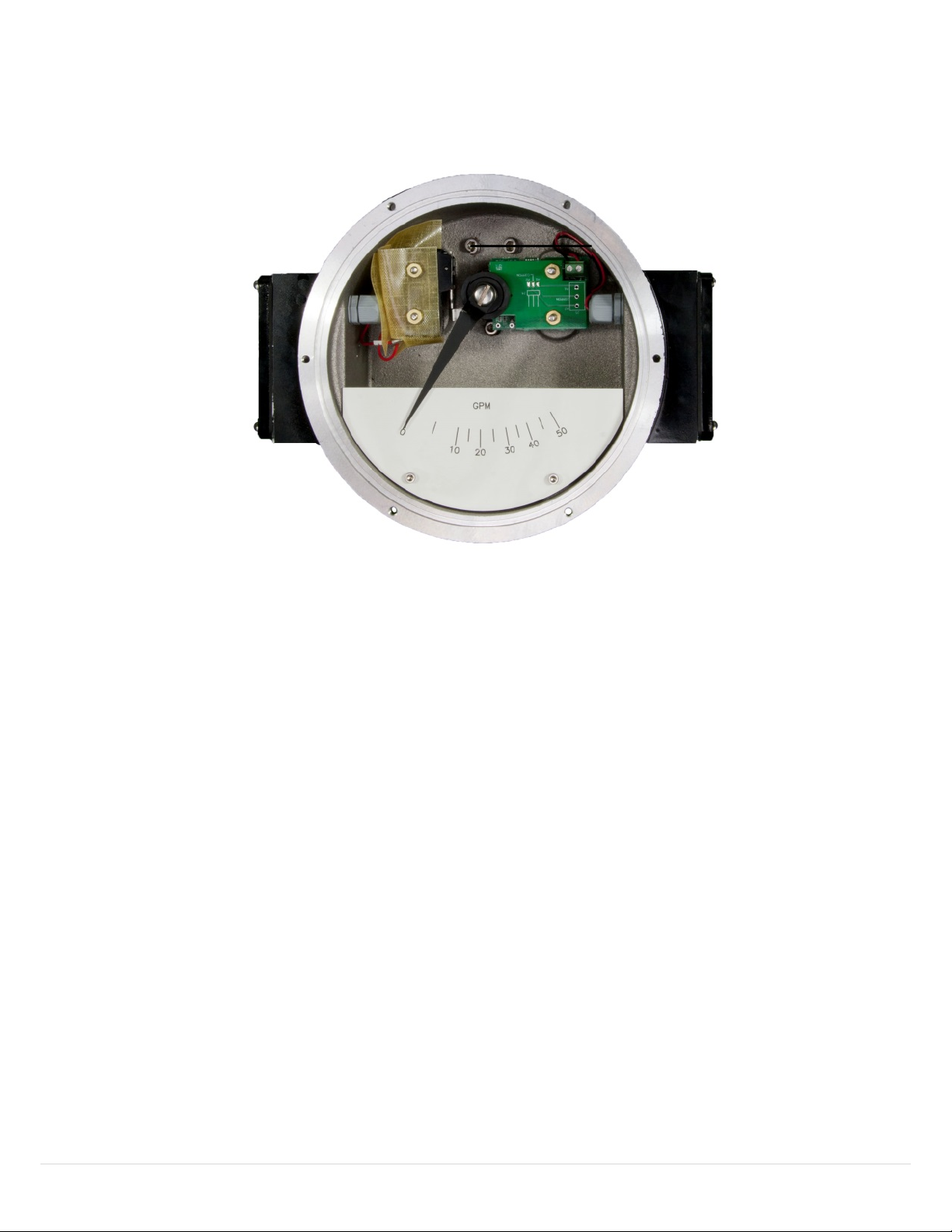
Figure 16: R Box shown open with optional mechanical switch
21 | UFM
Page 22
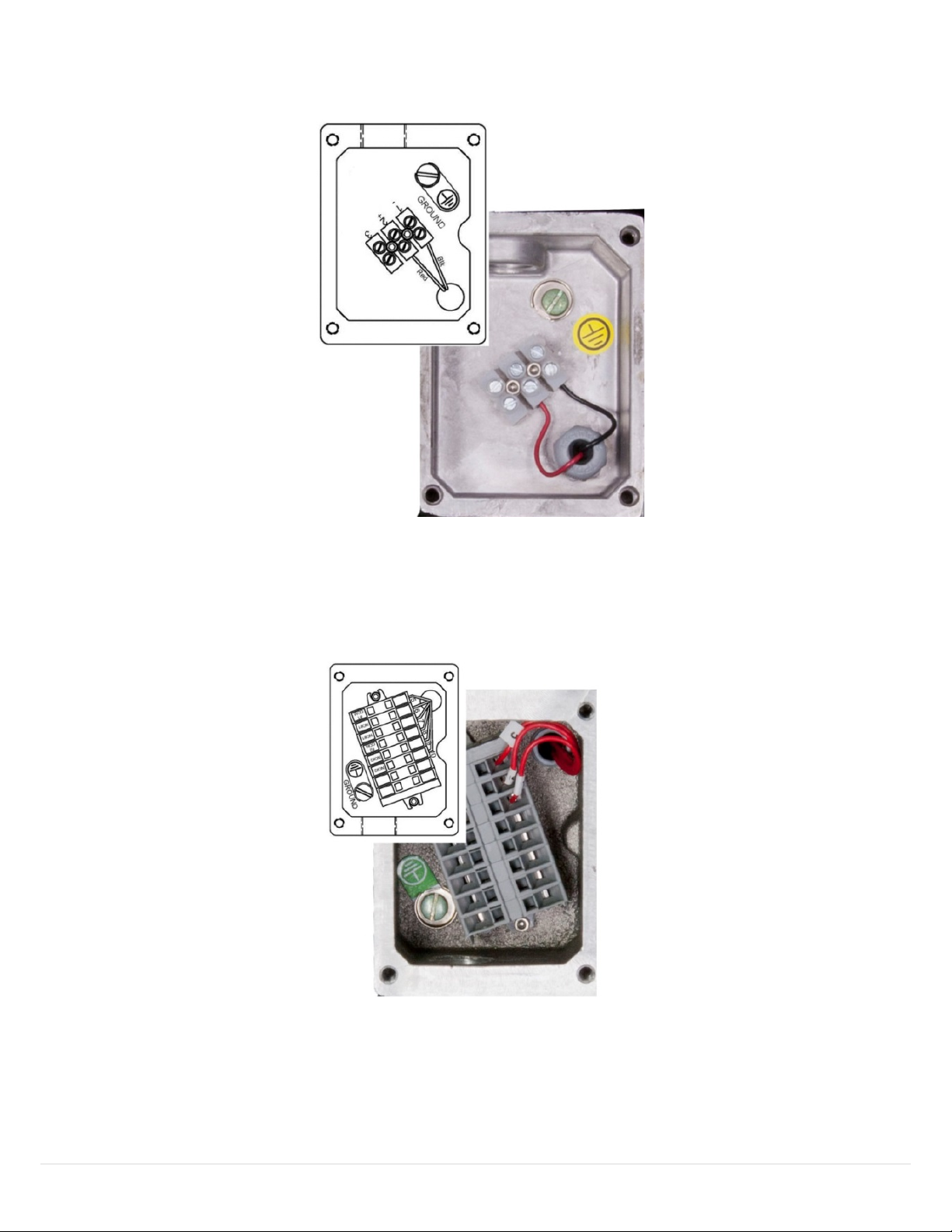
Figure 17: Transmitter Wiring with or without HART
Figure 18: Mechanical (Optional) Switch Wiring
!
22 | UFM
Page 23

4.2 Installation
For best results, the meters may be installed in any position as long as proper piping installation requirements are
observed. This includes sufficient support of adjacent piping to minimize the system’s inherent vibration. Unions of
the same pipe size and full port isolation ball valves may be installed for ease of removal and servicing of
equipment, if necessary.
Figure 19: Maximum Load vs. Supply Voltage table
4.3 References
HART Smart Communications Protocol Specification. HCF_SPEC-12. Available from the HCF.
Installation manuals specific to SN/SM/SH, MN/MM/MH/LL/LP/LH,LN/LE and XHF model flow meters as
manufactured by Universal Flow Monitors, Inc.
4.4 Device Identification
23 | UFM
Page 24

Manufacturer Name:
Universal Flow
Model Name(s):
ME Transmitter
Manufacture ID Code:
24692
(6074 Hex)
Device Type Code:
230
(E1EF Hex)
HART Protocol Revision
7.0
Device Revision:
1
Number of Device Variables
4
Physical Layers Supported
FSK
Physical Device Category
Transmitter, Non-DC-isolated Bus Device
Figure 20: Device Identification
24 | UFM
Page 25
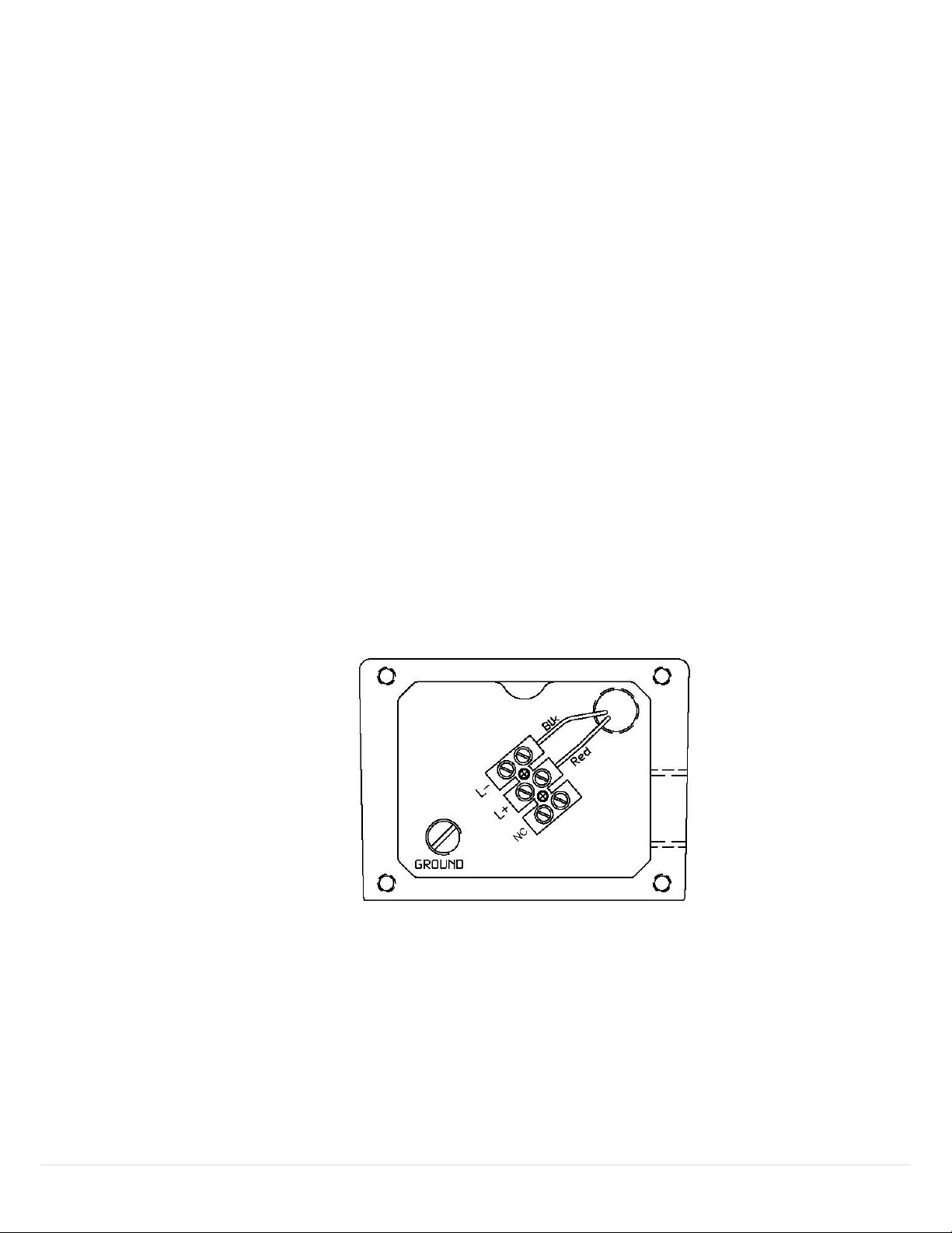
4.5 Product Overview
The ME Transmitter is a two-wire loop-powered flow transmitter, with a 4-to-20mA output. This transmitter uses a
non-contact magnetic encoder for measuring the displacement of the shaft/pointer on standard UFM flowmeters.
It is an add-on feature to SN/SM/SH,MN/MM/MH,LL/LP/LH,LN/LE and XHF model flow meters as manufactured by
Universal Flow Monitors, Inc. The ME Transmitter replaces the earlier models Digital Transmitters that utilized a
potentiometer, providing improved accuracy while maintaining 100% compatibility. The analog output of this
device is linear with flow over the working range of all supported flowmeters.
4.6 Process Interface
4.6.1 Magnetic Sensors
There are two built-in hall-effect sensors measuring the rotation of a permanent magnet that is mounted
onto the flowmeter shaft. As the shaft rotates with flow, the sensors provide analog readings that are in turn
converted to a digital value by and A/D converter. The digital values are then processed by the
microcontroller and linearized, and subsequently converted to a scaled analog output via a D/A converter in
the range of 4 to 20 mA.
4.6.2 Host Interface: Process Flow
The two-wire 4-20mA current loop is connected to two terminals on the transmitter circuit board. Depending
on the product used, one of the two configurations are offered for field wiring.
A secondary terminal strip away from the PCB (mounted in a separate compartment of the flowmeter) and is
marked L+ and L-. The red wire connects the (+) terminal on the PCB to L+ and the black wire connects the (–)
terminal on the PCB to L-.
Figure 21: PCB Wiring
This is the only output from this transmitter, representing the process flow measurement, linearized and
scaled according to the configured range of the instrument. This output corresponds to the Primary Variable.
HART Communication is supported on this loop.
25 | UFM
Page 26

A guaranteed linear over-range is provided. The up-scale current of 24mA can indicate device malfunction.
Direction
Values (percent of range)
Values (mA or V)
Linear over-range
Down
0% ± 0.5%
3.92 to 4.08 mA
Up
+106.25% ± 0.1%
20.84 mA to 21.16 mA
Device malfunction
indication
Down
N/A
N/A
Up
+125.0% ± 0.1%
23.98 mA to 24.02 mA
Maximum current
+106.25% ± 1%
20.84 mA to 21.16 mA
Multi-Drop current draw
4.0 mA
Lift-off voltage
10.5 V
Bit Mask
Definition
Conditions to set bit
0x80(bit 7)
Device Malfunction
None
0x40(bit 6)
Configuration Changed
Any change in device configuration
0x20(bit 5)
Cold start
Set any time power is cycled
0x10(bit 4)
More Status Available
Triggers when either alarm is active
0x08(bit 3)
Loop Current Fixed
None
0x04(bit 2)
Loop Current Saturated
Occurs when loop current reaches upper limit
0x02(bit 1)
Non-Primary Variable out of limits
None
0x01(bit 0)
Primary Variable Out of limits
Occurs when PV is being limited due to
exceeding calibrated limitations
Current values are shown in the table below.
4.7 Status Information
Table 17: Current Values table
Table 18: Device Status table
When Bit 4 is set, Host should send Command 48 to determine which alarm is active.
4.7.1 Extended Device Status
The Field Device cannot predict, in advance, when the maintenance will be required. Extended Device Status
is unused.
26 | UFM
Page 27
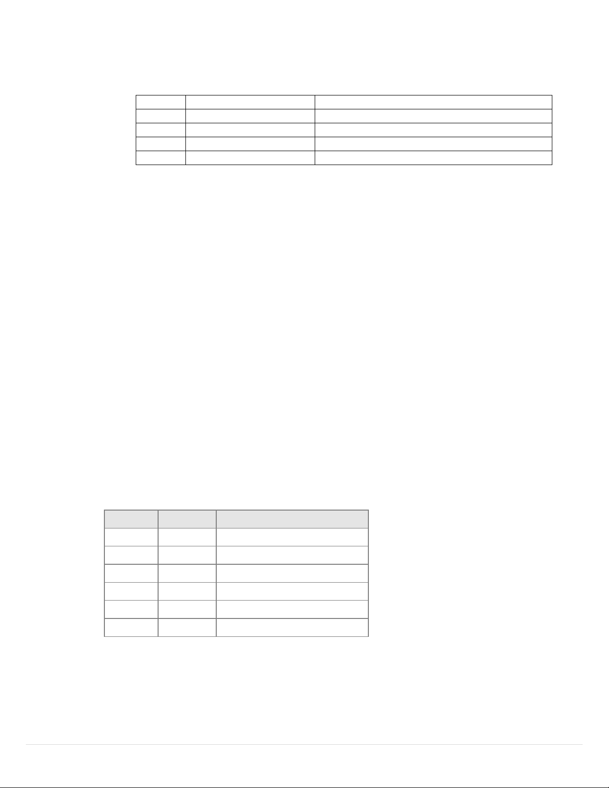
Table 19: Command 48-Byte Data
Byte
Description
Data
0-5
Device Specific Status
Only Byte 0 is used
6
Extended Device Status
Bit 1 will be set when an alarm condition is active.
7
Device Operating Mode
0
8
Standard Status 0
Not used
Code
Class
Description
0
Success
No Command-Specific Errors
1-15
Undefined
16
Error
Access Restricted
17-31
Undefined
32
Error
Busy
33-127
Undefined
"Not used" bits are always set to 0.
Device does not support extended device status, all device status activity is included in the device status
byte.
4.8 Universal Commands
All Universal Commands are supported as specified in the HART Universal Command Specification.
4.9 Common-Practice Supported Commands
The following common-practice commands are implemented:
33 Read Device Variables
35 Write Range Values
42 Perform Master Reset
44 Write PV Units
54 Read Device Variable Information
In command 54 the acquisition period is unused. Values are typically updated every 100ms.
4.9.1 Command-Specific Response Codes
Table 20: Command-Specific Response Codes
27 | UFM
Page 28

4.10 Command #130: Write High Alarm Setpoint
Byte
Format
Description
0-3
Float
High Alarm Setpoint
Byte
Format
Description
0
Enum
PV Unit value
1-4
Float
High Alarm Setpoint
Code
Class
Description
0
Success
No Command-Specific Errors
1-15
Undefined
16
Error
Access Restricted
17-31
Undefined
32
Error
Busy
33-127
Undefined
16
Gallons Per Minute (GPM)
17
Liters Per Minute (LPM)
19
Cubic Meters Per Hour (CMH)
Writes the setpoint for the High Alarm.
4.10.1 Request Data Bytes
Table 21: Request Data Bytes table
4.10.2 Response Data Bytes
Table 22: Response Data Bytes table
4.10.3 Command-Specific Response Codes
Table 23: Command-Specific Response Codes table
4.11 Tables
4.11.1 Flow Unit Codes
Subset of HART Common Unit Codes
Table 24: Flow Unit Codes table
28 | UFM
Page 29

4.11.2 Unit Conversion
New Unit
Previous Unit
Factor
GPM
LPM
0.2642
CMH
4.403
LPM
GPM
3.785
CMH
16.666
CMH
GPM
0.2271
LPM
0.06
Internally, the transmitter uses Gallons per Minute. Conversions are made using a floating point factor.
Values are directly converted from GPM when possible, however Alarm values changed between units are
converted from stored unit value:
Table 25: Unit Conversion table
4.12 Performance
4.12.1 Busy and Delayed-Response
Device busy is not used. Delayed-response is not used.
4.12.2 Long Messages
The largest data field used is in the response to Command 21: 34 bytes including the two status bytes.
4.12.3 Non-Volatile Memory
EEPROM is used to hold the device’s configuration parameters. New data is written within 100ms of
command receipt.
4.12.4 Modes
Fixed current mode is not implemented.
4.12.5 Write Protection
Write-protection is not implemented.
4.12.6 Damping
Damping is not implemented.
4.13 Annex b. Default Configuration
Default configuration is based on a unit-by-unit basis.
29 | UFM
Page 30
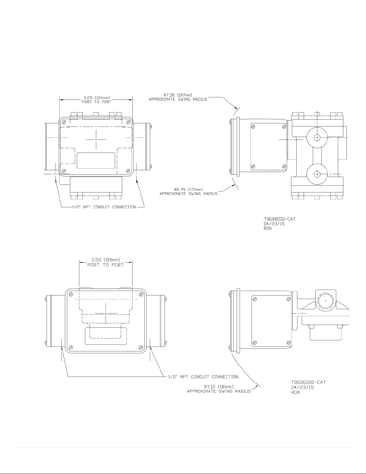
5 Vane/Piston TX/H
Installation and Operation Manual Series: LL, LP, LH, SN, SM, SH, MN, MM, MH, SX, MX, LN, LE and XHF
Used with T control boxes with 4-20 mA transmitter or HART and optional mechanical switches.
5.1 Maximum Dimensions
Figure 22: LL, LP, and LH dimensions
Figure 23: SX, SN, SM, and SH dimensions
30 | UFM
Page 31
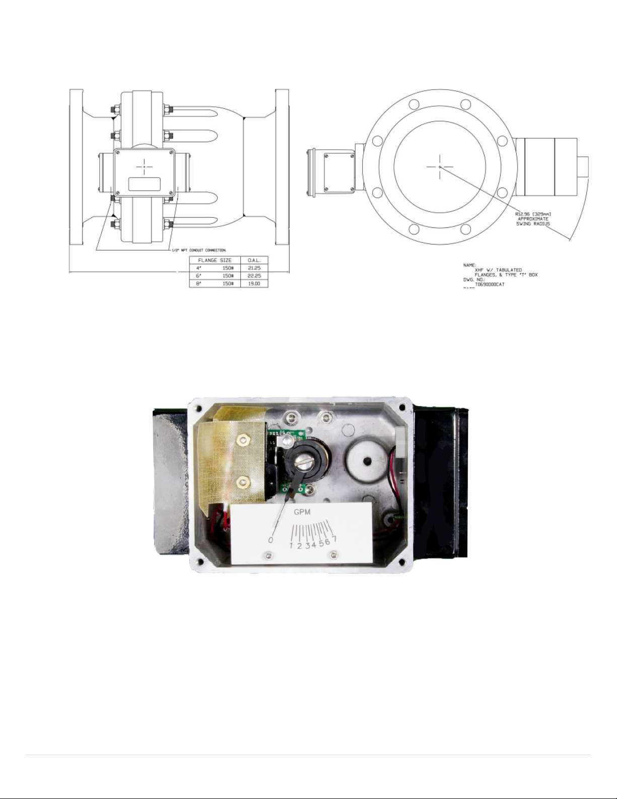
XHF
Figure 24: XHF dimensions
Figure 25: T Box with Optional Switch and Transmitter
31 | UFM
Page 32
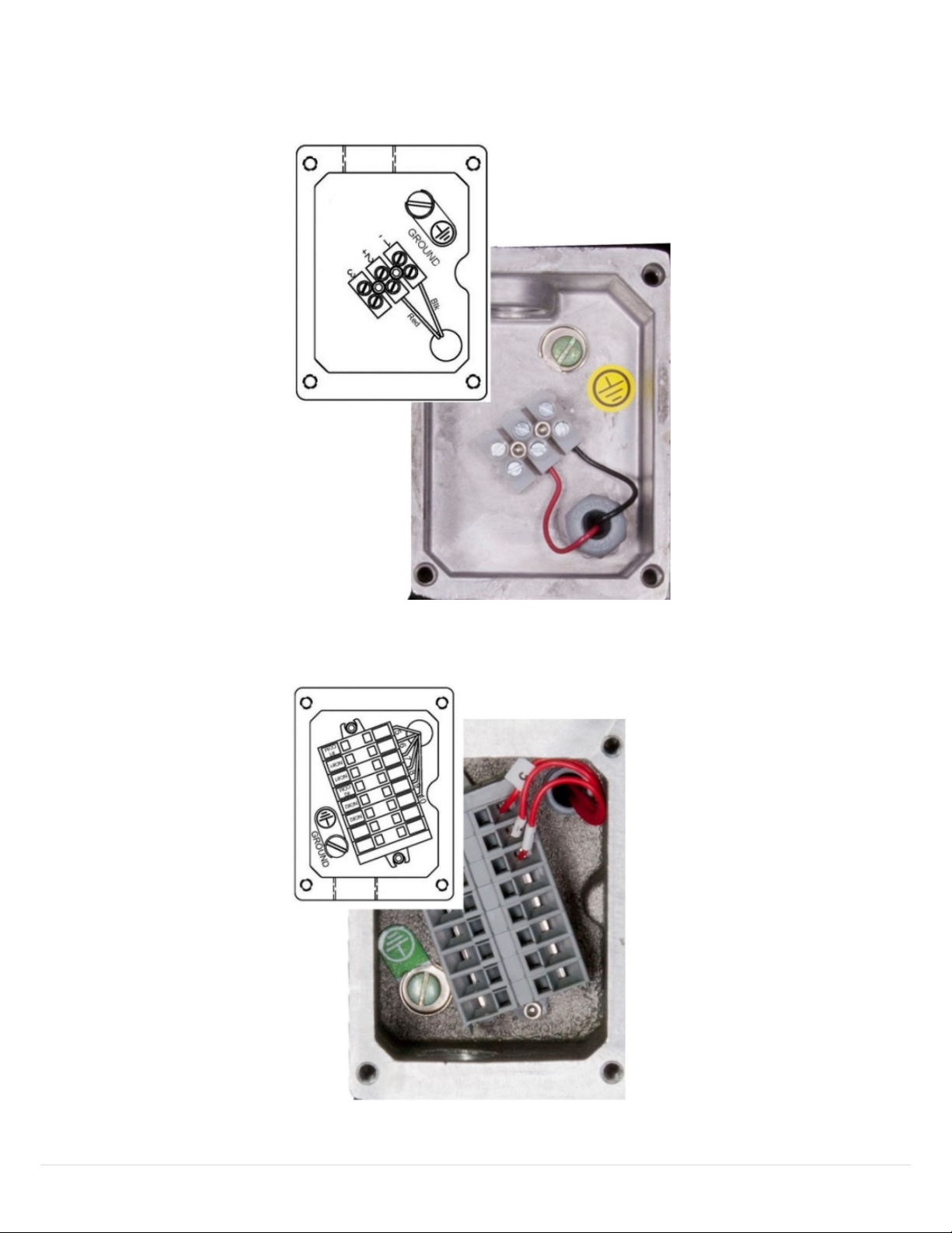
Figure 26: Transmitter Wiring with or without HART
Figure 27: Mechanical (Optional) Switch Wiring
32 | UFM
Page 33
5.2 Installation
Manufacturer Name:
Universal Flow
Model Name(s):
ME Transmitter
Manufacture ID Code:
24692
(6074 Hex)
Device Type Code:
230
(E1EF Hex)
HART Protocol Revision
7.0
Device Revision:
1
Number of Device Variables
4
Physical Layers Supported
FSK
Physical Device Category
Transmitter, Non-DC-isolated Bus Device
For best results, the meters may be installed in any position as long as proper piping installation requirements are
observed. This includes sufficient support of adjacent piping to minimize the system’s inherent vibration. Unions of
the same pipe size and full port isolation ball valves may be installed for ease of removal and servicing of
equipment, if necessary.
5.3 Device Identification
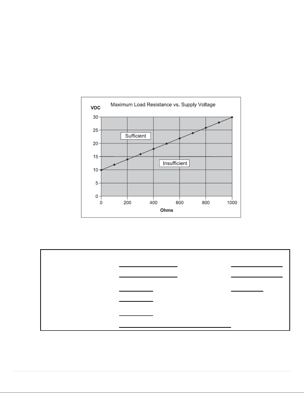
Figure 28: Maximum Load Resistance vs. Supply Voltage
Figure 29: Device Identification
33 | UFM
Page 34
5.4 Product Overview
The ME Transmitter is a two-wire loop-powered flow transmitter, with a 4-to-20mA output. This transmitter
uses a non-contact magnetic encoder for measuring the displacement of the shaft/pointer on standard
UFM flowmeters. It is an add-on feature to SN/SM/SH,MN/MM/MH,LL/LP/LH,LN/LE and XHF model flow
meters as manufactured by Universal Flow Monitors, Inc. The ME Transmitter replaces the earlier models
Digital Transmitters that utilized a potentiometer, providing improved accuracy while maintaining 100%
compatibility. The analog output of this device is linear with flow over the working range of all supported
flowmeters.
5.5 Process Interface
5.5.1 Magnetic Sensors
There are two built-in hall-effect sensors measuring the rotation of a permanent magnet that is
mounted onto the flowmeter shaft. As the shaft rotates with flow, the sensors provide analog
readings that are in turn converted to a digital value by and A/D converter. The digital values are
then processed by the microcontroller and linearized, and subsequently converted to a scaled
analog output via a D/A converter in the range of 4 to 20 mA.
5.5.2 Host Interface: Process Flow
The two-wire 4-20mA current loop is connected to two terminals on the transmitter circuit board. Depending
on the product used, one of the two configurations are offered for field wiring.
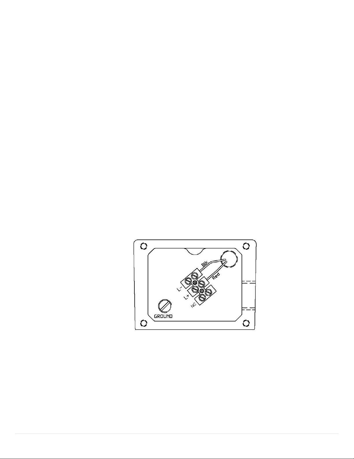
A secondary terminal strip away from the PCB (mounted in a separate compartment of the flowmeter) and is
marked L+ and L-. The red wire connects the (+) terminal on the PCB to L+ and the black wire connects the (–)
terminal on the PCB to L-.
Figure 30: PCB Wiring
This is the only output from this transmitter, representing the process flow measurement, linearized and
scaled according to the configured range of the instrument. This output corresponds to the Primary Variable.
HART Communication is supported on this loop.
34 | UFM
Page 35

A guaranteed linear over-range is provided. The up-scale current of 24mA can indicate device malfunction.
Direction
Values (percent of range)
Values (mA or V)
Linear over-range
Down
0% ± 0.5%
3.92 to 4.08 mA
Up
+106.25% ± 0.1%
20.84 mA to 21.16 mA
Device malfunction
indication
Down
N/A
N/A
Up
+125.0% ± 0.1%
23.98 mA to 24.02 mA
Maximum current
+106.25% ± 1%
20.84 mA to 21.16 mA
Multi-Drop current draw
4.0 mA
Lift-off voltage
10.5 V
Bit Mask
Definition
Conditions to set bit
0x80(bit 7)
Device Malfunction
None
0x40(bit 6)
Configuration Changed
Any change in device configuration
0x20(bit 5)
Cold start
Set any time power is cycled
0x10(bit 4)
More Status Available
Triggers when either alarm is active
0x08(bit 3)
Loop Current Fixed
None
0x04(bit 2)
Loop Current Saturated
Occurs when loop current reaches upper limit
0x02(bit 1)
Non-Primary Variable out of limits
None
0x01(bit 0)
Primary Variable Out of limits
Occurs when PV is being limited due to
exceeding calibrated limitations
Current values are shown in the table below.
5.1 Status Information
Table 26: Current Values table
Table 27: Device Status table
When Bit 4 is set, Host should send Command 48 to determine which alarm is active.
5.1.1 Extended Device Status
The Field Device cannot predict, in advance, when the maintenance will be required. Extended Device Status
is unused.
35 | UFM
Page 36

Table 28: Command 48-Byte Data
Byte
Description
Data
0-5
Device Specific Status
Only Byte 0 is used
6
Extended Device Status
Bit 1 will be set when an alarm condition is active.
7
Device Operating Mode
0
8
Standard Status 0
Not used
"Not used" bits are always set to 0.
Device does not support extended device status, all device status activity is included in the device status
byte.
5.2 Universal Commands
All Universal Commands are supported as specified in the HART Universal Command Specification.
5.3 Common-Practice Supported Commands
The following common-practice commands are implemented:
33 Read Device Variables
35 Write Range Values
42 Perform Master Reset
44 Write PV Units
54 Read Device Variable Information
In command 54 the acquisition period is unused. Values are typically updated every 100ms.
5.3.1 Burst Mode
This Field Device does not support Burst Mode.
5.3.2 Catch Device Variable
This Field Device does not support Catch Device Variable.
5.4 Device-Specific Commands
The following device-specific commands are implemented:
128 Read Alarm Setpoints
129 Write Low Alarm Setpoint
130 Write High Alarm Setpoint
131 Reset Totalizer
36 | UFM
Page 37
5.5 Command #129: Write Low Alarm Setpoint
Byte
Format
Description
0-3
Float
Low Alarm Setpoint
Byte
Format
Description
0
Enum
PV Unit value
1-4
Float
Low Alarm Setpoint
Code
Class
Description
0
Success
No Command-Specific Errors
1-15
Undefined
16
Error
Access Restricted
17-31
Undefined
32
Error
Busy
33-127
Undefined
Byte
Format
Description
None
Byte
Format
Description
None
Writes the Setpoint for the Low Alarm.
5.5.1 Request Data Bytes
Table 29: Request Data Bytes table
5.5.2 Response Data Bytes
Table 30: Response Data Bytes table
5.5.3 Command-Specific Response Codes
Table 31: Command-Specific Response Codes table
5.6 Command #131: Reset Totalizer
Resets the totalizer to zero.
5.6.1 Request Data Bytes
5.6.2 Response Data Bytes
Table 32: Request Data Bytes table
Table 33: Response Data Bytes table
37 | UFM
Page 38

5.6.3 Command-Specific Response Codes
Code
Class
Description
0
Success
No Command-Specific Errors
1-15
Undefined
16
Error
Access Restricted
17-31
Undefined
32
Error
Busy
33-127
Undefined
PV digital value calculation
10 per second
SV digital value calculation
10 per second
Analog output update
10 per second
Minimum
20ms
Typical
50ms
Maximum
100ms
Table 34: Command-Specific Response Codes table
5.7 Performance
5.7.1 Sampling Rates
Typical sampling rates are shown in the following table.
Table 35: Sampling Rates table
5.7.2 Power-Up
The device is typically ready within 1 second of power-up. Totalizer is initialized to zero.
5.7.3 Reset
Command 42 ("Device Reset") causes the device to reset its microcontroller. The resulting restart is
identical to the normal power up sequence. (See Section 5.7.2.)
5.7.4 Self-Test
Self-Test is not supported.
5.7.5 Command Response Times
Table 36: Command Response Times table
38 | UFM
Page 39

5.8 Annex A: Capability Checklist
Manufacturer, model and revision
Universal Flow, ME Transmitter, Rev1
Device type
Transmitter
HART revision
7.0
Device Description available
No
Number and type of sensors
2 internal
Number and type of actuators
0
Number and type of host side signals
1: 4 - 20mA analog
Number of Device Variables
4
Number of Dynamic Variables
2
Mappable Dynamic Variables?
No
Number of common-practice commands
5
Number of device-specific commands
4
Bits of additional device status
2
Alternative operating modes?
No
Burst mode?
No
Write-protection?
No
Table 37: Capability Checklist table
39 | UFM
Page 40
6 Vane/Piston TX/TXL
Installation and Operation Manual Series: LL, LP, LH, PI, SN, SM, SH, MN, MM, MH, SX and MX
6.1 Nameplates and Product ID
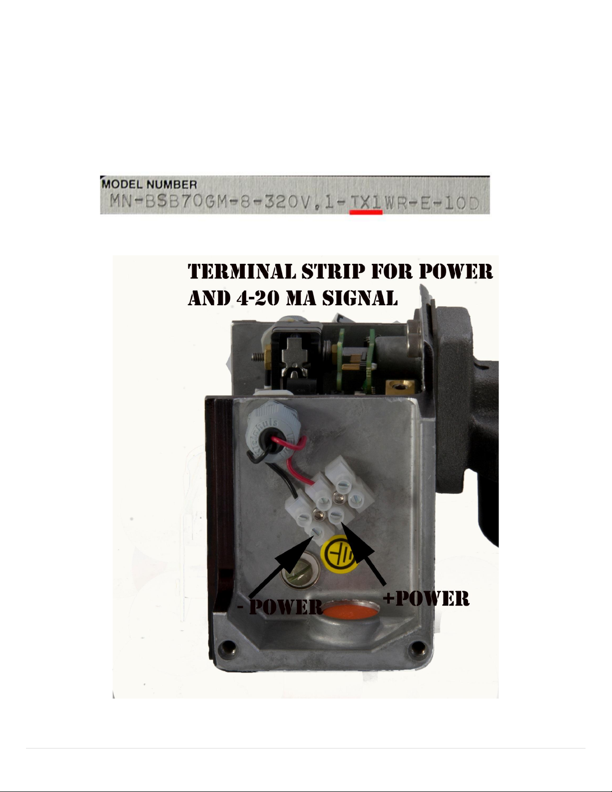
This manual applies to all vane/piston meters that have the designator “TX0,1,2,3,4 or 61” or “TXL0,1,3,
61” in the model code. This can be seen on the name plate as shown below.
Figure 31: Nameplates and Product ID
Figure 32: Terminal Strip for Power and 4-20 mA Signal
40 | UFM
Page 41
PIPING:
Screw pipe into meter with flow going into port marked “IN”. Teflon tape or pipe dope
discouraged.
WIRING:
Connect switch wires (for TX1,3 and 61 units) and/or open collector alarm and transmitter
wires to the terminal strip as shown.
Wire must be in accordance with all local and national codes. Wire size and insulation ratings
should support actual loads. In all cases, wire must be, as a minimum, 20 AWG Teflon insulated
rated at 600 V and 200 ˚C. It is recommended to include a disconnect switch or circuit breaker
near this equipment.
CÂBLAGE
Le câble doit être conforme à tous les codes locaux et nationaux. Le diamètre du câble et ses
niveaux d’isolation doivent pouvoir supporter des charges réelles. Dans tous les cas, le câble
doit être isolé au minimum en téflon de calibre 20 AWG et d’une capacité nominale de 600 V et
de 200°C. Il est recommandé d’inclure un interrupteur général ou un disjoncteur à proximité de
cet équipement.
GROUNDING:
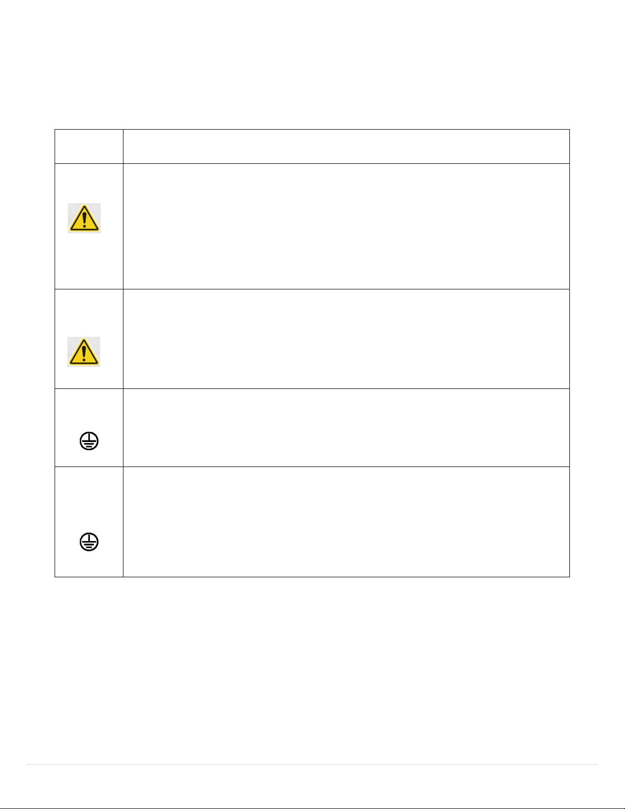
For protection against electrical shock in case of a fault, connect an external earth ground to
the grounding screws or lugs provided inside this instrument. Such attachment points are
identified with a tag or label adjacent to the grounding screw or lug with the symbol.
MISE À LA
TERRE
Pour se protéger des chocs électriques en cas de défaut à la terre, brancher une mise à la terre
externe sur les vis ou cosses de mise à la terre fournies à l’intérieur de cet instrument. De tels
points de fixation sont identifiés à l’aide d’une étiquette ou d’un label adjacent à la vis ou à la
cosse de mise à la terre avec le symbole.
41 | UFM
Page 42
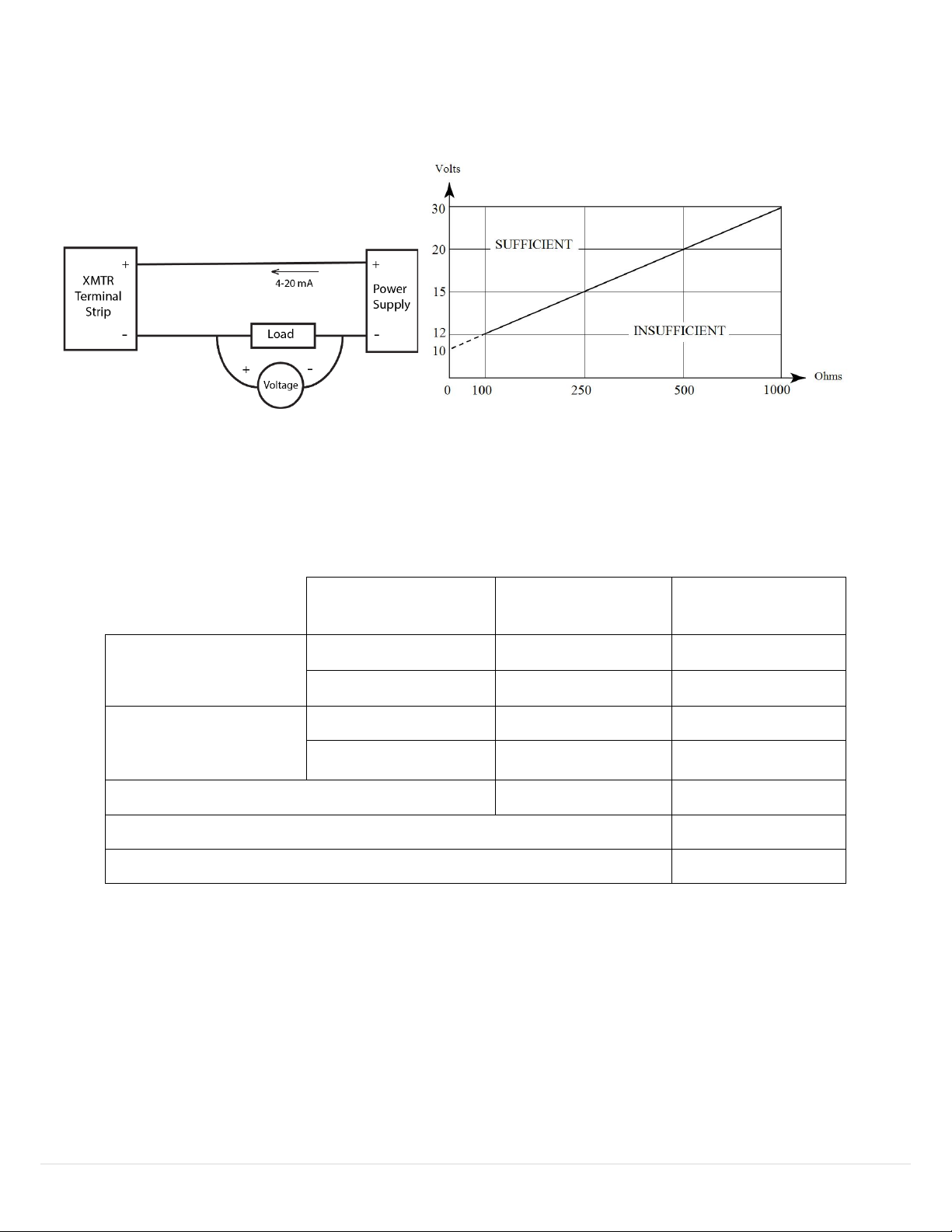
Load Resistor vs. Power Supply
A typical 4-20mA wiring diagram is shown below:
Direction
Values (percent of
range)
Values (mA or V)
Linear over-range
Down
0% ± 0.5%
3.92 to 4.08 mA
Up
+106.25% ± 0.1%
20.84 mA to 21.16 mA
Device malfunction
indication
Down
N/A
N/A
Up
+125.0% ± 0.1%
23.98 mA to 24.02 mA
Maximum current
+106.25% ± 1%
20.84 mA to 21.16 mA
Multi-Drop current draw
4.0 mA
Lift-off voltage
10.5 V
Figure 33: 4-20 mA Wiring Diagram and Load Resistor vs. Power Supply diagram
A guaranteed linear over-range is provided. Device malfunction can be indicated by the up-scale current of 24mA. Current
values are shown in the table below.
Table 38: Current Values table
42 | UFM
Page 43
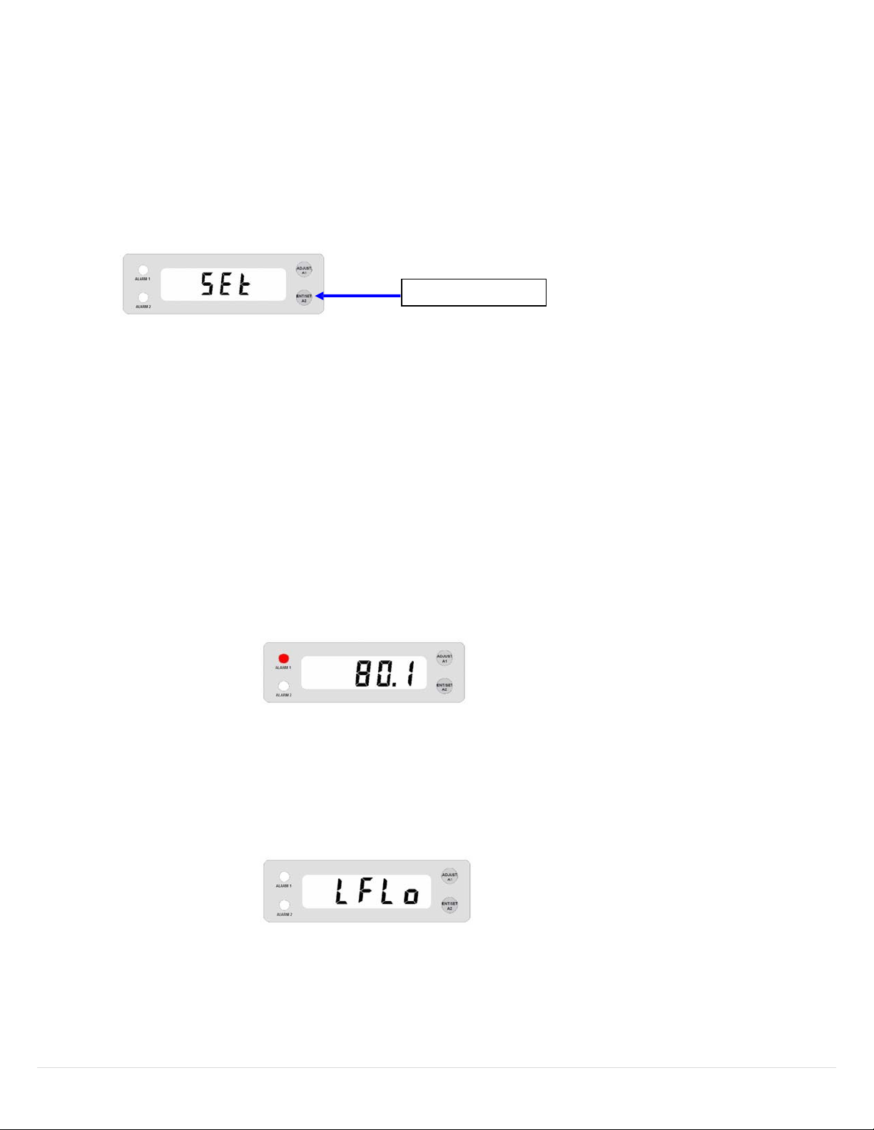
Figure 36: Set Low Flow Alarm
1. After the last digit is set, continue holding A2 until “SEt” is displayed. If you want to change
Release
Figure 34: press and release A2
Figure 35: LED activation example
the first digit again, do not hold A2. Momentarily press and release A2 and the first digit starts
blinking again.
2. Wh
en finished recording the new setpoint (“SEt” is displayed), release A2.
Note 1: Valid setpoint range is 0-100% of full-scale flow. If the alarm value is set higher than fullscale, it is clamped at full-scale upon exiting this menu.
Note 2: To disable the alarm, set its value to zero.
Note 3: The red ALARM 1 LED comes on when flow exceeds this setpoint. This LED is in series with the
drive circuit for the high-alarm open-collector output, meaning that the output transistor is active whenever
this LED is on. Some models do not have any external wiring that connects to the alarm transistor (see
Model Codes).
In this example, the high alarm had been set for 80.0; therefore, the red LED was activated when flow
reached 80.1.
The LED turns off when flow < (setpoint – hysteresis). Hysteresis is 5% of full-scale.
6.2 Set Low Flow Alarm
1. Press A2 until “LFLo” is displayed, then release A2.
43 | UFM
Page 44

Improving the world, one measurement at a time.
TM
dwyeromega.com
 Loading...