

Page 1

Page 2

EC Declaration of Conformity
Counter / Timer BoardsCIO-CTR10HD&20HD
DescriptionPart Number
to which this declaration relates, meets the essential requirements, is in conformity
with, and CE marking has been applied according to the relevant EC Directives listed
below using the relevant section of the following EC standards and other normative
documents:
EU EMC Directive 89/336/EEC: Essential requirements relating to electromagnetic
compatibility.
EU 55022 Class B: Limits and methods of measurements of radio interference
characteristics of information technology equipment.
EN 50082-1: EC generic immunity requirements.
IEC 801-2: Electrostatic discharge requirements for industrial process measurement
and control equipment.
IEC 801-3: Radiated electromagnetic field requirements for industrial process
measurements and control equipment.
QUICK START
........................................
...........................
TM
..............................
DETAILED INSTALLATION
..............................
...................................
..........................
............................
I/O CONNECTOR & PINOUT
SOFTWARE
CIO-CTR ARCHITECTURE
..........................................
..............................
...............................
.................................
SPECIFICATIONS
.....................................
............................
....................................
................................
................................
ELECTRONICS AND INTERFACING
..............................
............
........................
.......................
...............
1
1 INSTALLING INSTACALTM
2 RUNNING INSTACAL
4
4 BASE ADDRESS
5 INTERRUPT LEVEL SELECT
5 CLOCK SOURCE SELECT
5 INSTALLING THE CIO-CTR IN THE COMPUTER
6
7
8
8 CONTROL & DATA REGISTERS
10 BASE +400 & +401
11
11 POWER CONSUMPTION
11 COUNTER I/O
11 INTERRUPT INPUT
11 ENVIRONMENTAL
12
12 VOLTAGE DIVIDERS
13 LOW PASS FILTERS DE-BOUNCE INPUTS
IEC 801-4: Electrically fast transients for industrial process measurement and control
equipment.
Carl Haapaoja, Director of Quality Assurance
Page 3
QUICK START
The CIO-CTR10HD and CIO-CTR20HD are easy to use. Here is the quick start procedure for those who know how to open the PC and install expansion boards, and
want to dive right in. The CIO-CTR20HD is really a single board with two CIOCTR10HD's on it. For the balance of this manual we will refer to both boards as the
CIO-CTRHD, and will only use the complete board name in instances where there are
items specific to one board or the other.
This quick start procedure will help you quickly and easily setup, install and test your
board. We assume you already know how to open the PC and install expansion
boards. If you are unfamiliar or uncomfortable with board installation, please refer to
your computer’s do cumentation. Tho ugh we recommend the use of InstaCal to guide
you through your installation, detailed written instructions are provided in the next
chapter.
We recommend you perform the software installation described in
sections below prior to installing the board in your computer. The
InstaC
switches and jumpers on the board prior to physically installing the
board in your computer.
TM
operations below will show you how to properly set the
al
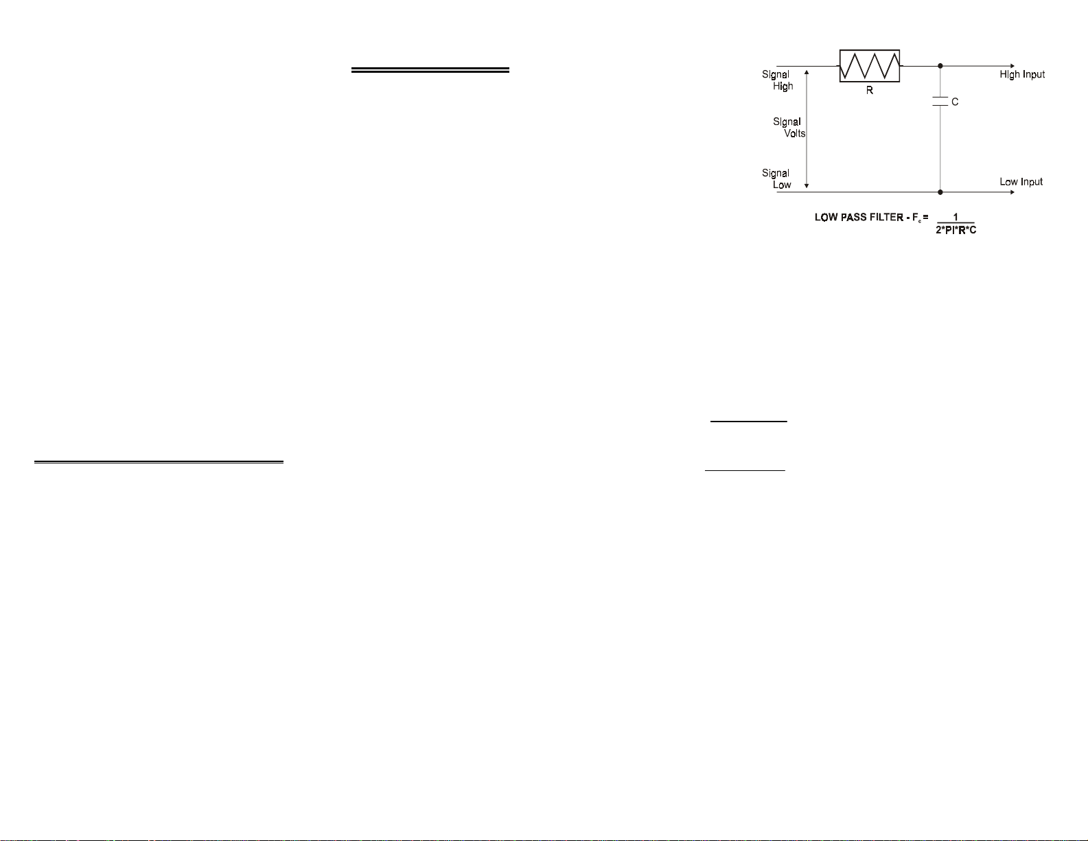
The key term in a low pass
filter circuit is
quency
. The cut off fre-
cut off fre-
quency is that frequency
above which no variation of
voltage with respect to time
may enter the circuit. For
example, if a low pass filter
had a cut off frequency of 30
Hz, the kind of interference
associated with line voltage
(60Hz) would be filtered out
but a signal of 25Hz would
be allowed to pass.
Also, in a digital circuit, a low pass filter might be used to de-bounce an input from a
momentary contact button pushed by a person.
A low pass filter may be constructed from one resistor (R) and one capacitor (C). The
cut off frequency is determined according to the formula:
Where Pi = 3.14...
Fc = 1
2 * Pi * R * C
INSTALLING INSTACALTM
Windows (in its various forms) and DOS users install the program by running the
INSTALL.EXE program supplied on your InstaCal diskette (some releases of InstaCal
will provide SETUP.EXE rather than Install.EXE. Use SETUP.EXE if it is included
on your InstaCal disk). It will create all required folders/directories and unpack the
various pieces of compressed software. Simply run install/setup and follow the onscreen instructions. Note where the installed files are placed, as you will need to
access them in the next step (the default location is on your main hard drive in a directory or folder named C:\CB\).
1
R = 1
2 * Pi * C * F
c
14
Page 4

2 = 10K + 10K
10K
R1 = (A - 1) * R2
For example, if the signal varies between 0
and 20 volts and you wish to measure that
with an input with a full scale range of 0 to 10
volts, the Attenuation is 2:1 or just 2.
For a given attenuation, pick a handy resistor
and call it R2, then use this formula to calculate R1.
RUNNING INSTACAL
TM
To run InstaCalTM in the various forms of Windows, find the file named InstaCal.exe
using your file management system and do ub le cli ck your mouse on i t. In DO S simply
type instacal and press the Enter key.
Once running, InstaCal
TM
provides four sub-menus (plus exit).
Digital inputs also make use of voltage dividers, for example, if you wish to measure a
digital signal that is at 0 volts when off and 24 volts when on, you cannot connect that
directly to the CIO-CTR digital inputs. The voltage must be dropped to 5 volts max
when on. The Attenuation is 24:5 or 4.8. Use the equation above to find an appropriate R1 if R2 is 1K. Remember that a TTL input is 'on' when the input voltage is
greater than 2.5 volts.
IMPORTANT NOTE
The resistors, R1 and R2, are going to dissipate all the power in the
divider circuit according to the equation Current = Voltage / Resistance. The higher the value of the resistance (R1 + R2) the less
power dissipated by the divider circuit. Here is a simple rule:
For Attenuation of 5:1 or less, no resistor should be less than
10K.
For Attenuation of greater than 5:1, no resistor should be less than
1K.
The CIO-TERMINAL has the circuitry on board to create custom voltage dividers.
The CIO-TERMINAL is a 16" by 4" screw terminal board with two 37 pin D type
connectors and 56 screw terminals (12 - 22 AWG). Designed for table top, wall or
rack mounting, the board provides prototype, divider circuit, filter circuit and pull-up
resistor positions which you may complete with the proper value components for your
application.
1. Select Install (either highlight it and hit enter or double click your mouse on it).
2. Select Board #0 (select another number if Board #0 is already installed)
3. Select Board Type
4. Move through the sele ctions and highlight the particular bo ard you are installing
(e.g. CIO-CTR10HD or CIO-CTR20HD). Double click on the board or hit enter.
5. The board’s default settings are then displayed. The board’s defaults are:
BASE ADDRESS: 300H (768 Decimal) Same as data sheet. If
address 300 is not available, choose another and
InstaCal will show you the correct switch setting.
WAIT STATE: OFF.
6. You are now ready to install the board in your computer. Turn off your computer,
unplug it from AC power, o pen your PC and i nstall the boar d in any unused ISA
slot. After the board is installed and the computer is closed up, turn the power
back on.
7. Run InstaCal
TM
again, and at the main menu select Test.
a. Select the board you just installed
b. Select Internal Test
LOW PASS FILTERS DE-BOUNCE INPUTS
A low pass filter is placed on the signal wires between a signal and an A/D board. It
stops frequencies greater than the cut off frequency from entering the A/D board's
analog or digital inputs.
13
c. The internal control registers of the board will then be tested. If this test
is successful, your board is installed correctly. If not, you likely have
a base address conflict, or have the base address switch set incorrectly.
Please refer to the next chapter for more information regarding selecting
and setting the base address.
d. If the Internal Test is completed successfully, you may want to check
that the I/O pins are working correctly. To check this select
External Test and follow the instruction provided. This will
2
Page 5
require you to use the shorting wires supplied with the board to
short inputs to outputs for I/O testing.
ELECTRONICS AND INTERFACING
VOLTAGE DIVIDERS
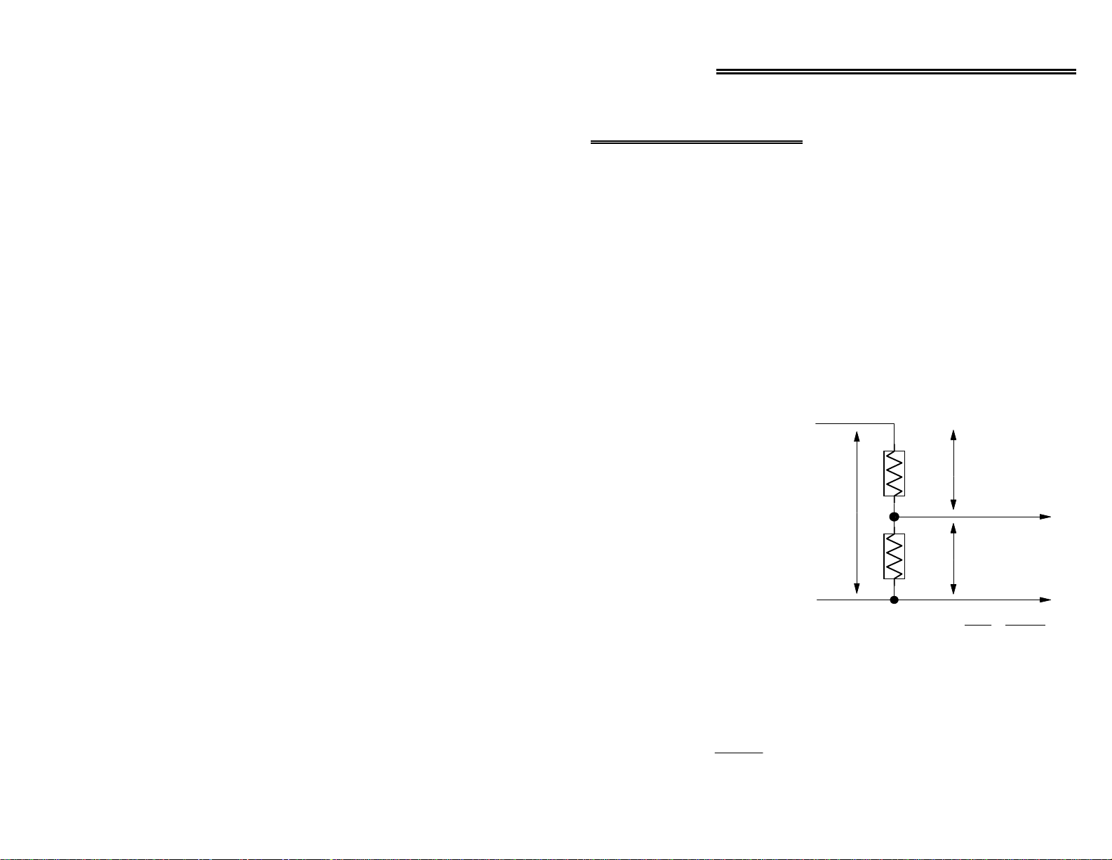
If you wish to measure a signal which varies over a range greater than the input range
of a digital input, a voltage divider can drop the voltage of the input signal to the level
the digital input can measure.
A voltage divider takes advantage of Ohm's law, which states,
Voltage = Current * Resistance
and Kirkoff's voltage law which states,
The sum of the voltage drops around a circuit will be equal to the
voltage drop for the entire circuit.
Implied in the above is that any
variation in the voltage drop for
the circuit as a whole will have a
proportional variation in all the
SIGNAL
HIGH
R1 V1
voltage drops in the circuit.
A voltage divide r takes ad vantage
of the fact that the voltage across
one of the resistors in a circuit is
proportional to the voltage across
the total resistance in the circuit.
The trick to using a voltage
divider is to choose two resistors
SIGNAL
VOLTS
SIGNAL
LOW
SIMPLE VOLTAGE DIVIDER
V in
R2
-
V2
V out
V in
V out
HIGH INPUT
LOW INPUT
R1 + R2
=
R2
with the proper proportions relative to the full scale of the digital input and the maximum signal voltage.
The phenomena of dropping the voltage proportionally is often called attenuation.
The formula for attenuation is:
Attenuation = R1 + R2
R2
The varaiable Attenuation is the proportional
difference between the signal voltage max and
the full scale of the input.
3
12
Page 6
POWER CONSUMPTION
SPECIFICATIONS
DETAILED INSTALLATION
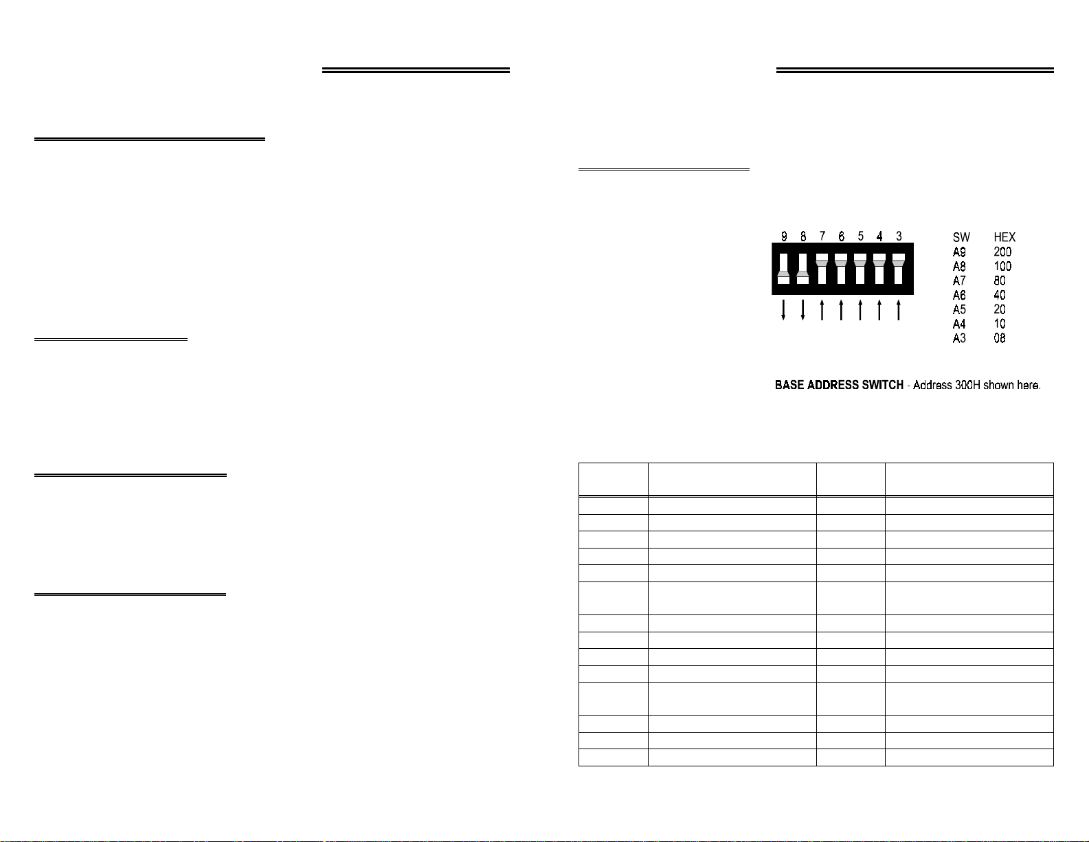
The CIO-CTRHD has o ne bank of switches, a base addr ess switch which must be set
before installing the board in your computer. The InstaCal program included with the
CIO-CTR will show how these switches are to be set and may be run before you
install the board, or you may proceed from the information here.
+5V Supply
Additional power will be drawn by user's connections to the power
pins accessible on CIO-CTR connectors.
COUNTER I/O
INTERRUPT INPUT
ENVIRONMENTAL
10HD: 475mA typical, 590mA max
20HD: 825mA typical, 1AMP max
None+12V Supply
None-12V Supply
NOTE
0.4 V Max @ 3.2 mA9513 Output Low
2.4 V Min @ -200 uA9513 Output High
-0.5V Min, 0.8V Max9513 Input Low
2.2V Min, +5VMax9513 Input High
Positive Edge TriggeredType
IRQ2 - IRQ7PC Bus IRQ
Base +400Enable
0 - 50 Deg COperating Temperature
-20 to 70 Deg CStorage Temperature
0 to 90% Non-CondensingHumidity
5 Oz.Weight
BASE ADDRESS
Unless there is already a
board in your system which
uses address 300 HEX (768
Decimal) then you can leave
the switches as they are set at
the factory.
In the example shown here,
the CIO-CTR is set for base
address 300H (768 Decimal).
Certain address are used by
the PC, others are free and may be used by the CIO-CTRHD and other expansion
boards. We recommend BASE = 300H (768D) be tried first.
FUNCTIONHEX
EGA2C0-2CF8237 DMA #1000-00F
EGA2D0-2DF8259 PIC #1020-021
GPIB (AT)2E0-2E78253 TIMER040-043
SERIAL PORT2E8-2EF8255 PPI (XT)060-063
SERIAL PORT2F8-2FF8742 CONTROLLER (AT)060-064
PROTOTYPE CARD300-30FCMOS RAM & NMI
PROTOTYPE CARD310-31FDMA PAGE REGISTERS080-08F
HARD DISK (XT)320-31F8259 PIC #2 (AT)0A0-0AF
PARALLEL PRINTER378-37FNMI MASK (XT)0A0-0A1
SDLC380-38F8237 #2 (AT)0C0-0DF
SDLC3A0-3AF80287 NUMERIC CO-P
MDA3B0-3BBHARD DISK (AT)1F0-1FF
PARALLEL PRINTER3BC-3BFGAME CONTROL200-20F
EGA3C0-3CFEXPANSION UNIT (XT)210-21F
RANGE
070-071
0F0-0FF
FUNCTIONHEX
RANGE
MASK (AT)
(AT)
11
4
Page 7
RANGE
FUNCTIONHEX
RANGE
FUNCTIONHEX
BASE +400 & +401
SERIAL PORT3E8-3EFALT BUS MOUSE23C-23F
FLOPPY DISK3F0-3F7PARALLEL PRINTER270-27F
SERIAL PORT3F8-3FFEGA2B0-2BF
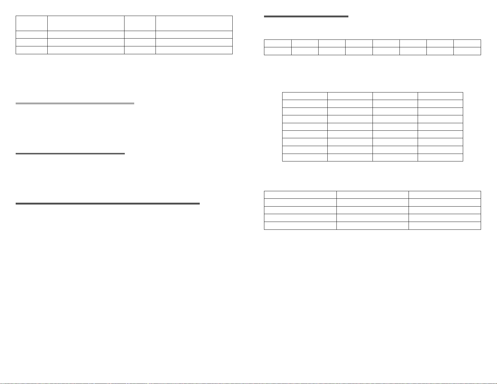
D0D1D2D3D4D5D6D7
L0L1L2CLK00CLK01CLK10CLK11WSEN
The CIO-CTRHD BASE switch may be set for address in the range of 000-3F8 so it
should not be hard to find a free address area for your CIO-CTRHD. Once again, if
you are not using IBM prototyping cards or some other board which occupies these
addresses, then 300-31F HEX are free to use. Address not specifically listed, such as
390-39F, are usually free.
INTERRUPT LEVEL SELECT
A single interrupt input at pin 26 allows you to initiate an interrupt service routine
with an external pulse. The interrupt level is selected via software and is one of the
options set in the InstaCal configuration file.
CLOCK SOURCE SELECT
The source of the pulses supplied to the 9513 for timing operations is programmable
and there are a number of options. These options are shown in the InstaCal INSTALL
screen.
INSTALLING THE CIO-CTR IN THE COMPUTER
Turn the power off. Remove the cover of your computer. Please be careful not to dislodge any of the cables installed in your computer as you slide the cover off.
Locate an empty expansion slot in your computer.
Read - No read function for this register.
Write - L0, L1, and L2 select IRQ as follows:
IRQL0L1L2
N/A000
N/A100
2010
3110
4001
5101
6011
7111
CLK0# selects the clock cource for the 9513 designated “U1.” CLK1# selects the
clock source for the 9513 designated “U2.”
CLOCK SOURCECLK#0CLK#1
1 MHz00
5 MHz10
External01
N/A11
WSEN enables or disables the wait state.
1 = Wait State Enabled
0 = Wait State Disabled
Push the board firmly down into the expansion bus connector. If it is not seated fully
it may fail to work and could short circuit the PC bus power onto a PC bus signal.
This could damage the motherboard in your PC as well as the CIO-CTRHD.
The CIO-CTRxxHD connector is a 50 pin header type connector. All the signals from
the 9513 and interrupt are accessible. Pin one is designed by a square solder pad. It is
the pin on the PC Bus end of the connector, and closest to the edge of the card.
Cables C50FF-2 and the CIO-MINI50 allow easy connection to all of the counter signals through 12 -22 AWG sc rew terminals. T he CIO-CT R20H D has two of these co nnectors, P1 and P2. The signals on each are identical.
5
NOTE: Base +400 applies to CTR10HD and the first ten channels
of CTR20 HD. Base +401 applies to CTR20HD only and the second ten channels.
10
Page 8
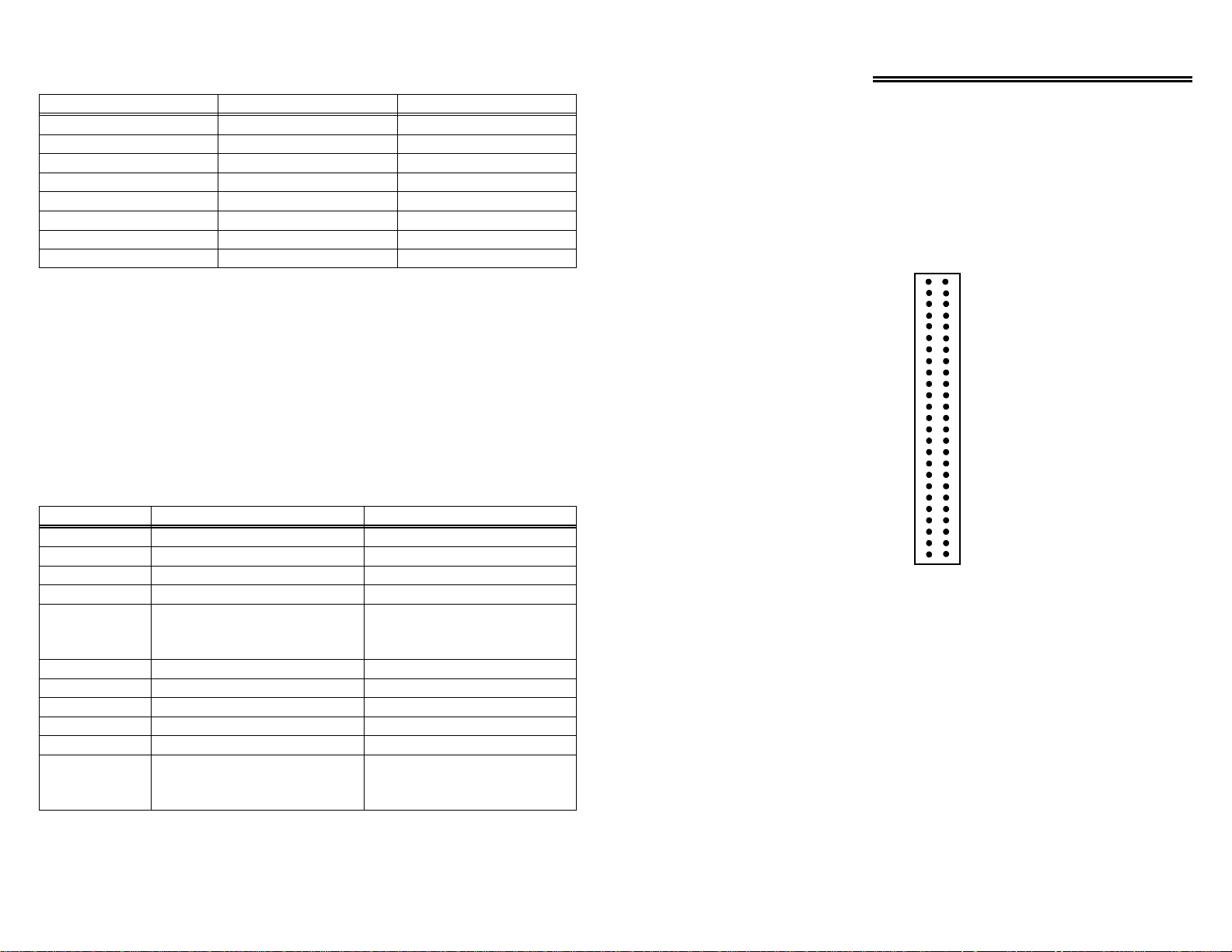
To write to or read from a register in decimal or HEX, the following weights apply:
HEX VALUEDECIMAL VALUEBIT POSITION
110
221
442
883
10164
20325
40646
801287
To write control or data to a register, the individual bits must be set to 0 or 1 then
combined to form a Byte. Data read from registers must be analyzed to determine
which bits are on or off.
The method of programming required to set/read bits from bytes is beyond the scope
of this manual. It will be covered in most Introduction To Programming books, available from a bookstore.
In summary form, the registers and their function are listed on the following table.
Within each register are 8 bits which may constitute a byte of data or 8 individual bit
functions.
WRITE FUNCTIONREAD FUNCTIONADDRESS
Data for 9513 #1Data from 9513 #1BASE +0
Commands to 9513 #1Status of 9513 #1BASE +1
Data for 9513 #2Data from 9513 #2BASE +2
Commands to 9513 #2Status of 9513 #2BASE +3
No read function.BASE +400
Wait State, Interrupt and
Counter Source (1st ten channels)
CTR20 only
Data for 9513 #3Data from 9513 #3BASE +4
Commands to 9513 #3Status of 9513 #3BASE +5
Data for 9513 #4Data from 9513 #4BASE +6
Commands to 9513 #4Status of 9513 #4BASE +7
No read function.BASE +401
Wait State, Interrupt and
Counter Source (2nd ten channels)
I/O CONNECTOR & PINOUT
The CIO-CTRxxHD use a 50-pin inline connector. The CIO-CTR10HD has only one
connector while the CIO-CTR20HD has two. The connectors are compatible with the
optional CFF50-series cables and CIO-MINI50 screw terminal adapter board. The
pinout of these connectors is shown below.
GND
50
FOUT
48
GND
46
CTR OUT 5
CTR OUT 4
CTR OUT 3
CTR OUT 2
CTR OUT 1
CTR OUT 5
CTR OUT 4
CTR OUT 3
CTR OUT 2
CTR OUT 1
44
GND
42
40
GND
38
36
GND
34
32
GND
30
28
IR INPUT
26
GND
24
FOUT
22
GND
20
18
16
GND
14
12
GND
10
8
GND
6
4
GND
2
CIO-CTRxxHD CONNECTOR
49
47
45
43
41
39
37
35
33
31
29
27
25
23
21
19
17
15
13
11
9
7
5
3
1
+5V
EXT SRC
GATE 5
CLK IN 5
GATE 4
CLK IN 4
GATE 3
CLK IN 3
GATE 2
CLK IN 2
GATE 1
CLK IN 1
+5 V
+5 V
EXT SRC
GATE 5
CLK IN 5
GATE 4
CLK IN 4
GATE 3
CLK IN 3
GATE 2
CLK IN 2
GATE 1
CLK IN 1
9
6
Page 9
SOFTWARE
CIO-CTR ARCHITECTURE
Each CIO-CTRHD boards is supp lied with the InstaCal installation, calibration and
test package. Use it to guide the installation procedure. InstaCAL installation is
described in chapter one (Quick Start).
The CIO-CTRHD family is fully supported by the powerful Universal Library package. Details regarding installation and usage of the Universal Library software can be
found in the Universal Library documentation. Please note that InstaCal also creates a
configuration file required for programmers who use the Universal Library programming libraries.
For those programmers writing drivers of their own, a complete register description
follows.
CONTROL & DATA REGISTERS
The CIO-CTR10HD is composed of two AM9513 counter timer chips, the CIOCTR20HD is composed of four. Each 9513 contains five counters of 16 bits each.
Associated with each counter are an input source, a count register, a load register, a
hold register, an output and a gate. The 9513 is extremely flexible and this flexibility
can make it a challenge to program the chip directly.
Unlike an Intel 8254 which has a single source, single gate and unique I/O address for
each counter, the 9513 is fully programmable and any counter may be internally connected to any gate and receive it's counts from a number of sources. In addition, each
counter does not have a unique I/O address. The 9513 takes only two address per
chip, one of which is a data path to the counter's load and hold registers.
There is no 9513 register information in this manual. Those wishing to know more
about the AM9513 and its programming should request the manual from our technical
support group. As of this writing there is no charge for the manual.
We strongly suggest that you use t he Univer sal Lib rar y, rather than re sort to p rogr amming the 9513 directly. It is difficult to program and because programming support is
available through the Universal Library, we cannot help with other 9513 programming
The CIO-CTR is an I/O mapped expansion board. The CIO-CTR20HD occupies 8
I/O addresses and the CIO-CTR10HD occupies 4 addresses.
The first address, or BASE ADDRESS, is determined by setting a bank of switches on
the board.
Most of the functions that this board is capable of performing can be acheived using
the Universal Library. Unless you have a good reason for direct register
manipulation, we suggest you use the Universal Library.
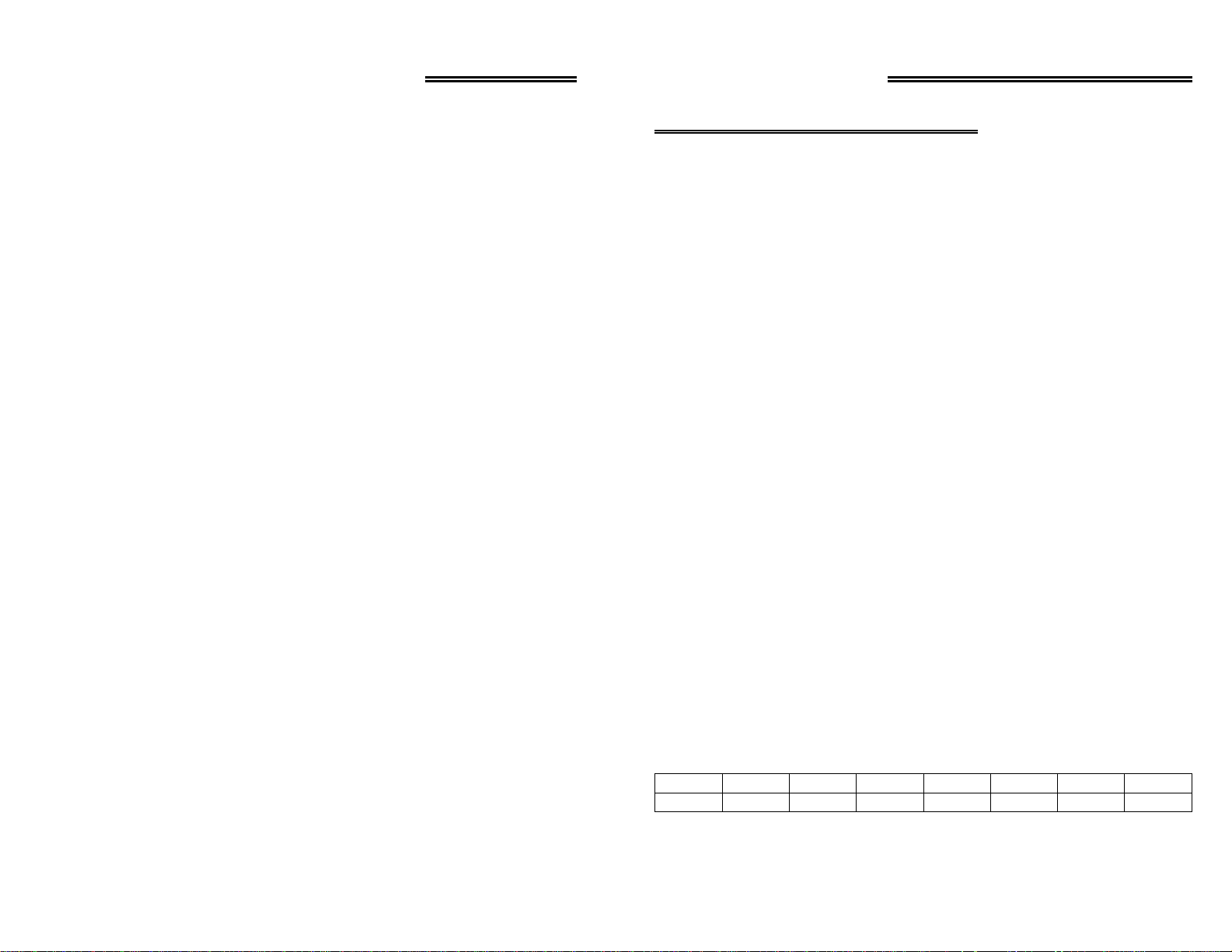
The register descriptions follow the format:
01234567
A0A1A2A3A4A5A6A7
Where the numbers along the top row are the bit positions within the 8 bit byte and the
numbers and symbols in the bottom row are the functions associated with that bit.
7
8
 Loading...