

Page 1
Band Heaters
DuraBand® with Built-In Strap
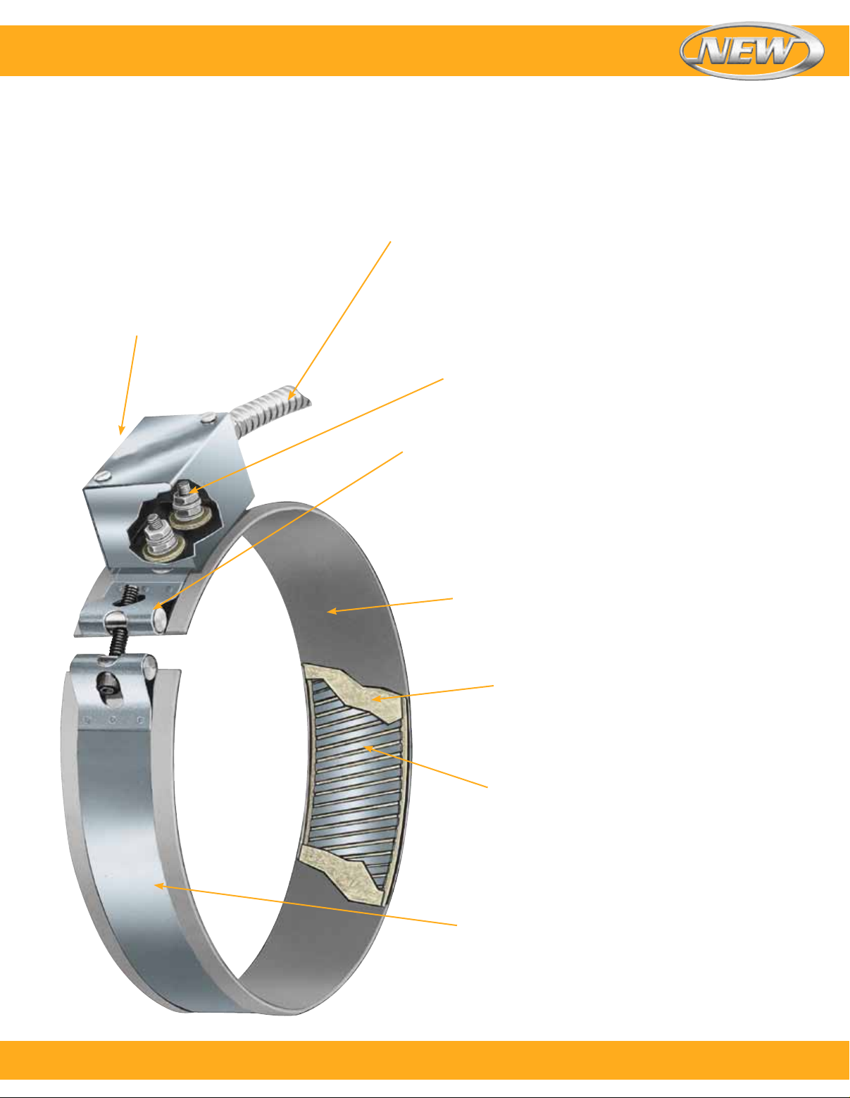
General purpose terminal box can be
attached on Duraband diameters of
63.5 mm (2¹⁄₂") or larger. It offers excellent
protection to exposed terminals. To
simplify wiring, the box has a 13 mm (¹⁄₂")
trade size knockout [actual diameter
22 mm (⁷⁄₈")] that will accept standard
conduit or flexible armor cable connectors.
It can be field assembled on most band
heaters with screw terminals having a
center distance of 22 mm (⁷⁄₈").
Flexible armor cable for lead
protection is available where
abrasion is a problem.
For maximum surface contact, the torque resistant and
virtually unbreakable stainless steel screw terminals are
securely fastened to a connecting jumper, assuring positive
contact with the windings and providing maximum amperage
carrying capacity. For other terminal or lead arrangements,
see pages 13 through 18.
Specially designed mounting brackets with ¹⁄₄"-20 socket cap
screws are used to draw the built-in strap to a high degree of
tension. This tension exerts the great amount of drawing power
required to pull the heating element assembly against the cylinder
evenly and tightly across its entire width, thus eliminating all air
gaps that can cause premature heater failure. The number of
bracket assemblies used increases as the width of a Duraband
heater increases.
Specially treated rust-resistant steel sheath casing
provides the best combination of physical strength,
high emissivity and good thermal conductivity to heated
cylindrical parts, good for sheath temperatures up to
480°C (900°F).
Specially selected grade and thickness of
mica sheet is used to insulate the windings,
providing excellent thermal conductivity and
dielectric strength.
The gauge of nickel-chrome resistance ribbon
wire is selected to achieve the lowest internal
element temperatures possible, resulting in
maximum heater life. The ribbon wire is wound
evenly spaced on a specially selected mica
strip, providing even heat distribution and
thus eliminating hot spotting that can cause
premature heater failure.
Duraband’s built-in strap is a unique design feature.
A low thermal expansion alloy sheath is used for
the outer sheath, covering the entire width of the
band heater.
To order, call 1-800-826-6342 or shop online at omega.com
SM
1
Page 2
Band Heaters
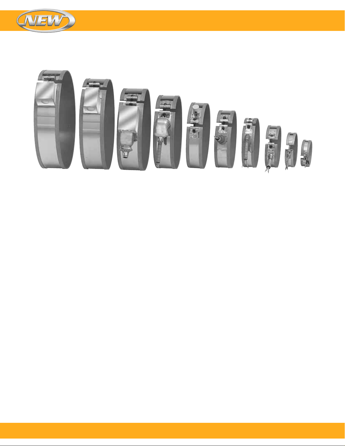
l Built-In Bracket for Superior Clamping
l Unbreakable and Torque-Resistant Screw Terminals
l Temperatures Up to 480°C (900°F)
l Full Width Stainless Steel Built-In Strap
l Flexibility to Incorporate Holes and Cutouts
l Available Two-Piece and Expandable Designs
l Best Mica Insulated Heater on the Market
l Faster Delivery than Any Other Type of Heater Band
l Most Economical Among Various Heater Bands
l Most Versatile and Commonly Used Heater Band
Typical Applications
l Plastic Injection Molding Machines
l Plastic Extruders
l Oil Reclamation Equipment
l Food and Candy Extruders
l Drum Heating
l Extrusion Dies
l Holding Tanks
l Blow Molding Machines
l Vending Machines
l Barrels and Heads
l Food Service Warming
l Autoclaves and Sterilizers
l Metallurgical Analyzers
l Fluidized Beds
l Hot Runner Molds
l Pulp and Paper Processing Equipment
Designed For Trouble-Free Service
The Duraband heater design is the result of many years
of research, development and testing for a reliable mica
insulated band heater that can perform at the higher
operating temperatures [up to 480°C (900°F)] essential to
process high temperature resins, providing long, efficient
service necessary for today’s high productivity of plastic
extruders, injection and blow molding machines.
Duraband is a proven heater design for good life efficiency
and dependability. It assures maintaining the lowest winding
temperatures possible, keeping a low-mass heating element
assembly for fast heat-up and quick thermal response to
controls. It incorporates the low thermal expansion
built-in strap, a unique design feature.
Advantages and Variations
Duraband mica insulated heaters are widely used on
operations involving heating of cylindrical surfaces and
are manufactured in a full range of standard construction
variations, physical dimensions, electrical ratings, and
a complete arrangement of screw terminals and lead
terminations. (See pages 13 through 18).
However, these standard Duraband heater variations
and terminations do not represent the full extent of our
capabilities. OMEGA’s engineering staff, with many years
of experience in heat processing and temperature control
applications, can assist you in designing the right Duraband
heater for your specific application.
2
To order, call 1-800-826-6342 or shop online at omega.com
SM
Page 3
Band Heaters
Standard Specifications and Tolerances
Performance Ratings
Maximum Temperature:
Standard Sheath: 482°C (900°F)
Nominal Watt Density: 3 to 7 Watt/cm
Maximum Watt Density: Dependent on heater size and
operating temperature
2
(20 to 45 Watt/in2)
Electrical Ratings
Maximum Voltage: 480 Vac
Dual Voltage or 3-Phase: Available depending on
heater design
Maximum Amperage:
Lead Wire Termination: 10 Amp
Screw Terminations: 8-32 UNF—20 Amp;
10-32 UNF—25 Amp
Resistance Tolerance: 10%, -5%
Wattage Tolerance: 5%, -10%
Minimum ID and Width for Construction/Clamping Styles
Physical Size Construction Limitations
Minimum Width: 19.1 mm (³⁄₄")
Width Tolerance: 1.59 mm (±¹⁄₁₆")
Minimum Inside Diameter: 22.1 mm (⁷⁄₈")
Nominal Gap: 9.5 mm (³⁄₈")—if a larger gap
is required for probes or thermocouples,
specify when ordering
Built-In Brackets
Heater Width Number of Brackets
38 to 76 mm (1¹⁄₂ to 3") 1
79 to 127 mm (3¹⁄₈ to 5") 2
130 to 145 mm (5¹⁄₈ to 6⁷⁄₈") 3
178 to 254 mm (7 to 10") 4
257 to 381 mm (10¹⁄₈ to 15") 5
If tighter tolerances are required, contact OMEGA.
CAUTION: Exposed electrical wiring on band
heater installations is a violation of Electrical
Safety Codes including O.S.H.A.
Minimum ID Minimum Width
Style mm inch mm inch
NB
NS
NE
SB
SS
SE
FB
FS
FE
SL
NSL
NEL
LT
LS
LE
TWL
RNB
RNS
Note: Refer to individual descriptions for further information. Actual heater minimums will be a combination of termination and
construction/strap styles.
50.8
76.2
63.5
22.1
50.8
63.5
25.4
50.8
63.5
101.6
101.6
101.6
177.8
177.8
177.8
25.4
134.7
254
2
3
2¹⁄₂
7/8
2
2¹⁄₂
1
2
2¹⁄₂
4
4
4
7
7
7
1
5¹⁄₂
10
31.8
31.8
31.8
19.1
19.1
31.8
19.1
19.1
31.8
31.8
31.8
31.8
38.1
38.1
38.1
25.4
25.4
25.4
1¹⁄₄
1¹⁄₄
1¹⁄₄
³⁄₄
³⁄₄
1¹⁄₄
³⁄₄
³⁄₄
1¹⁄₄
1¹⁄₄
1¹⁄₄
1¹⁄₄
1¹⁄₂
1¹⁄₂
1¹⁄₂
1
1
1
To order, call 1-800-826-6342 or shop online at omega.com
SM
3
Page 4
Maximum Watt Densities
Band Heaters
Watt Density — W/cm
Cylinder Temperature — °F
Watt Density — W/in
Correction Factors
For heaters wider than 76.2 mm (3"),
reduce maximum recommended watt
density from chart by 20%.
For applications using insulating shroud,
reduce maximum recommended watt
density from chart by 25%.
Calculating Maximum
Watt Density
Factors to be Taken into
Consideration:
A. Type of controls
B. Voltage variations
C. Machine cycling rate
D. Type of resin being processed
E. Coefficient of thermal expansion and
conductivity of the cylinder
F. Designing a heater that closely
matches the wattage requirement will
decrease the frequency of cycling
and temperature overshoot, thereby
increasing the life of the heater.
2
[3.14 × (Band ID) - Gap-1³⁄₈] × Band Width – Unheated Area (see table)
Watt Density (Watt/in
) =
2
2
Once These Factors have been
Established, Proceed with the
Following Steps:
1. Determine the maximum
operating temperature.
2. Calculate the total wattage required
to obtain the maximum operating
temperature.
3. Determine the quantity and size
of the heater bands to be used.
38 through 76 mm (1¹⁄₂ through 3")
wide band heaters have proven to be
the most efficient and reliable in most
cylindrical heating applications.
4. Determine individual band heater
wattage by dividing the total required
wattage by the quantity of band
heaters selected.
5. Determine the band heater watt
density by subtracting unheated
areas from the band heater
diameter created by screw
terminals, gaps, holes, and
cutouts (see formula below).
Watt Density Formula
Wattage
Maximum Allowable
Watt Density
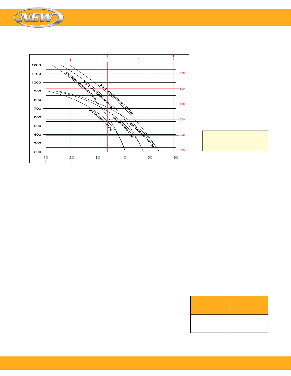
The chart displays the maximum
Cylinder Temperature — °C
Watt Density curves for various
diameter heaters. Use this chart
when determining the appropriate
wattage value for your chosen
heater.
Be aware that certain factors will
require you to derate the watt
density (Watt/in2) of your heater
selection.
CAUTION: Failure to adhere
to the maximum allowable watt
density per heater size will
result in poor operating life.
6. Determine if the required watt density
previously calculated exceeds
the maximum recommended watt
density. Note the maximum cylinder
temperature required on the left-hand
side of the graph, follow the horizontal
line until it intersects with the line of
the band heater being used, and read
directly down to obtain the maximum
recommended watt density (Watt/in2).
7. If the calculated watt density is higher
than the recommended value, it must
be corrected or it will cause poor
heater life. This can be accomplished
by using more band heaters,
lowering the heater wattage, or using
a different construction type or a
different type of band heater.
8. Should you have a problem in
selecting the proper band heater
or establishing watt density for
your application, contact one of the
qualified engineers at OMEGA.
Nominal Unheated Areas
Construction
Style
One-piece band
Two-piece band
Holes and cutouts
Unheated Area
to Subtract
1" × width
2" × width
Size + ¹⁄₂" × width
Unheated Area (See Table) = Unheated area for construction style + unheated area for any holes or cutouts
4
To order, call 1-800-826-6342 or shop online at omega.com
SM
Page 5
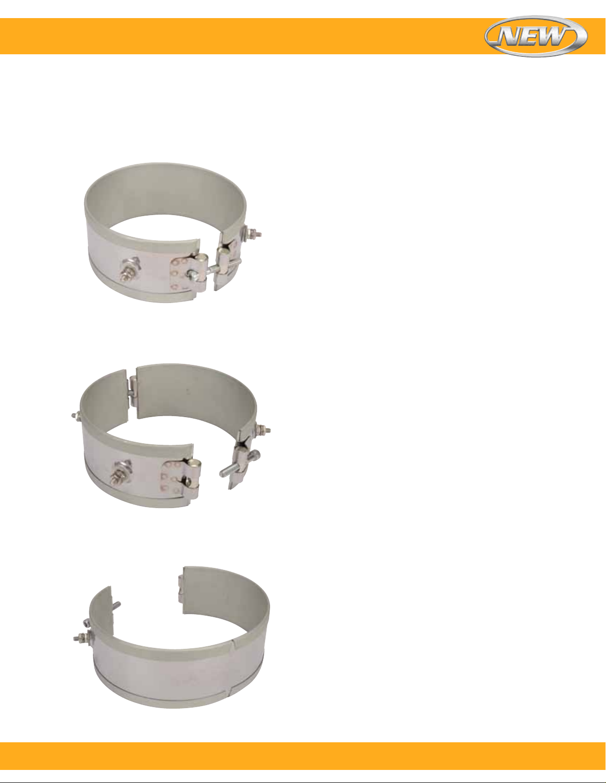
Band Heaters
Construction Styles
3 Construction Types
Shown with Type NB Built-In Strap
One-Piece Band
The one-piece construction is available on any screw or lead
termination and clamping variation. It can be used where
band heaters can be slipped over the end of the cylinder.
Shown with Type NS Built-In Strap
Two-Piece Band
The two-piece construction is available on any screw or lead
and clamping variation. The Duraband two-piece design
provides a built-in hinge, making handling and installation
easier. It is used on large cylinders or where the heater
cannot be slipped over the end of the cylinder. Two-piece
band heaters are rated at watts and volts per each half
when ordering.
Note: Multiple segment designs are recommended on larger
diameter [typically larger than 381 mm (15")] heaters to improve the
clamping force and increase the surface contact between the heater
and the barrel for efficient heat transfer.
One-Piece Expandable Band
The one-piece expandable construction is available on any
screw or lead and clamping variation. It can be used where a
one-piece band heater would have to be expanded to fit over
the barrel during installation, rather than slipped over the end
of the barrel.
Note: The one-piece expandable band should not be opened and
closed more than twice.
Shown with Type NE Built-In Strap
To order, call 1-800-826-6342 or shop online at omega.com
SM
5
Page 6
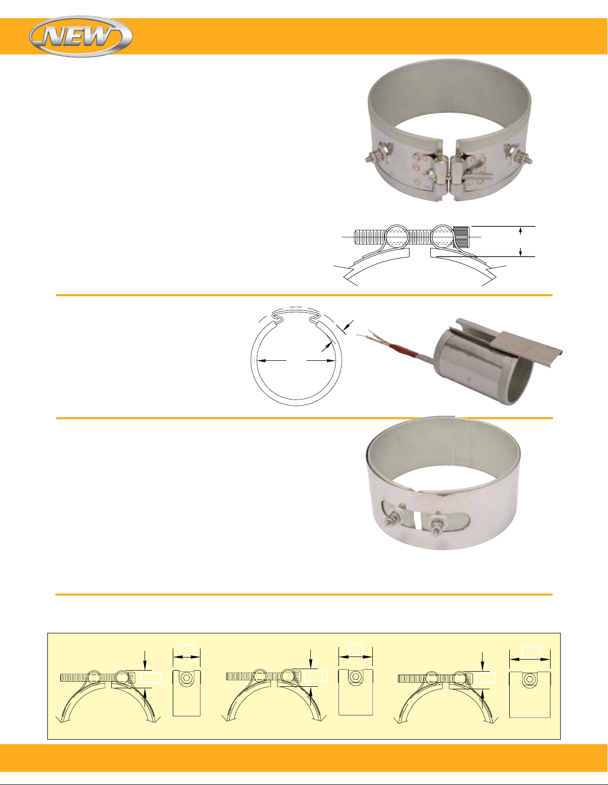
Construction/Clamping Variations
Standard Built-In Strap Clamping
(Low Thermal Expansion)
The built-in strap is available with any screw or lead
termination and construction variation. The built-in strap
eliminates the use of awkward-to-handle separate straps,
providing more drawing power than any other type of
clamping system. The Duraband with built-in strap is
standard on many designs.
Band Heaters
Type NB—One-Piece Band
Minimum ID: 50.8 mm (2")
Minimum Width: 31.8 mm (1¹⁄₄")
Type NS—Two-Piece Band
Minimum ID: 76.2 mm (3")
Minimum Width: 31.8 mm (1¹⁄₄")
Type NE—One-Piece Expandable Band
Minimum ID: 63.5 mm (2¹⁄₂")
Minimum Width: 31.8 mm (1¹⁄₄")
Wedge Lock
Wedge lock clamping is designed for applications
where mounting space is severely limited. It lends
itself mainly to small diameter nozzle heaters.
Type TWL—One-Piece Band
Minimum ID: 25.4 mm (1")
Minimum Width: 25.4 mm (1")
Maximum Width: 88.9 mm (3¹⁄₂")
Separate Straps
The separate strap clamping is available with any screw
or lead termination and construction variation. It is strongly
recommended that the Duraband with built-in strap design
be used whenever possible because it provides more
drawing power than any other type of clamping system.
Type NB shown
⁹⁄₁₆"
³⁄₈"
I.D.
Type SB—One-Piece Band
Type SB shown
Minimum ID: 22.2 mm (⁷⁄₈")
Minimum Width: 19.1 mm (³⁄₄")
Type SS—Two-Piece Band
Minimum ID: 50.8 mm (2")
Minimum Width: 19.1 mm (³⁄₄")
Type SE—One-Piece Expandable Band
Minimum ID: 63.5 mm (2¹⁄₂")
Minimum Width: 31.8 mm (1¹⁄₄")
Clearance Dimensions for Separate Strap Clamping
Separate strap clearance dimensions: Dependent on heater inside diameter. The strap dimensions are shown below.
Dimensions: mm (inch)
< 50.8 mm (2") ID—6-32 Screw
6
To order, call 1-800-826-6342 or shop online at omega.com
10.3
(¹³⁄₃₂)
12.7
(¹⁄₂)
12
(¹⁵⁄₃₂)
50.8 to 88.9 mm (2 to 3¹⁄₂") ID—8-32 Screw
15.8
(⁵⁄₈)
14
(⁹⁄₁₆)
> 88.9 mm (3¹⁄₂") ID—¹⁄₄-20 Screw
19
(³⁄₄)
SM
Page 7
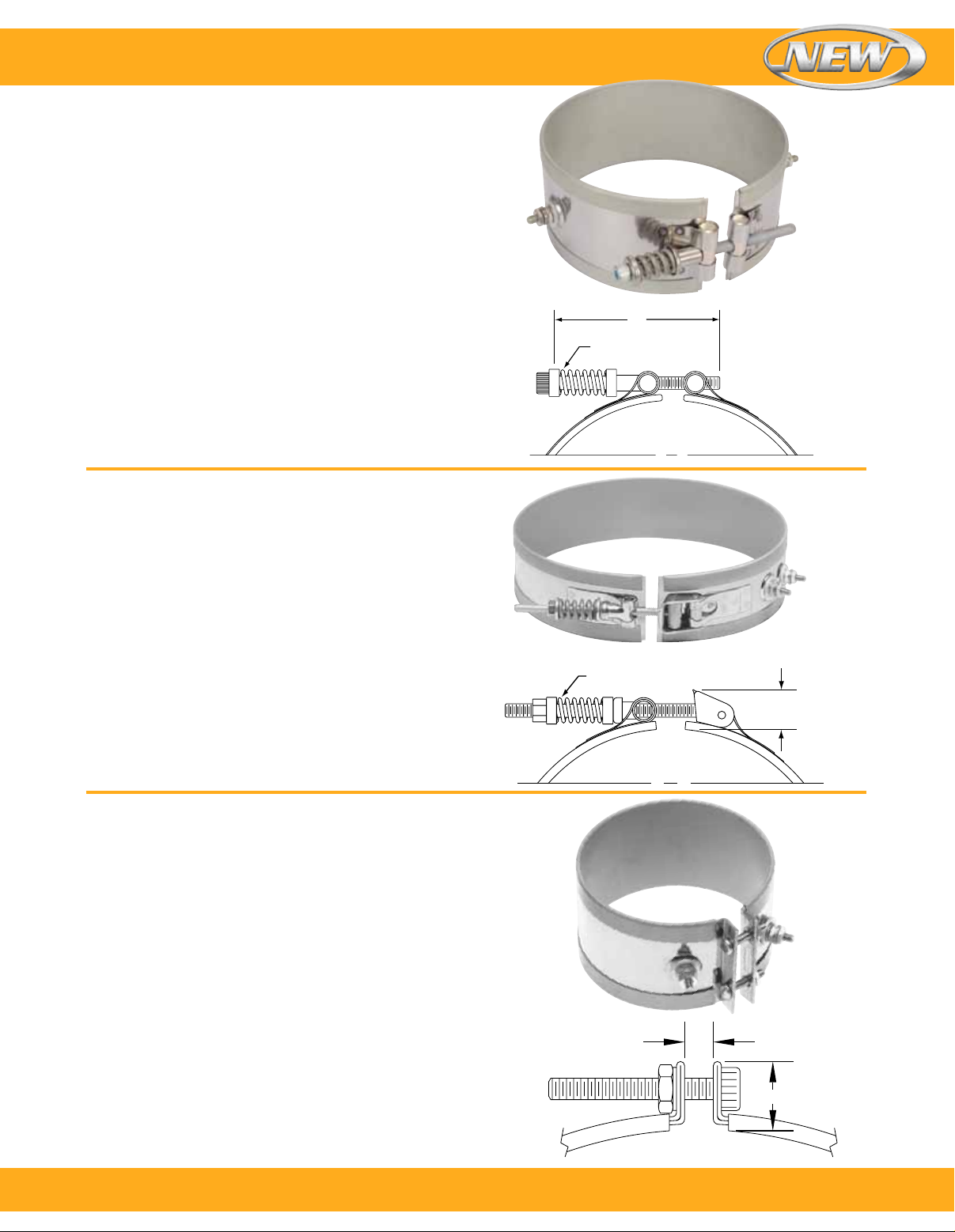
Band Heaters
Construction/Clamping Variations
Spring Loaded with Built-In Bracket
The heavy duty stainless steel spring with built-in bracket
is a variation on the basic Duraband® design. It is available
with any screw or lead termination and construction
variation. It is recommended for heaters over 305 mm (12")
in diameter, and for any diameter heater used in the vertical
position, to prevent the heater from slipping off the machine.
The springs provide constant tension, therefore maintaining
optimum surface contact against the cylinder being heated.
Type SL—One-Piece Band
Minimum ID: 101.6 mm (4")
Minimum Width: 31.8 mm (1¹⁄₄")
Type NSL—Two-Piece Band
Minimum ID: 101.6 mm (4")
Minimum Width: 31.8 mm (1¹⁄₄")
Type NEL—One-Piece Expandable Band
Minimum ID: 101.6 mm (4")
Minimum Width: 31.8 mm (1¹⁄₄")
Latch and Trunnion
The latch and trunnion clamping system is available with any
screw or lead termination and construction variation.
It is ideal in absorbing thermal expansion due to the spring
loading on the screws. The latch fully opens, facilitating
installation on large diameter cylinders. The outer sheath
is made from a low thermal expansion alloy.
4"
Stainless Steel
Spring
Type SL shown
Type LT—One-Piece Band
Minimum ID: 177.8 mm (7")
Minimum Width: 38.1 mm (1¹⁄₂")
Type LS—Two-Piece Band
Minimum ID: 177.8 mm (7")
Minimum Width: 38.1 mm (1¹⁄₂")
Type LE—One-Piece Expandable Band
Minimum ID: 177.8 mm (7")
Minimum. Width: 38.1 mm (1¹⁄₂")
Bent-Up Flange (Ears)
The bent-up flange clamping is available with any screw or
lead termination and construction variation. The outer sheath
is made from a low thermal expansion alloy. The bent-up
flange design is best suited for narrow band heaters with
small diameters.
Type FB—One-Piece Band
Minimum ID: 25.4 mm (1")
Minimum Width: 19.1 mm (³⁄₄")
Type FS—Two-Piece Band
Minimum ID: 50.8 mm (2")
Minimum Width: 19.1 mm (³⁄₄")
Type FE—One-Piece Expandable Band
Minimum ID: 63.5 mm (2¹⁄₂")
Minimum Width: 31.8 mm (1¹⁄₄")
Type LT shown
Stainless
Steel Spring
¹³⁄₁₆"
Type FB shown
¼"
Nominal
Note: The bent-up flange design should only be used when other
clamping methods are not suitable for a specific application. OMEGA
recommends built-in strap clamping be used whenever possible,
especially on large diameter heaters, because it provides superior
clamping power.
⁹⁄₁₆"
To order, call 1-800-826-6342 or shop online at omega.com
SM
7
Page 8
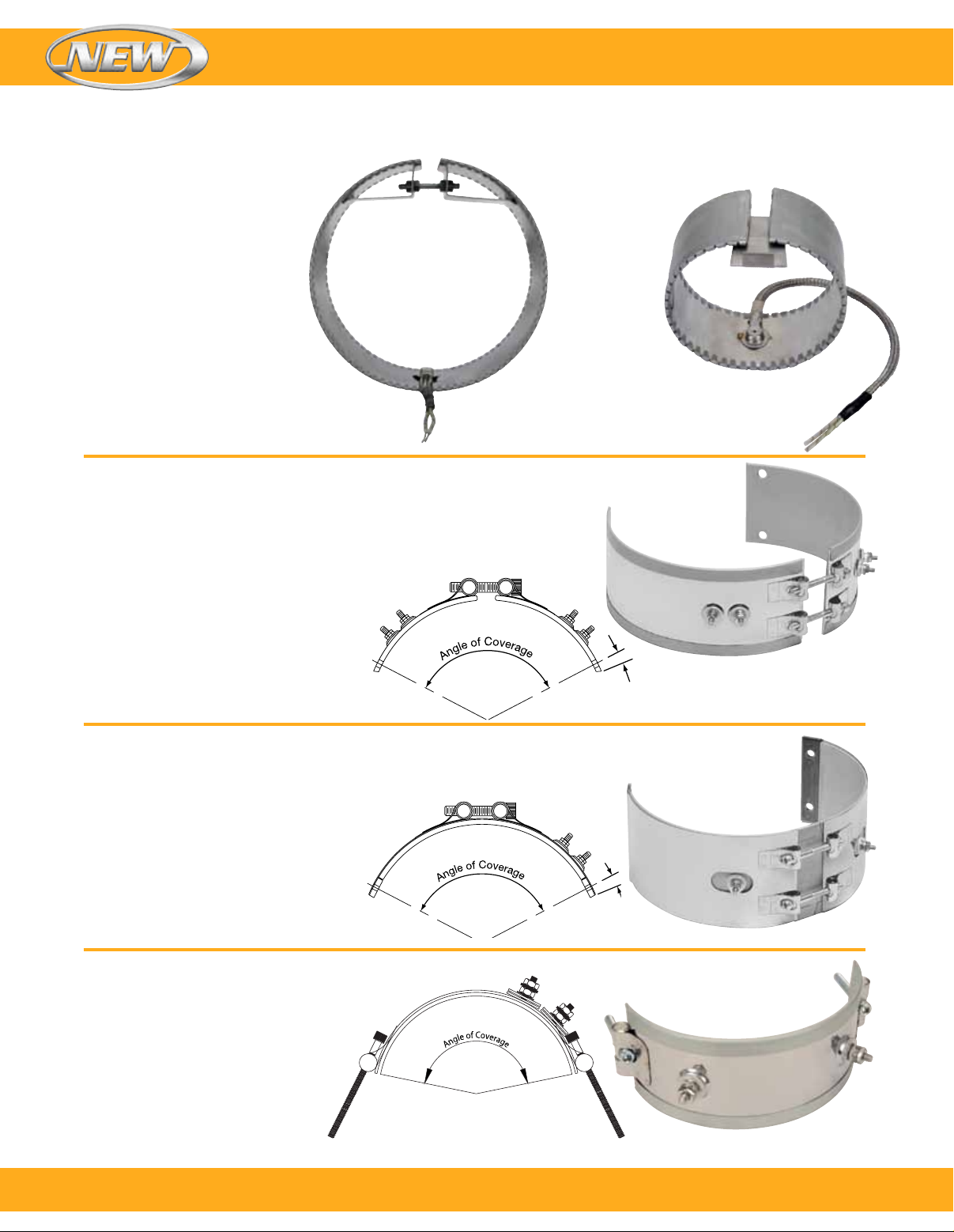
Band Heaters
Internal Reverse Bands
Type RN—Internal Reverse Band
(with Bracket Clamping)
This construction style is used to heat
cylindrical surfaces from the inside on
heaters 140 mm (5¹⁄₂") diameter
and larger.
Type RNB—Reverse
1-Piece Construction
ID: 139.7 to 2854 mm (5¹⁄₂ to 10")
Width: 25.4 to 88.9 mm (1" to 3¹⁄₂")
Maximum Voltage: 240 Vac
Type RNS—Reverse
2-Piece Construction
ID: 254 to 508 mm (10 to 20")
Width: 25.4 to 88.9 mm (1 to 3¹⁄₂")
Maximum Voltage: 240 Vac
For inside diameters greater than 508 mm (20"),
contact OMEGA with your requirements.
Type RNS shown
Partial Coverage
Type NS—2-Piece with Built-In Brackets
Partial coverage band heaters are normally required when
holes and cutouts will not allow the heater to sufficiently
clear the machine obstructions. The preferred method
of construction is the two-piece band heater
with built-in brackets as illustrated. The heater
is screwed down to the cylinder at the ends
and the built-in low thermal expansion strap
pulls the heater tightly against the cylinder
being heated. The standard center of hole
to edge of heater dimension is 6.3 mm (¹⁄₄").
When ordering, please provide the angle
of coverage from center to center of the
mounting screw holes as shown.
Type RTWL—Internal Reverse Band
(with Wedge Lock Clamping)
This construction style is used to heat cylindrical
surfaces from the inside on heaters less than
127 mm (5") outside diameter.
ID: Less than 139.7 mm (5¹⁄₂")
Width: 25.4 to 88.9 mm (1 to 3¹⁄₂")
¹⁄₄"
Type PS—One-Piece with Two-Piece Separate
Strap with Padded Ends
The alternate method of partial coverage construction is
the one-piece band heater with a separate two-piece strap.
The two-piece strap itself is screwed down
at the padded ends, allowing the heater to
float between the pads as illustrated. When
the strap is tightened, it will pull the heater
against the cylinder being heated. The
standard center of hole to edge of heater
dimension is 6.3 mm (¹⁄₄"). When ordering,
please provide the angle of coverage from
center to center of the mounting screw holes
as shown.
Type NB—One-Piece with Built-In
Strap Clamping
Another alternate method of partial
coverage construction. The one piece
with clamp screws on both sides allows
it to be secured to anchor points on either
side of a barrel without drilling holes into
the barrel.
8
To order, call 1-800-826-6342 or shop online at omega.com
¹⁄₄"
SM
Page 9
Band Heaters
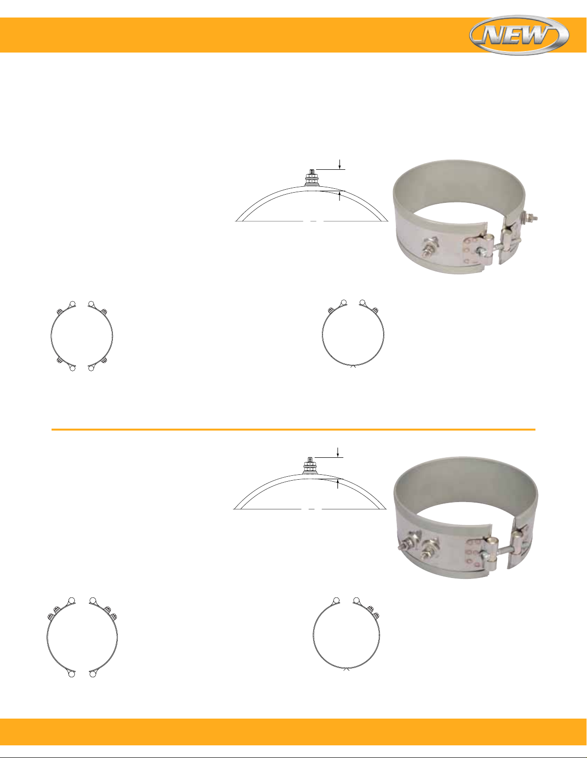
Terminations—Stainless Steel Power Terminals: Type T1, Type T2 and Type T3
Available on any clamping or construction variation, the
specially designed stainless steel power terminals are
internally connected to the heater and are resistant to
over-torquing.
Type T1–Screw Terminals
One-Piece Band
Standard Termination Location: Each side
of gap; center of width
Minimum Inside Diameter: 50.8 mm (2")
Minimum Width: 22.2 mm (⁷⁄₈")
Post Terminals: 10-32 standard except
8-32 on <1" wide heaters and heaters with ID <3"
Maximum Volts/Amps: 480 Vac/25 A (10-32) or 20 A (8-32)
Two-Piece Band
Standard Termination Location:
Next to gaps on each half; center of width
Minimum Inside Diameter: 50.8 mm (2")
Minimum Width: 22.2 mm (⁷⁄₈")
Post Terminals: 10-32 standard except
8-32 on <1" wide heaters and heaters with
ID <3"
Maximum Volts/Amps: 480 Vac/25 A
(10-32) or 20 A (8-32) each half
Considered standard on most band heaters
unless otherwise specified.
The screw terminals are virtually unbreakable. Secure
tightening of the electrical connections is essential for safety
and long heater life.
⁷⁄₈"
One-Piece Expandable Band
Standard Termination Location:
Each side of gap; center of width
Minimum Inside Diameter:
63.5 mm (2¹⁄₂")
Minimum Width: 31.8 mm (1¹⁄₄")
Post Terminals: 10-32 standard
except 8-32 on heaters with ID <3"
Maximum Volts/Amps: 480 Vac/25 A
(10-32) or 20 A (8-32)
Type T2–Screw Terminals
One-Piece Band
Standard Termination Location: Next to gap;
center of width
Minimum Inside Diameter: 50.8 mm (2")
Minimum Width: 22.2 mm (⁷⁄₈")
Post Terminals: 10-32 standard except
8-32 on <1" wide heaters and heaters with ID <3"
Maximum Volts/Amps: 480 Vac/25 A (10-32) or
20 A (8-32)
Two-Piece Band
Standard Termination Location: Next to
same gap on each half; center of width
Minimum Inside Diameter: 50.8 mm (2")
Minimum Width: 22.2 mm (⁷⁄₈")
Post Terminals: 10-32 standard except
8-32 on <1" wide heaters and heaters
with ID <3"
Maximum Volts/Amps: 480 Vac/25 A
(10-32) or 20 A (8-32) each half
⁷⁄₈"
Recommended for narrow band heaters
where screw terminals are preferred or the
C2 terminal box protection is required.
One-Piece Expandable Band
Standard Termination Location:
Next to gap; center of width
Minimum Inside Diameter:
63.5 mm (2¹⁄₂")
Minimum Width: 31.8 mm (1¹⁄₄")
Post Terminals: 10-32 standard
except 8-32 on heaters with ID <3"
Maximum Volts/Amps: 480 Vac/25 A
(10-32) or 20 A (8-32)
To order, call 1-800-826-6342 or shop online at omega.com
SM
9
Page 10
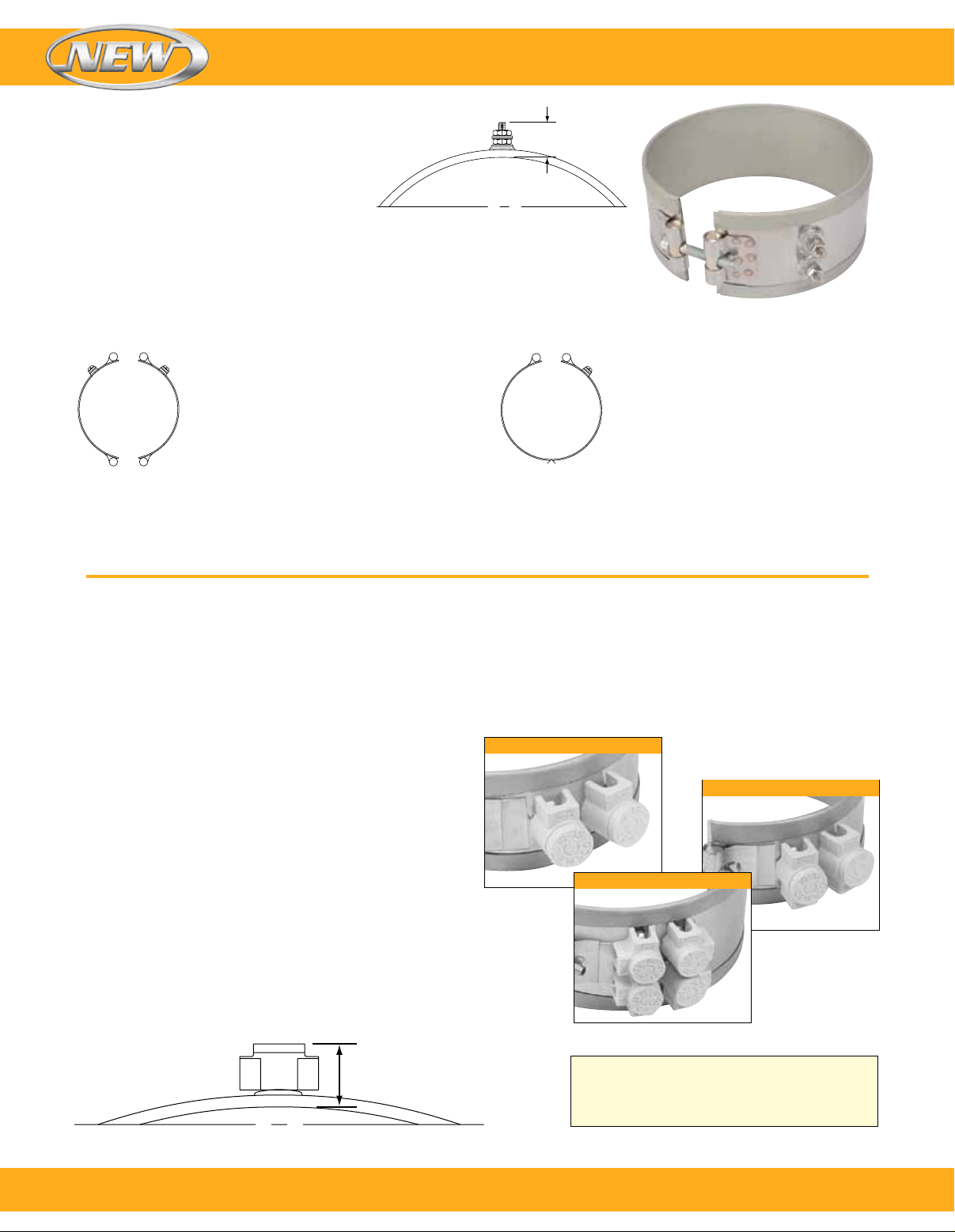
Terminations
Type T3–Screw Terminals
One-Piece Band
Standard Termination Location:
Next to gap; across center of width
Minimum Inside Diameter: 50.8 mm (2")
Minimum Width: 50.8 mm (2")
Post Terminals: 10-32 standard except 8-32 on
50.8 to 63.5 mm (2 to 2¹⁄₂") wide heaters and
heaters with ID <3"
Maximum Volts/Amps: 480 Vac/25 A (10-32) or
20 A (8-32)
Band Heaters
⁷⁄₈"
The preferred design on band heaters over
76.2 mm (3") wide or when C3 terminal box
is required.
Two-Piece Band
Standard Termination Location:
Next to same gap on each half;
across center of width
Minimum Inside Diameter: 50.8 mm (2")
Minimum Width: 50.8 mm (2")
Post Terminals: 10-32 standard except
8-32 on 50.8 to 63.5 mm (2 to 2¹⁄₂") wide
heaters and heaters with ID <3"
Maximum Volts/Amps: 480 Vac/
25 A (10-32) or 20 A (8-32) each half
One-Piece Expandable Band
Standard Termination Location:
Next to gap; across center of width
Minimum Inside Diameter:
63.5 mm (2¹⁄₂")
Minimum Width: 50.8 mm (2")
Post Terminals: 10-32 standard
except 8-32 on 50.8 to 63.5 mm
(2 to 2¹⁄₂") wide heaters and heaters
with ID <3"
Maximum Volts/Amps: 480 Vac/
25A (10-32) or 20 A (8-32)
Optional Igloo™ Ceramic Covers for Heaters with Screw Terminals
Igloo™ ceramic terminal covers consist of two individual ceramic parts.
Unlike conventional ceramic caps, Igloo fully insulates any
standard #8 or #10 terminal lugs used for electrical hook-ups.
Limitations
To assemble Igloo covers, terminals should be at least
22 mm (⁷⁄₈") apart
Minimum ID: 50.8 mm (2")
Minimum Width: 31.7 mm (1¹⁄₄")
Double Port In-Line
Single Port
Three types of Igloo™ bases are available:
Type C6–Double Port In-Line model number: CER-101-104
Type C7–Double Port 90° model number: CER-101-106
Type C8–Single Port model number: CER-101-107
™ Caps are Available in the Following Three
Igloo
Screw Terminal Sizes:
10-32–model number: CER-102-101
1 0-24–model number: CER-102-104
8-32–model number: CER-102-105
When ordering, specify the type of Igloo and the screw
terminal size.
1³⁄₃₂"
10
To order, call 1-800-826-6342 or shop online at omega.com
Double Port 90°
CAUTION: Exposed electrical wiring on band
heater installations is a violation of Electrical
Safety Codes including O.S.H.A.
SM
Page 11
Band Heaters
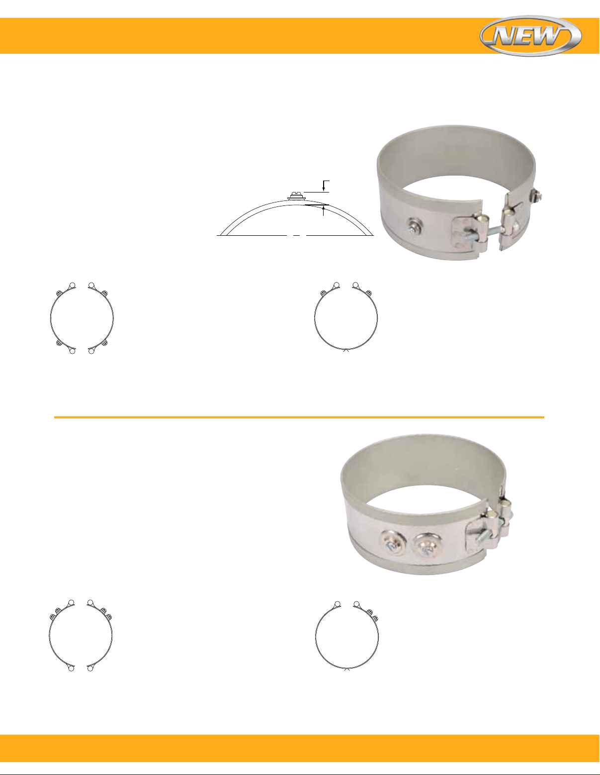
Terminations—Low-Profile Button Terminals: Type B1, Type B2 and Type B3
Available on any clamping or construction variation, the
specially designed stainless steel button terminals are
internally connected to the heater and are resistant to
Type B1–Button Terminals
One-Piece Band
Standard Termination Location: Each side
of gap; center of width
Minimum Inside Diameter: 50.8 mm (2")
Minimum Width: 38.1 mm (1¹⁄₂")
Screw Size: 10-32 standard except
6-32 on IDs <5"
Maximum Volts: 480 Vac
Maximum Amps: 25 A (10-32) or 20 A (6-32)
Two-Piece Band
Standard Termination Location:
Next to gaps on each half; center of width
Minimum Inside Diameter: 50.8 mm (2")
Minimum Width: 38.1 mm (1¹⁄₂")
Screw Size: 10-32 standard except
6-32 on IDs <5"
Maximum Volts/Amps: 480 Vac/25 A
(10-32) or 20 A (6-32) each half
over-torquing while offering a low profile for tight spaces.
They are virtually unbreakable. Secure tightening of the
electrical connections is essential for safety and long
heater life.
½"
One-Piece Expandable Band
Standard Termination Location:
Each side of gap; center of width
Minimum Inside Diameter:
63.5 mm (2¹⁄₂")
Minimum Width: 38.1 mm (1¹⁄₂")
Screw Size: 10-32 standard except
6-32 on IDs <5"
Maximum Volts/Amps: 480 Vac/25 A
(10-32) or 20 A (6-32)
Type B2–Button Terminals
One-Piece Band
Standard Termination Location: Next to gap;
center of width
Minimum Inside Diameter: 50.8 mm (2")
Minimum Width: 38.1 mm (1¹⁄₂")
Screw Size: 10-32 standard except 6-32 on IDs <5"
Maximum Volts: 480 Vac
Maximum Amps: 25 A (10-32) or 20 A (6-32)
Two-Piece Band
Standard Termination Location: Next to
same gap on each half; center of width
Minimum Inside Diameter: 50.8 mm (2")
Minimum Width: 38.1 mm (1¹⁄₂")
Screw Size: 10-32 standard except
6-32 On IDs <5"
Maximum Volts/Amps: 480 Vac/
25 A (10-32) or 20 A (6-32) each half
One-Piece Expandable Band
Standard Termination Location:
Next to gap; center of width
Minimum Inside Diameter:
63.5 mm (2¹⁄₂")
Minimum Width: 38.1 mm (1¹⁄₂")
Screw Size: 10-32 standard except
6-32 on IDs <5"
Maximum Volts/Amps: 480 Vac/25 A
(10-32) or 20 A (6-32)
To order, call 1-800-826-6342 or shop online at omega.com
SM
11
Page 12
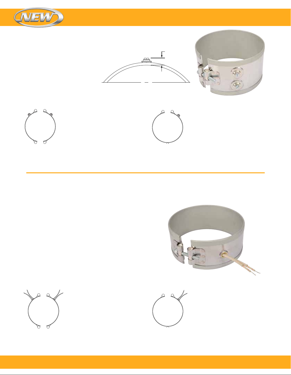
Type B3–Button Terminals
Band Heaters
One-Piece Band
Standard Termination Location: Next to gap;
across center of width
Minimum Inside Diameter: 50.8 mm (2")
Minimum Width: 60.3 mm (2³⁄₈")
Screw Size: 10-32 standard except
6-32 on IDs <5"
Maximum Volts: 480 Vac
Maximum Amps: 25 A (10-32) or 20 A (6-32)
½"
Two-Piece Band
Standard Termination Location:
Next to same gap on each half;
across center of width
Minimum Inside Diameter: 50.8 mm (2")
Minimum Width: 60.3 mm (2³⁄₈")
Screw Size: 10-32 standard except
6-32 on IDs <5"
Maximum Volts/Amps: 480 Vac/25 A
(10-32) or 20 A (6-32) each half
Plain Lead Wire Terminations: Type L1, Type L2 and Type L4
Available on Any Clamping or Construction Variation
One-Piece Expandable Band
Standard Termination Location:
Next to gap; across center of width
Minimum Inside Diameter:
63.5 mm (2¹⁄₂")
Minimum Width: 60.3 mm (2³⁄₈")
Screw Size: 10-32 standard except
6-32 On IDs <5"
Maximum Volts/Amps: 480 Vac/25 A
(10-32) or 20 A (6-32)
Type L1–Straight Lead Wires
The lead wires exit through a brass eyelet. The
standard flexible leads are 254 (10") long with 76 (3")
of fiberglass sleeving.
Note: If longer leads are required, specify when ordering.
One-Piece Band
Standard Termination Location: Next to gap;
center of width
Minimum Inside Diameter: 50.8 mm (2")
Minimum Width: 25.4 mm (1")
Maximum Volts: 480 Vac
Maximum Amps: 10 A
Two-Piece Band
Standard Termination Location:
Next to same gap on each half;
center of width
Minimum Inside Diameter:
50.8 mm (2")
Minimum Width: 25.4 mm (1")
Maximum Volts: 480V each half
Maximum Amps: 10 A each half
One-Piece Expandable Band
Standard Termination Location:
Next to gap; center of width
Minimum Inside Diameter:
63.5 mm (2¹⁄₂")
Minimum Width: 31.8 mm (1¹⁄₄")
Maximum Volts: 480V
Maximum Amps: 10 A
12
To order, call 1-800-826-6342 or shop online at omega.com
SM
Page 13
Band Heaters
Terminations
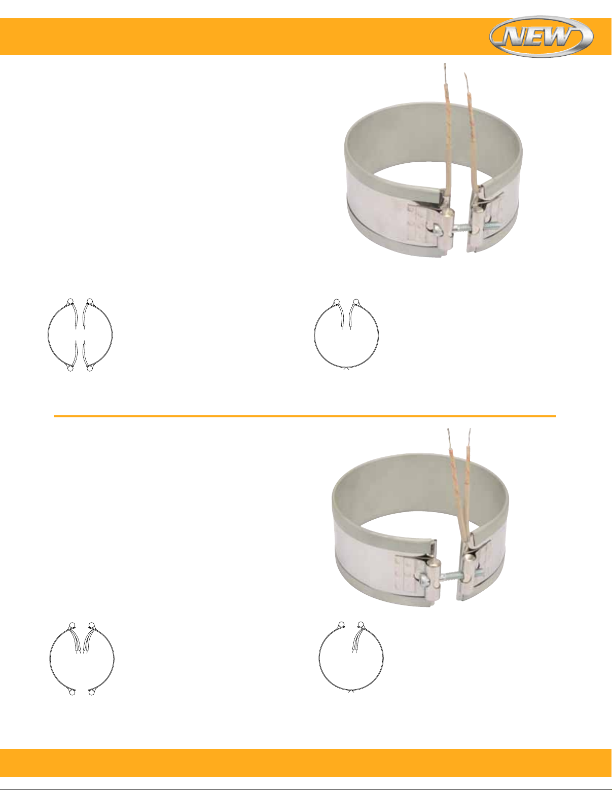
Type L2–Straight Lead Wires
Type L2 is the preferred termination on all small diameter
and small width band heaters. The standard flexible
leads are 254 mm (10") long with 76 mm (3") of
fiberglass sleeving.
Note: If longer leads are required, specify when ordering.
One-Piece Band
Standard Termination Location: Each side of gap;
edge of width
Minimum Inside Diameter: 22.2 mm (⁷⁄₈")
Minimum Width: 19.1 mm (³⁄₄")
Maximum Volts: 480 Vac
Maximum Amps: 10 A
Two-Piece Band
Standard Termination Location:
Each side of each gap; edge of width
Minimum Inside Diameter: 50.8 mm (2")
Minimum Width: 19.1 mm (³⁄₄")
Maximum Volts: 480V each half
Maximum Amps: 10 A each half
Type L4–Straight Lead Wires
Type L4 is a suitable lead termination for small band
heaters. The standard flexible leads are 254 mm (10") long
with 76 mm (3") of fiberglass sleeving.
Note: If longer leads are required, specify when ordering.
One-Piece Band
Standard Termination Location: Same side of gap;
edge of width
Minimum Inside Diameter: 22.2 mm (⁷⁄₈")
Minimum Width: 25.4 mm (1")
Maximum Volts: 480 Vac
Maximum Amps: 10 A
One-Piece Expandable Band
Standard Termination Location:
Each side of gap; edge of width
Minimum Inside Diameter:
63.5 mm (2¹⁄₂")
Minimum Width: 31.8 mm (1¹⁄₄")
Maximum Volts: 480V
Maximum Amps: 10 A
Two-Piece Band
Standard Termination Location:
Each side of same gap; center of width
Minimum Inside Diameter: 50.8 mm (2")
Minimum Width: 25.4 mm (1")
Maximum Volts: 480V each half
Maximum Amps: 10 A each half
One-Piece Expandable Band
Standard Termination Location:
Same side of gap; edge of width
Minimum Inside Diameter:
63.5 mm (2¹⁄₂")
Minimum Width: 31.8 mm (1¹⁄₄")
Maximum Volts: 480 Vac
Maximum Amps: 10 A
To order, call 1-800-826-6342 or shop online at omega.com
SM
13
Page 14
Band Heaters
Abrasion Resistant Lead Terminations:
Type W1, Type W2, Type W2M, Type W3, Type W4 and Type W5M
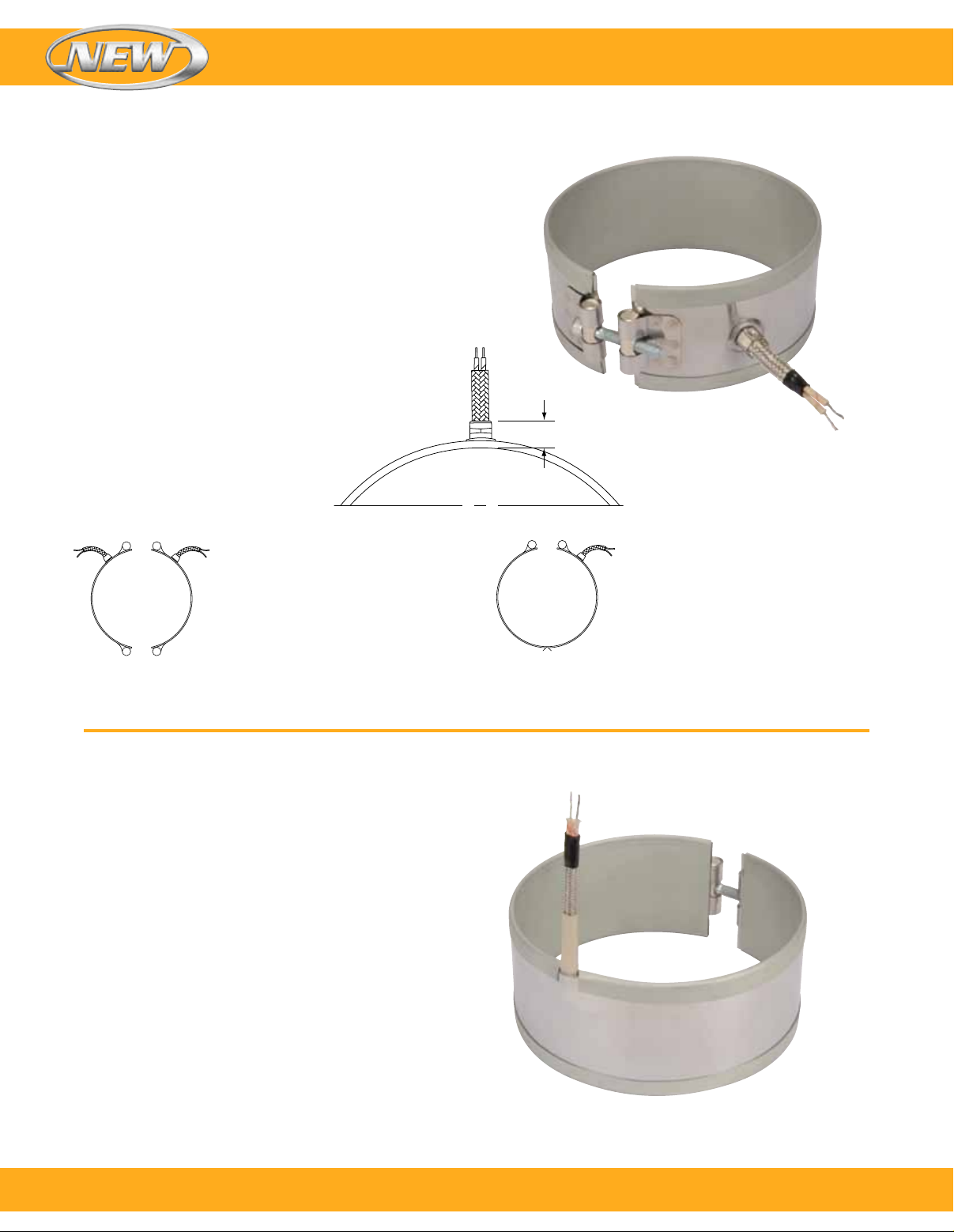
Type W1–Straight Wire Braid Leads
Available on any clamping or construction variation.
Wire braid leads offer sharp bending not possible with
armor cable.
The standard leads are 254 mm (10") of wire braid over
305 mm (12") of flexible leads.
Note: If longer leads are required, specify when ordering.
One-Piece Band
Standard Termination Location:
Next to gap; center of width
Minimum Inside Diameter: 50.8 mm (2")
Minimum Width: 25.4 mm (1")
Maximum Volts: 480 Vac
Maximum Amps: 10 A
⁹⁄₁₆"
Two-Piece Band
Standard Termination Location:
Next to same gap on each half;
center of width
Minimum Inside Diameter:
50.8 mm (2")
Minimum Width: 25.4 mm (1")
Maximum Volts: 480 Vac each half
Maximum Amps: 10 A each half
Type W2–Wire Braid Leads
The W2 wire braid exits at 180° from the gap for special
nozzle heating applications. Sleeving is used for additional
protection. The standard leads are 254 mm (10") of wire
braid over 305 mm (12") of flexible leads with 76 mm (3")
of fiberglass sleeving.
Note: If longer leads are required, specify when ordering.
Type W2 is not available on two-piece or one-piece expandable
Duraband heaters.
One-Piece Band
Standard Termination Location:
Opposite the gap; edge of width
Minimum Inside Diameter: 22.2 mm (⁷⁄₈")
Minimum Width: 28.6 mm (1¹⁄₈")
Maximum Volts: 480 Vac
Maximum Amps: 10 A
One-Piece Expandable Band
Standard Termination Location:
Next to gap; center of width
Minimum Inside Diameter:
63.5 mm (2¹⁄₂")
Minimum Width: 31.8 mm (1¹⁄₄")
Maximum Volts: 480 Vac
Maximum Amps: 10 A
14
To order, call 1-800-826-6342 or shop online at omega.com
SM
Page 15
Band Heaters
Terminations
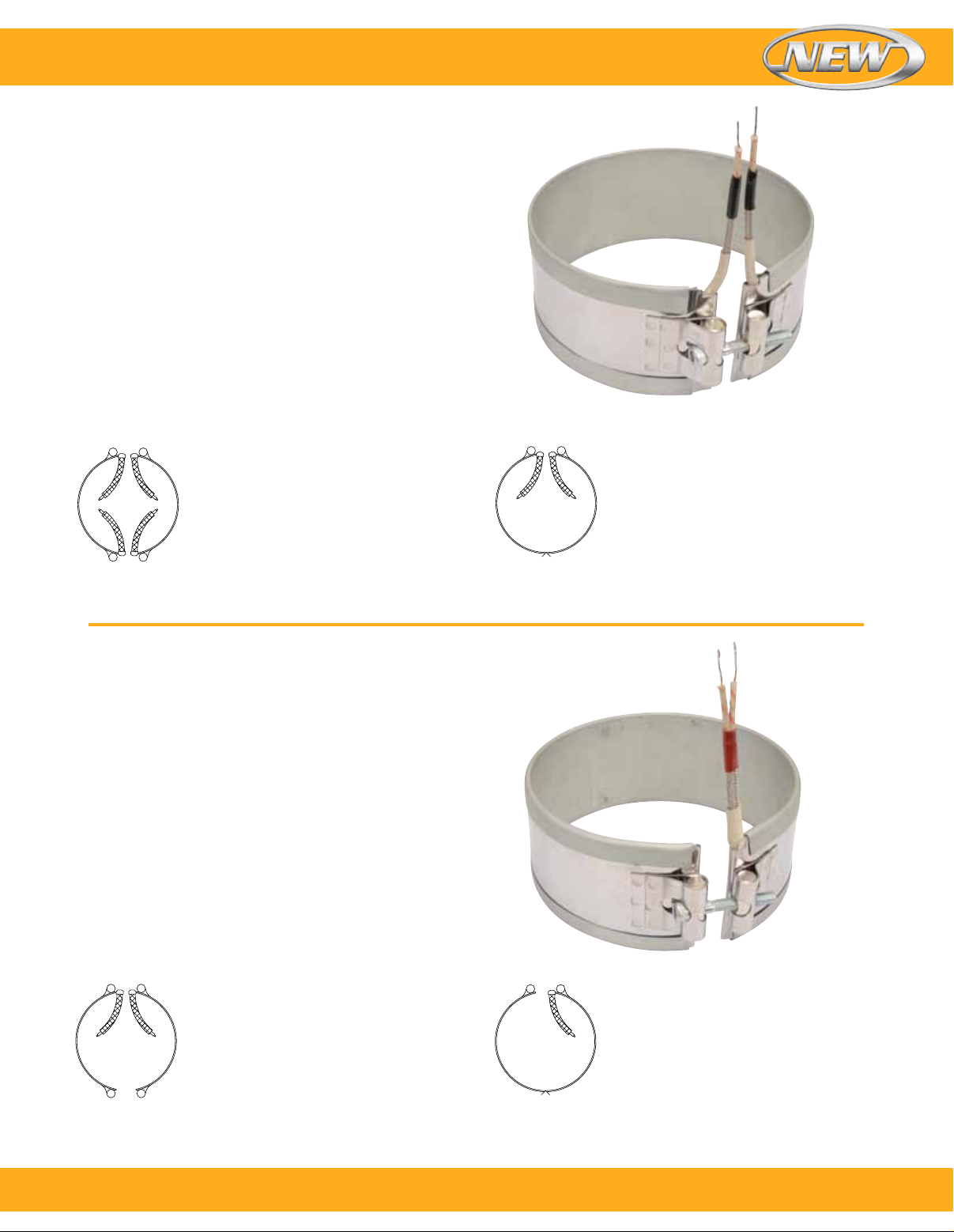
Type W3–Single Wire Braid Leads
Highly recommended for nozzle heating applications. The
standard leads are 254 mm (10") of wire braid over 305 mm
(12") of flexible leads with 76 mm (3") of fiber glass sleeving.
Note: If longer leads are required, specify when ordering.
One-Piece Band
Standard Termination Location: Each side of gap;
edge of width
Minimum Inside Diameter: 19.1 mm (³⁄₄")
Minimum Width: 22.2 mm (⁷⁄₈")
Maximum Volts: 480 Vac
Maximum Amps: 10 A
Two-Piece Band
Standard Termination Location:
Each side of each gap; edge of width
Minimum Inside Diameter:
50.8 mm (2")
Minimum Width: 19.1 mm (³⁄₄")
Maximum Volts: 480 Vac each half
Maximum Amps: 10 A each half
Type W4–Wire Braid Leads on One Side
A suitable termination for nozzle heating applications.
The standard leads are 254 mm (10") of wire braid over
305 mm (12") of flexible leads.
Note: If longer leads are required, specify when ordering.
One-Piece Band
Standard Termination Location: Next to gap;
edge of width
Minimum Inside Diameter: 22.2 mm (⁷⁄₈")
Minimum Width: 25.4 mm (1")
Maximum Volts: 480 Vac
Maximum Amps: 10 A
One-Piece Expandable Band
Standard Termination Location:
Each side of gap; edge of width
Minimum Inside Diameter:
19.0 mm (2¹⁄₂")
Minimum Width: 31.8 mm (1¹⁄₄")
Maximum Volts: 480 Vac
Maximum Amps: 10 A
Two-Piece Band
Standard Termination Location: Next to
same gap on each half; edge of width
Minimum Inside Diameter: 50.8 mm (2")
Minimum Width: 25.4 mm (1")
Maximum Volts: 480 Vac each half
Maximum Amps: 10 A each half
One-Piece Expandable Band
Standard Termination Location:
Next to gap; edge of width
Minimum Inside Diameter:
63.5 mm (2¹⁄₂")
Minimum Width: 31.8 mm (1¹⁄₄")
Maximum Volts: 480 Vac
Maximum Amps: 10 A
To order, call 1-800-826-6342 or shop online at omega.com
SM
15
Page 16
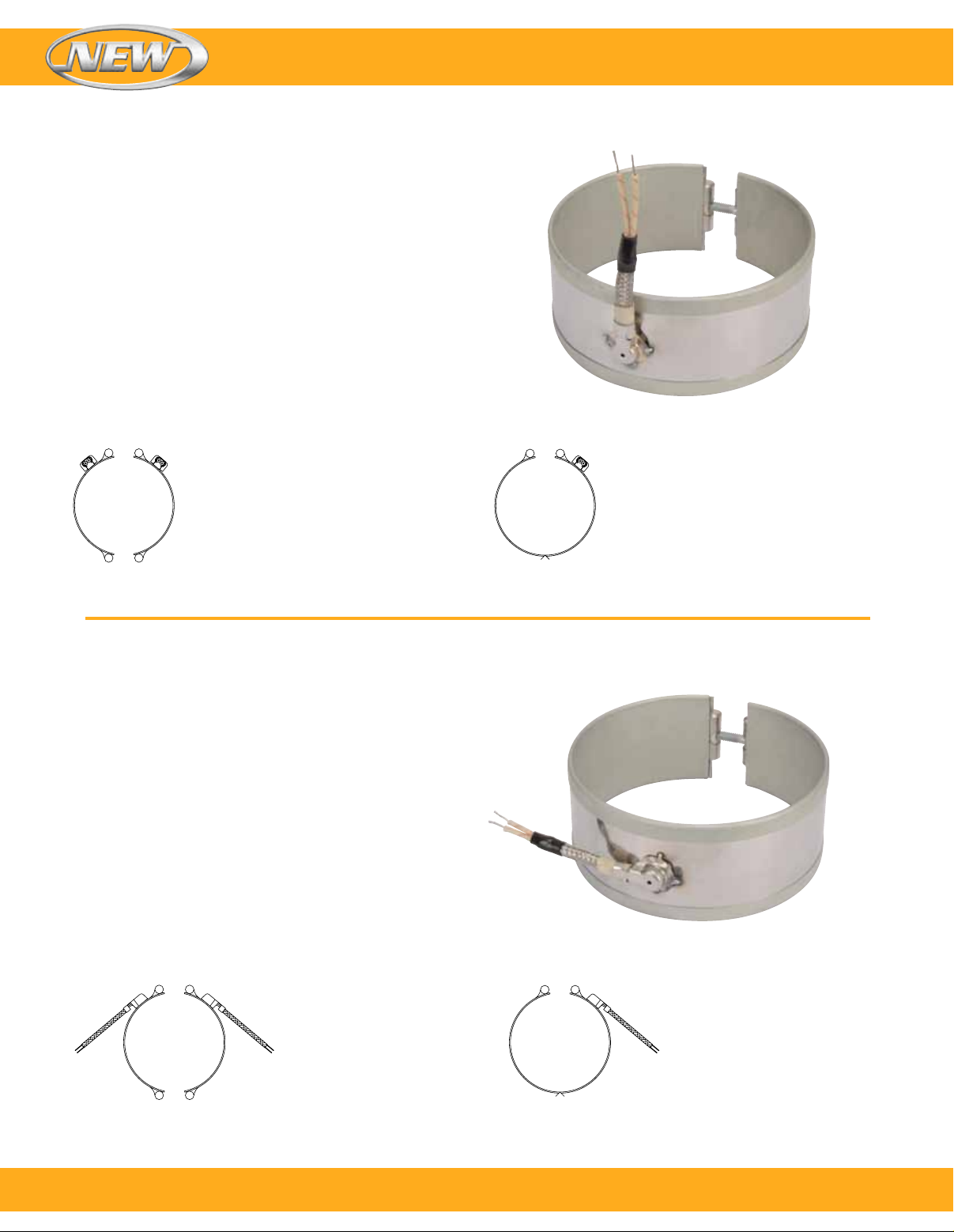
Type W2M–Right-Angle Wire Braid Leads, 90° to Heater
Stainless steel wire braid exits perpendicular to the heater
centerline through a low profile stainless steel cap.
This cap acts as a strain relief which protects against
excessive flexing or pulling of the lead wire. The standard
leads are 254 mm (10") of wire braid over 305 mm (12")
of flexible leads.
Note: If longer leads are required, specify when ordering.
Stainless steel construction may be required for widths of
22.2 mm (
One-Piece Band
Standard Termination Location: Opposite of gap;
center of width
Minimum Inside Diameter: 38.1 mm (1¹⁄₂")
Minimum Width: 31.8 mm (1¹⁄₄")
Maximum Volts: 480 Vac
Maximum Amps: 10 A
7
") to 41.3 mm (1
⁄
8
5
").
⁄
8
Band Heaters
Two-Piece Band
Standard Termination Location: Next to
same gap on each half; center of width
Minimum Inside Diameter: 50.8 mm (2")
Minimum Width: 31.8 mm (1¹⁄₄")
Maximum Volts: 480 Vac each half
Maximum Amps: 10 A each half
Type W5M–Right-Angle Wire Braid Leads, Parallel to Heater
Stainless steel wire braid exits parallel to the heater
centerline through a low profile stainless steel cap.
This cap acts as a strain relief which protects against
excessive flexing or pulling of the lead wire. The standard
leads are 254 mm (10") of wire braid over 305 mm (12") of
flexible leads.
Note: If longer leads are required, specify when ordering.
Stainless steel construction may be required for widths of
22.2 mm (
One-Piece Band
Standard Termination Location: Opposite of gap;
center of width
Minimum Inside Diameter: 38.1 mm (1¹⁄₂")
Minimum Width: 31.8 mm (1¹⁄₄")
Maximum Volts: 480 Vac
Maximum Amps: 10 A
7
") to 41.3 mm (1
⁄
8
5
").
⁄
8
One-Piece Expandable Band
Standard Termination Location: Next to
gap; center of width
Minimum Inside Diameter:
63.5 mm (2¹⁄₂")
Minimum Width: 31.8 mm (1¹⁄₄")
Maximum Volts: 480 Vac
Maximum Amps: 10 A
16
Two-Piece Band
Standard Termination Location:
Next to same gap on each side;
center of width
Minimum Inside Diameter:
50.8 mm (2")
Minimum Width: 31.8 mm (1¹⁄₄")
Maximum Volts: 480 Vac each half
One-Piece Expandable Band
Standard Termination Location:
Next to gap; center of width
Minimum Inside Diameter:
63.5 mm (2¹⁄₂")
Minimum Width: 31.8 mm (1¹⁄₄")
Maximum Volts: 480 Vac
Maximum Amps: 10 A
Maximum Amps: 10 A each half
To order, call 1-800-826-6342 or shop online at omega.com
SM
Page 17
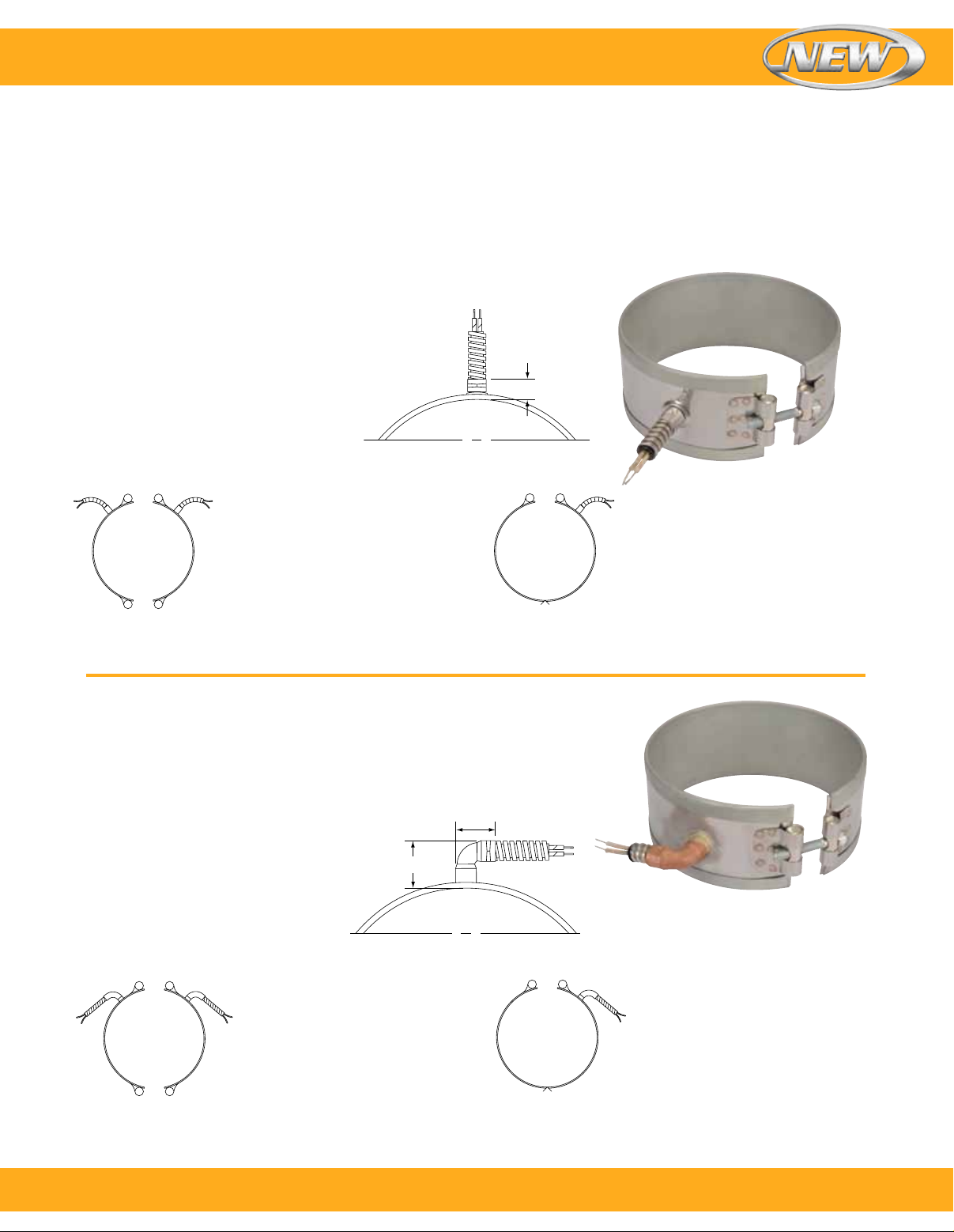
Band Heaters
Terminations—Armor Cable Terminations: Type R1, Type R2 and Type R3
Available on any clamping or construction variation. Armor
cable provides far superior protection to lead wires where
Type R1 – Straight Armor Cable
Type R1A–Galvanized armor cable, crimped
Type R1B–Stainless Steel armor cable, crimped
Type R1C–Galvanized armor cable, tack welded
One-Piece Band
Standard Termination Location:
Next to gap; center of width
Minimum Inside Diameter: 38.1 mm (1¹⁄₂")
Minimum Width: 25.4 mm (1")
Maximum Volts: 480 Vac
Maximum Amps: 10 A
Two-Piece Band
Standard Termination Location:
Next to same gap on each half;
center of width
Minimum Inside Diameter:
50.8 mm (2")
Minimum Width: 25.4 mm (1")
Maximum Volts/Amps:
480 Vac/10 A each half
abrasion is a constant problem. The standard leads are
254 mm (10") of armor cable over 305 mm (12") of flexible leads.
Note: If longer leads are required, specify when ordering.
Type R1D–Stainless Steel armor cable, tack welded
Type R1E–Galvanized armor cable, full silver brazing
Type R1F–Stainless Steel armor cable, fullsilver brazing
1"
One-Piece Expandable Band
Standard Termination Location:
Next to gap; center of width
Minimum Inside Diameter:
65.3 mm (2¹⁄₂")
Minimum Width: 31.8 mm (1¹⁄₄")
Maximum Volts/Amps: 480 Vac/10 A
Type R2–Right-Angle Armor Cable
Type R2A–Galvanized armor cable, crimped
Type R2B–Stainless Steel armor cable, crimped
Type R2C–Plain leads, no cable
One-Piece Band
Standard Termination Location:
Next to gap; center of width
Minimum Inside Diameter: 38.1 mm (1¹⁄₂")
Minimum Width: 31.8 mm (1¹⁄₄")
Maximum Volts: 480 Vac
Maximum Amps: 10 A
Two-Piece Band
Standard Termination Location:
Next to same gap on each half;
center of width
Minimum Inside Diameter:
50.8 mm (2")
Minimum Width: 31.8 mm (1¹⁄₄")
Maximum Volts/Amps:
480 Vac/10 A each half
1¼"
1¼"
One-Piece Expandable Band
Standard Termination Location:
Next to gap; center of width
Minimum Inside Diameter:
63.5 mm (2¹⁄₂")
Minimum Width: 31.8 mm (1¹⁄₄")
Maximum Volts/Amps: 480 Vac/10 A
To order, call 1-800-826-6342 or shop online at omega.com
SM
17
Page 18
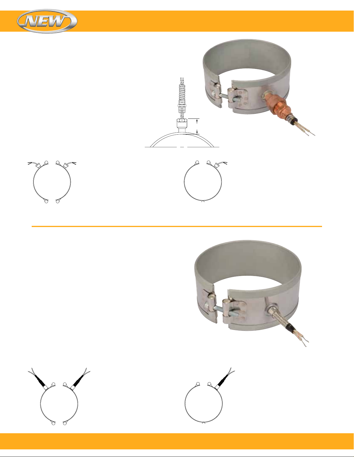
Type R3–Removable Armor Cable
Type R3A–Plain leads and female fitting
Type R3B–Leads, male adaptor and galvanized armor
Type R3C– Leads, male adaptor and stainless steel armor
Recommended on applications where removable armor is
required. The fitting will accept the standard armor cable
connector. The standard leads are 254 mm (10") of armor
cable over 305 mm (12") of flexible leads.
Note: If longer leads are required, specify when ordering.
One-Piece Band
Standard Termination Location: Next to gap;
center of width
Minimum Inside Diameter: 38.1 mm (1¹⁄₂")
Minimum Width: 31.7 mm (1¹⁄₄")
Maximum Volts/Amps: 480 Vac/10 A
Band Heaters
Type R3B shown
1⁵⁄₈"
Two-Piece Band
Standard Termination Location:
Next to same gap on each half;
center of width
Minimum Inside Diameter:
50.8 mm (2")
Minimum Width: 31.7 mm (1¹⁄₄")
Maximum Volts/Amps:
480 Vac/10 A each half
Type S1–Lead Wire Spring Strain Relief
Type S1A–Plain leads and strain relief spring
Type S1B–Stainless steel wire braided leads and strain
relief spring. 254 mm (10") of braid over 305 mm (12") of
flexible leads is standard.
A strain relief spring is attached to the heater at the
termination exit to reduce strain on leads subjected to
excessive flexing. The spring is 54 mm (2¹⁄₈") long.
The flexible standard leads are 254 mm (10") long with
76 mm (3") of fiberglass sleeving.
Note: If longer leads are required, specify when ordering.
One-Piece Band
Standard Termination Location: Next to gap;
center of width
Minimum Inside Diameter: 50.8 mm (2")
Minimum Width: 31.8 mm (1¹⁄₄")
Maximum Volts: 480 Vac
Maximum Amps: 10 A
One-Piece Expandable Band
Standard Termination Location:
Next to gap; center of width
Minimum Inside Diameter:
63.5 mm (2¹⁄₂")
Minimum Width: 31.8 mm (1¹⁄₄")
Maximum Volts/Amps: 480 Vac/10 A
Type S1B shown
18
Two-Piece Band
Standard Termination Location:
Next to same gap on each half;
center of width
Minimum Inside Diameter:
50.8 mm (2")
Minimum Width: 31.75 mm (1¹⁄₄")
Maximum Volts/Amps:
480 Vac/10 A each half
One-Piece Expandable Band
Standard Termination Location:
Next to gap; center of width
Minimum Inside Diameter:
63.5 mm (2¹⁄₂")
Minimum Width: 31.75 mm (1¹⁄₄")
Maximum Volts/Amps:
480 Vac/10 A
To order, call 1-800-826-6342 or shop online at omega.com
SM
Page 19
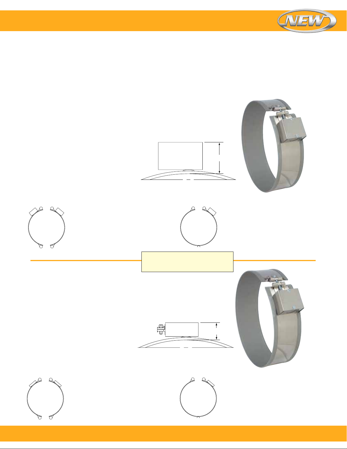
Band Heaters
Terminations—General Purpose Terminal Boxes: Type C2 and Type C5
Available with any construction or clamping variation. They
are a simple and economical way to protect employees from
electric shock or prevent electric shorts that can result from
exposed wiring on band heater electrical installations.
The heavy duty terminal boxes have 13 mm (¹⁄₂") knockouts
that will accept standard armor cable connectors. They
can be field assembled on band heaters that have a center
Type C2–Terminal Boxes
Type C2— Standard Box
C2A–Box only
C2B–with galvanized armor
One-Piece Band
Standard Termination Location:
Next to gap; center of width
Minimum Inside Diameter: 63.5 mm (2¹⁄₂")
Minimum Width: 25.4 mm (1")
Maximum Volts/Amps: 480 Vac/25 A
Two-Piece Band
Standard Termination Location: Next to
same gap on each half; center of width
Minimum Inside Diameter: 76.2 mm (3")
Minimum Width: 25.4 mm (1")
Maximum Volts/Amps: 480 Vac/25 A
each half
Type C5–Terminal Boxes
C2C–with stainless steel armor
C2D–with wire braid
Heater widths between 25 and 64 mm
(1 and 2¹⁄₂") require a minimum ID of
140 mm (5¹⁄₂") or greater.
distance between terminal screws of 22 mm (⁷⁄₈"). Boxes can
be pre-wired with galvanized armor, stainless steel armor,
wire braid or plain leads. If a low profile box with cable or
leads is required, it is strongly recommended to order it
pre-wired by the factory.
The standard leads are 254 mm (10") of cable or wire braid
over 305 mm (12") of flexible leads. If longer leads are
required, specify when ordering.
1¾"
Type C2 shown
One-Piece Expandable Band
Standard Termination Location:
Next to gap; center of width
Minimum Inside Diameter: 63.5 mm (2¹⁄₂")
Minimum Width: 25.4 mm (1")
Maximum Volts/Amps: 480 Vac/25 A
Type C5—Low Profile Box
C5A–Box only
C5B–with galvanized armor
C5C–with stainless steel armor
C5D–with wire braid
C5J–with plain leads
One-Piece Band
Standard Termination Location: Next to gap;
center of width
Minimum Inside Diameter: 63.5 mm (2¹⁄₂")
Minimum Width: 25.4 mm (1")
Maximum Volts/Amps: 480 Vac/25 A
Two-Piece Band
Standard Termination Location: Next to
same gap on each half; center of width
Minimum Inside Diameter: 76.2 mm (3")
Minimum Width: 25.4 mm (1")
Maximum Volts/Amps: 480 Vac/25 A
each half
1¹⁄₈"
Type C5 shown
One-Piece Expandable Band
Standard Termination Location:
Next to gap; center of width
Minimum Inside Diameter: 63.5 mm (2¹⁄₂")
Minimum Width: 25.4 mm (1")
Maximum Volts/Amps: 480 Vac/25 A
To order, call 1-800-826-6342 or shop online at omega.com
SM
19
Page 20
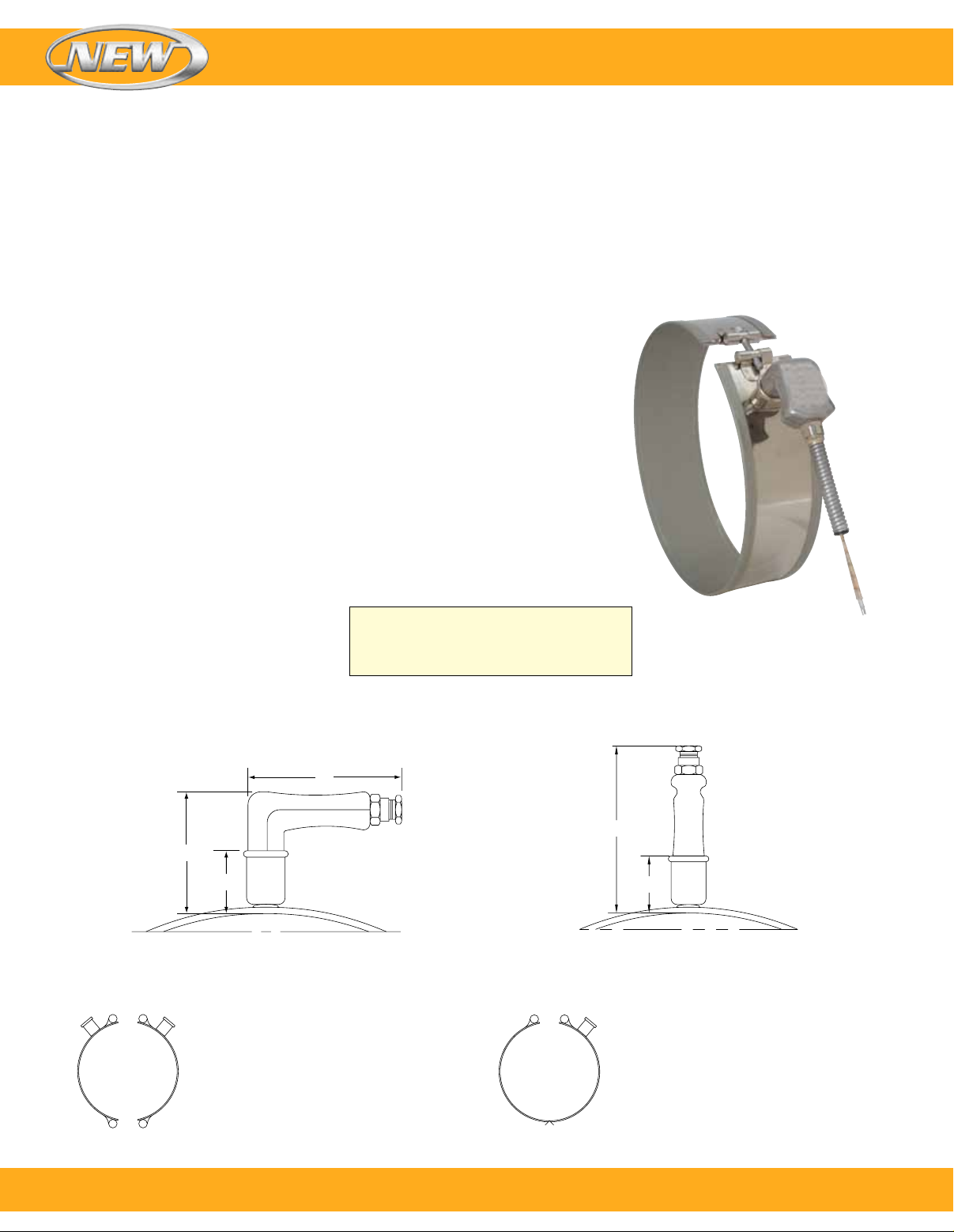
Band Heaters
Quick Disconnect Plugs: Type P1, Type P2, Type P3 and Type P4
Available on any construction or clamping variation. These
plug assemblies are highly recommended and should be
used whenever possible. The combination of plug and cup
assembly along with armor cable covered leads eliminates
all live exposed terminals or wiring that can be a potential
hazard to employees or machinery.
Type P1 and P3 assemblies are available with a straight or
right-angle plug. Type P2 and P4 plug assemblies have a
lower profile and are available with a straight plug only.
Type P1–High Temperature Quick Disconnect Plugs
Type P1
P1K–Cup assembly only
P1L–with straight plug
P1M–with 90° plug only
P1N–with straight plug and
galvanized cable
One-Piece Band
Standard Termination Location: Next to gap;
center of width
Minimum Inside Diameter: 50.8 mm (2")
Minimum Width: 38.1 mm (1¹⁄₂")
Plug Electrical Ratings
2-Pole 3-Wire Grounding
Maximum Volts: 250 Vac
Maximum Amps: 16 A
Maximum Temperature: 300°C (572°F)
P1O–with straight plug and stainless
steel cable
P1P–with straight plug and wire braid
P1Q–with 90° plug and galvanized cable
P1R–with 90° plug and stainless
steel cable
P1S–with 90° plug and wire braid
If width is between 38 and 51 mm
(1¹⁄₂ and 2"), minimum diameter is
140 mm (5¹⁄₂"). If width is greater than
64 mm (2"), minimum diameter is 64 mm (2")
To simplify installation, band heaters with these assemblies
can be supplied pre-wired, using high temperature
lead wires.
The standard leads are 254 mm (10") of armor cable over
(12") of flexible leads. If longer leads are required, specify
when ordering.
Type P1Q shown
20
3"
4³⁄₈"
2¹¹⁄₁₆"
1¹⁄₄"
Type P1M Type P1L
Two-Piece Band
Standard Termination Location:
Next to same gap on each half;
center of width
Minimum Inside Diameter: 50.8 mm (2")
Minimum Width: 38.1 mm (1¹⁄₂")
1¹⁄₄"
One-Piece Expandable Band
Standard Termination Location:
Next to gap; center of width
Minimum Inside Diameter:
63.5 mm (2¹⁄₂")
Minimum Width: 38.1 mm (1¹⁄₂")
To order, call 1-800-826-6342 or shop online at omega.com
SM
Page 21
Band Heaters
Terminations
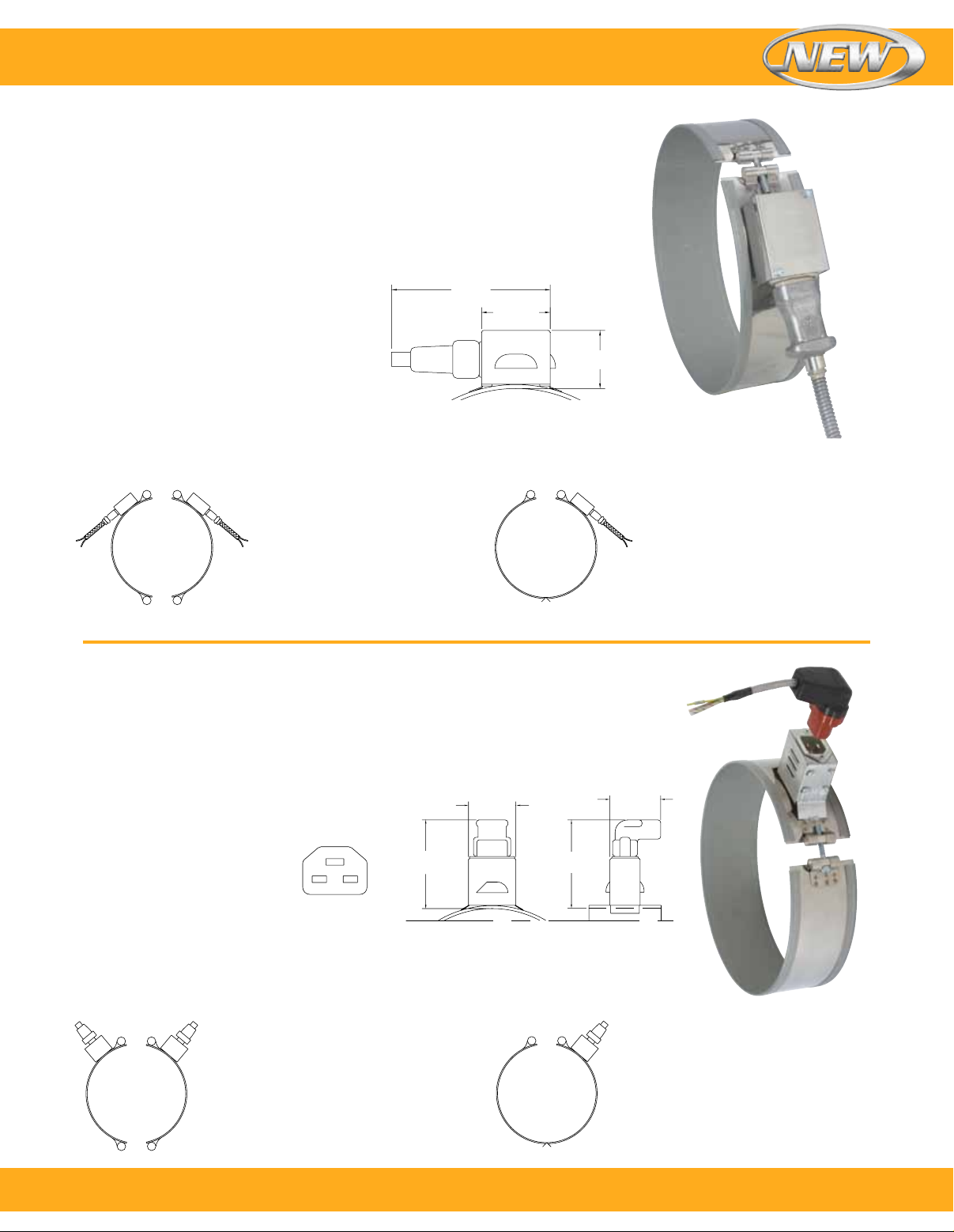
Type P2–High Temperature Quick Disconnect Plugs
Type P2—Low Profile Assembly
P2F–Low profile assembly only
P2G–with straight plug only
One-Piece Band
Standard Termination Location:
Next to gap; center of width
Minimum Inside Diameter: 76.2 mm (3")
Minimum Width: 63.5 mm (2¹⁄₂")
Plug Electrical Ratings
2-Pole 3-Wire Grounding
Maximum Volts: 250 Vac
Maximum Amps: 16 A
Maximum Temperature: 300°C (572°F)
Two-Piece Band
Standard Termination Location:
Next to same gap on each half;
center of width
Minimum Inside Diameter:
76.2 mm (3")
Minimum Width: 63.5 mm (2¹⁄₂")
P2H–with straight plug and
galvanized cable
P2J–with straight plug and stainess
steel cable
P2K–with straight plug and wire braid
5⁷⁄₈"
2⁷⁄₈"
Type P2G shown
1³⁄₄"
Type P2H shown
One-Piece Expandable Band
Standard Termination Location:
Next to gap; center of width
Minimum Inside Diameter:
76.2 mm (3")
Minimum Width: 63.5 mm (2¹⁄₂")
Type P3–DIN 49458 A/B Quick Disconnect Plugs
Type P3— Vertical Box Assembly
P3A–Box assembly only
One-Piece Band
Standard Termination Location: Next to gap;
center of width
Minimum Inside Diameter: 76.2 mm (3")
Minimum Width: 38.1 mm (1¹⁄₂")
Plug Electrical Ratings
2-Pole 3-Wire Grounding
Maximum Volts: 250 Vac
Maximum Amps: 16 A
Maximum Temperature: 200°C (392°F)
Two-Piece Band
Standard Termination Location:
Next to same gap on each half;
center of width
Minimum Inside Diameter:
76.2 mm (3")
Minimum Width: 38.1 mm (1¹⁄₂")
P3B–Box assembly with straight plug
P3C–Box assembly with right-angle
plug only
4³⁄₁₆"
Standard pin
orientation
2¹⁄₄"
2⁷⁄₁₆"
4³⁄₁₆"
Type P3C shown
One-Piece Expandable Band
Standard Termination Location:
Next to gap; center of width
Minimum Inside Diameter:
76.2 mm (3")
Minimum Width: 38.1 mm (1¹⁄₂")
To order, call 1-800-826-6342 or shop online at omega.com
SM
21
Page 22
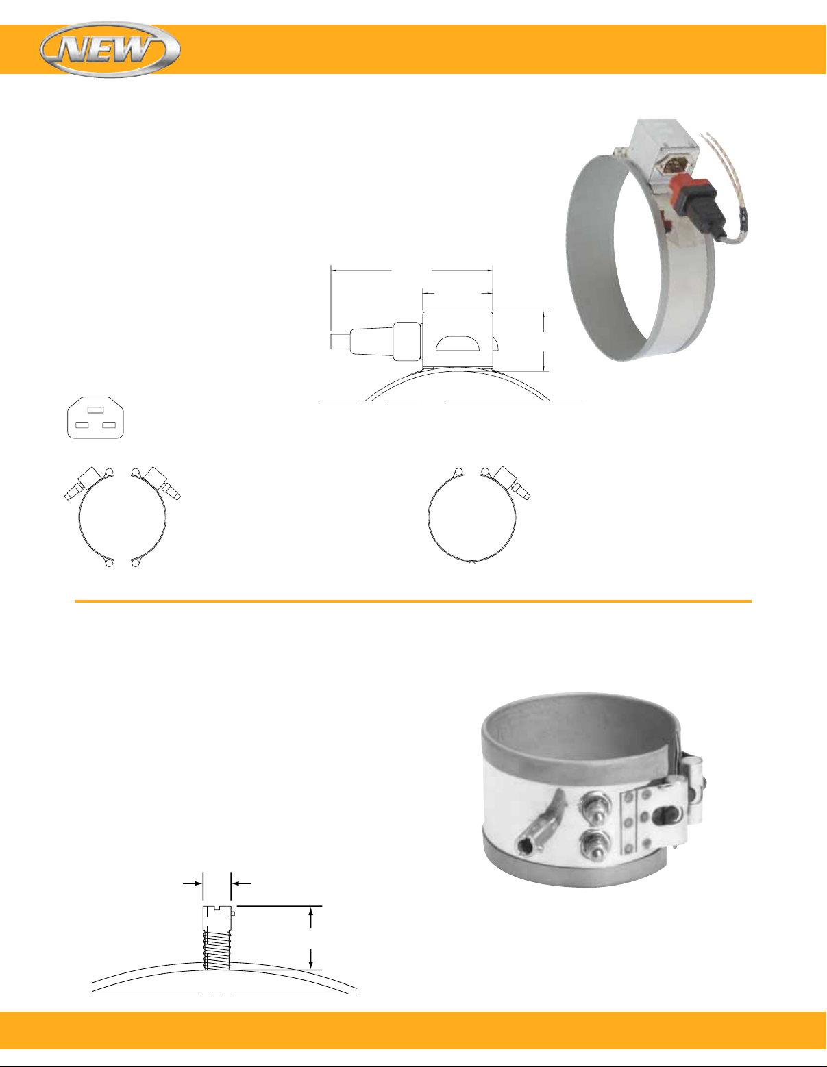
Type P4–DIN 49458 A/B Quick Disconnect Plugs
Type P4— Horizontal Box Assembly
P4A–Box assembly only
P4B–Box assembly with straight plug
One-Piece Band
Standard Termination Location: Next to gap;
center of width
Minimum Inside Diameter: 76.2 mm (3")
Minimum Width: 63.5 mm (2¹⁄₂")
Plug Electrical Ratings
2-Pole 3-Wire Grounding
Maximum Volts: 250 Vac
Maximum Amps: 16 A
Maximum Temperature: 200°C (392°F)
Standard pin orientation
Band Heaters
5⁵⁄₈"
2⁷⁄₁₆"
2¹⁄₁₆"
Two-Piece Band
Standard Termination Location:
Next to same gap on each half;
center of width
Minimum Inside Diameter:
76.2 mm (3")
Minimum Width: 63.5 mm (2¹⁄₂")
Special Duraband® Construction Options and Variations
Thermocouple Bayonet Adaptor
A standard bayonet adaptor facilitates the installation of an
external thermocouple with a standard bayonet cap. The
standard location for the adaptor is 90° from the gap.
Specify without through hole for heater sensing or with
through hole for load sensing. For heaters less than 25 mm
(1") wide order separate strap clamping and utilize the gap
for the thermocouple.
Visit omega.com for a complete selection of thermocouples.
One-Piece Expandable Band
Standard Termination Location:
Next to gap; center of width
Minimum Inside Diameter:
63.5 mm (2¹⁄₂")
Minimum Width: 76.2 mm (3")
22
⁷⁄₁₆"
⁷⁄₈"
To order, call 1-800-826-6342 or shop online at omega.com
SM
Page 23
Inside
Diameter
Outside
Diameter
Bolt
Circle
Band Heaters
Construction Options and Variations
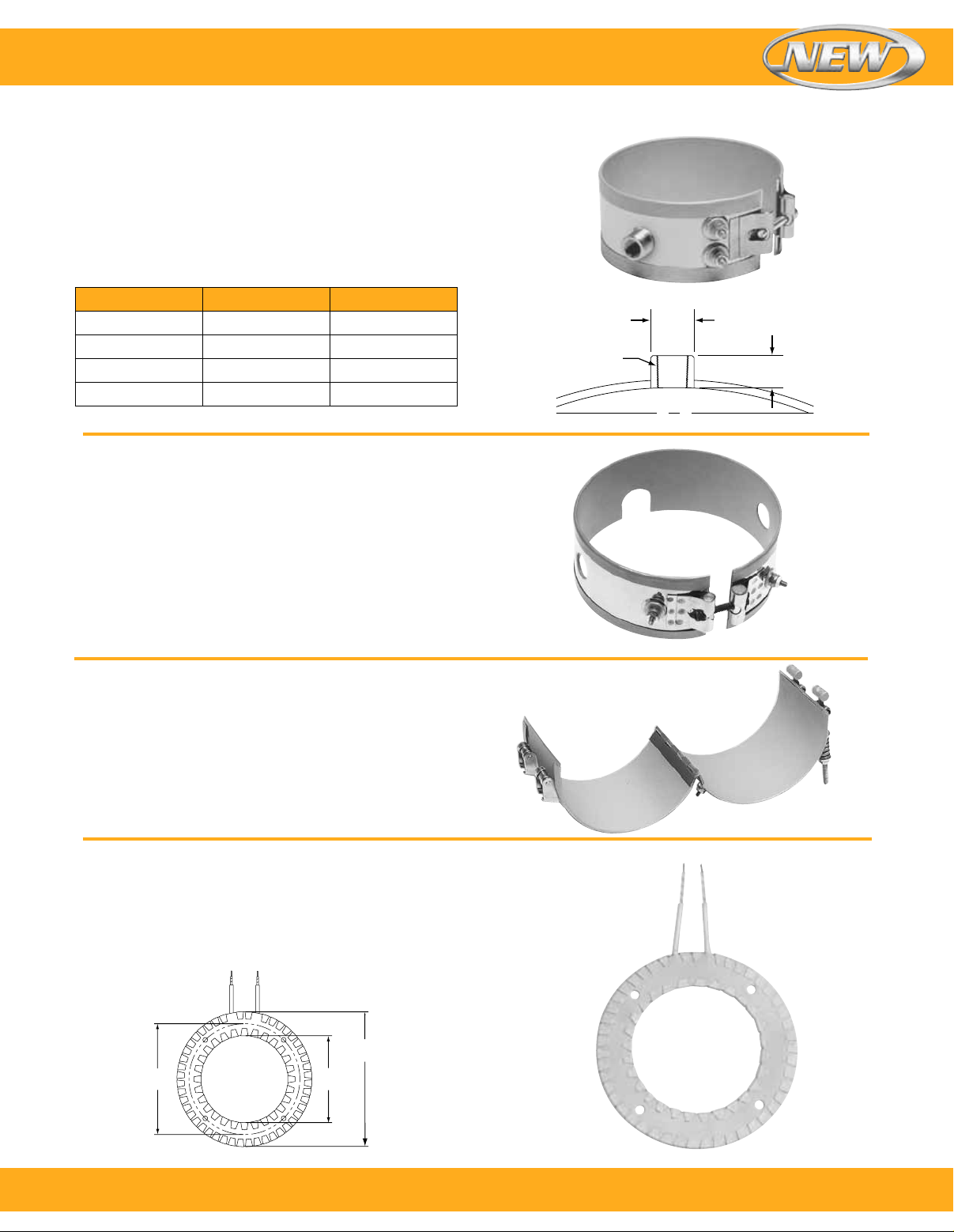
Thermocouple Coupling
The thermocouple coupling facilitates the installation of
an external thermocouple with a threaded fitting to sense
the temperature of the band. The standard location for the
coupling is 90° from the gap. Specify without through hole
for heater sensing or with through hole for load sensing.
Available Bushing Sizes
Thread D, mm (inch) H, mm (inch)
¹⁄₈-27 NPT 14.2 (⁹⁄₁₆) 15.8 (⁵⁄₈)
¹⁄₄-20 NPT 19 (³⁄₄) 17.4 (¹¹⁄₁₆)
³⁄₈-18 NPT 22.2 (⁷⁄₈) 15.8 (⁵⁄₈)
M12–1.75 mm
Holes and Cutouts
Holes and cutouts are normally required in band heaters
for clearance for thermocouple probes or holding bolts. An
oversize gap can in many cases serve the same purpose,
saving the expense of the hole.
Using the center of the gap as a starting point, specify
the location of the centerpoint of the hole or cutout in terms
of degrees and the distance from the edge of the heater.
In addition, state the size of the hole or cutout.
For critical hole and cutout locations, a detailed drawing
will be required.
Note: A minimum of 13 mm (
to the edge of the heater.
19 (³⁄₄) 12.7 (¹⁄₂)
1
") is required from the hole
⁄
2
D
NPT
H
Hinged Two-Piece Band
The hinged two-piece band heater is connected with
a continuous hinge for easy installation and removal.
This heater can be opened and closed as often as is
necessary. The preferred method of clamping is latch and
trunnion. It is available with any screw or lead variation.
When ordering, specify watts and volts each half.
Minimum Width: 34.9 mm (1³⁄₈")
Special Mica Insulated Heater Construction Variations
Ring Heaters
When ordering ring heaters, specify inside and outside
diameters. If mounting holes are required, specify location
and hole size. For critical hole and cutout locations, a
detailed drawing will be required.
To order, call 1-800-826-6342 or shop online at omega.com
SM
23
Page 24
Duraband Features
Additional Duraband® Heater Features
Electrical Variations
Three-Phase
On very high wattage band heaters it would be advantageous
to set up the wiring three-phase to reduce the current load
across a single conductor. Three-phase wiring is available
on select clamping/construction or termination variation
(termination location is subject to engineering approval).
Minimum ID: 76.2 mm (3"), Minimum Width: 50.8 mm (2")
Dual Voltage
Band heaters can be designed using 3-wire series/parallel
circuits for dual voltage applications. Whether the heater is
run on the higher or lower voltage, the wattage will be the
same. Dual Voltage wiring is available on any clamping/
construction or termination variation.
Ground Terminal or Lead
For those applications requiring a separate ground terminal
or lead attached to the heater sheath. A ground terminal
or lead is available on any clamping/construction or
termination variation.
Single Phase/Three Phase Duraband
Heaters can be designed with multiple circuits to operate
single or three-phase.
Band Heaters
Built-In Thermocouples
Heaters can be manufactured with a built-in thermocouple to
closely control the temperature of the heater.
Type J or K thermocouples are available with fiberglass, wire
braid or any other required insulation. Contact OMEGA with
your requirements.
Construction Variations
All Stainless Steel Construction
Mica band heaters can be constructed with the external
sheath made entirely from stainless steel. This allows the
Duraband to reach the maximum temperature of 650°C
(1200°F). All stainless steel construction is available on any
clamping/construction or termination variation.
Other Sheath Materials
Other sheath materials, such as rust-resistant steel,
Monel®, aluminum, or copper are also available for
unique applications.
Lead Variations
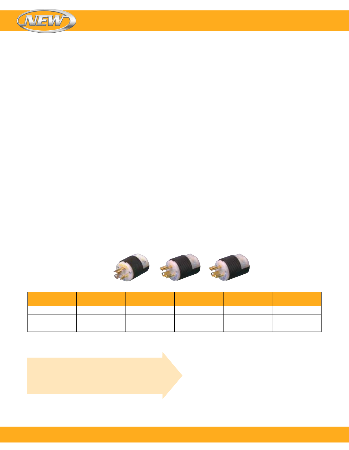
Electrical Plugs
Industry standard NEMA Twist-Lock® electrical plugs are
available. The plugs can be attached to fiberglass leads,
armor cable or wire braid. Electrical plugs can be added to
any clamping/construction or termination variation.
P4
Plug
Model No.
EHD-102-113 EHD-103-104
EHD-102-121 EHD-103-107
EHD-102-104 N/A
Receptacle
Model No.
Reference
P4 twist lock L5-15 15 125
P5 twist lock L6-15 15 250
P9 twist lock L2-20 20 250
Custom Engineered/Manufactured Heaters
Understanding that an electric heater can be very
application specific, for sizes not listed OMEGA® will
design and manufacture a Duraband Heater to meet
your requirements.
Terminal Lugs
Various types of crimp terminals can be attached to the
heater leads to make wiring into applications quick and easy.
High temperature [649°C (1200°F)] ring terminals and nylon
or PVC insulated terminals are available. Spade, ring, and
right-angle or straight quick disconnect type terminals can be
attached to the leads.
P5 P9
NEMA P or R
Amps
Volts
Please Specify the Following:
l Inside Diameter
l Width
l Wattage
l Voltage
l Quantity
l Termination (see pages
9 through 22)
l Lead Cable/Braid
Length
l Construction style
(see pages 5, 22)
l Clamping variation
(see pages 6 through 8)
l Special Features
24
To order, call 1-800-826-6342 or shop online at omega.com
SM
Page 25

Band Heaters
Installation Recommendations
Installation Accessories Available
l High Temperature Terminal Lugs
™
l Igloo
l Ul Listed Plugs
l High Temperature Lead Wire 450°C (842°F)
l Armor Cable
l Stainless Steel Braid
1. Disconnect electric power to the machine and/or heaters
2. Do not install heaters in areas where combustible gases,
3. Use as many narrow band heaters as the application will
4. Using a heater that closely matches the wattage
5. Make certain that all barrel surfaces are clean and have a
6. Expandable type Mica Band Heaters may be opened
Caution: Do not open one-piece non-expandable type mica band
7. Position heater bands on the barrel.
8. Securely tighten heater bands around the barrel.
9. For heaters with screw terminals, remove the top nut
10. All electrical wiring of heater bands should be done by a
A. Use only Stainless Steel or other high temperature lugs
Caution: Do not use copper or plated copper lugs.
B. Use only lead wire with high temperature insulation and
Ceramic Terminal Covers
prior to installing or replacing heaters.
vapor or dust is present.
permit. 38 through 76 mm (1¹⁄₂ through 3") wide heaters
are recommended.
requirements will decrease the frequency of cycling and
temperature overshoot, thereby increasing the life of
the heater.
smooth finish. Any contaminants or imperfections on the
surface can cause premature heater failure.
once at the gap to fit on the barrel. Do not open these
heaters beyond their specified heater diameter.
heaters. Opening of these heaters can damage Mica
Insulation and will create electrical short circuits.
Clamping force must be equally distributed on heaters
with more than one set of clamping brackets.
Recommended clamping bolt torque is 10 ft./lbs.
and flat washers from the power screw terminals. Do not
remove or loosen the bottom nut on the power screw
terminals. The bottom nut is tightened to 60 in./lbs. at the
factory. A loose bottom nut may cause premature
heater failure.
qualified electrician.
to prevent material degradation when exposed to high
temperatures over a prolonged period of time.
proper gauge size.
l High Temperature Sleeving
l Stainless Steel Barrel Covers
l High Temperature Mica Insulated Wiring Harnesses
450°C (842°F)
l Thermocouples
l Temperature Controllers
l High Temperature Fiberglass Tape
C. When connecting power leads to screw terminals make
certain that barrels of terminal lugs are not facing down
toward the heater case, which will create a short circuit.
Tighten the top nut to 30 in/lbs.
D. Make certain power lead wires do not make contact
with hot heater surface to avoid degradation of lead
wire, as this can cause electrical short circuits.
E. Make sure the voltage input to the heater bands does
not exceed the voltage rating that is stamped on the
heater band.
F. It is recommended that an amperage reading is taken
for each heater to verify proper wiring.
(Amps = Watts/Volts)
11. Insulate all live electrical wires per applicable safety
standards.
12. Begin heater band re-tightening procedure. Be sure to
wear protective gloves.
A. Energize heater bands and allow the heater to reach
149°C (300°F). This usually takes between 3 and
5 minutes.
B. Turn off power and immediately re-tighten the heater
bands to 10 ft./lbs. Turn power back on.
13. Install shrouds around the machine to meet applicable
safety requirements.
14. Once installed, check surroundings to make sure that
contaminants won’t get on the heater while the unit is in
operation. Accumulation of contaminants on heaters can
cause premature heater failure.
15. Insulating blanket installations must have band heater
retightening sequence (#12) completed before blanket
installation. Lead wires must exit the insulation blanket
as soon as possible; do not entrap lead wires between
heater sheath and insulation blanket.
Caution: It is imperative that upon start-up of new machines at
customer facilities, all of the aforementioned parameters
are double checked by qualified field service personnel.
CAUTION: Exposed electrical wiring on band
heater installations is a violation of Electrical
Safety Codes including O.S.H.A.
To order, call 1-800-826-6342 or shop online at omega.com
SM
25
Page 26
Band Heaters
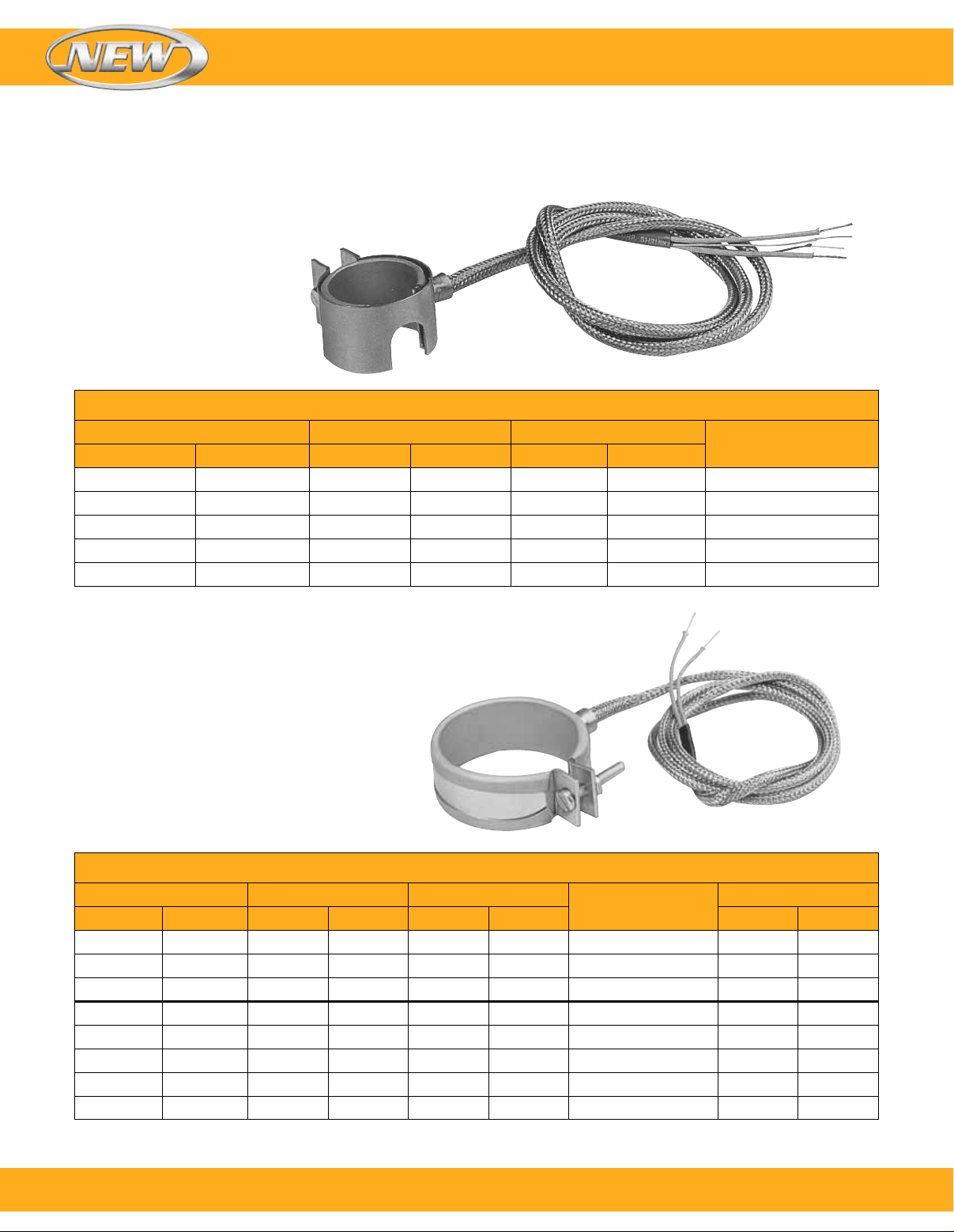
Nozzle Band Heaters
Standard Replacement Mica Insulated Band Heaters for Plastic Injection Molding Machines
To Order Visit omega.com/mbh_nozzle for Pricing and Details
Model Number Inside Diameter Width
Watt120V 240V mm inch mm inch
— MBH00033
MBH00031 MBH00035
— MBH00036*
— MBH00038
— MBH00039*
31.8 1
38.1 1
38.1 1
58.7 2
58.7 2
* Heaters have built-in Type J thermocouple.
Ordering Example: MBH00031, 120V, 150 watt, nozzle band heater.
1
⁄4 30.2 13⁄16 125
1
⁄2 25.4 1 150
1
⁄2 25.4 1 150
5
⁄16 36.5 17⁄16 300
5
⁄16 36.5 17⁄16 300
To Order Visit omega.com/mbh_nozzle for Pricing and Details
Model Number Inside Diameter Width
120V 240V mm inch mm inch Watt/cm
MBH00030 MBH00034
MBH00003 MBH00012
MBH00004 MBH00013
MBH00005 —
— MBH00037
MBH00006 MBH00014
MBH00007 MBH00015
MBH00009 MBH00016
Ordering Example: MBH00007, 120V, 200 watt, nozzle band heater.
26
To order, call 1-800-826-6342 or shop online at omega.com
38.1 1
44.5 1
50.8 2 25.4 1 200 5.9 38
57.2 2
57.2 2
63.5 2
76.2 3 25.4 1 200 3.7 24
88.9 3
1
⁄2 25.4 1 150 6.3 40
3
⁄4 25.4 1 175 6.0 39
1
⁄4 25.4 1 175 4.5 29
1
⁄4 38.1 11⁄2 300 5.1 33
1
⁄2 25.4 1 250 5.7 36
1
⁄2 25.4 1 300 4.7 30
Watt
Watt Density
2
Watt/in
2
SM
Page 27
Band Heaters
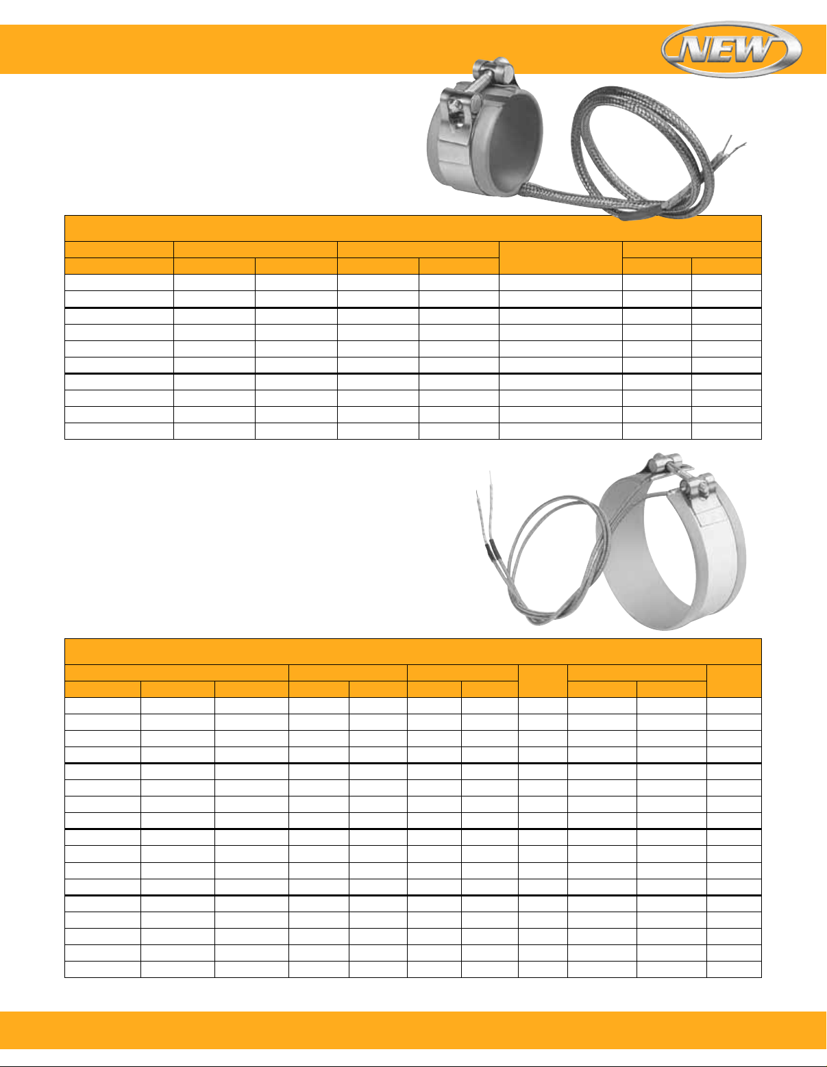
Nozzle Band Heaters
Standard Replacement Mica Insulated Band
Heaters for Plastic Injection Molding Machines
To Order Visit omega.com/mbh_nozzle for Pricing and Details
Model Number Inside Diameter Width
240V mm inch mm inch Watt/cm2Watt/in
MBH00019
MBH00020
MBH00021
MBH00022
MBH00023
MBH00024
MBH00025
MBH00026
MBH00027
MBH00028
All heaters have 609 mm (24") high temperature leads with 559 mm (22") stainless steel overbraid.
Ordering Example: MBH00023, 240V, 600 watt, nozzle band heater.
38.1 1
38.1 1
38.1 11⁄2 63.5 21⁄2 400 6.7 43
38.1 11⁄2 76.2 3 450 6.3 40
38.1 11⁄2 114.3 41⁄2 600 5.6 36
44.5 1
54.0 21⁄8 23.8
58.7 2
58.7 2
69.9 2
1
⁄2 38.1 11⁄2 275 7.7 49
1
⁄2 44.5 13⁄4 250 6.0 38
3
⁄4 152.4 6 800 4.6 30
¹⁵⁄₁₆
5
⁄16 23.8
5
⁄16 34.9 13⁄8 240 4.3 28
3
⁄4 38.1 11⁄2 260 3.5 23
¹⁵⁄₁₆
Watt
215 6.3 40
260 6.9 44
Watt Density
2
Design Features
l All Heaters Have 609 mm (24") High Temperature Leads
with 559 mm (22") Stainless Steel Overbraid—Type W3
l Heaters Less Than 38 mm (1¹⁄₂") Wide Have Separate
Straps—Type SE
l Designed as One-Piece Expandable Type, Enables You
to Open Up the Heater to the Diameter of the Barrel for
Easy Installation
To Order Visit omega.com/mbh_nozzle for Pricing and Details
Ordering Example:
MBH00040 — —
MBH00041 MBH00054 —
MBH00042 MBH00055 —
MBH00043 MBH00056 —
MBH00044 MBH00057 —
MBH00045 MBH00058 —
MBH00046 MBH00060 —
MBH00047 — —
MBH00048 MBH00062 MBH00066
MBH00049 — —
MBH00050 MBH00063 MBH00067
MBH00051 — —
MBH00052 — —
MBH00053 MBH00065 MBH00069
Ordering Example: MBH00049, 120V, 500 watt, nozzle band heater.
Model Number Inside Diameter Width
3
69.9 2
⁄4 88.9 31⁄2 600 3.5 22 NE
76.2 3 25.4 1 200 3.7 24 SE
76.2 3 25.4 1 250 4.7 30 SE
76.2 3 25.4 1 300 5.6 36 SE
76.2 3 25.4 1 400 7.4 48 SE
76.2 3 38.1 1
— MBH00059 —
76.2 3 63.5 2
1
88.9 3
⁄2 15.9
88.9 31⁄2 25.4 1 200 3.1 20 SE
— MBH00061 —
88.9 3
1
⁄2 38.1 11⁄2 500 5.2 33 NE
101.6 4 50.8 2 625 4.2 27 NE
101.6 4 76.2 3 500 2.2 14 NE
101.6 4 101.6 4 1250 4.2 27 NE
1
⁄2 25.4 1 300 3.5 23 SE
1
⁄2 101.6 4 700 2.1 13 NE
— MBH00064 MBH00068
114.3 4
114.3 41⁄2 50.8 2 700 4.1 27 NE
114.3 4
114.3 41⁄2 101.6 4 1400 4.1 27 NE
1
⁄2 500 6.1 40 NE
1
⁄2 300 2.2 14 NE
5
⁄8 200 5.0 32 SE
Watt
Watt Density
2
Watt/in
2
Style120V 240V 480V mm inch mm inch Watt/cm
To order, call 1-800-826-6342 or shop online at omega.com
SM
27
Page 28
Nozzle Band Heaters
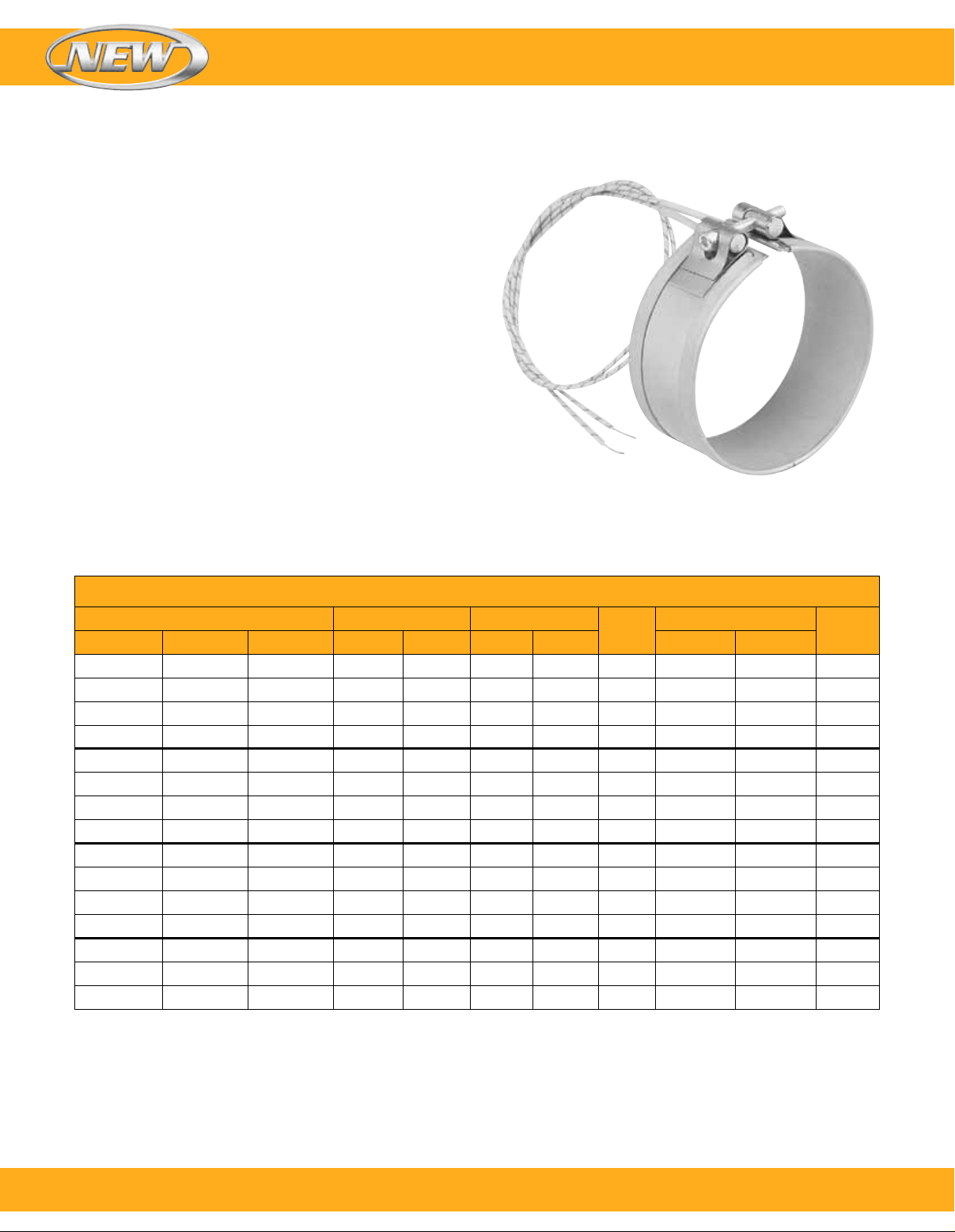
Standard Replacement Mica Insulated Band
Heaters for Plastic Injection Molding Machines
Design Features
l All Heaters Have 0.61 m (24") High Temperature
Leads—Type L2
l Heaters Less Than 38 mm (1¹⁄₂") Wide Have Separate
Straps—Type SE
l Designed as One-Piece Expandable Type, Enables You
to Open Up the Heater to the Diameter of the Barrel for
Easy Installation
Band Heaters
To Order Visit omega.com/mbh_nozzle for Pricing and Details
Model Number Inside Diameter Width
MBH00070 MBH00078 —
MBH00071 MBH00079 —
MBH00072 MBH00080 —
MBH00073 MBH00081 —
MBH00074 MBH00082 —
MBH00075 MBH00083 —
MBH00076 MBH00084 —
MBH00077 MBH00085 —
— MBH00086 —
— MBH00087 MBH00093
— MBH00088 —
— MBH00089 MBH00094
— MBH00090 MBH00095
— MBH00091 MBH00096
— MBH00092 MBH00097
Ordering Example: MBH00085, 240V, 500 watt, nozzle band heater.
76.2 3 25.4 1 200 3.7 24 SE
76.2 3 25.4 1 250 4.6 30 SE
76.2 3 25.4 1 300 5.5 36 SE
76.2 3 25.4 1 400 7.4 47 SE
1
76.2 3 38.1 1
76.2 3 38.1 1
76.2 3 38.1 1
⁄2 400 4.9 32 NE
1
⁄2 450 5.5 36 NE
1
⁄2 500 6.1 40 NE
76.2 3 50.8 2 500 4.6 30 NE
1
88.9 3
88.9 3
88.9 3
125.4 4
139.7 5
149.2 5
190.5 7
⁄2 25.4 1 400 6.2 40 SE
1
⁄2 38.1 11⁄2 250 2.6 17 NE
1
⁄2 50.8 2 650 5.0 33 NE
15
⁄16 63.5 21⁄2 720 3.1 20 NE
1
⁄2 63.5 21⁄2 950 3.6 23 NE
7
⁄8 38.1 11⁄2 675 4.0 26 NE
1
⁄2 38.1 11⁄2 1000 4.6 30 NE
Watt
Watt Density
2
Watt/in
2
Style120V 240V 480V mm inch mm inch Watt/cm
28
To order, call 1-800-826-6342 or shop online at omega.com
SM
 Loading...