

Page 1
1
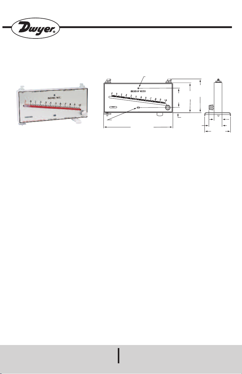
5/64 [5.95] x 13/32 [10.32] MOUNTING SLOT
1
0-5/8 [269.88]
5
-5/16
[134.95]
M
AX
4
-5/8
[117.48]
2-31/32
[
75.41]
25/32
[
19.84]
Ø15/64 [5.95] MOUNTING HOLE
1
-1/4
[
31.75]
2
-1/4 [57.15]
MAX
4
[101.60]
MARK II MODEL 40
Bulletin D-59
Mark II - Model 40 Molded Plastic Manometers
Installation and Operating Instructions
Dwyer Mark II - Model 40 Molded Plastic
Manometers are ideally suited for air velocity
and air filter gage applications at minimal cost.
These inclined manometers provide linear
calibration and excellent resolution throughout
their ranges. They are capable of pressure
measurements above and below atmospheric,
as well as differential pressure measurements.
INSTALLATION
Stationary Applications: Mount the Mark II
manometer on a convenient vertical surface.
The installation should not be exposed to strong
chlorine atmospheres or solvents such as
benzene, acetone, carbon tetrachloride, etc. The
instrument is suitable for total internal pressures
of up to 15 psi (100 kPa) and ambient
temperatures of 150°F (65°C). DO NOT
EXCEED THESE LIMITS. At the mounting
location selected, drill two 9/64˝ diameter holes
on a vertical line spaced 2-31/32˝ apart. Install
the gage with the self-tapping screws provided,
turning the screws down snug but not tight.
Adjust the position of the gage until the bubble is
centered in the spirit level. Tighten the mounting
screws, checking to be sure the instrument
remained level, and re-level as necessary.
SPECIFICATIONS
Accuracy: ±3% of full scale.
Maximum Internal Working Pressure: 15 psi
(100 kPa).
Maximum Working Temperature: 150°F
(65°C).
Scale Length: Approx. 8-1/4˝ (21 cm).
Weight: 10 oz (283.49 g).
ACCESSORIES
1 oz. gage fluid, mounting screws, 1/8˝ NPT
tubing adapters, washers, nuts, red and green
pointer flags, (2) 4-1/2 ft. lengths 3/16˝ I. D.
vinyl tubing.
DWYER INSTRUMENTS, INC.
Phone: 219/879-8000 www.dwyer-inst.com
Page 2
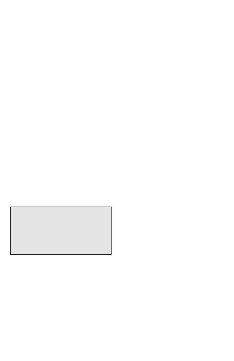
Portable Applications: For portable use, a
molded plastic swing-away foot and leveling
screw are provided. Referring to the picture on
the first page of this bulletin, secure the swingaway foot to the bottom of the gage, using the
plastic screw in the tapped hole on the righthand side. Install the plastic leveling screw in the
tapped hole on the bottom left side of the
manometer. In use, the swing-away foot is
positioned perpendicular to the gage. With the
manometer in operating position, the leveling
screw is adjusted until the bubble is centered in
the spirit level. For storage, the swing-away foot
can be rotated to a position in line with the gage
body.
FILLING
Turn the zero adjust knob fully counterclockwise
until it stops; then turn it clockwise
approximately four full turns so as to center the
adjustment to allow room for adjusting either
side of zero. Unscrew the entire low pressure
(right) shut-off connection fitting. A 3/4˝ wrench
is required. Also, remove the cork, disc, and “O”
ring. Vent the left connector by turning the elbow
1 - 2 turns counterclockwise. Slowly fill gage
with fluid provided until fluid rises in the
indicating tube to the vicinity of zero on the
scale. Nearly all the fluid provided will be
required to fill the gage. Replace the cork, disc,
“O” ring and the low-pressure shut-off
connection fitting.
OPERATION
The Model 40 manometer is provided with
convenient shut-off tubing connections to
prevent loss of fluid when transporting the gage.
To use the gage, turn each barbed tubing
connection counterclockwise 1-2 turns from the
closed (fully clockwise) position. Rotate the zero
adjustment for an exact zero reading and the
gage is ready for use. In stationary installations,
these steps need only be performed upon initial
installation. In portable use, each time the gage
is used the connections must be opened, the
gage leveled and zeroed; prior to storage, the
gage connections must be closed.
Pressure Connection: Two 4-1/2˝ lengths of
plastic tubing are included with the gage along
with two adapters for connection of the tubing to
1/8˝ NPT fittings or sheet metal ducts. The
tubing from the high pressure pickup should be
connected to the high pressure (left) barbed
connection at the top of the gage. The tubing
from the low pressure pickup should be
connected to the low pressure (right) barbed
fitting. Stick-on red and green arrows are
provided to indicate the appropriate range of
readings for the particular application. The 1/8˝
NPT tubing adapters can be used as static
pressure sensors in sheet metal ducts by drilling
a 7/16˝ diameter hole in the duct and mounting
the adapter in the hole, placing one of the
washers on each side of the duct wall and
securing the 1/8˝ NPT nut.
CAUTION
USE .826 SPECIFIC GRAVITY RED GAGE
FLUID FOR MODEL #’S 40-1, 40-1-AV, 40250 Pa, 40-250 Pa-AV, and 40-25 mm. Use
1.910 SPECIFIC GRAVITY BLUE GAGE
FLUID FOR MODEL #’S 41-2, 41-2-AV, 41600 PA, 41-60 mm.
TYPICAL APPLICATIONS
Draft Gage: Run iron pipe, 1/8˝ or larger in size,
from the source of the draft to a point within 41/2˝ of the manometer. Provide a means for
periodic clean-out to remove any soot
accumulation. Using one of the lengths of tubing
provided, make the connection from the pipe to
the low pressure (right) fitting on the gage.
Page 3

Static Pressure Indicator: Using the 1/8˝ NPT
tubing adapters provided, make a static pressure
connection to the duct at the desired location.
Using either the tubing provided or a longer
length if necessary, connect the pressure sensor
to either the high (left) or low (right) pressure
connection of the gage, depending on whether
the static pressure is positive or negative
compared to atmosphere. Where air velocities in
the duct are 1000 ft. per minute or higher, static
pressure error may be induced unless a static
pressure tip is used.
Air Filter Gage: Mount the gage within 4-1/2˝ of
the filter bank and install a 1/8˝ NPT tubing
adapter in the duct on each side of the filter
element. Run the tube from the fitting on the
discharge side of the filter to the low pressure
(right) gage connection and the tube from the
upstream side of the filter to the high pressure
(left) connection. Remove the paper backing
from the green and red arrows and install the
arrows on the face of the manometer adjacent to
the indicating tube to indicate clean and dirty filter
readings.
Air Velocity Indicator: A pitot tube is required for
air velocity readings and care must be taken in
installations to insure accuracy. Select a location
for the pitot tube with smooth straight sections of
duct at least 8-1/2 diameters upstream and 1-1/2
or more diameters downstream. Install the pitot
tube so it is centered in the duct with the tip
directed into the air stream. The right angle pitot
tube connection is connected to the low pressure
(right) gage connection. The straight pitot tube
connection is connected to the high pressure
(left) gage connection. Velocity reading now
indicated on the gage is the center or maximum
air velocity in the duct. For average velocity
across the full area of the duct, multiply by a
factor of .9. The velocity indicated is for dry air at
70°F (21.1°C), 29.9˝ barometric pressure, and a
resulting density of .075 pounds per cubic foot.
For variations from these standard conditions,
corrections may be based upon the following
formula:
Air Velocity (FPM) = 1096.7
Where Pv = velocity pressure in in./H2O
D = air density in lbs. per ft
D = 1.325 x
Pb
T
Pv
D
3
Where Pb = barometric pressure in inches of
mercury
T = absolute temperature (indicated °F
+ 460)
To determine the volume of air flow in the duct in
cubic feet per minute, multiply air velocity in FPM
times the cross-sectional area of the duct in
square feet.
Page 4
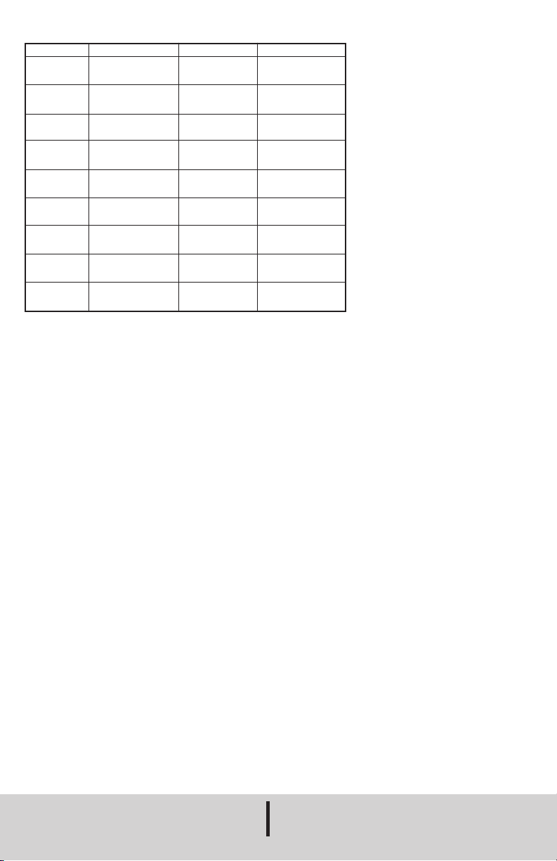
OPERATING RANGES
Model
40-1
40-1-AV*
41-2
41-2-AV*
40-250 Pa
40-250-AV*
41-600 Pa
40-25 mm
41-60 mm
Range
.10-0-1.00˝ w.c.
0-1.10˝ w.c.
0-4200 fpm
.20-0-2.400˝ w.c.
0-2.50˝ w.c.
0-6300 fpm
10-250 Pa
0-260 Pa
0-21 mps
20-0-600 Pa
0-26 mm w.c.
0-60 mm w.c.
Minor Grades
.01˝ w.c.
.01˝ w.c.
varies
.02˝ w.c.
.02˝ w.c.
varies
2 Pa
2 Pa
varies
5 Pa
2 mm w.c.
5 mm w.c.
* Pitot tube required at additional cost.
Indicating Fluid
.826 sp. gr.
(red fluid)
.826 sp. gr.
(red fluid)
1.910 sp. gr.
(blue fluid)
1.910 sp. gr.
(blue fluid)
.826 sp. gr.
(red fluid)
.826 sp. gr.
(red fluid)
1.910 sp. gr.
(blue fluid)
.826 sp. gr.
(red fluid)
1.910 sp. gr.
(blue fluid)
©Copyright 2015 Dwyer Instruments, Inc. Printed in U.S.A. 8/15 FR# 440433-00 Rev. 5
DWYER INSTRUMENTS, INC.
Phone: 219/879-8000 www.dwyer-inst.com
 Loading...