

Page 1
Bulletin V-30
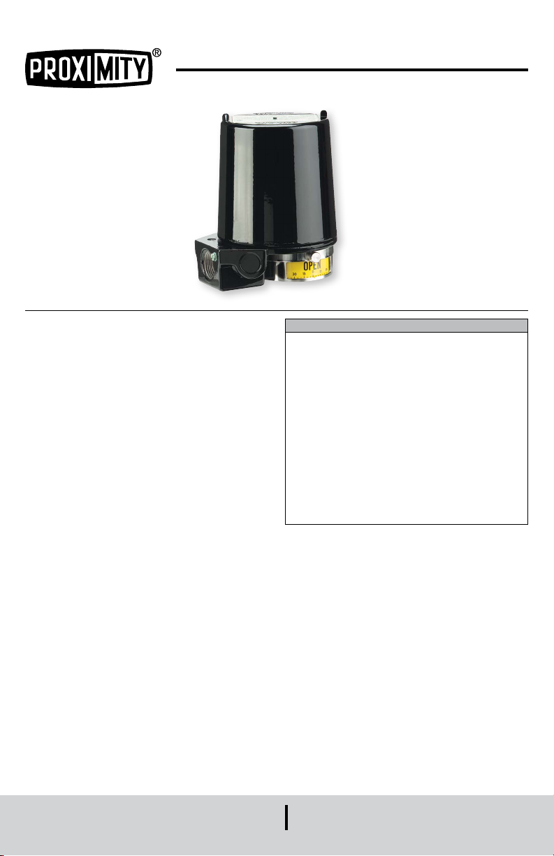
Series Mark Position Indicator/Transmitter
Specications - Installation and Operating Instructions
INTRODUCTION
The Proximity Controls Series Mark Position
Indicator/Transmitter is a line of position indicators
with a selection of various output options. Three model
styles make up the Mark Series to cover almost any
application. A magnetic drive that completely seals the
switch compartment from the atmosphere for maximum
leak protection is utilized in the Mark 1. The Mark 3 uses
the same magnetic drive of the Mark 1, but it can be used
for multi-turn applications with 1 to 25 revolutions, such
as gate valves. A through shaft drive is incorporated in
the Mark 4 making the unit a lower cost alternative to the
Mark 1 for applications that are not as demanding.
Standard models in the Mark Series have visual position
indicators and are weatherproof, ameproof, and
submersible. A large variety of outputs are available to
t specic applications. There is a choice of 1 to 6 switch
outputs of 13 varieties including inductive sensors,
high temperature switches, gold contact switches,
hermetically sealed switches, and high current switches.
Aside from switch outputs, the Mark Series offers
potentiometer outputs, 4-20 mA transmitters, and HART
communication.
The units are purchased for either direct drive
applications, such as rotary valves, or lever drive
applications, such as linear valves. For the Mark 1, 3,
and 4 this instruction manual starts with installation of
the unit to the device being monitored, and the set up
of switch models. Separate instructions follow covering
the potentiometer and transmitter set up if your unit has
those options.
This product uses FreeRTOS (www.FreeRTOS.org)
version 8.0.1. A copy of the original FreeRTOS source
shall be provided upon request.
®
TABLE OF CONTENTS
Introduction. . . . . . . . . . . . . . . . . . . . . . 1
Dimensions . . . . . . . . . . . . . . . . . . . . . 2
Specications . . . . . . . . . . . . . . . . . . . 2-3
Model Number Conguration. . . . . . . . . . . . 4-5
Junction Package . . . . . . . . . . . . . . . . . . 6
Factory Sealed Leads . . . . . . . . . . . . . . . . 6
Mounting Kits for Valves . . . . . . . . . . . . . . . 6
Mark 1 and 4 Direct Drive Installation . . . . . . . . 7
Mark 1 and 4 Lever Drive Installation . . . . . . . . 8
Mark 3 Direct and Lever Drive Installation . . . . . . 9
Mark 1, 3, and 4 with Potentiometer Installation . . 10
Mark 1, 3, and 4 with Transmitter Installation . . 11-12
Mark 1, 3, and 4 Transmitter with
®
Communication Protocol . . . . . . . . .12-13
HART
Wiring, Intrinsic Safety and Warnings . . . . . . 14-15
Schematics: General and Intrinsic Safety . . . . 16-19
Maintenance . . . . . . . . . . . . . . . . . . . . 20
DWYER INSTRUMENTS, INC.
P.O. BOX 373 • MICHIGAN CITY, INDIANA 46360, U.S.A.
1
Phone: 219-879-8000
Fax: 219-872-9057
dwyer-inst.com
e-mail: [email protected]
Page 2
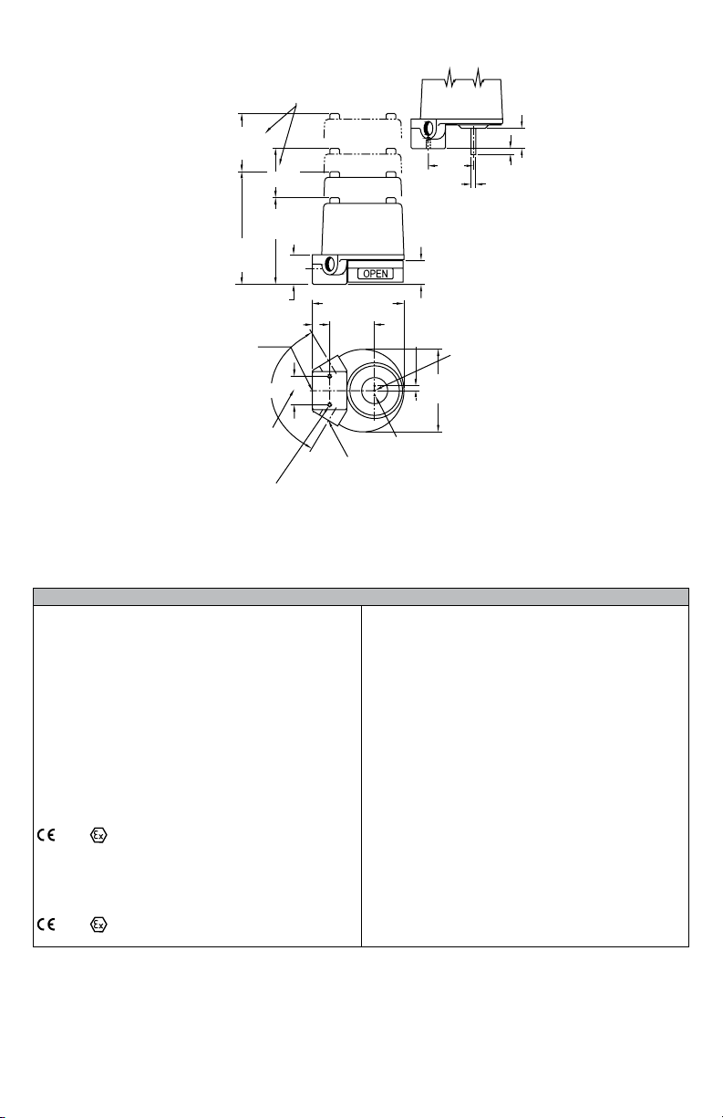
DIMENSIONS
CLEARANCE REQUIRED
FOR COVER REMOVAL
4-1/4
[107.95]
DIRECT
DRIVE
CONNECTION
OR OPTIONAL
SPECIFICATIONS
General
Product Ratings: Weatherproof and ameproof. NEMA
1, 2, 3, 3R, 3S, 4, 4X, 6, 7, 9, 12, 13.
UL rated: Class I, Div. 1 and 2, Groups B, C, D (Some
units available for Group A, consult factory); Class II,
Div. 1 and 2, Groups E, F, and G.
CSA rated: Class I, Div. 1 and 2, Groups A, B, C, D;
Class II, Div. 1 and 2, Groups E, F, and G. Submersible
to 15 meters (IP68); It is up to the end user to source the
proper ttings to ensure a watertight seal.
ATEX Compliant:
-B sufx: Directive 2014/34/EU, KEMA 03ATEX2391 X,
2813 II 2G Ex db IIC T6 Gb for -25°C/-40°C/-50°C
≤ Tamb ≤ 63°C depending on output and switch type
selected. Compliant per EN 60079-0:2012+A11:2013
and EN 60079-1:2014.
-IS sufx: Directive 2014/34/EU, KEMA 03ATEX1392 X,
2813 II 1G Ex ia IIC T4 Ga. Compliant per EN
60079-0:2012 + A11: 2013 and EN 60079-11:2012.
3 [76.20]
*4-9/16
[115.89]
5-15/16
[150.81]
1-9/16 [39.69]
1 [25.40]
3/4 NPT
CONDUIT
118°
M25 X 1.5
1-1/2
[38.10]
1/4-20 UNC THREAD
X 7/16 [11.11] DP
TYP 2 PLACES
4-7/8 [123.83]
2-3/8
[60.33]
1/2 NPT CONDUIT CONNECTION [OPTIONAL]
OR OPTIONAL M20 X 1.5 2 PLACES
*FOR MODELS 11, 12, 41 & 42
LEVER
DRIVE
2-3/8
[60.33]
.249 ± .001
[6.32 ± .03]
1-1/4 [31.75]
1/4
[6.35]
TYP
Ø4-7/16
[112.71]
Ø1/8 [3.18] PIN TYP 2 PLACES
IECEx Compliant:
-IE sufx:IECEx DEK 11.0056X Ex db IIC T6 Gb for
-25°C/-40°C/-50°C ≤ Tamb ≤ 63°C depending on output
and switch type selected. Compliant per IEC 600790:2011 and IEC 60079-1:2014.
-II sufx: IECEx DEK 11.0061X Ex ia IIC T4 Ga.
Compliant per IEC 60079-0:2011, IEC 60079-11:2011,
and IEC 60079-26:2014.
Electrical Connections: Screw terminal. Optional
factory sealed leads that are 36˝ (914.4 mm) of 16 AWG.
Conduit Connection: Standard: one 3/4˝ female NPT;
optional one to two 1/2˝ female NPT; Optional: M25 X
1.5 or M20 X 1.5 connections may be supplied in lieu of
3/4˝ and 1/2˝ female NPT for all models.
Mounting Orientation: Not position sensitive.
Weight: 4 to 6 lb (1.5 to 3.0 kg).
Operational Life: Over 10,000,000 cycles.
Maximum Altitude: 2000 meters. 5000 meters for
models 1, 3 & 4 followed by 1, 2, 4 or 6
followed by A, B, C, G, I, T, V or W.
5/16 [7.94]
#6-32 UNC
THREAD
X 1/4 [6.35]
DEEP
1-1/16
[26.99]
2
Page 3

Mark 1, 3 and 4 with Switch Outputs
Temperature Limits: -58 to 176°F (-50 to 80°C). Switch type C rated to 350°F (176°C) for 600 hours, Switch type T
rated to 250°F (121°C) continuous. (ATEX ameproof, -B sufx and IECEx ameproof, -IE sufx, rated -58 to 145°F
(-50 to 63°C) for switch type A, G, H, T, or M, -40 to 145°F (-40 to 63°C) for switch type O, R, S, V, or W, -13 to
145°F (-25 to 63°C) for switch type B, D, I, or AS interface; ATEX intrinsically safe, -IS sufx and IECEx intrinsically
safe, -II sufx, rated -13 to 104°F (-25 to 40°C) for switch type D or I, -40 to 104°F (-40 to 40°C) for switch type R, V,
or W, or -58 to 104°F (-50 to 40°C) for switch type A, G, or H).
Switch Type: See model chart on pages 4 and 5.
Electrical Rating: See model chart on pages 4 and 5.
Set Point Adjustment: Mark 1 and 4: 5 to 360°. Mark 3: 1 to 25 revolutions.
Mark 1, 3, and 4 with Potentiometer
Accuracy: ± 0.5% of FS. Optional ± 0.25% of FS.
Temperature Limits: -40 to 176°F (-40 to 80°C).(ATEX ameproof, -B sufx and IECEx ameproof, -IE sufx, rated
-40 to 145°F (-40 to 63°C) for switch types A, G, M, O, R, S, T, V, or W, -13 to 145°F (-25 to 63°C) for switch types B,
D, or I.; ATEX intrinsically safe, -IS sufx and IECEx intrinsically safe, -II sufx, rated -13 to 104°F (-25 to 40°C) for
switch type I, -40 to 104°F (-40 to 40°C) for switch types O, R, S, V, or W.
Power Rating: 1.5 watt maximum.
Output Signal: 1000 Ω standard. Optional 2000, 5000, 10000, or 20000 Ω.
Zero and Span Adjustments: Span trim pot with 2000Ω adjustment. No zero adjustment.
Rotational Travel: Mark 1 and 4: Minimum: 0°, Maximum: 340°. Mark 3: 0 to 10 revolutions.
Mark 1, 3, and 4 with Transmitter
Accuracy: ± 0.5% of FS. Optional ± 0.25% of FS.
Temperature Limits: -40 to 176°F (-40 to 80°C). (ATEX ameproof, -B sufx and IECEx ameproof, -IE sufx, rated
-40 to 145°F (-40 to 63°C) for switch types A, G, M, O, R, S, T, V, or W, -13 to 145°F (-25 to 63°C) for switch types B,
D, or I.; ATEX intrinsically safe, -IS sufx and IECEx intrinsically safe, -II sufx, rated -13 to 104°F (-25 to 40°C) for
switch type I, -40 to 104°F (-40 to 40°C) for switch types O, R, S, V, or W).
Power Requirements: 5-30 VDC.
Current Consumption: 50 mA.
Output Signal: 4-20 mA.
Zero and Span Adjustments: Trim pots for adjusting both. Mark 1 and 4: Span is adjustable from 50 to 300°. Mark
3: Span is adjustable from 1.5 to 8.5 revolutions.
Conduit Connection: 3/4˝ female NPT standard. Optional one or two 1/2˝ female NPT. M25 X 1.5 and M20 X 1.5
optional.
Rotational Travel: Mark 1 and 4: Minimum: 50°, Maximum: 300°. Mark 3: Minimum: 1.5 revolutions; Maximum: 8.5
revolutions.
®
Mark 1 and 4 Transmitter with HART
Accuracy: ± 0.5% of FS. Optional ± 0.25% of FS.
Communication
Temperature Limits: -40 to 176°F (-40 to 65°C). (ATEX ameproof, -B sufx and IECEx ameproof, -IE sufx, rated
-40 to 145°F (-40 to 63°C) for switch types A, G, M, O, R, S, V or W, -13 to 145°F (-25 to 63°C) for switch types B,
D or I; ATEX intrinsically safe, -IS sufx and IECEx intrinsically safe, -II sufx, rated -40 to 104°F (-40 to 40°C) for
switch types O, R, S, V or W; -13 to 104°F (-25 to 40°C) for switch type I).
Power Requirements: 8-30 VDC.
Current Consumption: 21 mA.
Output Signal: 4-20 mA.
®
Receive Impedance: Rx = 500 kΩ; Cx = 2500 pF.
HART
Zero and Span Adjustments: Pushbuttons or HART
®
communication master for setting both. Mark 1 and 4: Span
is adjustable from 0 to 330°. Mark 3: Span is adjustable from 1.5 to 8.5 revolutions.
Conduit Connection: 3/4˝ female NPT standard. Optional one or two 1/2˝ female NPT. M25 X 1.5 and M20 X 1.5
optional.
Rotational Travel: Mark 1 and 4: Maximum: 330°.
3
Page 4
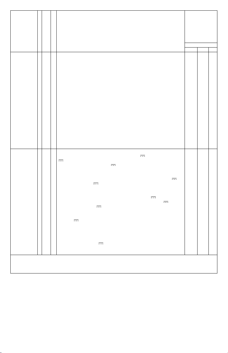
Construction 1
3
4
Mark 1, magnetic coupling
Mark 3, multi-turn
Mark 4, thru-shaft
Available
Options “A”
signies
available with
corresponding
construction
style
Mark
),
), 1/4 hp
1 3 4
A
--
A
A
A
A
A
A
A
A
A
A
A
A
A
A
A
A
A
A
A
A
A
A
A
A
A
--
A
--
A
--
A
A
A
--
A
--
A
--
A
A
A
--
A
--
A
A
A
A
A
--
A
--
A
A
A
A
A
A
A
A
A
A
A
A
A
A
A
A
A
A
A
A
A
A
A
A
A
A
A
A
A
A
A
A
A
A
A
A
Output Type 1
Switch Type
and Rating
*Mark 1 and 4 potentiometer and transmitter outputs will have no switches when ordered with switch type O; 2
1 switch
2
2 switches
3
1 kΩ potentiometer 1/2%; Available with switches, see note below*
31
1 kΩ potentiometer 1/4%; Available with switches, see note below*
32
2 kΩ potentiometer; Available with switches, see note below*
35
5 kΩ potentiometer; Available with switches, see note below*
310
10 kΩ potentiometer; Available with switches, see note below*
320
20 kΩ potentiometer; Available with switches, see note below*
4
4 switches
5
Transmitter 1 kΩ potentiometer 1/2%; 4-20 mA; Available with
switches, see note below*
51
Transmitter 1 kΩ potentiometer 1/4%; Available with switches, see note
below*
52
Transmitter 2 kΩ potentiometer; Available with switches, see note
below*
6
6 switches; Available with switch types B, C, I, R, V, W (UL and CSA
approved units only)
7
AS-interface and 1 switch; Available with switch types B, I, R, W
8
AS-interface and 2 switches; Available with switch types B, I, R, W
9
Transmitter with HART
note below*
A
SPDT snap, rated: 15 A @ 125/250/480 VAC (~); 1/8 hp @ 125 VAC
(~), 1/4 hp @ 250 VAC (~), 1/2 A @ 125 VDC (
)
(
Inductive sensor. 10-30 VDC (
B
SPDT high temperature snap, 350°F (176°C) for 600 hours, rated:
C
15.1 A @ 125/250/277 VAC (~)
DPDT snap, rated: 10 A @ 125/250 VAC (~), 0.3 A @ 125 VDC (
D
0.15 A @ 250 VDC (
SPDT gold contact snap, rated: 1 A @ 125 VAC (~)
G
SPDT hermetically sealed snap, rated: 1 A @ 125 VAC (~)
H
NAMUR inductive sensor; 15 mA max @ 5-25 VDC (
I
SPDT magnetic blow-out, rated: 10 A @ 125 VAC (~)/VDC (
M
@ 125 VAC (~)/VDC (
No switches
O
SPDT hermetically sealed reed, rated: 2 A @ 125 VAC (~), 2 A @
R
24 VDC (
SPDT snap, rated: 4 A @ 125/250 VAC (~)
S
SPDT high temperature snap, 250°F (121°C) continuous, rated: 5 A @
T
125/250/480 VAC (~)
SPDT snap, rated: 10 A @ 125/250 VAC (~), 1/3 hp @ 125/250 VAC
V
(~), 1/2 A @ 125 VDC (
(tungsten)
SPDT gold contact snap, rated 0.1 A @ 125 VAC (~)
W
)
®
communication; Available with switches, see
), 1/4 A @ 250 VDC
); Load: 0.1 A
)
)
), 1/4 A @ 250 VDC (), 4 A @ 125 VAC (~)
)
switches if ordered with switch types B, C, D, I, R, V, or W; and 4 switches if ordered with switch type S. Mark 3
potentiometer and transmitter outputs will have no switches when ordered with switch type O, and 2 switches if
ordered with switch types A, G, M or T.
4
Page 5
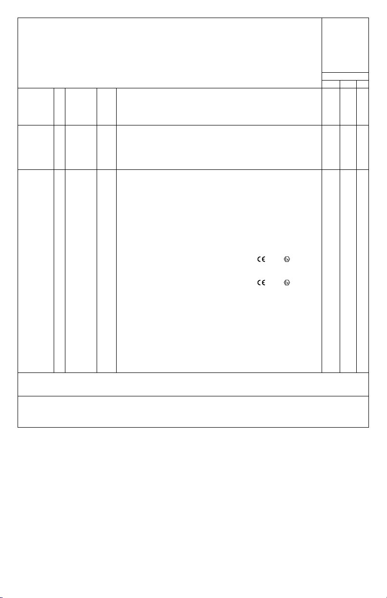
Available
Options “A”
signies
available with
corresponding
construction
style
Mark
1 3 4
Driving
MethodAD
Enclosure 0
Options C1
*Utilizes Asco Valve, Inc. Solenoid Operator Cat. Nos. HV298934001 and HV298934002. Solenoid Operator
Certicate of Conformity numbers: IECEx UL 10.0040X Issue No. 5, ATEX Certicate number DEMKO 10 ATEX
1007782X Rev. 3. Operating Fluid Temperature Range of -20°C to +49°C.
Example: 12VD0-J1. Mark 1, 2 switches both type V – SPDT, direct drive, painted aluminum enclosure with junction
package.
Example: 15VD0. Mark 1, 2 switches both type V – SPDT, 4-20 mA transmitter, direct drive, painted aluminum
enclosure.
E
L
M
1
2
5
6
7 thru 20
A direct or yoke drive without visual indicator
Direct drive (or yoke) with visual indicator
Direct or yoke drive with visual indicator, single window
Lever drive (shaft projection) without visual indicator
Lever (shaft projection) with visual indicator
Aluminum, painted black
Aluminum, painted white epoxy with SS trim
Aluminum, painted red
Aluminum, painted (color not yet specied)
Cast 316 SS
Aluminum, painted (color not yet specied)
Long dwell cam (not on Mark 3)
C2
Double cam (not on Mark 3)
FKM
FKM seals
J1
Junction package with one 1/2˝ NPT female conduit connection
and terminal strip
J2
Junction package with two 1/2˝ NPT female conduit
Connection and terminal strip
SV1
1 attached solenoid valve (must be ordered with J1 option)*
SV2
2 attached solenoid valves (must be ordered with J2 option)*
MT
Metric threaded conduit connection, M25 X 1.5 (M20 X 1.5 for
optional J1 and J2 connections)
B
Directive 2014/34/EU, KEMA 03ATEX2391 X,
db IIC T6 Gb -25/-40/-50°C ≤ Tamb ≤ 63°C depending on output
switch type selected
IS
Directive 2014/34/EU, KEMA 03ATEX1392 X,
ia IIC T4 Ga
IE
IECEx DEK 11.0056X Ex db IIC T6 Gb -25/-40/-50°C ≤ Tamb ≤
63°C depending on output and switch type selected
II
IECEx DEK 11.0061X Ex ia IIC T4 Ga
PP
Plug J1, J2 ports (ATEX and IECEx units supplied with appropriate
Ex db certied plug(s) which maintain IP rating.)
SS
SS Plug J1, J2 Ports (ATEX and IECEx units supplied with
appropriate Ex db certied plug(s) which maintain IP rating)
PT
Paper tag
STR
SS tag riveted
STW
SS tag wired
2813 II 2G Ex
2813 II 1G Ex
A
A
A
A
A
A
A
A
A
A
A
A
A
A
A
A
A
A
A
A
A
A
A
A
A
A
A
A
A
A
A
A
A
A
A
A
A
A
A
A
A
A
A
A
A
A
A
A
A
A
--
A
--
A
A
A
A
A
A
A
--
A
--
A
A
A
A
A
A
A
A
A
--
A
A
A
A
A
A
A
A
A
A
A
5
Page 6
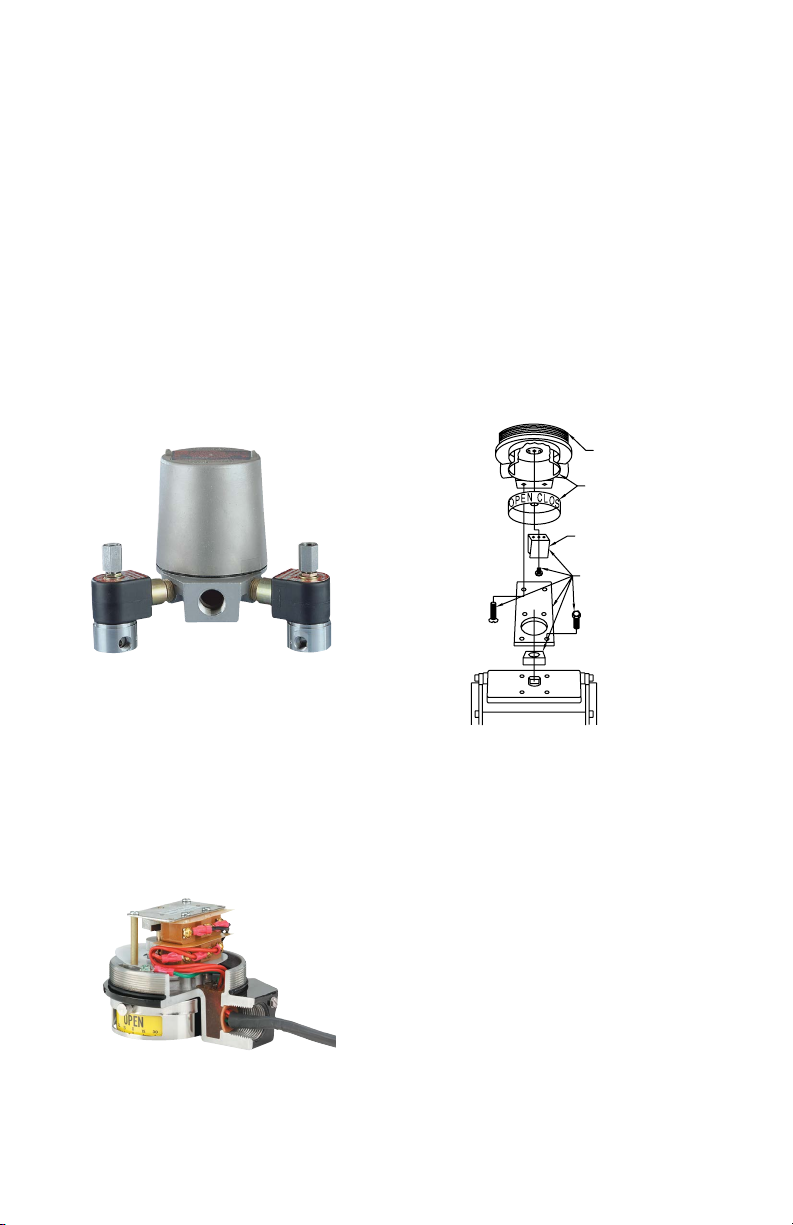
JUNCTION PACKAGE
R
Complete factory assembled packages combine visual
indication, solenoids, switches and transmitter in a single
convenient UL, CSA, IECEx certied or ATEX compliant
assembly which saves labor and reduces cost. The
simple package is shipped ready for installation, complete
with optional custom designed mounting kit for your
specic application. Many options are available such as
painted aluminum, epoxy coated aluminum or stainless
steel housings including a standard 3/4˝ NPT conduit
entrance and choice of 1 or 2 additional 1/2˝ NPT conduit
entrances. The optional conduit entrances are drilled and
tapped in the base of the position indicator housing and
solenoid valves are screwed into the entrances. 22 to 16
AWG wire leads from solenoids, switches and optional
transmitter are terminated in prelabeled, easy-access
terminal strips protected inside the housing. Note:
UL and CSA approval and ATEX compliance requires
complete package assembly by Proximity. Consult the
factory for recommended UL and CSA approved or ATEX
or IECEx compliant solenoid valve options. ATEX and
IECEx solenoid valve options are approved for II 2 G Ex
d IIB T6 Gb -20°C ≤ Tamb ≤ 50°C IP 66. Please consult
page 2 and 3 for ATEX Safety Code.
MOUNTING KITS
Mounting kits are available for direct installation of the
Proximity Controls Mark Series onto most valve and
actuator brands. Proximity Controls has over 2000 kits
available and can custom make kits for any application.
Each kit is specially designed for a particular actuator or
valve, making eld mounting simple with standard tools.
Mounting kits can be used with any model in the Mark
Series, since external features are identical. Rotary valve
kits utilize direct drive couplings, while linear valve kits
use a lever drive.
Kits include a drive yoke or slotted lever arm, bracket,
and fasteners made in either zinc plated steel or stainless
steel. The high strength, spring tempered, stainless
steel drive yoke/coupling is tailored to t securely to a
specic valve or actuator stem ensuring that there is no
slippage or binding. No special alignment xtures are
required due to switch-offset design and yoke to stem
engagement that makes installation a snap.
If you have purchased this unit without a mounting kit,
please contact us to get the proper kit for your application.
Junction
package
Note: Junction package is not available on six switch
models, switch type A, D, G, H, and T models.
FACTORY SEALED LEADS
Eliminate the possibility of conduit contamination and
the need for seal ttings with Proximity’s factory sealed
(potted) leads. This seal has been UL tested to 6000 psi
(413 bar) and is UL and CSA listed for Class I, Groups
A, B, C, D; Class II, Groups E, F and G; Div. 1 and 2
locations. Groups may vary depending on the switch
model. Standard leads are 16 AWG and 36˝ (91.44 cm)
long.
Factory seal
cutaway of
Model 12ADO
SWITCH
VISUAL INDICATO
DRIVE YOKE
MOUNTING KIT
VISUAL INDICATOR
A stainless steel mechanical visual indicator is standard
on direct drive units. The indicator provides visual open
and closed indication and a degree scale, which can
easily be seen from 75 feet away. The scale is adjustable
in 15° increments and the windows are adjustable in a
56° range with 90° xed increments. Factory options
include 180° indication, ow path indication, special
colors, and LED’s.
6
Page 7
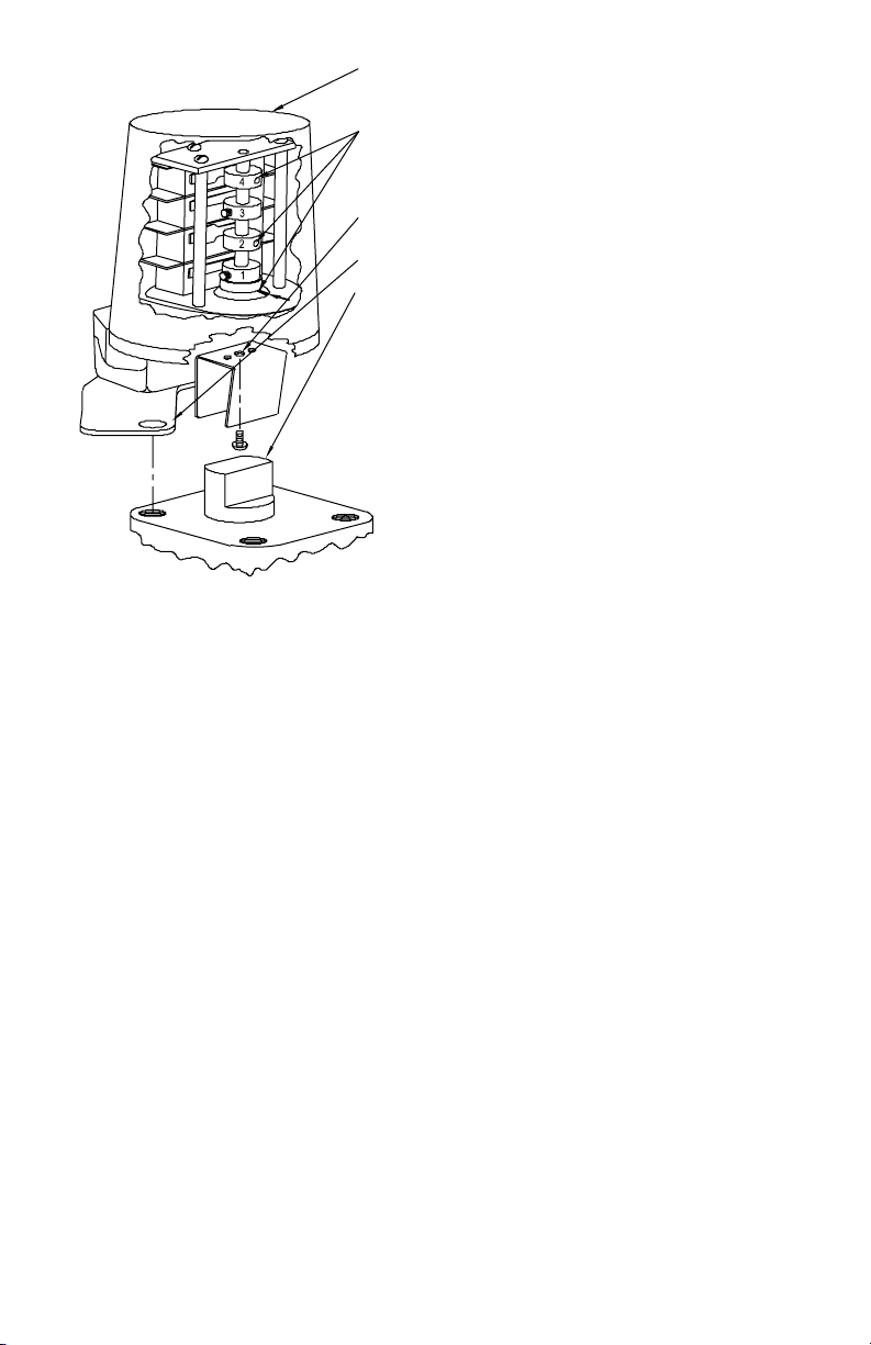
MARK 1 AND 4 DIRECT DRIVE INSTALLATION
1.
3.
4.
5.
2.
Installation Procedure
1. Unscrew cover. Keep threads clean and free from
damage.
2. Switches are set at factory when in counterclockwise
position. Index marks should appear as shown (Mark
1 only). Set screws, or holes in manual cams, (#2, 4
and 6) on Closed switches will be directly above
index marks.
2 Switch Unit #1 Open #2 Closed
4 Switch Unit #1, 3 Open #2, 4 Closed
6 Switch Unit #1, 3, 5 Open #2, 4, 6 Closed
3. Attach appropriate Drive Yoke onto two pins using
a #6-32 screw provided. (Note: Coupling is a special
spring temper yoke or solid metal block. Do not
attempt to fabricate your own yokes.)
4. Attach mounting bracket (127-003 is shown) to
switch housing using 1/4˝ screws provided.
5. With actuator shaft rotated to its counterclockwise
position, spread the drive yoke and slip it down
onto the square (or rectangular) part of the actuator
shaft. Attach bracket with two hex cap screws. Before
tightening screws, operate control slowly with
a wrench or power, and observe that drive shaft
and drive yoke are concentric and perpendicular
in complete stroke. Adjust position as required, and
tighten all the mounting screws. Check concentricity
and perpendicularity. Readjust per above steps as
necessary.
Adjustment Procedure
A. Using a wrench or power, rotate the actuator shaft to
extreme clockwise position. All switches should
change to their opposite function.
B. The cam can be relocated and repositioned by
loosening the set screw. To adjust manual cams,
grasp cam on knurled segment of cam surface.
Simply rotate the cam on spline attached to the
shaft. Feeling or sound of clicks indicates 6º
incremental adjustments. Stop rotating and release
pressure on cam when it is at proper actuation point.
This allows cam to engage spline. Check the circuit
to verify contact at proper point. Rotate shaft. Repeat
steps above as necessary. Lock manual cam on
spline by tightening set screw provided for additional
security.
C. Screw on cover and tighten against O-ring seal until
cover does not turn.
See Pages 14-19 for wiring procedure, intrinsic safety
parameters, relevant warnings and schematics.
7
Page 8
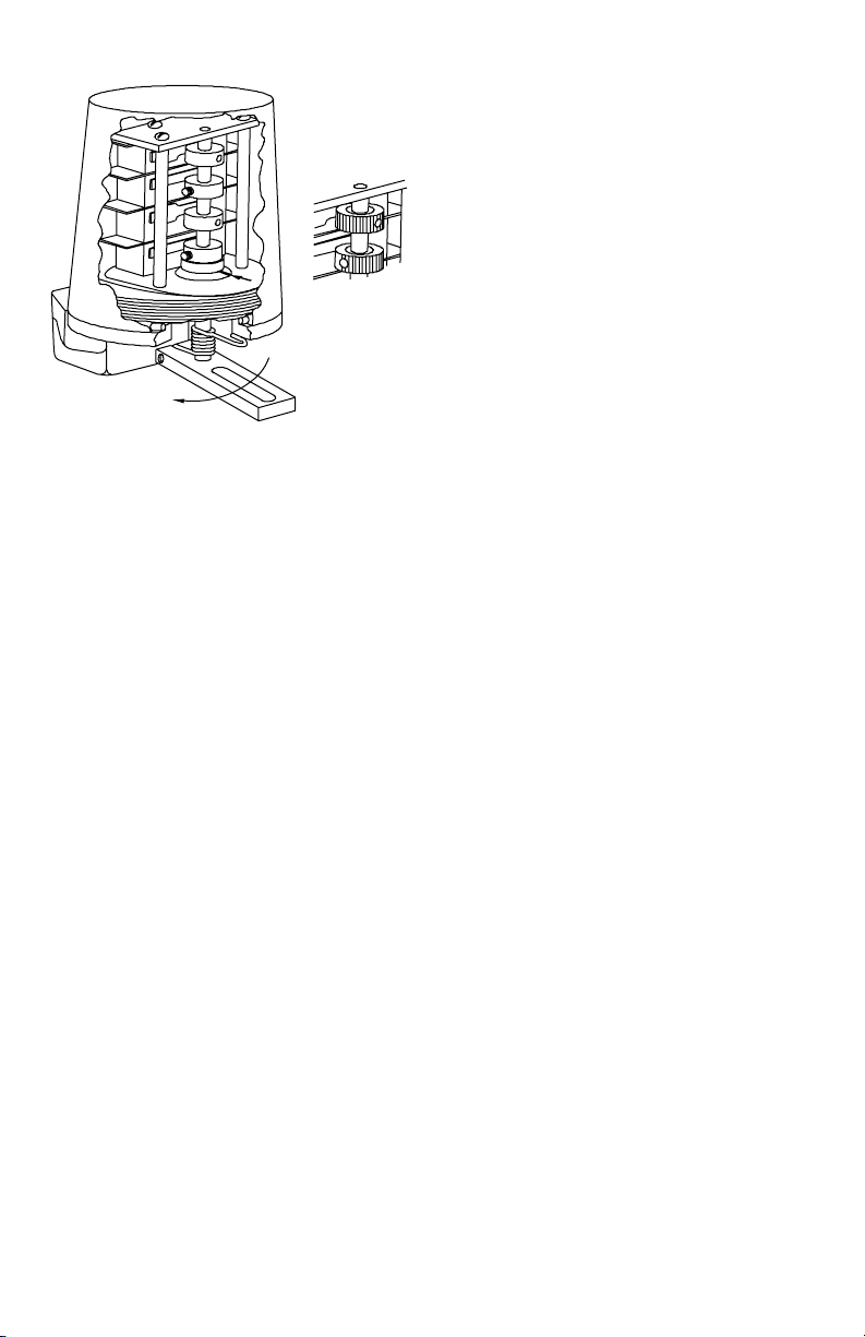
MARK 1 AND 4 LEVER DRIVE INSTALLATION
CLOCKWISE
4
3
2
1
Installation Procedure
1. Attach proper mounting bracket to switch housing
using screws provided. Tubular spacers are provided
for some installations.
2. Attach appropriate driving lever onto shaft. Do not
tighten.
3. Attach switch and bracket to actuator, making sure
that lever is free to rotate over entire range of actuator
stroke.
4. Attach driving pin or bolt through lever arm if slotted,
or on driving side of solid lever. (It may be necessary
to loosen or remove mounting bracket to accomplish
connection on some actuators.)
5. Operate actuator very slowly and observe movement
of all pins and levers to be sure there are no
interferences. Slide lever up or down on switch
shaft to most desirable position. When all motions
are made and clearances are adequate, tighten
clamp screw on lever that was left loose in step 2.
Tighten all mounting screws. Recheck the travel of all
levers and pins for proper clearance through the
entire stroke of the actuator.
6. Unscrew cover. Keep threads clean and free from
damage. Index marks are imprinted into driven
magnet collar as shown (Mark 1 only). Set screws or
holes in manual cams (#2, 4 and 6) will be directly
above index marks on those switches that are
Closed. Marks must be in line when making switch
cam adjustments. Cams are set at factory when in
the counterclockwise position, as shown, and listed
as follows:
2 Switch Unit #1 Open #2 Closed
4 Switch Unit #1, 3 Open #2, 4 Closed
6 Switch Unit #1, 3, 5 Open #2, 4, 6 Closed
90º travel in clockwise direction will reverse all of
above switch positions.
4
3
Adjustment Procedure
A. Operate actuator to full closed position. Set screws
hold cams in place on the shaft. For manual cams,
grasp cam on knurled segment of cam surface and
simply rotate cam to get correct actuation point. Clicks
indicate incremental adjustments. Applying pressure
on cam in direction of protruding actuation segment
of cam surface, and rotating, eliminates incremental
adjustments. Stop rotating and release pressure
on cam when at proper actuation point. This allows
engagement of cam to spline. Check circuit to verify
contact at proper point. Repeat the cam adjustment
steps as necessary. Lock manual cam on spline with
set screw provided for additional security.
B. Operate actuator to opposite extreme (full open),
and adjust cams to suit.
C. Screw on cover and tighten against O-ring seal until
cover does not turn.
See Pages 14-19 for wiring procedure, intrinsic safety
parameters, relevant warnings and schematics.
8
Page 9
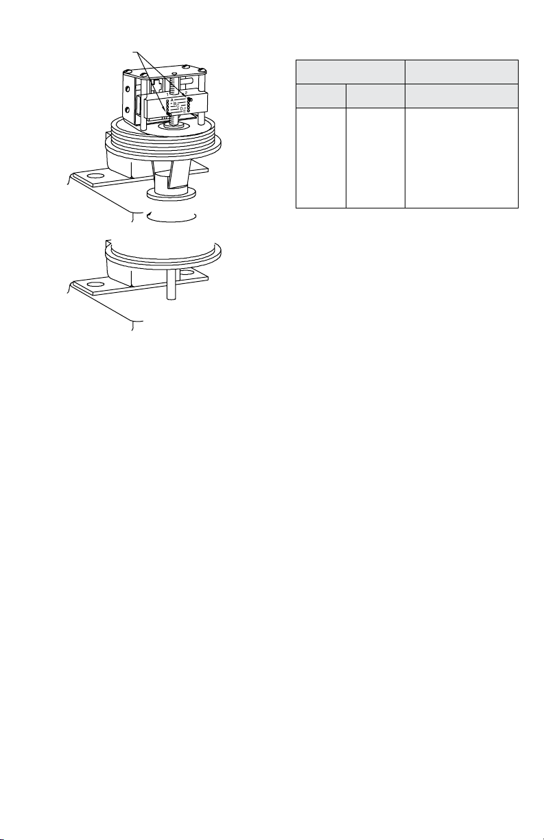
MARK 3 DIRECT AND LEVER DRIVE INSTALLATION
CAM SCREWS
YOKE DRIVE
CLOCKWISE
SHAFT DRIVE
Installation Procedure
Mount the switch as necessary, concentric and
perpendicular over the rotating shaft that is to be
monitored. Direct drive yokes are available in many
widths and lengths to t your needs (Yokes are fabricated
from spring temper stainless steel. Do not attempt to
fabricate your own yokes.) Shaft drive units require an
appropriate coupling (exible type recommended) to the
shaft being monitored.
Adjusting Procedure
1. Remove cover by unscrewing. Take care to keep
threads clean and free from damage.
2. Clockwise rotation of the yoke or shaft will move the
bar up, counterclockwise moves it down.Switches are
set at the factory for approximately one revolution of
the yoke or shaft to actuate switch #1. Notice, that the
cam screw for switch #1 is in location E. By changing
that cam screw to location D, three additional
revolutions of the yoke or shaft will be required to
actuate #1 switch. Moving the cam screw to holes C,
B or A will add three revolutions for each location
moved, until 13 revolutions are required between
switch #1 and 2 actuation.
3. The cam screw for switch #2 in location A. By moving
it to location B, C, D, or E, three revolutions are
added for each location change.
4. Rotate the switch slowly through the full cycle several
times before tightening the bolts securely. Observe
the rotation for signs of yoke or shaft misalignment
or binding with the actuator shaft. Correct as
necessary, then tighten the mounting bolts and
recheck alignment.
5. The following chart shows the various combinations
of screw positions and resulting revolutions between
switch actuation.
Cam Screw Locations
Switch #1 Switch #2
E
D
C
B
A
A
A
A
A
6. Switch actuation at all intermediate number of
revolutions or partial revolutions can be selected by
turning the cam screws in or out when located at the
nearest location shown above. Any partial number of
turns may be selected, such as 4-1/2 or 12-3/4.
See Pages 14-19 for wiring procedure, intrinsic safety
parameters, relevant warnings and schematics.
A
D
A
A
A
B
C
D
E
Number of
Revolutions
Between Switch
Actuation
1
4
7
10
13
16
19
22
25
9
Page 10
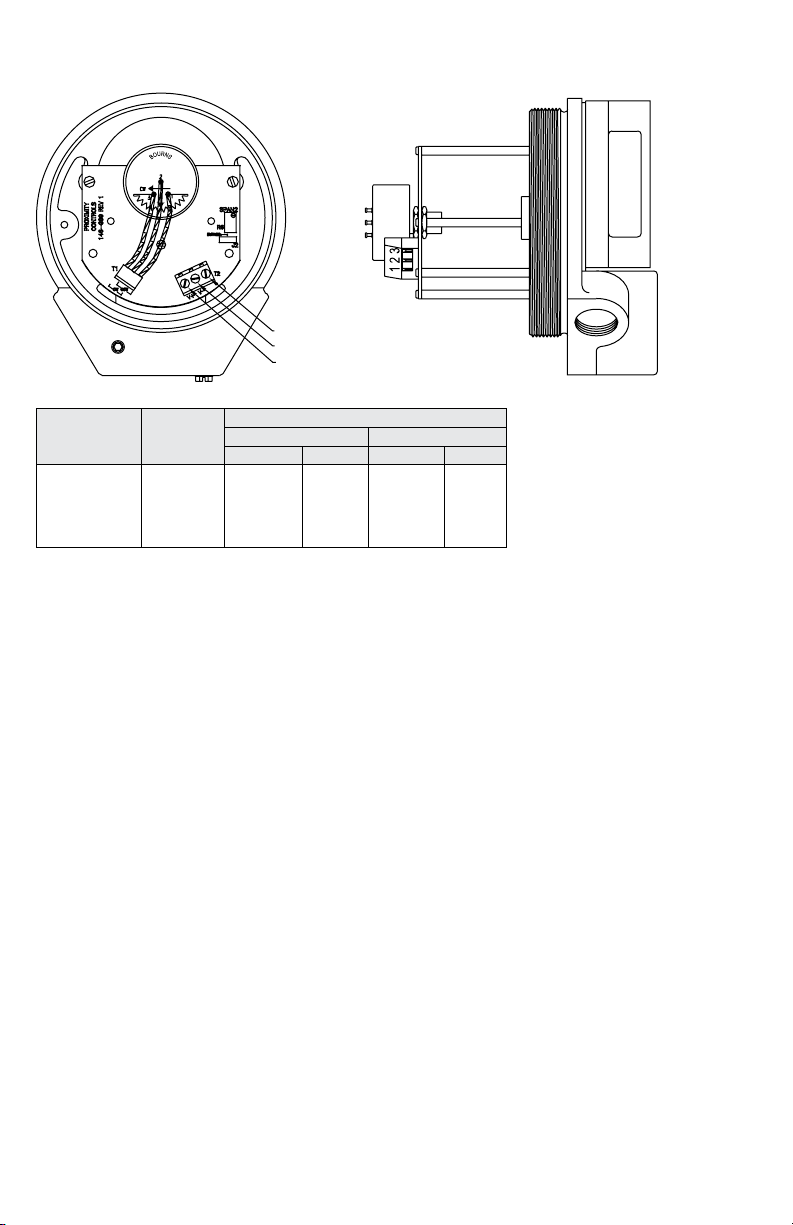
MARK 1, 3 AND 4 WITH POTENTIOMETER INSTALLATION
TERMINAL 3
TERMINAL 2
TERMINAL 1
Potentiometer
Resistance Ω
1000
2000
5000
10000
20000
Installation and Adjustment
1. Attach the switch to the actuator or valve. Refer to
Installation and Adjustment Instructions:
p. 7 for Direct Drive Mark 1 and 4 Models
p. 8 for Lever Drive Mark 1 and 4 Models
p. 9 for Mark 3 Models
2. Remove cover by unscrewing. Take care to keep
threads clean and free from damage.
3. On models 13XXX and 43XXX, the switches are set
at the factory when in the counterclockwise position
as shown. Switch #1 is open, and #2 is closed.
When cams are rotated 90º clockwise, #1 becomes
closed and #2 is open. The cams may be adjusted to
increase or decrease the 90° rotation. For model
33XXX refer to pages 9 and 10 for Switch
Adjustment Procedure.
4. The potentiometer is positioned at the factory with
the resistance element approximately centered. The
resistance readings in the chart are typical of each
different potentiometer.
5. To adjust the potentiometer to a different range,
loosen the two lower set screws on the coupling.
While holding the cams in the desired position, rotate
the coupling and potentiometer shaft to the preferred
location. Rotating clockwise reduces resistance
between pins 2 and 1, and increases resistance
between 2 and 3. Rotating counterclockwise
increases resistance between pins 2 and 1, and
reduces resistance between 2 and 3. If the
resistance “jumps” rapidly, the pot is improperly rotated
and functioning in the 20º dead area. Retighten the 2
set screws. A 2 kΩ span adjustment pot is provided,
to activate move bypass shunt to the other pin.
See Pages 14-19 for wiring procedure, intrinsic safety
parameters, relevant warnings and schematics.
Ω Per
Degree
of Rotation
2.9
5.8
14.7
29.4
58.8
Resistance Between Pins
No. 2 to No. 1 No. 2 to No. 3
CCW-SET CW-90° CCW-SET CW-90°
500
1000
2500
5000
10000
235
471
1178
2354
4708
500
1000
2500
5000
10000
765
1529
3823
7646
15294
10
Page 11
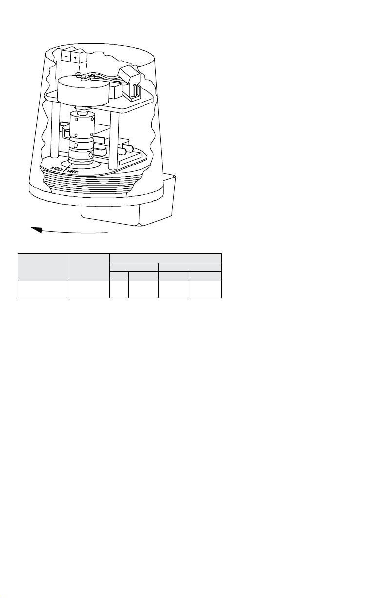
ROTATION
MARK 1, 3 AND 4 WITH TRANSMITTER INSTALLATION
1
2
3
2
1
CLOCKWISE
Potentiometer
Resistance Ω
1000
2000
Models 15XXX, 35XXX and 45XXX Rotary Position
Indicating Switches contain a 4-20 mA transmitter and
two Single Pole Double Throw (SPDT) switches. Models
150XX, 350XX and 450XX contain a 4-20 mA transmitter
only, no switches.
• 4-20 mA output is fully adjustable for various rotations
(zero and span). See chart above for rotation ranges
using various potentiometers.
• 4-20 mA circuit is supply reversal protected and
thermal protected.
• Clockwise or counterclockwise rotation corresponding
to increased current output can conveniently eld
selected with plug connector.
Installation and Adjustment
1. Attach the switch to the actuator or valve. Refer to
Installation and Adjustment instructions:
p. 7 for Direct Drive Mark 1 and 4 Models
p. 8 for Lever Drive Mark 1 and 4 Models
p. 9 for Mark 3 Models
2. Remove cover by unscrewing. Take care to keep
threads clean and free from damage.
3. On models 15XXX and 45XXX, the switches are set
at the factory when in the counterclockwise position
as shown. Switch #1 is open, and #2 is closed. When
cams are rotated 90º clockwise, #1 becomes closed
and #2 is open. The cams may be adjusted to
increase or decrease the 90º rotation. For model
35XXX refer to pages 9 and 10 for Switch
Adjustment Procedure.
4. The potentiometer is positioned at the factory with the
resistance element approximately centered.
Ω Per
Degree
of Rotation
2.9
5.8
Rotation Range
Mark 1 and 4 Mark 3
Min Max Min Max
50°
25°
300°
150°
1.5 turns
.75 turns
8.5 turns
4.3 turns
11
Page 12
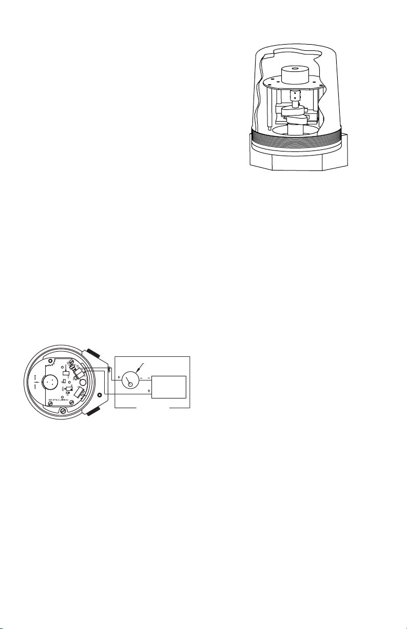
Calibration
A. Set the valve at the position where you want the
meter to read 0% (that is 4 mA). It may be necessary
to move the plug connector to change the direction of
current output to increasing for clockwise rotation or
vice versa.
B. On models 15XXX, loosen the two bottom set screws
on the coupling. Rotate the coupling and
potentiometer shaft to the position where the meter
reads 0% (4 mA). Tighten two set screws.
C. Turn valve to opposite position where meter should
read 100% (20 mA). Use small screwdriver to adjust
the blue rectangular potentiometer “span” until 100%
(20 mA) is on the meter. If it is not possible to reach
100%, refer to Troubleshooting instructions.
D. Return valve to original position at 0% (4 mA). Use
small screwdriver to adjust “zero” turning until 0%
(4 mA) is read on meter. Repeat steps C and D until 4
and 20 mA read consistently on each end of stroke.
Troubleshooting
I. If no current ows, check polarity of current loop (plus
and minus screws on terminal strip). Also check loop
resistance for open line.
II. If full output current cannot be achieved by
adjustment, voltage at transmitter may be too low. If
so, increase power supply voltage until a minimum of
15 V is registered or move voltage shunt to 12 VDC.
III. If current increases and decreases in the wrong
direction, move the plug connector from CW to CCW
or vice versa.
IV. Check specs to make sure you are in range of
adjustment, (See chart on previous page).
V. If the zero adjustment does not have enough range,
the zero must be mechanically realigned as follows:
Set the “zero” (ne 4 mA) adjustment to the middle of
its range. (Full multi-turn range is 25 revolutions; set
at 12-1/2 revolutions.) Repeat calibration steps B, C
and D.
4-20 mA METER
24 VDC
POWER
SUPPLY
OPTIONAL
2-wire connections
See Pages 14-19 for wiring procedure, intrinsic safety
parameters, relevant warnings and schematics.
®
MARK 1 AND 4 TRANSMITTER WITH HART
COMMUNICATION INSTALLATION
2
1
Models 19XXX, 39XXX and 49XXX Rotary Position
Indicating Switches contain a 4-20 mA transmitter with
®
communication and two Single Pole Double
HART
Throw (SPDT) switches. Models 190XX, 390XX and
490XX contain a 4-20 mA transmitter with HART
communication only, no switches.
• 4-20 mA output is fully adjustable for various
rotations (zero and span) using pushbuttons or a
®
HART
• 4-20 mA circuit is polarity insensitive and thermal
communication master.
protected. Though the output terminals are labeled
(+) and (-) the transmitter will function if the terminals
are reversed.
• Clockwise or counterclockwise rotation corresponding
to increased current output can be selected by use of
zero and span pushbuttons or a HART
communication master.
®
Installation and Adjustment
1. Attach the switch to the actuator or valve. Refer to
Installation and Adjustment instructions:
p. 7 for Direct Drive Mark 1 and 4 Models
p. 8 for Lever Drive Mark 1 and 4 Models
2. Remove cover by unscrewing. Take care to keep
threads clean and free from damage.
3. On models 19XXX and 49XXX, the switches are set
at the factory when in the counterclockwise position
as shown. Switch #1 is open, and #2 is closed. When
cams are rotated 90º clockwise, #1 becomes closed
and #2 is open. The cams may be adjusted to
increase or decrease the 90º rotation. For model
39XXX refer to pages 9 and 10 for Switch
Adjustment Procedure.
4. The potentiometer is positioned at the factory with the
resistance element approximately centered.
®
12
Page 13

Circuit Board Features
OPTIONAL OTHERWISE
WP SHUNT
SQUA
LED
Y
• Two test points are provided as a convenience for
attaching HART
• The WP (write project) shunt enables and disables
®
communication master.
the ability to change conguration settings. It can
prevent unintended conguration changes from an
accidental press of the ZERO or SPAN button and
from communications with a HART
master. Set this shunt to ON to prevent conguration
®
communication
changes. Set this shunt to OFF to allow conguration
changes.
• The FAULT shunt determines whether the transmitter
fails high or low in a fault condition. When set to high,
the transmitter will output 21.0 mA in a fault condition.
When set to low, the transmitter will output 3.6 mA in
a fault condition. The transmitter will output 3.8 mA
and 20.5 mA when operating normally.
• The FIND shunt determines if the transmitter will
respond to a FIND command. When set to ON,
the transmitter will respond to HART
master’s Find Command. When set to OFF, the
transmitter will ignore FIND commands. This is useful
for allowing a HART
discover the transmitter
• The LED will ash in response to a HART
communication master’s Squawk Command. This is
useful for identifying a transmitter attached to a HART
communication master.
®
communication master to
®
communication
®
Calibration
A. Place the WP shunt in the OFF position in necessary
to allow calibration to be performed.
B. Set the valve at the position where you want the
meter to read 0% (that is 4 mA). Press and hold the
ZERO pushbutton for two seconds or use a HART
communication master to set the ZERO point
®
C. Turn the valve to opposite position where meter
should read 100% (20 mA). Press and hold the SPAN
pushbutton for two seconds or use a HART
communication master to set the SPAN point.
®
D. Reposition the WP shunt if desired.
WK
FAULT SHUNT
FIND SHUNT
®
HART
COMMUNICATION
MASTER*
4-20 mA METER
+
-
**250Q
TEST POINT
*OPTIONAL, MAYBE CONNECTED TO TEST POINT
AS SHOWN OR TO SCREW TERMINALS
**REQUIRED FOR HART® COMMUNICATIONS,
See Pages 14-19 for wiring procedure, intrinsic safety
parameters, relevant warnings and schematics.
®
-
24 VDC
POWER
+
SUPPL
13
Page 14

WIRING PROCEDURE: GENERAL
ASHER
• Complete all electrical wiring in accordance with local
and national electrical codes by qualied personnel
• It may be necessary to segregate power and signal
circuits in separate conduit entries.
• For units supplied with both internal ground and
external bonding terminals, the ground screw inside
the housing must be used to ground the control. The
external bonding screw is for supplementary bonding
when allowed or required by local code. When external
bonding conductor is required, conductor must be
wrapped a minimum of 180° about the external bonding
screw. See below.
• Products with ying leads shall be terminated in an
approved junction box.
CONDUCTOR
SCREW
LOCKW
CLAMP
WIRING PROCEDURE: HAZARDOUS LOCATIONS,
FLAMEPROOF CABLE CONNECTION:
• The cable entry device shall be Ex certied ameproof
suitable for the conditions of use and installed per
manufacturer’s instructions.
• For ambient temperatures above 58°C, cables and
cable glands suitable for at least 95°C shall be used.
CONDUIT CONNECTION:
• An Ex, UL, or CSA (with appropriate classes and
groups) certied ameproof sealing device such as a
conduit seal with setting compound shall be provided
immediately following the conduit entrance to the
enclosure. UL and CSA listed factory sealed leads are
provided from the factory on request.
• For ambient temperatures above 58°C, the wiring and
setting compound in the conduit seal shall be suitable
for at least 95°C.
• Degree of protection IP66/68W is maintained when
suitable glands/plugs are used for all options.
WIRING PROCEDURE: HAZARDOUS LOCATIONS,
INTRINSIC SAFETY
• Potentiometer, Transmitter and each Switch and/or
NAMUR Sensor must be treated as separate intrinsically
safe circuits.
ELECTRICAL RATINGS:
• Potentiometer, see page 3.
• Transmitter, see page 3.
• Switches, see model chart on page 4.
INTRINSIC SAFETY INPUT PARAMETERS: (SUFFIX
IS and II)
• Potentiometer, Ui = 30 V; Ii = 50 mA; Pi = 0.65 W.; Li =
0 µH; Ci = 0 nF.
• Transmitter, Ui = 30 V; Ii = 100 mA; Pi = 1.3 W; Li = 0
µH; Ci = 0 nF.
• Switches, Ui = 30 V; Ii = 100 mA; Pi = 1.3 W; Li = 0 µH;
Ci = 0 nF.
• Namur Sensor, Ui = 16 V; Ii = 76 mA; Pi = 242 mW; Li
= 50 µH; Ci = 40 nF.
• Transmitter with HART
100 mA; Pi = 1.3 W; Li = 0 µH; Ci = 4 nF.
®
communication, Ui = 30 V; Ii =
14
Page 15
CAUTION
equipment may be impaired if the equipment is used in
a manner not specied by the manufacturer.
• Risk of electric shock - disconnect supply circuit before
opening. Keep unit tightly closed while circuits are alive.
• Suitable insulation between signal wiring and
hazardous voltage wiring must be provided.
WARNING
• Keep cover tightly closed when in operation.
• De-energize supply circuit before opening.
• To prevent ignition of hazardous locations, replace
cover before energizing the electrical circuits.
• After de-energizing delay 3 minutes before opening.
• Do not open or AS-interface equipped
units when an explosive atmosphere may be present.
WARNING
• Repairs only to be conducted by Dwyer Instruments,
Inc.
• Inspect through shaft/bushing joint, of Mark 4,
periodically for wear, if gap exceeds .0033˝ (.0 84
mm) for a length of 1˝ (25.4 mm) return to Dwyer
Instruments, Inc. for repair or replace unit. The thread of
the cover with 4.000-16UN 2A/B must have a minimum
of 7 threads engaged.
WARNING
• Enclosure must be protected from mechanical friction
and impact with iron/steel to prevent ignition capable
sparks.
NOTICE
compliant. These units are not intended for use in
potentially hazardous atmospheres in the EU. These
units may be CE marked for other Directives of the EU.
GENERAL
• Protection provided by the
HAZARDOUS LOCATIONS,
FLAMEPROOF
MARK 1, 3, and FLAMEPROOF
ENCLOSURE OPTION B and IE
HAZARDOUS LOCATIONS,
INTRINSIC SAFETY
Units without sufx B or IS are
not Directive 2014/34/EU (ATEX)
MISE EN GARDE
assurée par l’équipement peut être réduite si celui-ci
n’est pas utilisé conformément aux spécications du
fabricant.
• Risque d’électrocution - débrancher le circuit
d’alimentation avant d’ouvrir. Laisser l’unité bien fermée
lorsque les circuits sont sous tension.
• Une isolation appropriée entre le câblage de
signalisation et le câblage de tension dangereuse doit
être prévue.
AVERTISSEMENT
• Laisser le couvercle bien fermé lorsque l’unité est en
service.
• Couper le circuit d’alimentation avant d’ouvrir.
• An d’empêcher toute ignition dans des zones
dangereuses, replacer le couvercle avant de mettre les
circuits électriques sous tension.
• Laisser passer 3 minutes avant d’ouvrir lors de la mise
hors tension.
• Ne pas ouvrir le ni une unité avec interface AS en
présence d’une atmosphère potentiellement explosive.
AVERTISSEMENT
MARK 1, 3 y 4, OPCIÓN B y IE
• Les réparations ne doivent être effectuées que par
Dwyer Instruments, inc.
• Inspecter périodiquement l’axe/joint de garniture
du Mark 4 an de détecter tout signe d’usure ; si le
jeu excède 0,084 mm (0,0033 po) de largeur pour
une longueur de 25,4 mm (1 po), renvoyer à Dwyer
Instruments, inc. pour faire réparer ou remplacer l’unité.
Un minimum de 7 lets du couvercle doivent être
engagés, avec 4.000-16UN 2A/B.
AVERTISSEMENT
• L’enceinte doit être protégée de la friction mécanique
et de tout impact avec du fer/acier an de prévenir la
création d’étincelles pouvant s’enammer.
GÉNÉRAL
• La protection normalement
ZONES DANGEREUSES,
IGNIFUGE
OPCIÓN DE GABINETE
A PRUEBA DE LLAMAS
ZONES DANGEREUSES,
SÉCURITÉ INTRINSÈQUE
AVIS
de la Directive 2014/34/EU (ATEX). Ces unités ne
sont pas conçues pour une utilisation en atmosphère
potentiellement dangereuses au sein de l’Union
Européenne. Ces unités peuvent être estampillées CE
pour d’autres Directives de l’Union Européenne.
15
Les unités sans sufxe B ou IS ne
sont pas conformes aux exigences
Page 16
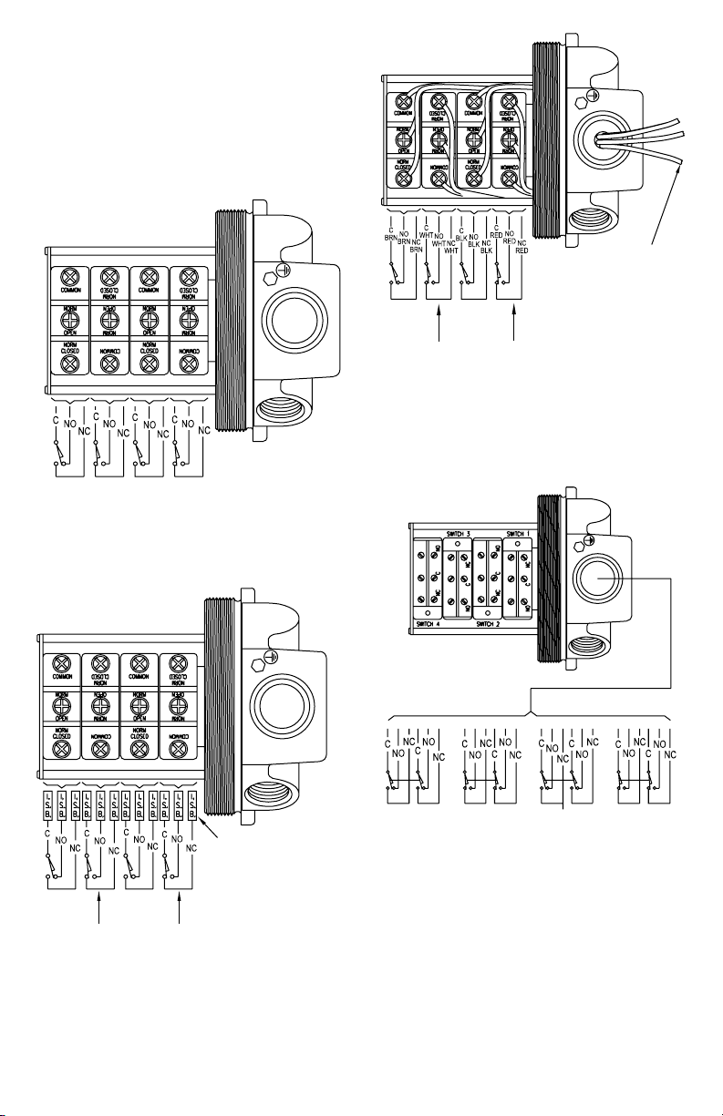
SCHEMATICS: GENERAL AND INTRINSIC SAFETY
SWITCH
SWITCH
SWITCH
SWITCH
SWITCH
SWITCH
SWITCH
SWITCH
SWITCH
A
SWITCH
SWITCH
1. Units supplied with switch option A, G, H, M or T
have screw terminals on the back side of the switch
for terminating wires.
2. UL and CSA units supplied with switch option D are
supplied with 36” minimum (0.91 meters) ying leads.
3. Units supplied with switch option B, C, I, R, S, V or
W are supplied with terminal strips or 36˝ minimum
(.091 meters) ying leads.
4. Units with J1 or J2 sufx are supplied with additional
2 or 4 termination points.
GREEN WIRE
- GROUND
SW 3
ABOVE
ABOVE
2ND
1, 2, or 4 switches
SW 2
ABOVE 1ST
SWITCH
SW 2
1ST
BOTTOM
SWITCH
SW 1
BOTTOM
INTRINSICALLY
SAFE BARRIERS
SW 4
TOP
Figure 1: Wiring for switch types A, G, H, M, and T.
SW 4
TOP
SWITCH
SW 3
ABOVE 2ND
SW 1
SW 4
BOVE 3RD
SWITCH
Figure 3: Wiring for factory sealed leads option. 1,
2, or 4 switches. Switch 1 wires are red, switch 2
wires are black, switch 3 wires are white, and switch
4 wires are brown. Wires are labeled C, NO, NC
SWITCH 4
TOP
Figure 4: Wiring for switch type D. 1, 2, or 4
ABOVE 1ST
SW 3
ABOVE 2ND
SW 2
SWITCH
BOTTOM
SWITCH 3
ABOVE 2ND
SW 1
SWITCH 2
ABOVE 1ST
switches
SWITCH 1
BOTTOM
Figure 2: Intrinsically safe wiring for switch types A,
G, H, M and T. 1, 2, or 4 switches
16
Page 17
ABOVE 2ND SWITCH
BOTTOM SWITCH
INTRINSICALLY
SAFE BARRIERS
OM
SWITCH
SAFE BARRIERS
INTRINSICALLY
SWITCH 4
TOP SWITCH
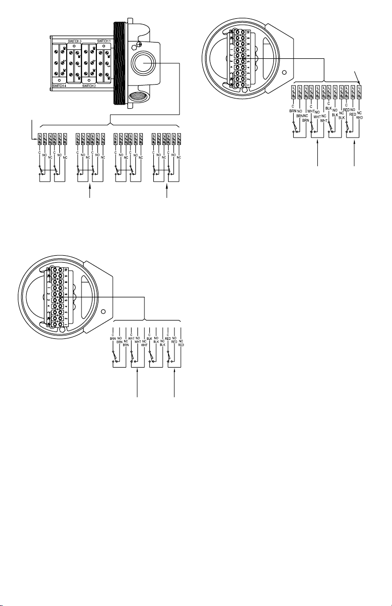
Figure 5: Intrinsically safe wiring for switch type D.
SWITCH 3
1, 2, or 4 switches
SWITCH 2
ABOVE 1ST SWITCH
SW 4
TOP
SWITCH
ABOVE 1ST
SWITCH
SW 3
ABOVE 2ND
SWITCH
SWITCH 1
SW 2
BOTT
SW 1
ABOVE 1ST
SWITCH
SW 3
ABOVE 2ND
SWITCH
SW 2
SW 1
BOTTOM
SWITCH
SW 4
TOP
SWITCH
Figure 7: Intrinsically safe wiring for switch types C,
R, V, and W. 1, 2, or 4 switches
Figure 6: Wiring for switch types C, R, V and W. 1, 2,
or 4 switches
17
Page 18
POTENTIOMETER
TRANSMITTER
SWITCH
SWITCH
A
SWITCH
SWITCH
SWITCH
USE CONNECTOR SUPPLIED
WITH SWITCH ONLY. MAKE SURE
CONNECTOR IS PUSHED ON ALL
THE WAY TO ASSURE A
TIGHT CONNECTION.
SW 6
BOVE 5TH
SWITCH
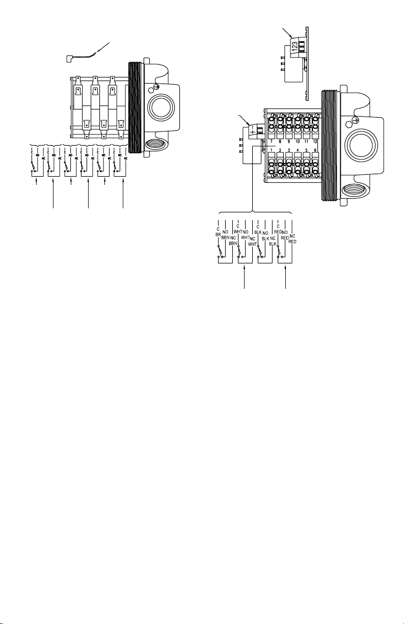
Figure 8: Wiring for switch types B, C, I, R, V, and W.
1, 2, 4, or 6 switches. Switch types B and I have “+”
ABOVE 3RD
SWITCH
SW 5
ABOVE 4TH
SW 4
SW 2
ABOVE 1ST
SWITCH
SW 3
ABOVE 2ND
and “-” terminals
SW 1
BOTTOM
SW 4
TOP
SWITCH
ABOVE 2ND
Figure 9: Wiring for potentiometer and transmitter
outputs with switches. Refer to note at bottom of
SW 2
ABOVE 1ST
SWITCH
SW 3
SW 1
BOTTOM
page 3 for switch details
18
Page 19
TERMINAL 3 SEE WIRING SCHEMATIC
TERMINAL 2 SEE WIRING SCHEMATIC
WIRING SCHEMATIC
TERMINAL 2
SWITCH
SWITCH
TERMINAL 1
SEE WIRING
SCHEMATIC
SPAN ADJUSTMENT
POTENTIOMETER
3
J2
BYPASS
2
1
BY OTHERS
VDC
5
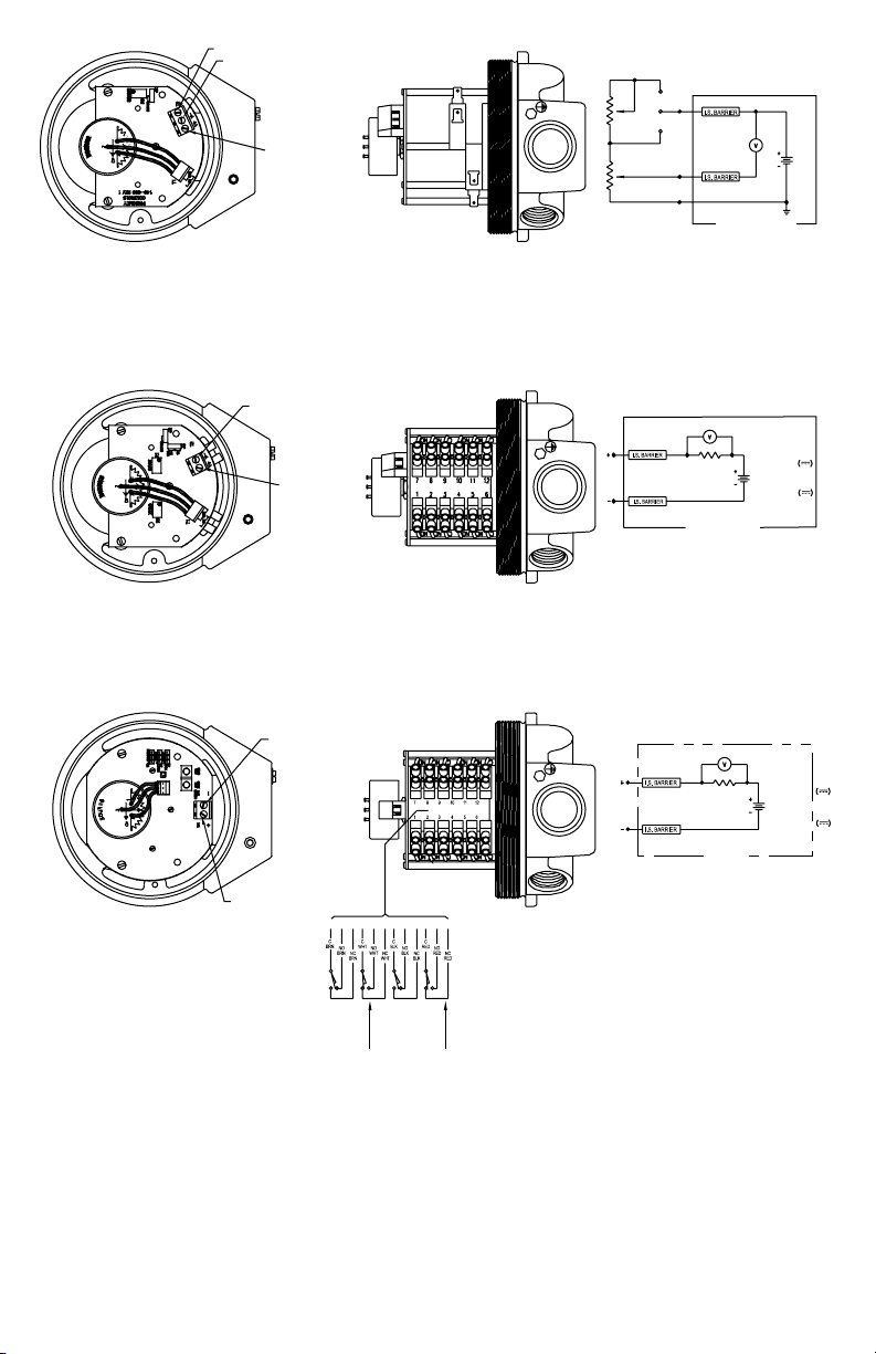
Figure 10: Intrinsically Safe wiring for potentiometer output. Refer to proper switch gure if unit has
switches as well
SEE WIRING
SCHEMATIC
TERMINAL 1
SEE WIRING
SCHEMATIC
WIRING SCHEMATIC
12 VDC
24 VDC
OR
BY OTHERS
Figure 11: Intrinsically Safe wiring for transmitter output. Refer to proper switch gure if unit has switches
as well
SEE WIRING
SCHEMATIC
WIRING SCHEMATIC
12 VDC
OR
24 VDC
BY OTHERS
SEE WIRING
SCHEMATIC
TOP
SW 3
ABOVE 2ND
SW 2
ABOVE 1ST
SWITCH
BOTTOM
SW 1
SW 4
SWITCH
Figure 12: Intrinsically Safe wiring for transmitter with HART
gure if unit has switches as well
19
®
communication output. Refer to proper switch
Page 20

MAINTENANCE AND REPAIR
The moving parts of these units need no maintenance
or lubrication. Some parts are replaceable by qualied
personnel, contact the factory for details.
WARNING
IS, II or IM sufxes. Use a damp cloth with soap and
water for cleaning and decontamination. Solvents may
damage O-ring seals. Units in need of repair should be
returned to the following address, freight prepaid. Be
sure to include a brief explanation of the problem and
any relevant application information.
Proximity Controls
Attn: Repair Department
1431 State Highway 210E
Fergus Falls, MN 56537
LIMITED WARRANTY
Limited Warranty: The Seller warrants all Dwyer
instruments and equipment to be free from defects in
workmanship or material under normal use and service
for a period of one year from date of shipment. Liability
under this warranty is limited to repair or replacement
EXW Ex Works Dwyer Instruments, Inc of any parts
which prove to be defective within that time or repayment
of the purchase price at the Seller’s option provided the
instruments have been returned, transportation prepaid,
within one year from date of purchase. All technical
advice, recommendations and services are based on
technical data and information which the Seller believes
to be reliable and are intended for use by persons
having skill and knowledge of the business, at their own
discretion. In no case is Seller liable beyond replacement
of equipment EXW Ex Works Dwyer Instruments, Inc or
the full purchase price. This warranty does not apply if the
maximum ratings label is removed or if the instrument or
equipment is abused, altered, used at ratings above the
maximum specied, or otherwise misused in any way.
Substitution of components may
impair intrinsic safety of models with
THIS EXPRESS LIMITED WARRANTY IS IN LIEU OF
AND EXCLUDES ALL OTHER REPRESENTATIONS
MADE BY ADVERTISEMENTS OR BY AGENTS AND
ALL OTHER WARRANTIES, BOTH EXPRESS AND
IMPLIED. THERE ARE NO IMPLIED WARRANTIES
OF MERCHANTABILITY OR OF FITNESS FOR A
PARTICULAR PURPOSE FOR GOODS COVERED
HEREUNDER.
BUYER’S REMEDIES
The buyer’s exclusive and sole remedy on account
of or in respect to the furnishing of non-conforming or
defective material shall be to secure replacement thereof
as aforesaid. The Seller shall not in any event be liable
for the cost of any labor expended on any such material
or from any special, direct, indirect, consequential or
incidental damages to anyone by reason of the fact that
it shall have been non-conforming or defective.
HART® is a registered trademark of Hart Communication Foundation
©Copyright 2021 Dwyer Instruments, Inc. Printed in U.S.A. 8/21 FR# 443266-00 Rev. 15
20
DWYER INSTRUMENTS, INC.
P.O. BOX 373 • MICHIGAN CITY, INDIANA 46360, U.S.A.
Phone: 219-879-8000
Fax: 219-872-9057
dwyer-inst.com
e-mail: [email protected]
 Loading...