

Page 1
SERIES MARK
E
POSITION INDICATORS/SWITCHES/TRANSMITTERS
VALVES
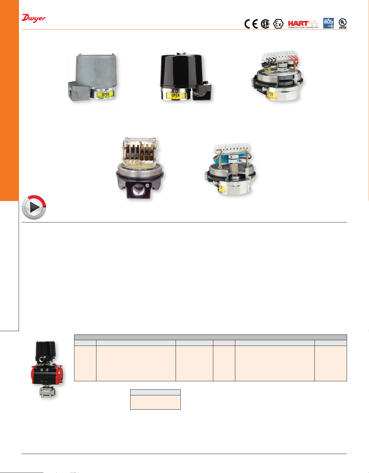
Mark 1
stainless steel
(environmentally sealed
for corrosive areas)
E
O
D
I
V
O
N
L
I
N
The Proximity™ Series Mark Position Indicators/Switches/Transmitters are a line
of position indicators with a selection of various output options. Three model styles
make up the Mark series to cover almost any application. Standard models in the Mark
Series have visual position indicators and are weatherproof, explosion-proof, and
submersible.Alargevarietyofoutputsareavailabletotspecicapplications.There
is a choice of 1 to 6 switch outputs of 14 varieties including inductive sensors, high
temperature switches, gold contact switches, hermetically sealed switches, and high
current switches. Besides the switch outputs the Series offers potentiometer outputs,
transmitters, and HART® Communication. The units are purchased for either direct
drive applications, such as rotary valves, or lever drive applications, such as linear
valves.AdjustablevisualindicatorisstandardondirectdriveunitsthatdisplaysOPEN
/CLOSEDstatusanddegrees.
A magnetic drive that completely seals the switch compartment from the atmosphere
Position Indicators/
for maximum leak protection is utilized in the Mark 1. The Mark 3 uses the same
Switches/Transmitters
magnetic drive of the Mark 1, but it can be used for multi-turn applications with 1 to
25 revolutions, such as gate valves. A through shaft drive is incorporated in the Mark
4 making the unit a more cost effective alternative to the Mark 1 for applications that
are not as demanding.
APPLICATIONS
• Rotary valve actuators and dampers
• Linear valve actuators and cylinders
• Manual valves
• Gear operators
• Positioners
Mark 3
multi turn
polyester coated aluminum
MODEL CHART
Model Function Design Model Function Design
12AD0
12AL0
14AD0
15VD0
12AD1
14AD1
12VD0-J1
14VD0-J1
2 SPDT
2 SPDT (lever drive)
4 SPDT
2 SPDT and 4-20 mA position transmitter
2 SPDT
4 SPDT
2 SPDT
4 SPDT
Mark 1
(environmentally sealed
for corrosive areas)
MARK 1 BENEFITS/FEATURES
• Features a magnetic coupling that isolates the switch compartment, completely
sealing the unit from the surrounding atmosphere for maximum hazard and leak
protection
• EZ set cams on switch models provide simple set point adjustment
• Flexible design allows multiple switches and transmitter options
• Ideal for corrosive environments
MARK 3 BENEFITS/FEATURES
• Features a magnetic coupling that isolates the switch compartment, completely
sealing the unit from the surrounding atmosphere for maximum hazard and leak
protection
• Multi-Turn models that can provide switch signals between 1 and 25 revolutions,
and transmitter models for up to 10 revolutions without gear reduction
• Flexible design allows multiple switches and transmitter options
• Ideal for corrosive environments
MARK 4 BENEFITS/FEATURES
• Thru-Shaftdesignthatfeaturesa1˝bushingforlonglifeandO-ringstosealthe
switch compartment for hazard, corrosion, and leak protection
• EZ set cams on switch models provide simple set point adjustment
• Flexible design allows multiple switches and transmitter options
• A more cost effective alternative to the Mark 1 Series for less demanding
applications
Magnetic coupling
Magnetic coupling
Magnetic coupling
Magnetic coupling
Magnetic coupling
Magnetic coupling
Magnetic coupling
Magnetic coupling
Mark 4
thru-shaft cutaway
Model 42RDOJ2
42AD0
44AD0
45VD0
42VD0-J1
44VD0-J1
2 SPDT
4 SPDT
2 SPDT and 4-20 mA position transmitter
2 SPDT
4 SPDT
magnetic coupling cutaway
Mark 1
Model 12VDOJ2
Thru-shaft drive
Thru-shaft drive
Thru-shaft drive
Thru-shaft drive
Thru-shaft drive
Mark Series
mounted to an actuator
DWYER INSTRUMENTS, LLC | dwyer-inst.com434
Stainless Mounting Kit
1/4 turn actuator
Manual 1/4 turn valves
Linear control valves
Mounting kits with drive yoke (see drawing), or slotted lever arm, bracket, fasteners
andotherstainlesssteelhardwaretover2000popularvalvesandactuators.Ahigh
strengthspringtemperedstainlesssteeldriveyoke/couplingistailoredtotsecurelyto
aspecicvalveoractuatorstem.Thereisnoslippageorbinding.Nospecialalignment
xturesare requireddue toswitchoffsetdesignand yoketo stemengagement that
makes installation a “snap”. Each kit is specially designed for a particular valve or
actuator,makingeldmountingsimplewithstandardtools.Pleasespecify makeand
model of valve or actuator on order.
Mounting kits can be used interchangeably with all models since external mounting
features are identical. Rotary valves utilize direct drive couplings and a slotted lever
drive is used with linear valves. Lever drives convert linear motion to rotary. Stainless
steel visual indicators are standard for direct drive, automated quarter-turn valve
applications.
Page 2
SERIES MARK
POSITION INDICATORS/SWITCHES/TRANSMITTERS
VALVES
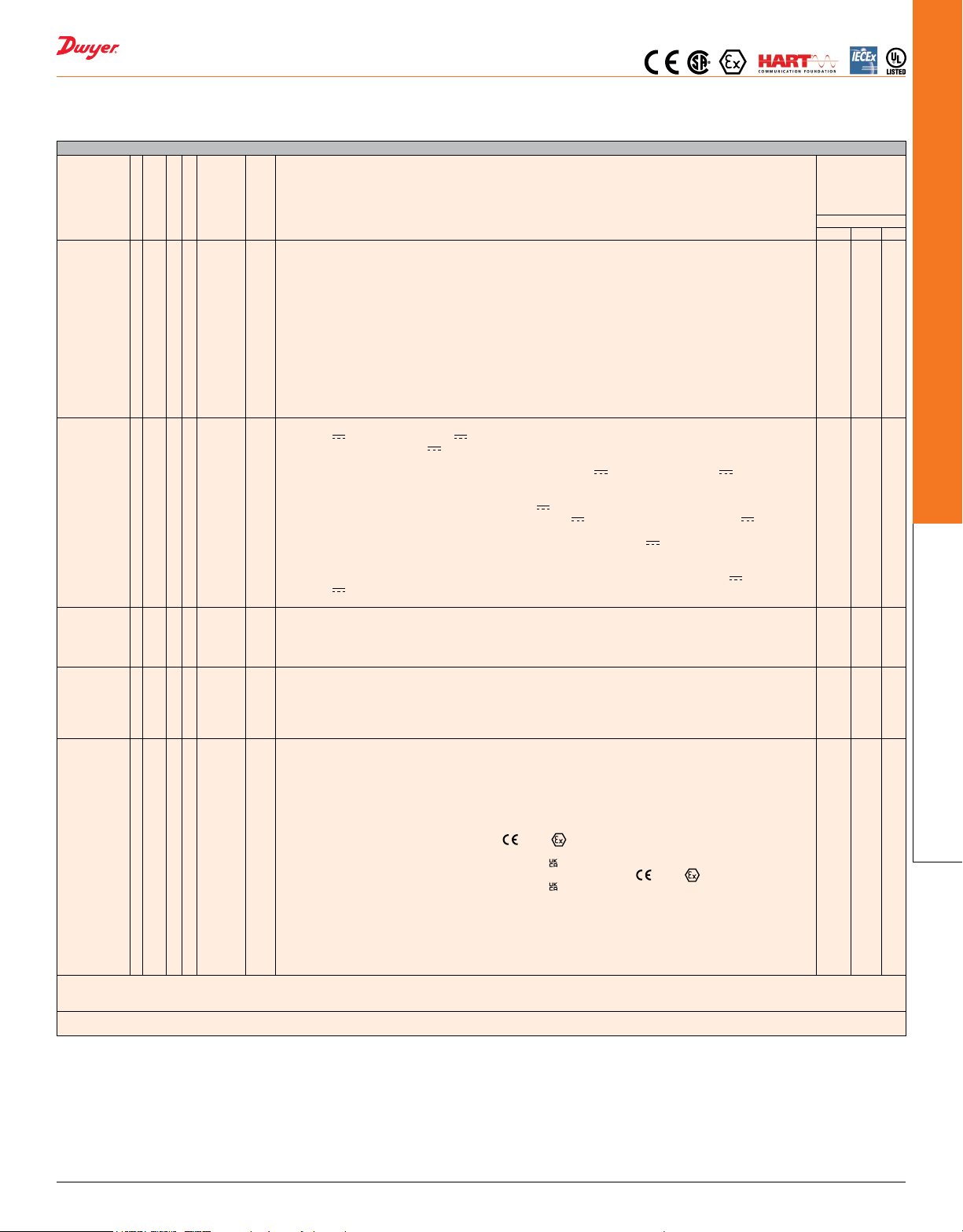
MODEL CHART
Construction 1
Output Type 1
Switch Type
and Rating
Driving
Method
Enclosure 0
Options C1
*Mark 1 and 4 potentiometer and transmitter outputs will have no switches when ordered with switch type O; 2 switches if ordered with switch types B, C, D, I, R, V, or W; and
4 switches if ordered with switch type S. Mark 3 potentiometer and transmitter outputs will have no switches when ordered with switch type O, and 2 switches if ordered with
switch types A, D, G, M or T.
Example: 12VD0-J1. Mark 1, 2 switches both type V – SPDT, direct drive, painted aluminum enclosure with junction package.
Example: 15VD0. Mark 1, 2 switches both type V – SPDT, 4-20 mA transmitter, direct drive, painted aluminum enclosure.
3
4
2
3
31
32
35
310
320
4
5
51
52
7
8
9
A
B
C
D
G
H
I
M
O
R
S
T
V
W
A
D
E
L
M
1
2
5
6
7 thru 20
Mark 1, magnetic coupling
Mark 3, multi-turn
Mark 4, thru-shaft
1 switch
2 switches
1 kΩ potentiometer 1/2%. Available with switches, see note below*
1 kΩ potentiometer 1/4%. Available with switches, see note below*
2 kΩ potentiometer. Available with switches, see note below*
5 kΩ potentiometer. Available with switches, see note below*
10 kΩ potentiometer. Available with switches, see note below*
20 kΩ potentiometer. Available with switches, see note below*
4 switches
Transmitter 1 kΩ potentiometer 1/2%. 4-20 mA. Available with switches, see note below*
Transmitter 1 kΩ potentiometer 1/4%. Available with switches, see note below*
Transmitter 2 kΩ potentiometer. Available with switches, see note below*
AS-interface and 1 switch. Available with switch types B, I, R, W
AS-interface and 2 switches. Available with switch types B, I, R, W
Transmitter with HART
SPDT snap, rated: 15 A @ 125/250/480 VAC (~) ; 1/8 hp @ 125 VAC (~), 1/4 hp @ 250 VAC (~), 1/2 A @
125 VDC (
Inductive sensor. 10-30 VDC (
SPDT high temperature snap, 350°F (176°C) for 600 hours, rated:15.1 A @ 125/250/277 VAC (~)
DPDT snap, rated: 10 A @ 125/250 VAC (~), 0.3 A @ 125 VDC (
SPDT gold contact snap, rated: 1 A @ 125 VAC (~)
SPDT hermetically sealed snap, rated: 1 A @ 125 VAC (~)
NAMUR inductive sensor. 15 mA max @ 5-25 VDC (
SPDT magnetic blow-out, rated: 10 A @ 125 VAC (~)/VDC (
No switches
SPDT hermetically sealed reed, rated: 2 A @ 125 VAC (~), 2 A @ 24 VDC (
SPDT snap, rated: 4 A @ 125/250 VAC (~)
SPDT high temperature snap, 250°F (121°C) continuous, rated: 5 A @ 125/250/480 VAC (~)
SPDT snap, rated: 10 A @ 125/250 VAC (~), 1/3 hp @ 125/250 VAC (~), 1/2 A @ 125 VDC (
250 VDC (
SPDT gold contact snap, rated 0.1 A @ 125 VAC (~)
A direct or yoke drive without visual indicator
Direct drive (or yoke) with visual indicator
Direct or yoke drive with visual indicator, single window
Lever drive (shaft projection) without visual indicator
Lever (shaft projection) with visual indicator
Aluminum, painted black
Aluminum, painted white epoxy with SS trim
Aluminum, painted red
Aluminum, painted (color not yet specied)
Cast 316 SS
Aluminum, painted (color not yet specied)
Long dwell cam (not on Mark 3)
Double cam (not on Mark 3)
C2
FKM seals
FKM
Junction package with one 1/2˝ NPT female conduit connection and terminal strip
J1
Junction package with two 1/2˝ NPT female conduit connection and terminal strip
J2
1 attached solenoid valve (Must be ordered with J1 option)
SV1
2 attached solenoid valves (Must be ordered with J2 option)
SV2
Metric threaded conduit connection, M25 X 1.5 (M20 X 1.5 for optional J1 and J2 connections)
MT
Directive 2014/34/EU, KEMA 03ATEX2391 X,
B
70°C and T5 for -25°C/-40°C/-50°C ≤ Tamb ≤ 80°C). Depending on output switch type selected
BX
UKSI 2016:1107 (as amended) DEKRA 21UKEX0274X
IS
Any output type except 91: Directive 2014/34/EU, KEMA 03ATEX1392 X,
ISX
UKSI 2016:1107 (as amended) DEKRA 21UKEX0333X
IE
IECEx DEK 11.0056X Ex db IIC T6 Gb (-25/-40/-50°C ≤ Tamb ≤ 70°C and T5 for -25/-40/-50°C ≤ Tamb ≤
80°C) optional wording depending on output and switch type selected
II
IECEx DEK 11.0061X Ex ia IIC T4 Ga
PP
Plug J1, J2 ports
PT
Paper tag
STR
SS tag riveted
STW
SS tag wired
®
communication. Available with switches, see note below*
), 1/4 A @ 250 VDC ( )
), 4 A @ 125 VAC (~) (tungsten)
). Load: 0.1 A
),0.15 A @ 250 VDC ( )
)
), 1/4 hp @ 125 VAC (~)/VDC ( )
)
2813 II 2G Ex db IIC T6 Gb (-25/-40/-50°C ≤ Tamb ≤
0518 II 1 G Ex ia IIC T4 Ga
0518 II 1 G Ex ia IIC T4 Ga
2813 II 1G Ex ia IIC T4 Ga
), 1/4 A @
Available options
“A” signies
available with
corresponding
construction style
Mark
1 3 4
A
A
A
A
A
A
A
A
A
A
A
A
A
A
A
A
A
A
A
A
A
A
A
A
A
A
A
A
A
A
A
A
A
A
A
A
A
A
A
A
A
A
A
A
A
A
A
A
A
A
A
A
A
A
A
A
A
A
A
-A
A
A
A
A
A
A
A
A
A
A
A
A
A
A
A
A
A
A
A
A
A
A
A
A
-A
-A
A
A
-A
A
A
A
A
A
A
-A
-A
A
A
A
A
-A
-A
A
A
A
A
A
A
A
A
A
A
A
A
A
A
A
A
A
A
A
A
A
A
A
A
A
A
A
A
-A
-A
A
A
A
A
A
A
-A
-A
A
A
A
A
A
A
A
A
A
A
A
A
-A
A
A
A
A
A
A
A
Switches/Transmitters
Position Indicators/
DWYER INSTRUMENTS, LLC | dwyer-inst.com
435
Page 3
YOKE
]
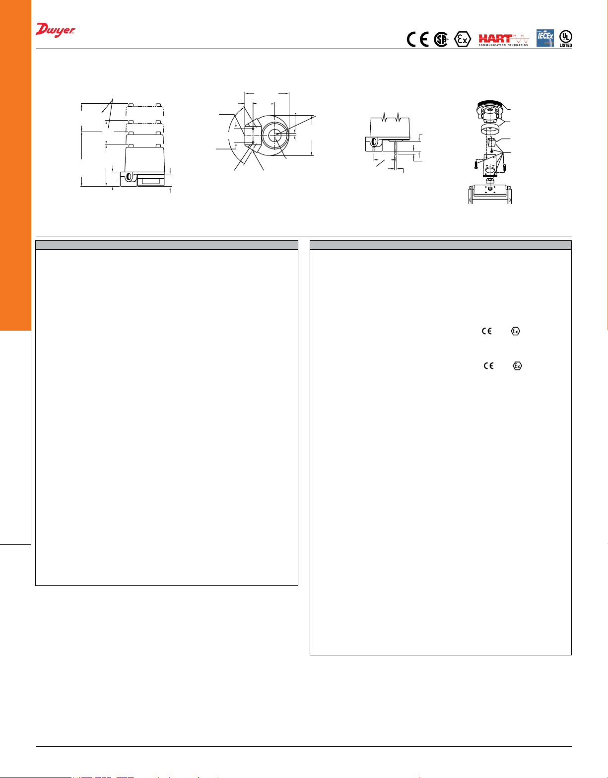
CLEARANCE REQUIRED
DIRECT DRIVE
[150.81]
LEVER DRIVE
4-7/8
SERIES MARK
POSITION INDICATORS/SWITCHES/TRANSMITTERS
VALVES
FOR COVER REMOVAL
4-1/4
[107.95]
[76.20]
4-9/16
[115.89]
5-15/16
[39.69]
3
1-9/16
OPEN
3/4 NPT
CONDUIT
CONNECTION
OR OPTIONAL
M25
1-1/4
[31.75]
7/8
[22.23]
[123.83]
2-3/8
[60.33]
118°
1-1/2
[38.10]
1/4-20 UNC
THREAD x
7/16 [11.11] DP
TYP 2 PLACES
1/2 NPT CONDUIT CONNECTION
For Models 11, 12, 41 and 42
1/4
#6-32 UNC
[6.35]
THREAD
TYP
X 1/4 [6.35]
DEEP
Ø4-7/16
[112.71]
Ø1/8 [3.18] PIN
TYP 2 PLACES
[OPTIONAL] OR OPTIONAL
M20 2 PLACES
2-3/8
[60.33]
.249 ± .001
[6.32 ± .03]
SWITCH
VISUAL
N
C
E
L
P
O
O
1-1/16
[26.99
5/16
[7.94]
S
INDICATOR
DRIVE
MOUNTING
KIT
SPECIFICATIONS
Mark 1, 3, and 4 with Potentiometer
Accuracy: ± 0.5% of full span. Optional ± 0.25% of full span.
Temperature Limits: -40 to 176°F (-40 to 80°C).(ameproof -B, -IE, and -BX sufx,
rated -40 to 145°F (-40 to 63°C) for switch types A, G, M, O, R, S, T, V, or W, -13 to
145°F (-25 to 63°C) for switch types B, D, or I.; intrinsically safe -IS, -II, -ISX sufx,
rated -13 to 104°F (-25 to 40°C) for switch type I, -40 to 104°F (-40 to 40°C) for
switch types O, R, S, V, or W.
Power Rating: 1.5 watt maximum.
Output Signal: 1000 Ω standard. Optional 2000, 5000, 10000, or 20000 Ω.
Zero and Span Adjustments: Span trim pot with 2000Ω adjustment. No zero
adjustment.
Rotational Travel: Mark 1 and 4: Minimum: 0°, Maximum: 340°. Mark 3: 0 to 10
revolutions.
Mark 1, 3, and 4 with Transmitter
Accuracy: ± 0.5% of full span. Optional ± 0.25% of full span.
Temperature Limits: -40 to 176°F (-40 to 80°C). (ameproof -B, -IE, and -BX sufx,
rated -40 to 145°F (-40 to 63°C) for switch types A, G, M, O, R, S, T, V, or W, -13 to
145°F (-25 to 63°C) for switch types B, D, or I.; intrinsically safe -IS, -II, -ISX sufx,
rated -13 to 104°F (-25 to 40°C) for switch type I, -40 to 104°F (-40 to 40°C) for
switch types O, R, S, V, or W.).
Power Requirements: 5-30 VDC.
Current Consumption: 50 mA.
Output Signal: 4-20 mA.
Zero and Span Adjustments: Trim pots for adjusting both. Mark 1 and 4: Span is
adjustable from 50 to 300°. Mark 3: Span is adjustable from 1.5 to 8.5 revolutions.
Conduit Connection: 3/4˝ female NPT standard. Optional one or two 1/2˝ female
NPT. M25 X 1.5 and M20 X 1.5 optional.
Rotational Travel: Mark 1 and 4: Min.: 50°, max.: 300°. Mark 3: Min.: 1.5
revolutions, max.: 8.5 revolutions.
Position Indicators/
Switches/Transmitters
Mark 1 and 4 Transmitter with HART
Accuracy: ± 0.5% of full span. Optional ± 0.25% of full span.
Temperature Limits: -40 to 176°F (-40 to 80°C). (ameproof -B, -IE, and -BX sufx,
rated -40 to 145°F (-40 to 63°C) for switch types A, G, M, O, R, S, V or W, -13 to
145°F (-25 to 63°C) for switch types B, D or I; intrinsically safe -IS, -II, -ISX sufx,
rated -40 to 104°F (-40 to 40°C) for switch types O, R, S, V or W; -13 to 104°F (-25
to 40°C) for switch type I.).
Power Requirements: 8-30 VDC.
Current Consumption: 21 mA.
Output Signal: 4-20 mA.
HART® Receive Impedance: Rx = 500 kΩ; Cx = 2500 pF.
Zero and Span Adjustments: Pushbuttons or HART® communication master for
setting both. Mark 1 and 4: Span is adjustable from 0 to 330°. Mark 3: Span is
adjustable from 1.5 to 8.5 revolutions.
Conduit Connection: 3/4˝ female NPT standard. Optional one or two 1/2˝ female
NPT. M25 X 1.5 and M20 X 1.5 optional.
Rotational Travel: Mark 1 and 4: Maximum: 330°.
®
Communication
SPECIFICATIONS
Product Ratings:
Weatherproof and ameproof. NEMA 1, 2, 3, 3R, 3S, 4, 4X, 6, 7, 9, 12, 13.
UL rated: class I, div. 1 and 2, groups B, C, D (some units available for group A,
consult factory); class II, div. 1 and 2, groups E, F, and G.
CSA rated: class I, div. 1 and 2, groups A, B, C, D; class II, div. 1 and 2, groups E,
F, and G. Submersible to 15 meters (IP68); It is up to the end user to source the
proper ttings to ensure a watertight seal.
ATEX Compliant:
-B sufx, directive 2014/34/EU, KEMA 03ATEX2391 X,
T6 Gb for -25°C/-40°C/-50°C ≤ Tamb ≤ 63°C and T5 for -25°C/-40°C/-50°C ≤ Tamb
≤ 63°C, optional wording depending on output and switch type selected. Compliant
per EN 60079-0, EN 60079-1.
-IS sufx, directive 2014/34/EU, KEMA 03ATEX1392 X, 2813 II 1G Ex ia IIC
T4 Ga. Compliant per EN EN 60079-0, EN 60079-11.
IECEx Compliant:
-IE sufx, IECEx DEK 11.0056X Ex db IIC T6 Gb for -25°C/-40°C/-50°C ≤ Tamb ≤
63°C and T5 for -25°C/-40°C/-50°C ≤ Tamb ≤ 63°C, optional wording depending on
output and switch type selected. Compliant per IEC 60079-0, IEC 60079-1.
-II sufx, IECEx DEK 11.0061X Ex ia IIC T4 Ga. Compliant per IEC 60079-0, IEC
60079-11, IEC 60079-26.
UKEX Compliant:
-BX sufx: DEKRA 21UKEX0274X, Ex db IIC T6 Gb for -25°C/-40°C/-50°C ≤ Tamb
≤ 63°C depending on output and switch type selected. Compliant per EN 60079-0
and EN 60079-1.
-ISX sufx: DEKRA 21UKEX0333X, Ex ia IIC T4 Ga, compliant per EN 60079-0 and
EN 60079-11.
Electrical Connections: Screw terminal. Optional factory sealed leads that are 36˝
(914.4 mm) of 16 AWG.
Conduit Connection: Standard: one 3/4˝ female NPT; optional one to two 1/2˝
female NPT; WirelessHART® models: two 1/2˝ female NPT; Optional: M25 X 1.5 or
M20 X 1.5 connections may be supplied in lieu of 3/4˝ and 1/2˝ female NPT for all
models.
Mounting Orientation: Not position sensitive.
Weight: 4 to 6 lb (1.5 to 3.0 kg).
Operational Life: Over 10,000,000 cycles.
Maximum Altitude: 2000 meters.
Mark 1, 3 and 4 with Switch Outputs
Temperature Limits: -58 to 176°F (-50 to 80°C). Switch type C rated to 350°F
(176°C) for 600 hours, switch type T rated to 250°F (121°C) continuous.
(ameproof -B, -IE, and -BX sufx, rated -58 to 145°F (-50 to 63°C) for switch type
A, G, H, T, or M, -40 to 145°F (40 to 63°C) for switch type O, R, S, V, or W, -13 to
145°F (-25 to 63°C) for switch type B, D, I, or AS Interface; intrinsically safe -IS, -II,
-ISX sufx, rated -13 to 104°F (-25 to 40°C) for switch type D or I, -40 to 104°F (-40
to 40°C) for switch type R, V, or W, or -58 to 104°F (-50 to 40°C) for switch type A,
G, or H.).
Switch Type: See page reference u below.
Electrical Rating: See page reference v below.
Set Point Adjustment: Mark 1 and 4: 5 to 360°.
2813 II 2G Ex db IIC
®
HART
is a registered trademark of Fieldcomm Group, Inc.
uSwitch Type: See page 435 (Series Mark)
vElectrical Rating: See page 435 (Series Mark)
DWYER INSTRUMENTS, LLC | dwyer-inst.com436
 Loading...