

Page 1
MADE IN
User’s Guide
Shop online at
omega.com
e-mail: [email protected]
®
For latest product manuals:
www.omegamanual.info
OMEGA USB SOFTWARE
Page 2

omega.com [email protected]
Servicing North America:
U.S.A.: Omega Engineering, Inc., One Omega Drive, P.O. Box 4047
Stamford, CT 06907-0047 USA
Toll-Free: 1-800-826-6342 (USA & Canada only)
Customer Service: 1-800-622-2378 (USA & Canada only)
Engineering Service: 1-800-872-9436 (USA & Canada only)
Tel: (203) 359-1660 Fax: (203) 359-7700
e-mail: [email protected]
Canada: Toll-Free: 1-800-826-6342 (USA & Canada only)
Servicing Mexico and Latin America:
Mexico/ Tel: 001 (203) 359-1660 Fax: 001 (203) 359-7700
Latin America: e-mail: [email protected] Web: mx.omega.com
Servicing Asia:
China: Hotline: (+86) 800 819 0559, (+86) 400 619 0559
e-mail: [email protected] Web: cn.omega.com
Servicing Europe:
France: Freephone: 0805 541 038 (France only)
Germany/Austria: Freephone: 0800 826 6342 (Germany only)
Italy: Freephone: 800 906 907 (Italy Only)
Netherlands: Freephone: 0800 099 33 44 (Netherlands only)
Benelux Tel: +31 070 770 3815 Fax: +31 070 770 3816
e-mail: [email protected] Web: www.omega.nl
Spain: Freephone: 800 900 532 (Spain only)
United Kingdom: Freephone: 0800 488 488 (United Kingdom only)
The information contained in this document is believed to be correct, but OMEGA accepts no liability for any errors it contains, and reserves
the right to alter specifications without notice.
WARNING: These products are not designed for use in, and should not be used for, human applications.
Page 3

Table of Contents
Section ........................................................................... Page
Section 1 - Introduction ..................................................... 1-1
1.1 Precautions ................................................................................................ 1-1
1.2 Safety Warnings and IEC Symbols ......................................................... 1-1
1.3 Statement on CE Marking ....................................................................... 1-2
1.4 General Description .................................................................................. 1-2
Section 2 - Hardware ....................................................... 2-1
2.1 Package Inspection ................................................................................... 2-1
Section 3 - Software ......................................................... 3-1
3.1 Getting Started .......................................................................................... 3-1
3.2 System Requirements ............................................................................... 3-1
3.3 Software Installation ................................................................................ 3-1
3.4 Using Omega USB Software ................................................................... 3-7
Table of
OMEGA USB SOFTWARE
Contents
1.3.1 CE Marking ...................................................................................... 1-2
1.4.1 General Description ........................................................................ 1-2
3.2.1 System Requirements....................................................................... 3-1
3.4.1 Overall Program Structure ............................................................. 3-8
3.4.2 Channel Config Window ................................................................ 3-9
3.4.3 Channel Window ........................................................................... 3-14
3.4.4 Miscellaneous ................................................................................. 3-16
3.4.5 Logging Window ........................................................................... 3-17
Section 4 - Troubleshooting ............................................... 4-1
i
Page 4

Table of
Figures
OMEGA USB SOFTWARE
Table of Figures
Figure Description Page
1-1 IEC Symbols ................................................................................. 1-1
3-1 Welcome Window ........................................................................ 3-2
3-2 Install Options Window .............................................................. 3-2
3-3 Select Installation Folder Window ............................................ 3-3
3-4 Disk Cost Window ....................................................................... 3-3
3-5 Confirm Installation Window .................................................... 3-4
3-6 License Agreement Window ....................................................... 3-4
3-7 Software Installation Window ................................................... 3-5
3-8 Device Driver Confirmation Window ....................................... 3-5
3-9 Device Driver Installation Window .......................................... 3-6
3-10 Device Driver Completion Window ........................................ 3-6
3-11 Installation Complete Window .................................................. 3-7
3-12 Program Launch .......................................................................... 3-7
3-13 Program Launch Splash Window .............................................. 3-7
3-14 Sensor Activity Window ............................................................. 3-8
3-15 Channels Window ....................................................................... 3-8
3-16 Configuration Confirmation Window ...................................... 3-9
3-17 Channel Config Window .......................................................... 3-10
3-18 Deadband Example ................................................................... 3-13
3-19 Channels Tab .............................................................................. 3-14
3-20 Channels Window Detail .......................................................... 3-15
3-21 User Alarm Annunciation in Channels Window .................. 3-16
3-22 Overload Alarm Annunciation in Channels Window .......... 3-17
3-23 Overload Alarm Annunciation During Repeat Overload ... 3-17
3-24 Logging Window ....................................................................... 3-18
3-25 Choose Logging Base Filename Window ............................... 3-18
ii
Page 5
Section 1 - Introduction
Please read this manual completely before installing and operating your USB
Sensor. It’s important to read and follow all notes, cautions, warnings and safety
precautions before operating this device.
1.1 Precautions
• This device is not designed for use in medical or nuclear applications.
• Do not operate this device in flammable or explosive environments.
• Do not operate this device outside of the recommended use outlined in this
manual.
There are no user serviceable parts inside your device.
Attempting to repair or service your unit may void your
warranty.
NOTE:
Introduction
1
1.2 Safety Warnings and IEC Symbols
This device is marked with international safety and hazard symbols in
accordance with IEC 1010. It is important to read and follow all precautions and
instructions in this manual before operating or commissioning this device as it
contains important information relating to safety and EMC. Failure to follow all
safety precautions may result in injury and/or damage to your device. Use of
this device in a manner not specified may void your warranty.
IEC symbols Description
Caution, refer to accompanying
documentation.
Waste Electrical and Electronic Equipment
Compliance
Figure 1-1. IEC Symbols
1-1
Page 6

1
Introduction
1.3 Statement on CE Marking
1.3.1 CE Marking
It is the policy of OMEGA to comply with all worldwide safety and EMI/EMC
regulations that apply. OMEGA is constantly pursuing certification of its
products to the European New Approach Directives. OMEGA will add the CE
mark to every appropriate device upon certification.
1.4 General Description
1.4.1 General Description
Omega USB is free user software that converts your PC into a data meter with
digital display and data logging.
1-2
Page 7

Section 2 – Hardware
It is important that the user read this manual completely and follow all safety
precautions before operating this instrument.
Only Omega PX409-USBH sensors are compatible with this software.
2.1 Package Inspection
Remove the packing list and verify that all equipment is included. If
there are any questions about the shipment, please call the Omega Customer
Service Department at 1-800-622-2378 or 203-359-1660. Omega can also be
reached on the Internet at www.omega.com, e-mail: [email protected]
When the shipment arrives, inspect the container and equipment for any signs of
damage. Note any evidence of rough handling in transit. Immediately report any
damage to the shipping agent.
NOTE:
Hardware
2
The carrier will not honor any damage claims unless all the
shipping material is saved for inspection. After examining
and removing the package contents, save the packing
material and carton in the event that reshipment is necessary.
2-1
Page 8

3
Software
Section 3 – Software
3.1 Getting Started
Important: Do not connect the Omega USB sensor into the computer until the
software and FTDI driver has been installed.
The following program files are included on the Omega User Software CD
supplied with the sensor. These files can also be downloaded from the
omega.com website.
• Omega USB Software
• Omega USB Software Manual (pdf format)
• Sensor Command Reference
• Labview Vis and examples
• .NET drivers
3.2 System Requirements
3.2.1 System Requirements
The PC should meet the following minimum requirements:
• Pentium IV or higher processor
• Hard Drive Space: 50MB for software. For logging: 50kB per 1000 samples
times the number of channels.
• RAM: 1GB
• 1 Available USB 2.0 Port
• 1 CD-ROM Drive
• Windows XP Service Pack 3 or later
3.3 Software Installation
Insert the CD that was included with the unit into the CD-ROM drive of the PC.
The installation process should begin automatically. If it doesn’t begin
automatically, navigate to the CD-ROM drive and double click on “setup.exe”.
3-1
Page 9
Software
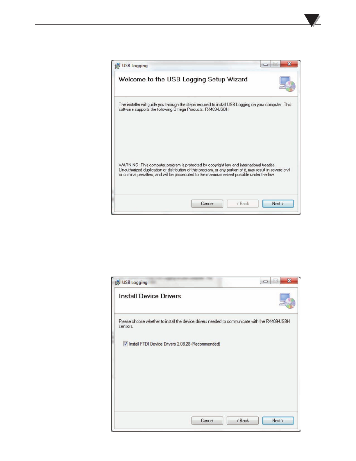
The welcome dialogue box should be visible on the computer screen. To
continue installing the program, click the “Next >” button.
3
Figure 3-1. Welcome Window
The “Install Options” dialogue box should be visible on the computer screen. If
FTDI drivers have not been installed on the PC, or if the FTDI version installed
on the PC is old or unknown, keep the checkbox checked next to “Install FTDI
Device Drivers _______ (Recommended)”. If the latest drivers are already
installed, uncheck the check box. To continue with the program installation,
click the “Next >” button.
Figure 3-2. Install Options Window
3-2
Page 10
3
Software
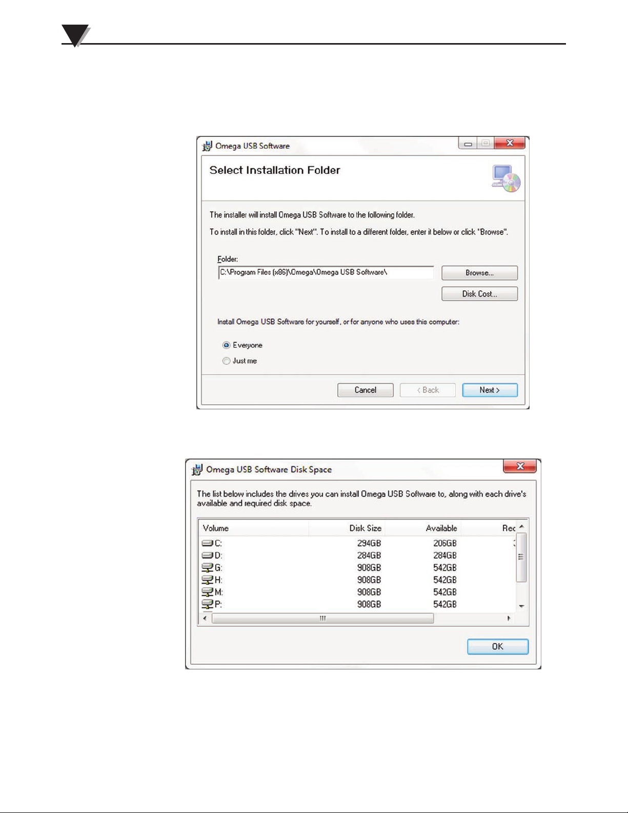
From the “Select Installation Folder” dialogue box, select the desired folder
where the program files will be installed on the PC. The default setting will
install the software in a new folder named “Program Files\ Omega\USB
Logging”. To continue with installing the program, click the “Next >” button.
Figure 3-3. Select Installation Folder Window
Optionally, the Disk Cost can be obtained by pressing the Disk Cost button
Figure 3-4. Disk Cost Window
3-3
Page 11
Software
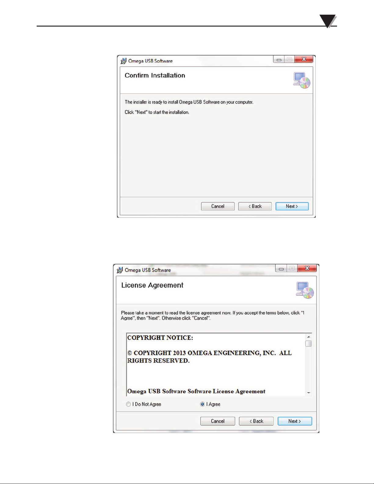
To continue with installing the program, click the “Next >” button.
3
Figure 3-5. Confirm Installation Window
From the “License Agreement” dialogue box, “I Agree” must be selected to
continue with the program installation. “Cancel” will stop the installation. After
making the selection, click the “Next >” button.
Figure 3-6. License Agreement Window
3-4
Page 12
3
Software
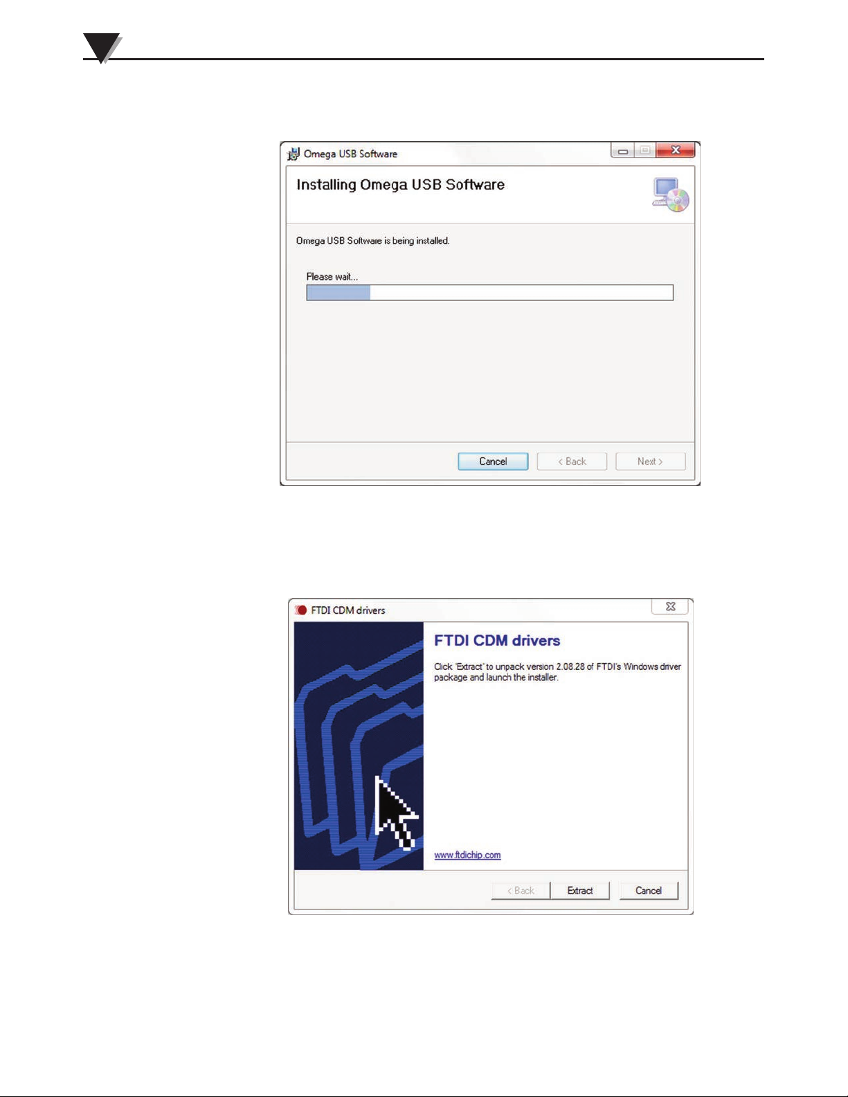
The setup wizard now has all the needed information and will complete the
installation of the software on the PC.
Figure 3-7. Software Installation Window
During the install process, if the “Install FTDI Device Drivers” checkbox was
selected in a previous step, the setup wizard will now install the proper drivers.
To continue installing the program, click the “Extract” button.
3-5
Figure 3-8. Device Driver Confirmation Window
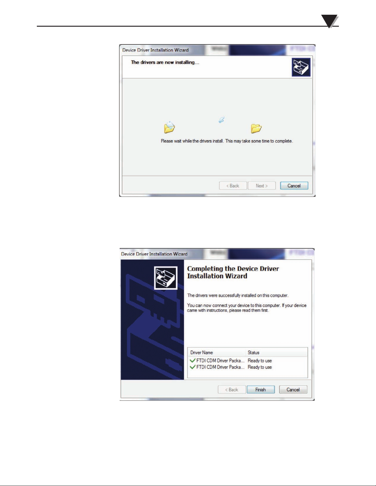
The driver installation will begin.
Page 13
Software
3
Figure 3-9. Device Driver Installation Window
After the installation wizard completes installing the drivers, the following
window should be seen on the computer screen. To finish, click the “Finish”
button.
Figure 3-10. Device Driver Completion Window
The Omega Program has now been successfully installed on the PC.
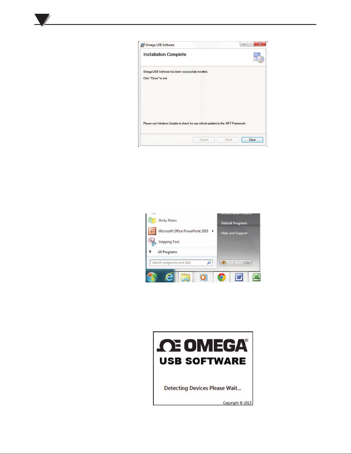
Close the setup wizard by clicking the “Close” button.
3-6
Page 14
3
Software
3.4 Using Omega USB Software
To launch the Omega program, begin by accessing the “All Programs” list under
the “Start Menu”. Next, scroll through the list of program folders to find the
“Omega” folder. Inside the “Omega” folder, click on the “USB Logging”
program link. This will begin running the program. Alternatively, the install
program creates an icon on the desktop, which can be used to start the program.
Figure 3-11. Installation Complete Window
3-7
Figure 3-12. Program Launch
When the program is started, a Splash window will appear and persist until all
connected sensors are detected. This takes approximately 5 seconds per attached
sensor, depending on the computer performance and other processes that are
running.
Figure 3-13. Program Launch Splash Window
Page 15
Software
3
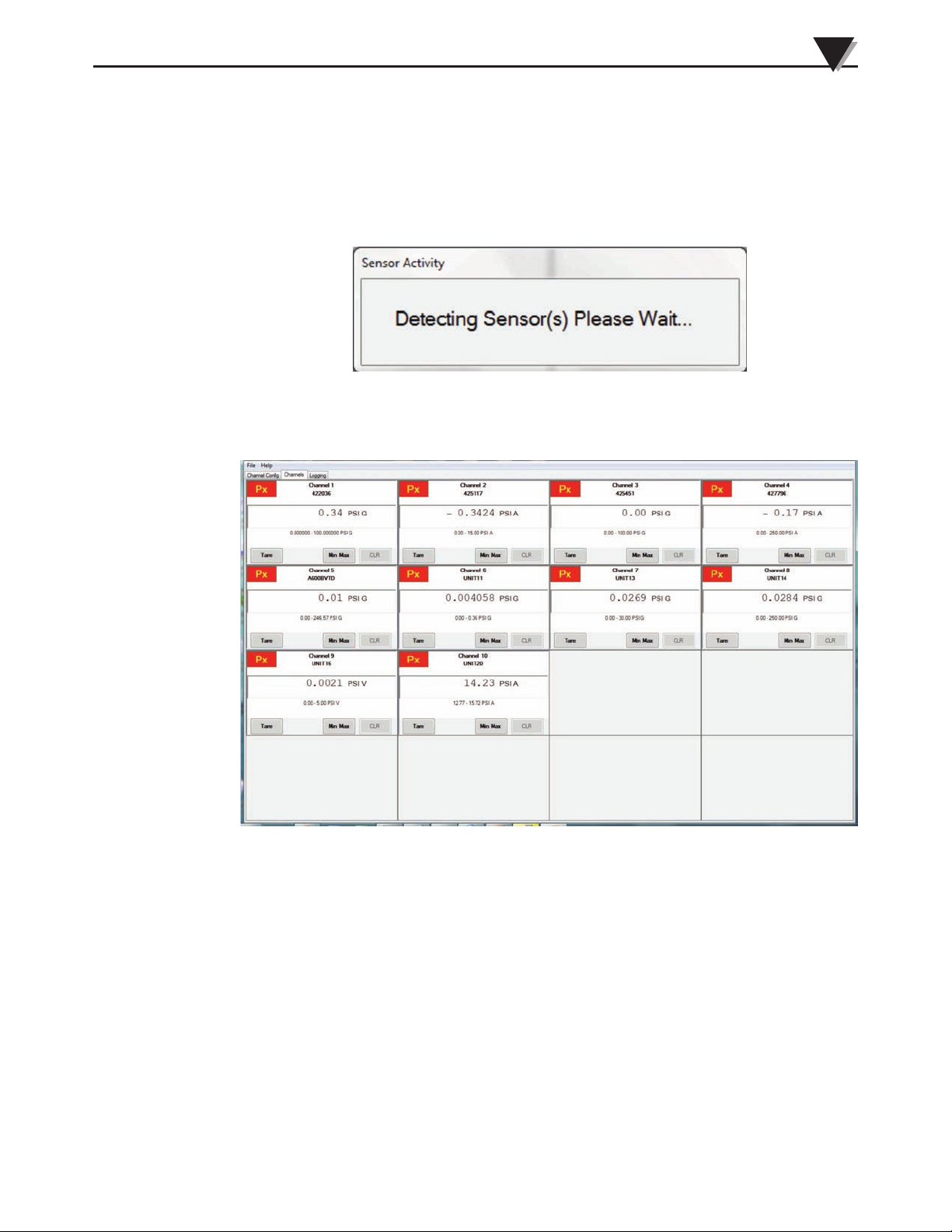
Connect one or more sensors to an available USB 2.0 port on a computer. A
“Sensor Activity” window will appear while the program is detecting the
connected sensors. If a sensor is not recognized, view the Troubleshooting area
of this manual for help on this topic. Each sensor that is connected takes
approximately 5 seconds for detection, depending on the computer performance
and other processes that are running.
Figure 3-14. Sensor Activity Window
The default window is the Channels window:
Figure 3-15. Channels Window
3.4.1 Overall Program Structure
The Omega program uses a tabbed structure for setting up the sensors and
configuring/viewing the data. Clicking on the Channel Config, Channels, or
Logging tab opens the respective windows.
• Channel Config window: The location where all the parameters are set up for
each sensor, such as sample rate, filters, etc. These parameters impact how
information is displayed or recorded by the functionality of the other two
tabs.
• Channels window: A grid of zero to twelve channels that display a digital
readout of the sensor output.
• Logging window: Data for up to 12 sensors is stored in individual .csv files for
post analysis.
3-8
Page 16
3
Software
3.4.2 Channel Config Window
The Channel Configuration Window controls all of the channel-specific
parameters, and some global parameters. Some parameters are changeable
elsewhere. Only sensors that are connected to the computer will be present in
the Channel Config window. The following describes the content of the
Configuration Window cells. Defaults will be applied to sensors which have not
been connected before. After configuring a sensor, the software will retain the
sensor settings that are present when the sensor is disconnected or when the
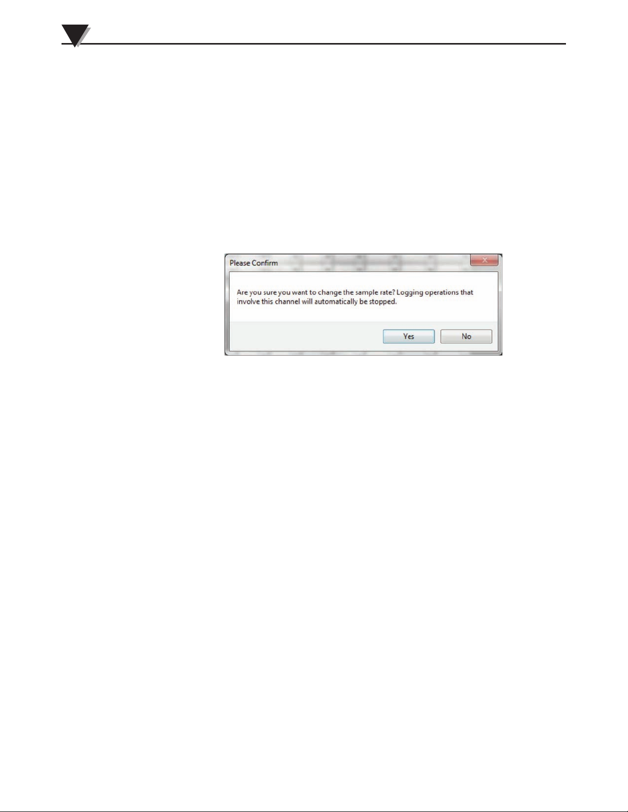
program is closed. If changes are made to rows 5, 7, 8, 11, and 13-16 while the
sensor is being logged, this will result in a Yes/No prompt box appearing: “Are
you sure you want to change the _______? Logging operations that involve this
channel will automatically be stopped.” Clicking “Yes” will apply the change,
clicking “No” will revert back to the value before the change.
Figure 3-16. Configuration Confirmation Window
3-9
Page 17
Software
3
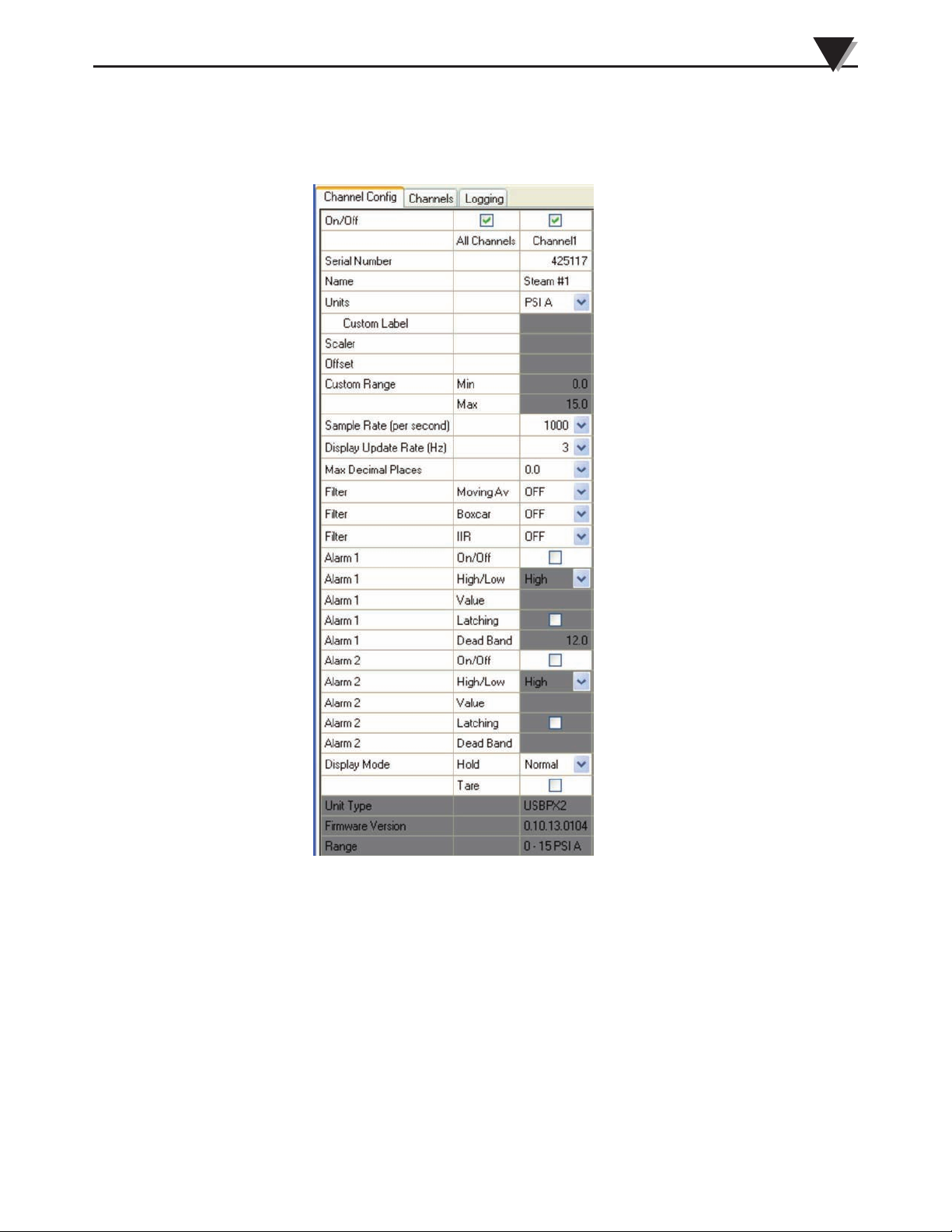
The screenshot below shows the Channel Configuration window with one sensor
connected to channel 1. The numbers next to each row exist only in this manual, not
in the software program itself. The descriptions below refer to the numbered rows.
1
2
3
4
5
6
7
8
9
10
11
12
13
14
15
16
17
18
19
20
21
22
23
24
25
26
27
28
29
30
31
Figure 3-17. Channel Configuration Window
1) Row 1 – Channel on/off
Clicking each box turns all channels or individual channels on and off. When a
channel has a sensor that is connected but turned off, the entire column will be
grayed out. When a channel is on, editable fields will become a light color. The
channel on and off status only affects the channel window (it does not affect the
Logging window, except for removing that particular channel as selectable for
logging).
All Channels
Checking or unchecking the box above “All Channels” turns on and off every
channel where a sensor is connected. If there is a mixture of sensors that are on
and off, the box will be grayed out. In this grayed out state, clicking the box will
turn on the channels that were previously off. Clicking the box again will turn
off all channels.
3-10
Page 18

3
Software
Individual Channels
If a sensor is connected, checking or unchecking the box above each channel
turns on and off that specific channel. When a sensor is connected, the channel
will automatically turn on. When a sensor is disconnected, the channel will turn
off automatically.
2) Row 2 – Channel number
Indicates the channel number for each column.
3) Row 3 – Serial number
Displays sensor serial numbers for sensors that are connected whether the
channel is off or on.
4) Row 4 – Channel Name
The user can assign a descriptive name for the channel in this box, up to 20
characters and spaces. The default is blank.
5) Row 5 – Engineering Units
Clicking on the drop down box allows the user to choose from other engineering
units that will be applied to Channels and Logging windows. The user can select
from a standard list of engineering units (the default is the units assigned to the
sensor), or “CUSTOM”, where user can type a custom label in row 6, and specify
scalar and offset in rows 7-8. Scalar and Offset are applied in that order. Only
standard engineering units within the same type of sensor are selectable. For
example, PSI G (gage) cannot be changed to mbar A (absolute).
6) Row 6 – Custom Label
When “Custom” units are specified in Row 5, this box will be editable, and the
user can type text up to 4 Characters/Spaces. This text will appear in the
channels window next to the digital readout, and next to the recalculated sensor
range. The default is blank.
7) Row 7-8 – Scalar and Offset
When “Custom” units are selected in row 6, the numbers entered in the scalar
and offset fields will modify the output of the sensors by applying a unit
conversion, and the result is applied to channel and logging windows. The order
of operations is: Output = (scalar * sensor output) + offset. The scalar and offset
can be positive or negative. The maximum value that can be entered is 11
significant figures. The default is blank, i.e. no effect (equates to a one for scalar
and a zero for offset). The user alarms are affected by the scalar and offset values
as indicated in “ 13) Row 17-21 and 22-26 – User Alarms”.
8) Row 9-10 – Custom Range
When “Custom” units are selected in row 6, and a scalar and/or offset value is
entered in Rows 7-8, the new sensor min/max range will be displayed, which is
the sensor’s native range, modified by the scalar and offset. The custom range
boxes are grayed out if “Custom” is not selected in row 5, and will display the
range of the native units of the sensor.
9) Row 11 – Sample Rate
The sample rate specifies the number of samples per second that the data will be
acquired from the sensor. The sample rate is selectable from the drop down box
with the following choices: {5, 10, 20, 40, 80, 160, 320, 640, 1000} samples per
second (5 to 1kHz). The actual sample rate can vary by the sensor’s sample rate
tolerance.
3-11
Page 19

Software
3
10) Row 12 – Display Update Rate
The display update rate, in Hz, is user defined, and specifies the update rate for
the digital readout in the Channels window. Values between one and ten are
selectable from a drop down box. The default is 3Hz.
11) Row 13 – Maximum Decimal Places
Sets the maximum number of decimal places that are shown on the sensor
readings in the channel window.
12) Row 14-16 – Filters
The filter values specify the amount of filtering that is applied to the data in the
corresponding channel. The filters affect the data that is displayed in both the
Channels and the Logging windows. Filters can be used in combination. The
filter application order is: 1) Moving Average, 2) IIR, 3) and Boxcar, where the
output of each filter is the input to the next filter. Note that if advanced filtering
is desired, all of these filters can be disabled (OFF), the data logged, and post
processing can be done on the logged data. Note that increased filter values
decrease the response time of the indicated output. The filters must be set
according to the desired sensitivity.
a) Row 14 - Moving Average Filter
The moving average filter is a simple averaging filter that adds the number of
samples specified by the value set in this box, and divides by the value set in
this box. Before each calculation, the oldest sample is subtracted, the new
sample is added, and a new calculation is done. This filter is effective at
filtering noisy signals, but not impulse signals. Selectable values are: MA OFF
(disabled), and two through 63.
b) Row 15 – Boxcar Filter
The boxcar filter takes a number of readings, averages them, then outputs one
reading for the entire group. This is the only filter that modifies the sample
rate of the sensor. The net sample rate is the value entered in row 11 divided
by row 15. Selectable values are: Boxcar OFF (disabled), 2, 4, 8, and 16.
c) Row 16 – Infinite Impulse Response filter
Calculation: Output previous filtered reading + ((new raw reading – previous
raw reading)/n where n = the number entered in the Row 16 box. The “n”
value effectively is the weighting that the new reading has on the output of
the filter. Selectable values are: IIR OFF (disabled), two through 63.
13) Row 17-21 and 22-26 – User Alarms
There are two independent Alarms that can be enabled. The alarms impact the
channel window only, and are user configurable according to the settings
described below. When an alarm is annunciating, the window will flash yellow
or red (depending on the entries in rows 18/23), along with flashing “High” or
“Low” text (matching the setting in row 18/23). The user alarm thresholds
default to the sensor’s native range.
a) Row 17/ 22 – User Alarm on/ off.
Enables/disables alarm 1 and 2. Settings are retained after turning off an
alarm (alarm rows are grayed out, but still show values, and can still be
changed), and remain after the alarm is turned on. Alarms are not
annunciated in the Channels window when a sensor’s channel is turned off.
3-12
Page 20
3
Software
b) Row 18/23 – User Alarm High/Low
Configures alarm as low or high alarm (low meaning alarm triggers as value
passes from high to low through the alarm setting, high meaning that the
alarm triggers as value passes from low to high through the alarm setting).
Select with drop-down box. If both alarms are set to low or to high, a two
stage alarm can be configured. When passing the first threshold, the flashing
window will be yellow, and passing the second threshold will produce a red
flashing window.
c) Row 19/24 – User Alarm Threshold Value
The user-defined value, which triggers the user alarm when the sensor output
is above or below the value (determined by Row 18/23). This value is
automatically recalculated by the software when the engineering units are
changed (either to standard or custom). Valid values are up to the Overload
Alarm setting (usually 10% above/below the upper/lower range of the
sensor).
d) Row 20/25 – Latching
User can enable or disable latching for each user alarm. If latching is enabled,
the user alarm continues to annunciate when the sensor output returns from
(user) alarm triggered to a non-triggered value.
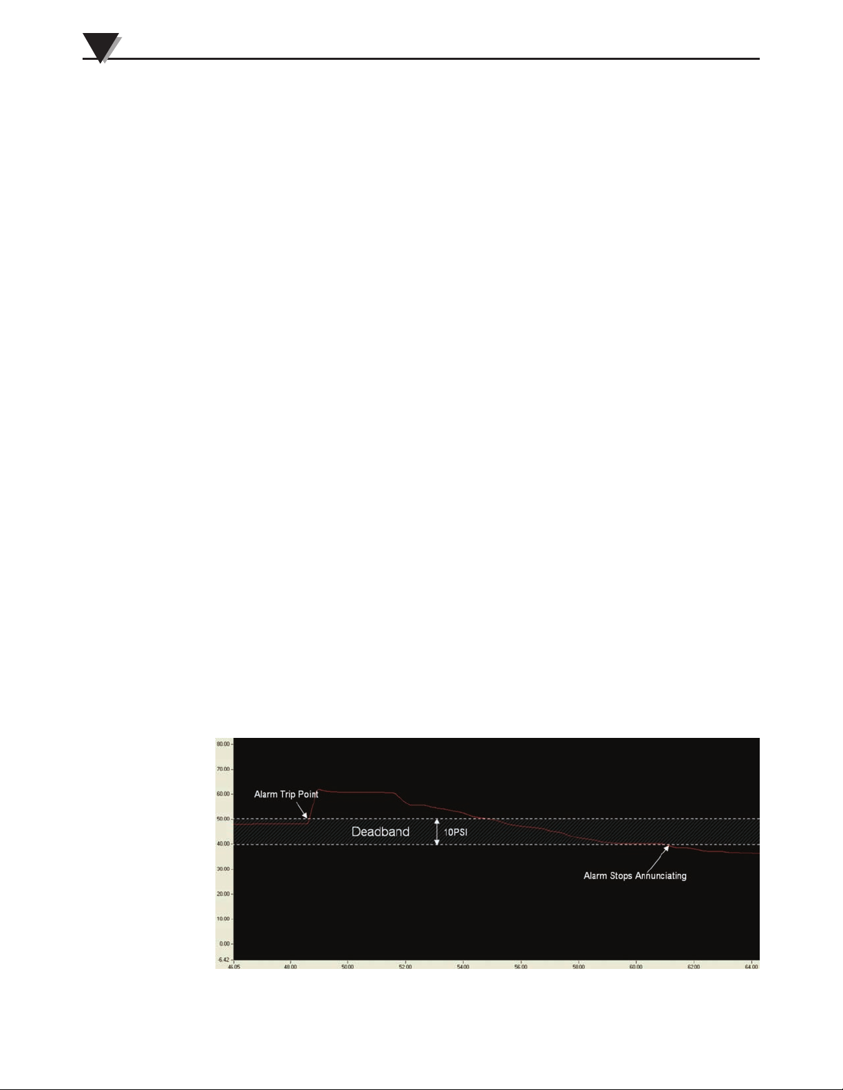
e) Row 21/ 26 – Deadband
The Deadband provides hysteresis to prevent flickering alarm conditions
when the sensor output is near the alarm limit. The Deadband region is user
selectable, and is an absolute value. If an alarm is configured as a high alarm,
the alarm will be triggered as it increases above the value specified by Row
19/24, but annunciation of the alarm will not stop until the sensor output
drops below the alarm value minus the Deadband value. Likewise, for an user
alarm configured as a low alarm, the user alarm will be triggered as it falls
below the value specified by Row 19/24, but annunciation of the user alarm
will not stop until the senor output rises above the user alarm value plus the
Deadband value. If latching is selected (Row 20/25), the Deadband will be
grayed out and not editable. The Deadband value must be positive, and
cannot be greater than the sensor range. Using the diagram below as a
graphical example, the high user alarm threshold is 50 PSI, and the Deadband
is 10PSI. If the sensor output triggers the alarm at 50PSI, the user alarm will
continue to annunciate until the sensor drops below 40PSI.
3-13
Figure 3-18. Deadband Example
Page 21
Software
NOTE:
3
Changes to Scalar and Offset will affect the user alarms in
the following manner:
1) If the scalar value is inverted: High/Low user alarm inverts
(High becomes Low, Low becomes High).
2) If the scalar value is other than 1: The user Alarm values
are multiplied by the scalar value.
3) If the offset value is other than 0: The user alarm values are
offset by the offset value.
14) Row 27 – Max/Min Hold
User selectable hold display mode (affects Channels window only). Min/Max
hold, and normal (no hold) are the choices in the drop down box. Each channel
has a separate Min/Max value, and recording begins when the channel is turned
on, and flushed when the channel is turned off or disconnected. Min and Max
are constantly being stored regardless of the value of this selection box.
15) Row 28 – Tare
Tare is an offset applied to the sensor output, and displayed in the Channels
window, and in the logged data. The offset is calculated and subtracted from the
sensor output when the tare button is pressed, resulting in a zero sensor reading
at the instant when the tare button is pressed. A check in the box means that the
Tare is applied, and no check means Tare is not applied. Each time the tare
button is unchecked and checked, a new tare value is calculated and applied.
The Tare affects values stored in the channels window, and also the logged data.
It is advisable to not use the Tare function during logging. The tare value is
stored in temporary memory, and is erased when power is removed from the
unit.
16) Row 29 – Unit Type
The Unit type is a Factory specified code, and is not changeable by the user.
17) Row 30 – Sensor Firmware Version
18) Row 31 – Range
The range of the sensor in the original engineering units before any conversions
are applied.
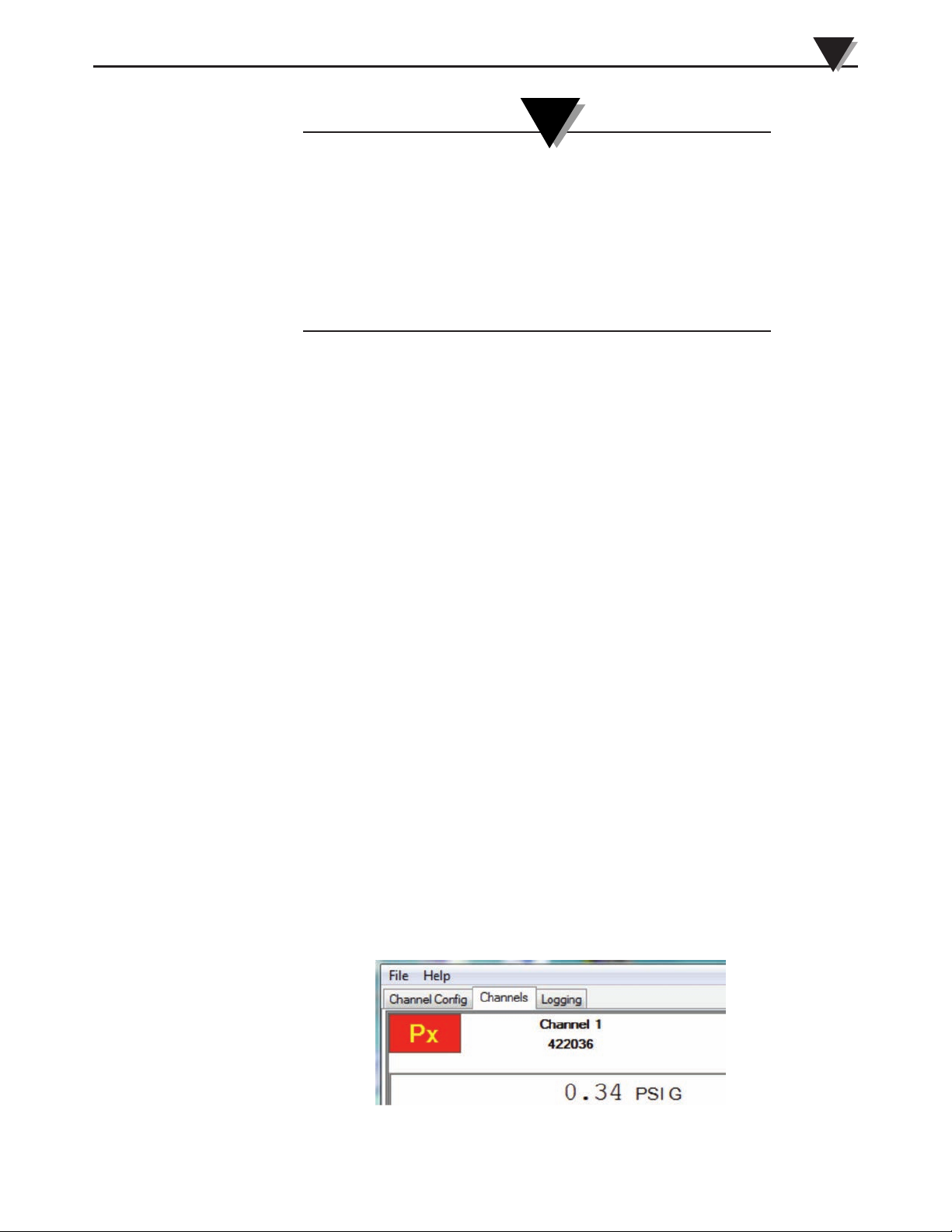
3.4.3 Channels Window
The Channels Window shown below is the default window that is displayed
when you run the program. This window provides a real-time digital reading of
sensor output when used with the PX409-USBH family.
Figure 3-19. Channels Tab
3-14
Page 22
3
Software
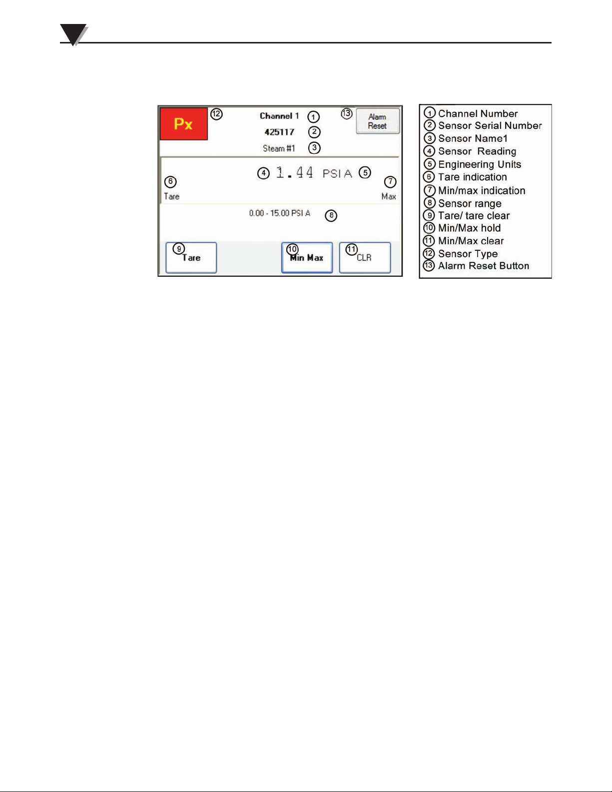
The view below is an example of one channel of the Omega Program in normal
operation:
Figure 3-20. Channels Window Detail
1) Channel Number - There is a maximum of twelve channels.
2) Sensor Serial Number
3) Sensor Name - User configurable description
4) Sensor Reading - Output of the sensor
5) Engineering Units - The type of engineering units. Can be the sensor’s native
engineering units, or custom engineering units as specified on the channel config
window.
6) Tare indication - If the Tare is applied, “Tare” will be visible, with the value of
the offset applied.
7) Min/max indication - If the Minimum or Maximum hold value is selected,
“Min” or “Max” will be visible.
8) Sensor range - Displays either the sensor’s native engineering units, or if
“Custom” engineering units are selected in the Channel Config window, this
area will contain the new calculated range.
9) Tare/ tare clear - Pressing this button toggles the Tare on and off. Default is
off.
10) Min/Max hold - Pressing this button rotates between the hold modes Min,
Max, and off. Default is off.
11) Min/ max clear - Clears the value stored in Min or Max (whichever is
currently displayed).
3-15
12) Sensor type - PX = Pressure Sensor, LX = Load Sensor.
13) User “Alarm Reset” Button – if the sensor’s value drops below the threshold
of a latched user alarm (1 and/or 2), this button will appear. If the threshold of
the latched user alarm is again exceeded before the user “Alarm Reset” button is
pressed, the user “Alarm Reset” button will not be visible, and the user alarm
will continue to annunciate. Pressing the user “Alarm Reset” button (when
visible) will clear the user alarm.
Page 23
Software
3
Channels Window Special Cases
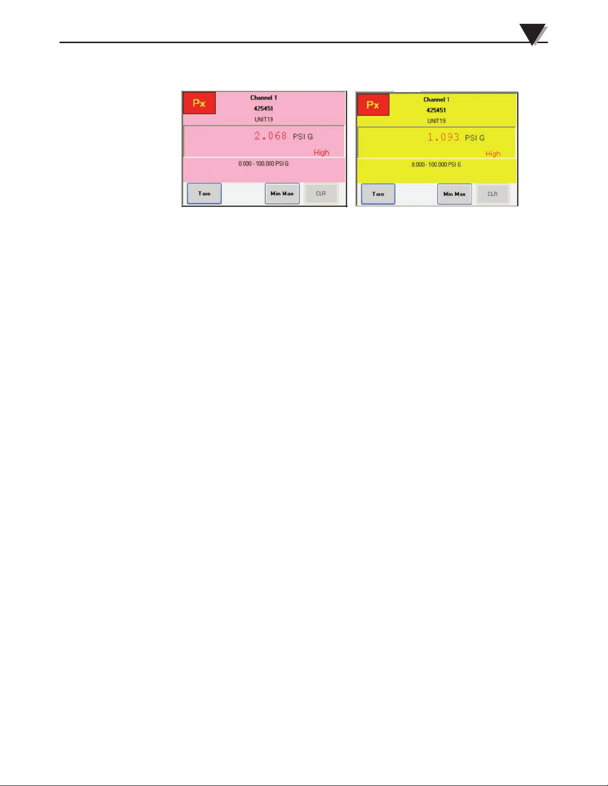
Figure 3-21. User Alarm Annunciation in Channels Window
1) User Alarm Annunciation (case where only one user alarm is set, or both user
alarms are set and are opposite high/low values): When a sensor output has
exceeded/receded above/below the user alarm threshold as specified in the
Channel Config window, the channel window will change to a flashing red color,
with “High” or “Low” being flashed (depending on if a High or Low Threshold
has been exceeded). If the sensor output returns to a value outside the alarm
threshold, AND latching is off, the alarm will stop annunciating. If the sensor
output returns to a value outside the alarm threshold, AND latching is on, an
Alarm Reset button will appear, and the alarm will continue to annunciate until
this button is pressed.
2) User Alarm Annunciation (case where both user alarms are set and are the
same type, high/low): When a sensor output has exceeded or receded
above/below the first user alarm threshold as specified in the Channel Config
window, the channel window will change to a flashing yellow color, with
“High” or “Low” being flashed (depending on if a High or Low Threshold has
been exceeded). If the sensor value continues into the second user alarm
threshold value, the window will change to a red flashing color. If the sensor
value changes back to between the two thresholds, (and latching is off), the
flashing window color will change back to yellow. If the sensor value changes
below/above the first low/high threshold (and latching is off), then the user
alarm will stop annunciating. If latching is ON, the highest user alarm that was
previously tripped will remain flashing until the user “Alarm Reset” button is
pressed.
3.4.4 Miscellaneous
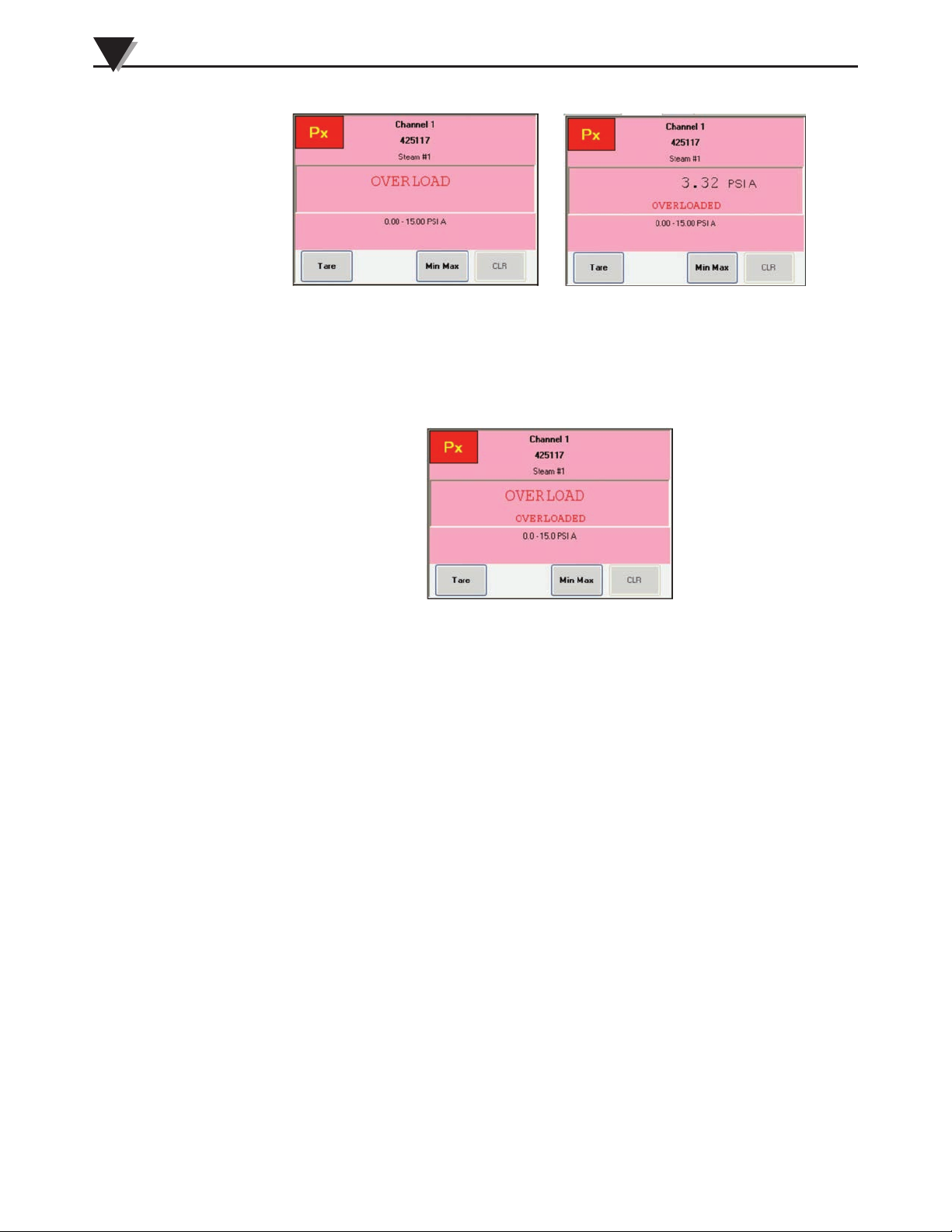
1) Overload alarm. Each sensor is factory configured with an overload alarm.
The value of the overload alarm varies between each sensor type/range, but it is
above and below the upper and lower range values of the sensor. When the
overload alarm is tripped, the box will change to a solid red, and the sensor
reading will change to the word “OVERLOAD” while the overload is still
applied to the sensor. When the sensor output has returned outside the overload
alarm threshold, the sensor reading will be displayed again, but the window will
remain red, and “OVERLOADED” will appear in the lower area of the readout
window, and will remain until the sensor is disconnected, or the program is
closed.
3-16
Page 24
3
Software
Figure 3-22. Overload Alarm Annunciation in Channels Window
If the sensor output enters the Overload range again, “OVERLOAD” and
“OVERLOADED” text will be displayed simultaneously. When the sensor
output returns outside the Overload range, “OVERLOAD” will disappear, but
“OVERLOADED” will remain.
Figure 3-23. Overload Alarm Annunciation During Repeat Overload
3.4.5 Logging Window
The Logging window enables logging of the data for a maximum of 12
connected sensors. The sensors can be any combination of samples per second
and Engineering Units. The parameters of the data collected by the logging
function are adjusted by the Channel Config window.
3-17
Page 25
Software
3
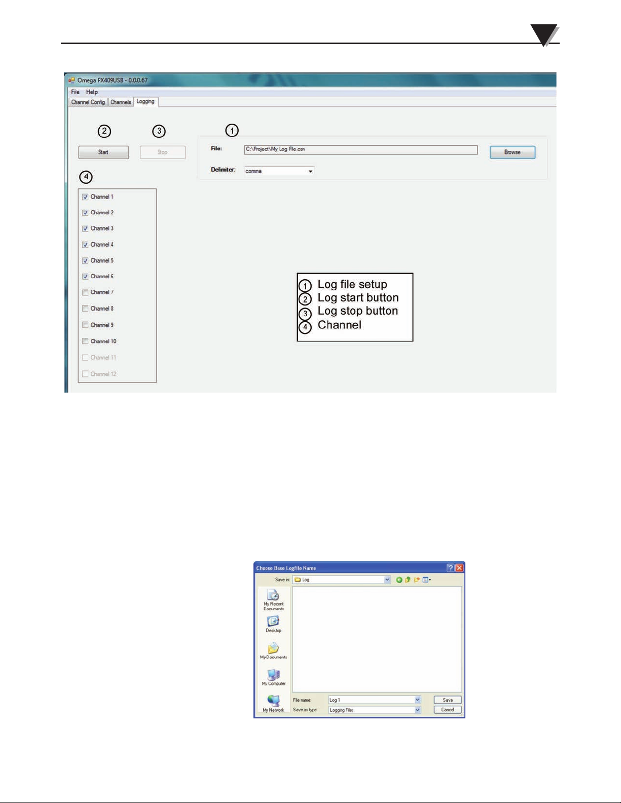
Figure 3-24. Logging Window
Description of Logging Window Elements
1) Logging file setup
Specify the file location for the log file to be stored. Press the Browse button to
open the Choose Base Logfile Name box, browse for the file location, and enter a
name for the .csv file. Choose Comma or Tab delimiting. If the logging file
already exists, a prompt will appear: “The file {path} already exists, would you
like to replace it?” Clicking “Yes” will replace the file, clicking “No” will return
to the “Choose Base Logfile Name” box. Note that individual .csv files will be
created for each channel, with a suffix “-channelxx“ added to the base file name,
where “xx” is the channel number.
Figure 3-25. Choose Logging Base Filename Window
3-18
Page 26

3
Software
2) Logging start button
Pressing the “Start” button will start the logging of the selected channels to the
selected file location. The “Start” button will then be grayed out and
unselectable, and the “Stop” button will become active. Changes are permitted
to all parameters in the Channel Config window; However, for most
configurable items, a pop up box will warn the user that changes to that item
require that the logging operation is stopped. Pressing “Yes” will stop logging
and apply the parameter change, pressing “No” will continue logging and
disregard the parameter change.
3) Logging stop button
Halts the current logging operation
4) Logging channel selection
Select which channels are available to be logged. Only channels that are
connected and turned on will be selectable. No changes are allowed while
logging is taking place.
3-19
Page 27

Section 4 – Troubleshooting
1) Sensor is not recognized by the software program
Checkpoints:
a) Disconnect the sensor from the USB port of the computer, wait 5 seconds, then
connect the sensor.
b) Verify that the latest FTDI driver is installed on the computer. If not,
disconnect all sensors, and update to the latest driver from FTDI
(http://www.ftdichip.com/Drivers/D2XX.htm). It is recommended to choose
the executable driver under the Comments field for best results.
2) The Data is noisy
a) Reduce the sample time. Faster sample rates have more inherent noise.
b) Reduce the number of decimal places shown if the current resolution is not
needed.
c) Filter the data with the Moving Average, IIR, and/or the boxcar filters. Note
that this decreases response time of the sensors to fast moving inputs to the
sensor.
Troubleshooting
4
4-1
Page 28

NOTES:
OMEGA USB SOFTWARE
4-2
Page 29

NOTES:
OMEGA USB SOFTWARE
4-3
Page 30

NOTES:
OMEGA USB SOFTWARE
4-4
Page 31

WARRANTY/DISCLAIMER
OMEGA ENGINEERING, INC. warrants this unit to be free of defects in materials and workmanship for a
period of 13 months from date of purchase. OMEGA’s WARRANTY adds an additional one (1) month
grace period to the normal one (1) year product warranty to cover handling and shipping time. This
ensures that OMEGA’s customers receive maximum coverage on each product.
If the unit malfunctions, it must be returned to the factory for evaluation. OMEGA’s Customer Service
Department will issue an Authorized Return (AR) number immediately upon phone or written request.
Upon examination by OMEGA, if the unit is found to be defective, it will be repaired or replaced at no
charge. OMEGA’s WARRANTY does not apply to defects resulting from any action of the purchaser,
including but not limited to mishandling, improper interfacing, operation outside of design limits,
improper repair, or unauthorized modification. This WARRANTY is VOID if the unit shows evidence of
having been tampered with or shows evidence of having been damaged as a result of excessive corrosion;
or current, heat, moisture or vibration; improper specification; misapplication; misuse or other operating
conditions outside of OMEGA’s control. Components in which wear is not warranted, include but are not
limited to contact points, fuses, and triacs.
OMEGA is pleased to offer suggestions on the use of its various products. However,
OMEGA neither assumes responsibility for any omissions or errors nor assumes liability for any
damages that result from the use of its products in accordance with information provided by
OMEGA, either verbal or written. OMEGA warrants only that the parts manufactured by the
company will be as specified and free of defects. OMEGA MAKES NO OTHER WARRANTIES OR
REPRESENTATIONS OF ANY KIND WHATSOEVER, EXPRESSED OR IMPLIED, EXCEPT THAT OF
TITLE, AND ALL IMPLIED WARRANTIES INCLUDING ANY WARRANTY OF MERCHANTABILITY
AND FITNESS FOR A PARTICULAR PURPOSE ARE HEREBY DISCLAIMED. LIMITATION OF
LIABILITY: The remedies of purchaser set forth herein are exclusive, and the total liability of
OMEGA with respect to this order, whether based on contract, warranty, negligence,
indemnification, strict liability or otherwise, shall not exceed the purchase price of the
co mponent upon which liabi lity is bas ed. In no event shall OMEGA be liable for
consequential, incidental or special damages.
CONDITIONS: Equipment sold by OMEGA is not intended to be used, nor shall it be used: (1) as a “Basic
Component” under 10 CFR 21 (NRC), used in or with any nuclear installation or activity; or (2) in medical
applications or used on humans. Should any Product(s) be used in or with any nuclear installation or
activity, medical application, used on humans, or misused in any way, OMEGA assumes no responsibility
as set forth in our basic WARRANTY/DISCLAIMER language, and, additionally, purchaser will indemnify
OMEGA and hold OMEGA harmless from any liability or damage whatsoever arising out of the use of the
Product(s) in such a manner.
RETURN REQUESTS/INQUIRIES
Direct all warranty and repair requests/inquiries to the OMEGA Customer Service Department. BEFORE
RETURNING ANY PRODUCT(S) TO OMEGA, PURCHASER MUST OBTAIN AN AUTHORIZED RETURN
(AR) NU M BER FROM O M EGA’S CUST O MER SERVIC E D E PART MENT (IN O R DER TO AVOI D
PROCESSING DELAYS). The assigned AR number should then be marked on the outside of the return
package and on any correspondence.
The purchaser is responsible for shipping charges, freight, insurance and proper packaging to prevent
breakage in transit.
FOR WARRANTY
following information available BEFORE
contacting OMEGA:
1. Purchase Order number under which the product
was PURCHASED,
2. Model and serial number of the product under
warranty, and
3. Repair instructions and/or specific problems
relative to the product.
OMEGA’s policy is to make running changes, not model changes, whenever an improvement is possible. This affords
our customers the latest in technology and engineering.
OMEGA is a registered trademark of OMEGA ENGINEERING, INC.
© Copyright 2013 OMEGA ENGINEERING, INC. All rights reserved. This document may not be copied, photocopied,
reproduced, translated, or reduced to any electronic medium or machine-readable form, in whole or in part, without the
prior written consent of OMEGA ENGINEERING, INC.
RETURNS, please have the
FOR NON-WARRANTY REPAIRS,
for current repair charges. Have the following
information available BEFORE contacting OMEGA:
1. Purchase Order number to cover the COST
of the repair,
2. Model and serial number of the product, and
3. Repair instructions and/or specific problems
relative to the product.
consult OMEGA
Page 32

Where Do I Find Everything I Need for
Process Measurement and Control?
OMEGA…Of Course!
Shop online at omega.com
SM
TEMPERATURE
䡺⻬
Thermocouple, RTD & Thermistor Probes, Connectors, Panels & Assemblies
䡺⻬
Wire: Thermocouple, RTD & Thermistor
䡺⻬
Calibrators & Ice Point References
䡺⻬
Recorders, Controllers & Process Monitors
䡺⻬
Infrared Pyrometers
PRESSURE, STRAIN AND FORCE
䡺⻬
Transducers & Strain Gages
䡺⻬
Load Cells & Pressure Gages
䡺⻬
Displacement Transducers
䡺⻬
Instrumentation & Accessories
FLOW/LEVEL
䡺⻬
Rotameters, Gas Mass Flowmeters & Flow Computers
䡺⻬
Air Velocity Indicators
䡺⻬
Turbine/Paddlewheel Systems
䡺⻬
Totalizers & Batch Controllers
pH/CONDUCTIVITY
䡺⻬
pH Electrodes, Testers & Accessories
䡺⻬
Benchtop/Laboratory Meters
䡺⻬
Controllers, Calibrators, Simulators & Pumps
䡺⻬
Industrial pH & Conductivity Equipment
DATA ACQUISITION
䡺⻬
Data Acquisition & Engineering Software
䡺⻬
Communications-Based Acquisition Systems
䡺⻬
Plug-in Cards for Apple, IBM & Compatibles
䡺⻬
Data Logging Systems
䡺⻬
Recorders, Printers & Plotters
HEATERS
䡺⻬
Heating Cable
䡺⻬
Cartridge & Strip Heaters
䡺⻬
Immersion & Band Heaters
䡺⻬
Flexible Heaters
䡺⻬
Laboratory Heaters
ENVIRONMENTAL
MONITORING AND CONTROL
䡺⻬
Metering & Control Instrumentation
䡺⻬
Refractometers
䡺⻬
Pumps & Tubing
䡺⻬
Air, Soil & Water Monitors
䡺⻬
Industrial Water & Wastewater Treatment
䡺⻬
pH, Conductivity & Dissolved Oxygen Instruments
M4918/0613
 Loading...