

Page 1
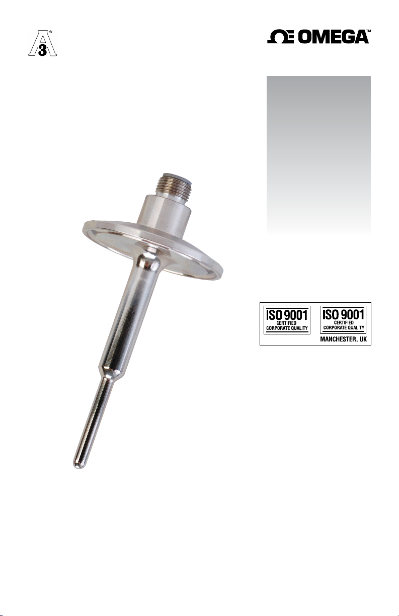
User’s Guide
NORWALK, CT
Shop online at
omega.com
e-mail: [email protected]
For latest product manuals:
www.omegamanual.info
M12 CONNECTOR STYLE
THS SERIES
Sanitary Thermistor Sen
sors
Page 2
M-4913-E Instruction Manual for M12 Connector Style THS Series
Sanitary Thermistor Sensors
The PRS series sensors are manufactured
with 316L stainless steel wetted surfaces that
have surface finishes of 32
Care should be exercised when handling the
sensors so that the surface finish is not
damaged during handling or installation.
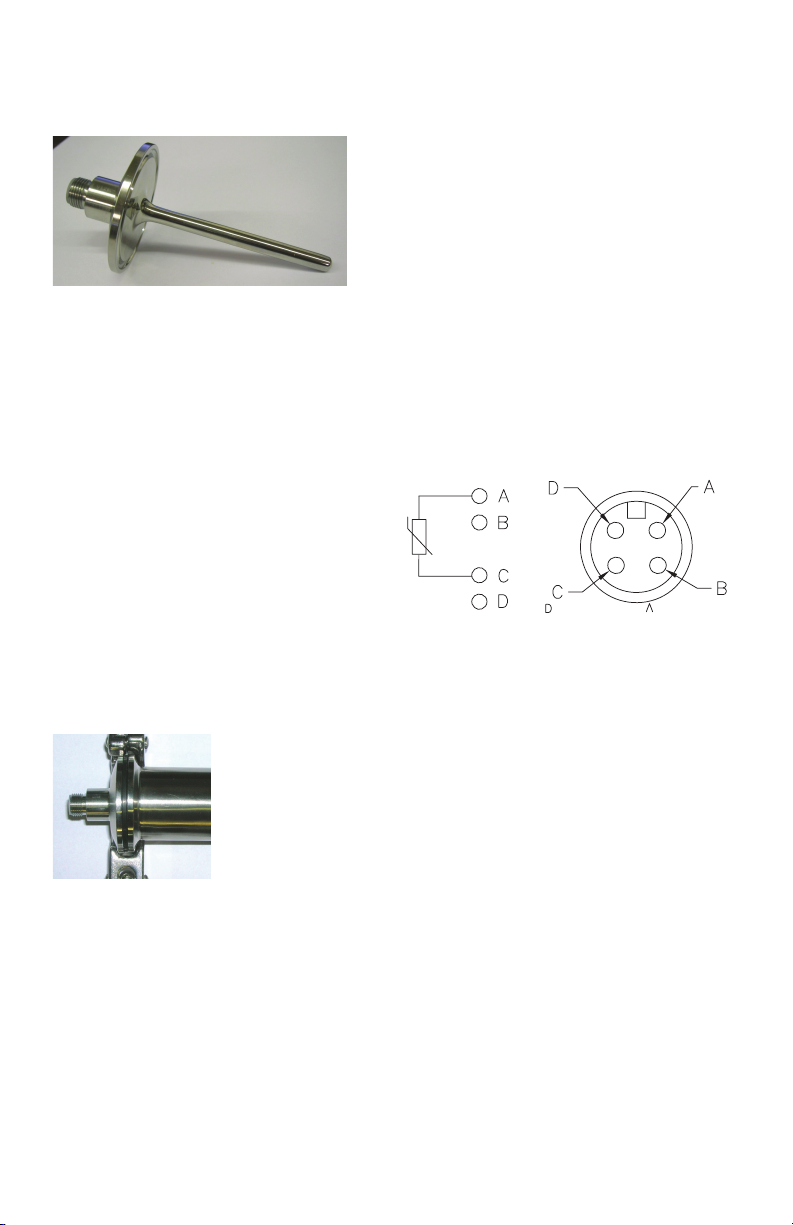
WIRING CONFIGURATION:
GENERAL DESCRIPTION
The Omega PRS series sensors are designed
for use in Sanitary Clean-In-Place (CIP)
systems. They are supplied standard with
1/2" 16AMP Style flanges so they can be
1-
assembled to like style piping connections.
Other connection sizes and styles are
available.
These sensors are supplied with thermistor
elements that provide a non-linear resistance
temperature output that has significantly
greater resolution (in ohms per degree) than
do our RTD sensors. Please note that
thermistor sensors require lower operating
currents than do RTD sensors, typically
around 12 microamps max, in order to
insure that no self-heating occurs.
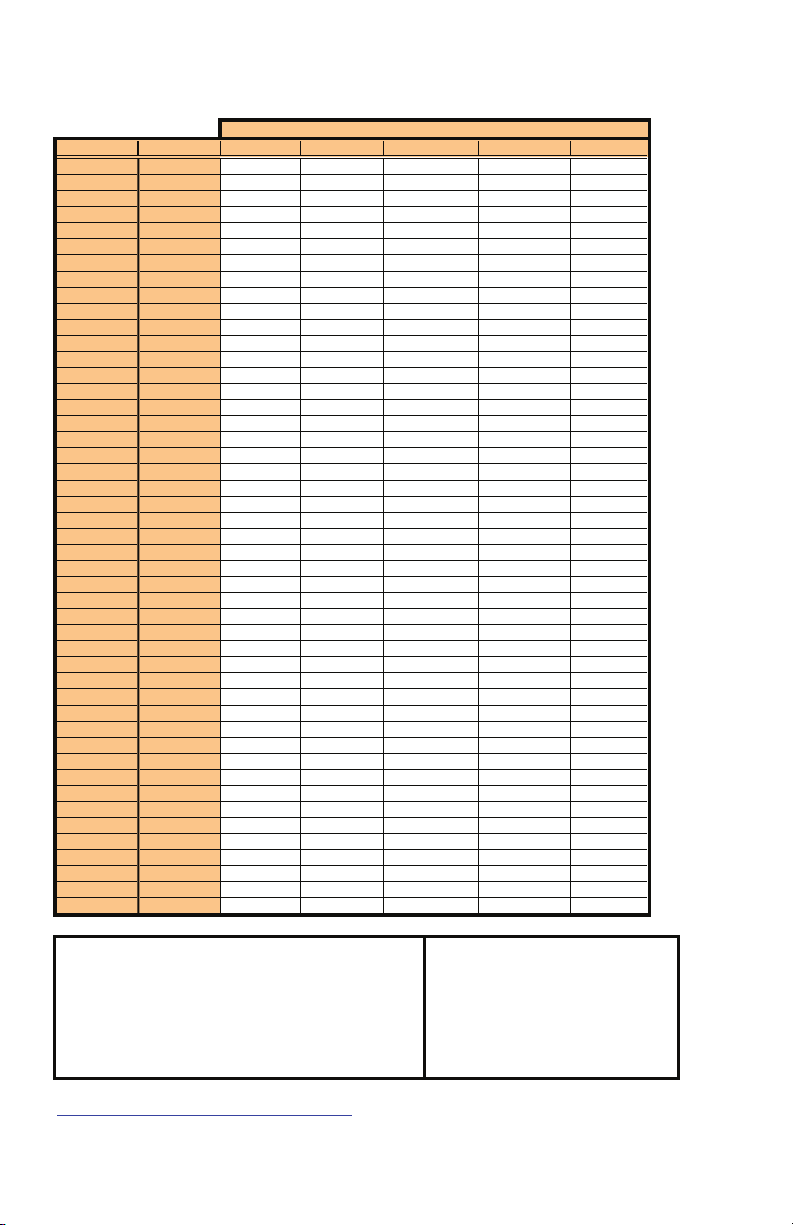
Resistance vs. Temperature Tables and
Equations for each thermistor offered are
provided on page 2.
The Omega THS Style sensors are supplied
with 4-pin, M12 connectors for convenient
connection to your process instrumentation
using a suitable extension cable. The wiring
arrangement of the connector pins is shown
in the detail below. Please note that
thermistor sensors are 2-wire devices and
have no polarity associated with their use.
OPERATING CURRENT:
As is the case with most precision thermistor
sensors, Omega THS series sensors should
be powered with no more than 12
microamps of excitation current. If operated
at higher currents, self heating errors may
occur.
microinch
or
better
PROCESS CONNECTION:
This sensor includes a mounting flange that
connects to a similar flange located at the
process connection point. A commercially
available gasket is used between the sensor
flange and the process flange, with a clamp
used to compress the two together.
SPECIFICATIONS:
Sensing Element Type: Thermistor
Accuracy: ±0.2°C between 0 and 70°C.
Temperature Range: -80 to 150°C (-112 to
302°F).
Excitation Current: 12 microamps max.
Response Time: 2.5 seconds max (63%)
Wetted Surfaces: 316L Stainless Steel with
32 microinch or better surface finish.
Process Connection: M12 4-Pin Connector.
Page 3
p
(
)
M-4913-E Instruction Manual for M12 Style Sanitary Thermistor Sensors
Resistance Vs. Temperature Table: Resistance Listed in Ohms
Temp (°F)
Temp(°C
) 2K 3K 5K 10K 30K
-112 -80 1662564 2220043 3686168 3581357 15739361
-103 -75 1073115 1432900 2378027 2449596 10508458
-94 -70 704145 940215 1559792 1697658 7114634
-85 -65 469308 626650 1039314 1191325 4881167
-76 -60 317460 423899 702918 845998 3391326
-67 -55 217788 290815 482182 607604 2384663
-58 -50 151423 202202 335243 441117 1696095
-49 -45 106630 142392 236082 323559 1219577
-40 -40 76003 101497 168287 239671 886113
-31 -35 54803 73187 121359 179206 650261
-22 -30 39954 53358 88488 135203 481743
-13 -25 29436 39312 65204 102883 360159
-4 -20 21906 29255 48531 78936 271616
5 -15 16459 21981 36470 61042 206557
14 -10 12480 16667 27658 47561 158343
23 -5 9546 12749 21160 37328 122318
32 0 7364 9834 16324 29500 95188
41 5 5726 7646 12695 23470 74601
50 10 4486 5991 9949 18793 58865
59 15 3541 4729 7854 15141 46753
68 20 2815 3759 6244 12271 37367
77 25 2253 3008 4998 10002 30046
86 30 1815 2423 4026 8198 24301
95 35 1471 1964 3264 6754 19765
104 40 1199.5 1601 2661 5593 16162
113 45 983.8 1313 2183 4655 13285
122 50 811.2 1082.5 1800 3892 10975
131 55 672.6 897.3 1492 3270 9111
140 60 560.4 747.6 1243 2758 7599
149 65 469.3 625.9 1041.1 2337 6366
158 70 394.8 526.5 875.8 1988 5357
167 75 333.7 444.9 740.2 1698 4526
176
80 283.
3 377.6 628.3 1456 3840
185 85 241.5 321.9 535.5 1253 3271
194 90 206.7 275.5 458.3 1082.4 2797
203 95 177.6 236.7 393.8 938.1 2400
212 100 153.2 204.1 339.6 815.8 2067
221 105 132.6 176.7 293.9 711.7 1786
230 110 115.2 153.4 255.3 622.8 1548
239 115 100.4 133.7 222.5 546.7 1347
248 120 87.8 116.9 194.6 481.3 1175
257 125 77.1 102.6 170.7 424.9 1029
266 130 67.8 90.3 150.2 376.2 902.8
275 135 59.9 79.7 132.5 333.9 794.7
284 140 53.0 70.5 117.3 297.2 701.4
293 145 47.0 62.6 104.1 265.2 620.8
302 150 41.9 55.7 92.6 237.2 550.8
Equations:
where t = temperature in °C
Constants:
Code R A B C Constants:
2K 2252 1.468x10⁻³ 2.383x10⁻⁴ 1.007x10⁻⁷ alpha = ((A-(1/T))/C)
3K 3000 1.403x10⁻³ 2.373x10⁻⁴ 9.827x10⁻⁸ beta = SQRT(((B/3C))3)+(alpha2/4))
5K 5000 1.285x10⁻³ 2.362x10⁻⁴ 9.285x10⁻⁸ T = Tem
10K 10000 1.032x10⁻³ 2.387x10⁻⁴ 1.580x10⁻⁷
30K 30000 9.376x10⁻⁴ 2.208x10⁻⁴ 1.276x10⁻⁷
For Resistance Vs. Temperature Tables in 1°C Increments, go to our website at
http://www.omega.com/temperature/Z/pdf/z256-257.pdf
Sensor Code
erature in Kelvins
°C+273.15
:erutarepmeT morf ecnatsiseR gnitaluclaC:ecnatsiseR morf erutarepmeT gnitaluclaC
3/1))2/ahpla(+ateb((-3/1))2/ahpla(-ateb(e=R 3])R(nL[C+ ])R(nL[B+A=t/1
Page 4

omega.com [email protected]
Servicing North America:
U.S.A. Omega Engineering, Inc.
Headquarters: Toll-Free: 1-800-826-6342 (USA & Canada only)
Customer Service: 1-800-622-2378 (USA & Canada only)
Engineering Service: 1-800-872-9436 (USA & Canada only)
Tel: (203) 359-1660 Fax: (203) 359-7700
e-mail: [email protected]
For Other Locations Visit omega.com/worldwide
The information contained in this document is believed to be correct, but OMEGA accepts no liability for any errors it
contains, and reserves the right to alter specifications without notice.
DISCLAIMER
If the unit malfunctions, it must be returned to the factory for evaluation. OMEGA’s Customer Service Department
will issue an Authorized Return (AR) number immediately upon phone or written request. Upon examination by
OMEGA, if the unit is found to be defective, it will be repaired or replaced at no charge. OMEGA’s WARRANTY does
not apply to defects resulting from any action of the purchaser, including but not limited to mishandling, improper
interfacing, operation outside of design limits, improper repair, or unauthorized modification. This WARRANTY is
VOID if the unit s
result of excessive corrosion; or current, heat, moisture or vibration; improper specification; misapplication;
misuse or other operating conditions outside of OMEGA’s control. Components in which wear is not warranted,
include but are not limited to contact points, fuses, and triacs.
OMEGA is pleased to offer suggestions on the use of its various products. However, OMEGA
neither assumes responsibility for any omissions or errors nor assumes liability for any damages that
result from the use of its products in accordance with information provided by OMEGA, either
verbal or written. OMEGA warrants only that the parts manufactured by the company will be as
specified and free of defects. OMEGA MAKES NO OTHER WARRANTIES OR REPRESENTATIONS OF
ANY KIND WHATSOEVER, EXPRESSED OR IMPLIED, EXCEPT THAT OF TITLE, AND ALL IMPLIED
WARRANTIES INCLUDING ANY WARRANTY OF MERCHANTABILITY AND FITNESS FOR A
PARTICULAR PURPOSE ARE HEREBY DISCLAIMED. LIMITATION OF LIABILITY: The remedies of
purchaser set forth herein are exclusive, and the total liability of OMEGA with respect to this order,
whether based on contract, warranty, negligence, indemnification, strict liability or otherwise, shall not
exceed the purchase price of the component upon which liability is based. In no event shall OMEGA be
liable for consequential, incidental or special damages.
CONDITIONS: Equipment sold by OMEGA is not intended to be used, nor shall it be used: (1) as a “Basic
Component” under 10 CFR 21 (NRC), used in or with any nuclear installation or activity; or (2) in medical
applications or used on humans. Should any Product(s) be used in or with any nuclear installation or activity,
medical application, used on humans, or misused in any way, OMEGA assumes no responsibility as set forth in our
basic WARRANTY / DISCLAIMER language, and, additionally, purchaser will indemnify OMEGA and hold OMEGA
harmless from any liability or damage whatsoever arising out of the use of the Product(s) in such a manner.
Direct all warranty and repair requests/inquiries to the OMEGA Customer Service Department. BEFORE RETURNING
ANY PRODUCT(S) TO OMEGA, PURCHASER MUST OBTAIN AN AUTHORIZED RETURN (AR) NUMBER FROM
OMEGA’S CUSTOMER SERVICE DEPARTMENT (IN ORDER TO AVOID PROCESSING DELAYS). The assigned AR
number should then be marked on the outside of the return package and on any correspondence.
The purchaser is responsible for shipping charges, freight, insurance and proper packaging to prevent breakage
in transit.
FOR WARRANTY RETURNS, please have the following
information available BEFORE contacting OMEGA:
1. Purchase Order number under which the product was
PURCHASED,
2. Model and serial number of the product under warranty,
and
3. Repair instructions and/or specific problems relative to the
product.
OMEGA’s policy is to make running changes, not model changes, whenever an improvement is possible. This affords our
customers the latest in technology and engineering. OMEGA is a trademark of OMEGA ENGINEERING, INC.
© Copyright 2018 OMEGA ENGINEERING, INC. All rights reserved. This document may not be copied, photocopied, reproduced,
translated, or reduced to any electronic medium or machine-readable form, in whole or in part, without the prior written consent of
OMEGA ENGINEERING, INC.
hows evidence of having been tampered with or shows evidence of having been damaged as a
RETURN REQUESTS / INQUIRIES
FOR NON-WARRANTY REPAIRS,
repair charges. Have the following information available
BEFORE contacting OMEGA:
1. Purchase Order number to cover the COST of the repair,
2. Model and serial number of the product, and
3. Repair instructions and/or specific problems relative to the
product.
consult OMEGA for current
M4913-E/0418
 Loading...