

Page 1
1
Page 2

2
Page 3

SPECIFICATION StepOne
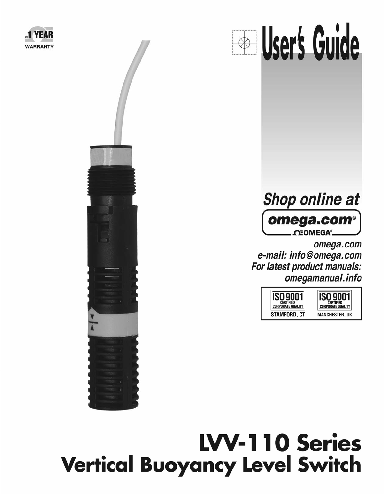
AboutVerticalBuoyancyLevelSwitchSensors:TheVerticalBuoyancyLevelSwitchconsistsofafloat,magnet
reedswitchandbafflebody whichdampensturbulence andeliminatesthe negativeeffectsof switchchatter.
When the probe is dry, the float rests on the bottom of the baffle body such that the magnet does not
influence the reed switch. As the probe becomes immersed in liquid, the float becomes buoyant and the
magnetelevatescausingthereedswitchtochangetochange.
TableofContents
Specifications:.........................................................................................................................................................4
Dimensions:.............................................................................................................................................................4
SafetyPrecautions:.................................................................................................................................................5
Installation:............................................................................................................................................................6
TopWallInstallation:.................................................................................................................................6
BayonetConnection:..................................................................................................................................6
Orientation:................................................................................................................................................6
ConnectiontoaSwitchCarKit(LVM‐20series)::......................................................................................7
Electrical:................................................................................................................................................................8
LVM‐10seriesandLVM‐50seriesAssemblies:.........................................................................................8
Wiring:....................................................................................................................................................................9
WiringtoanOmegaEngineeringController:.............................................................................................9
Maintenance:.......................................................................................................................................................10
3
Page 4
SPECIFICATION/DIMENSION StepTwo
Accuracy: ±2mminwater
Repeatability: ±1mminwater
Orientation: ±20˚fromvertical
SpecificGravity: 0.8minimum
ContactType: (1)SPDTreed
ContactRating: 15VA,0.25Amax.
ContactVoltage: 120VAC,120VDC@15VA
ContactOutput: SelectableNO/NC
TemperatureRange: F:‐40˚to176˚
C:‐40˚to80˚
PressureRange: 25psi(2bar)@25˚C.,derated
@ 1.667 psi (.113 bar) per ˚C.
above25˚C.
SensorRating: NEMA6/IP68
SensorMaterial: Polypropylene(PP)
PolyvinylideneFluoride(PVDF)
CableType: 3‐cond.r,22‐gauge,shielded
CableLength: 10’(3m)
CableMaterial: PPorPFAjacket
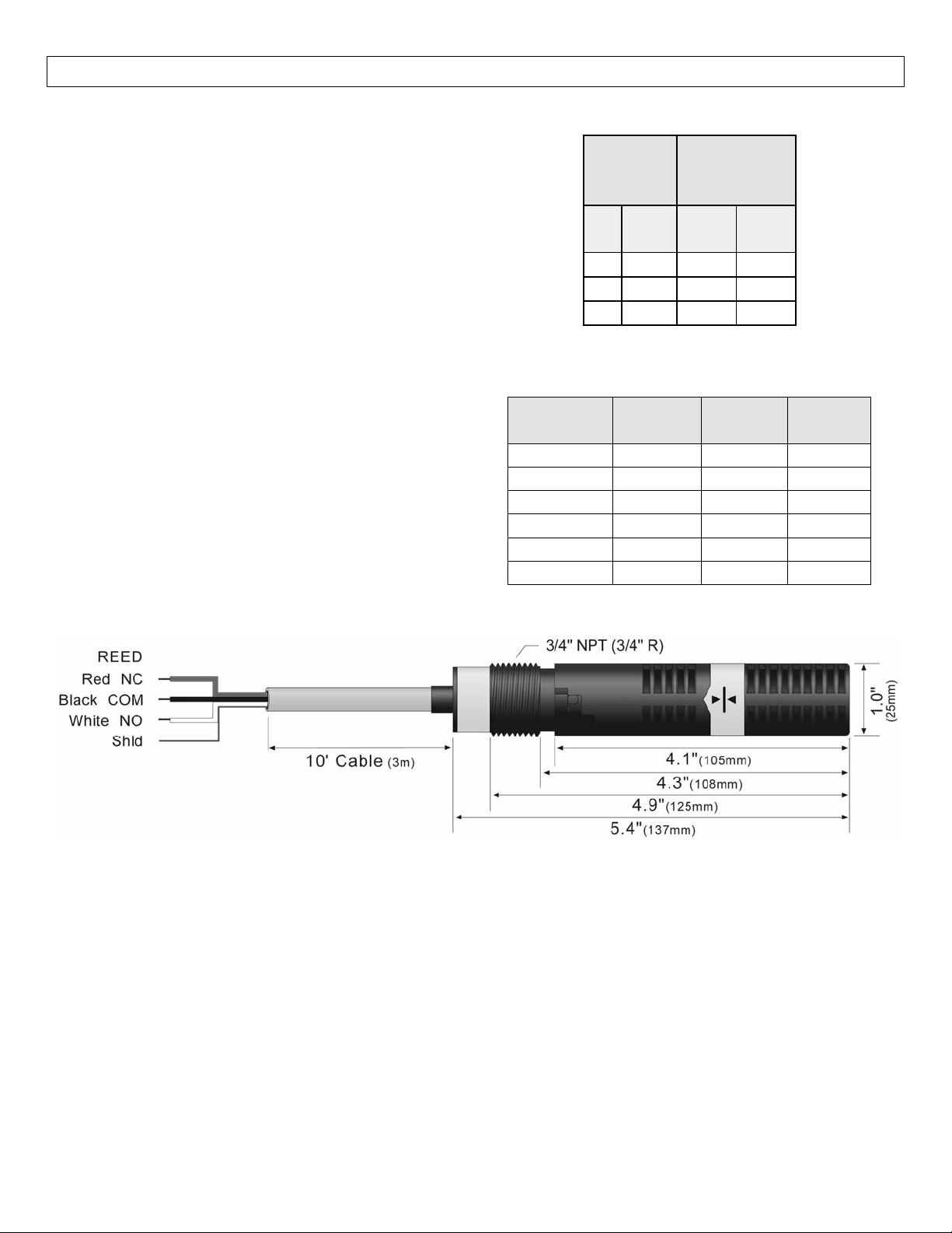
MountingThreads: 3/4”NPT
SwitchRating:
Reed
Switch
Rating
VA Volts Amps
Maximum
Resistive
Load
Amps
AC
DC
15 0‐50 0.3 0.21
15 120 0.13 0.09
15 240 0.06 0.04
Components:
Part
Number
Body
Material
Cable
Material
LVV‐110 PP PP 10’
LVV‐110‐25 PP PP 25’
LVV‐110‐50 PP PP 50’
LVV‐111 PVDF PFA 10’
LVV‐110‐25 PVDF PFA 25’
LVV‐110‐50 PVDF PFA 50’
Cable
Length
Dimensions:
4
Page 5

SEFETYPRECAUTION StepThree
About Manual: PLEASEREAD THEENTIRE MANUALPRIOR TO INSTALLINGOR USING THISPRODUCT.This
manual includes information on the vertical buoyancy, Model LVV‐110 & LVV‐111. Please refer to the part
numberlocatedonthesensorlabeltoverifytheexactmodelwhichyouhavepurchased.
User’sResponsibility for Safety:OMEGAENGINEERINGmanufacturesa wide rangeofliquidlevelswitches
andtechnologies.Whileeachof thetheseswitchesaredesignedto operateinawidevarietyof applications,
itistheuser’sresponsibilitytoselectaswitchmodelthatisappropriatefortheapplication,installitproperly,
perform tests of the installed system, and maintain all components. The failure to do so could result in
propertydamageorseriousinjury.
ProperInstallationandHandling:Becausethisisanelectricallyoperateddevice,onlyproperlytrainedstaff
should installand/or repair this product. Use a proper sealant withall installations.Never over tighten the
sensorwithinthefitting,beyondamaximumof80inch‐poundstorque.Alwayscheckforleakspriortosystem
start‐up.
Material Compatibility: The LVV‐110 series level switch is available in two wetted material versions.The
switch and the cable are made of Polypropylene (PP) for the LVV‐110 models.The switch is made of
PolyvinylideneFluoride(PVDF)andcableismadeofPerfluoroalkoxy(PFA)fortheLVV‐111models.Makesure
thattheswitch is compatible with theapplication liquids.To determine thechemicalcompatibility between
thesensoranditsapplicationliquids,refertotheCompassCorrosionGuide.
TemperatureandPressure:TheLVV‐110Seriesswitchisdesignedforuseinapplicationtemperaturesupto
80˚C,andforuseatpressuresupto25psi(2bar)@25˚C.,derated@1.667psi(.113bar)per˚C.above25˚C.
WiringandElectrical:The supplyvoltageusedfortheLVV‐110 seriesshouldnever exceed120voltsAC@
15 VA.Electrical wiring of the switch should be performed in accordance with all applicable national, state,
andlocalcodes.
Flammable, Explosive and Hazardous Applications: The LVV‐110 Series switch should not be used within
flammable or explosive applications unless properly connected to an approved control device. In hazardous
applications, use redundant measurement and control points, each having a different sensing technology.
RefertotheNationalElectricalCode(NEC)forallapplicableinstallationrequirementsinhazardouslocations.
Warning
AvoidinstallingtheLVV‐110 seriesintanks inmagnetizedmetal tanks.Doingsowillactivatetheinternal reed
switch.
5
Page 6
INSTALLATION StepFour
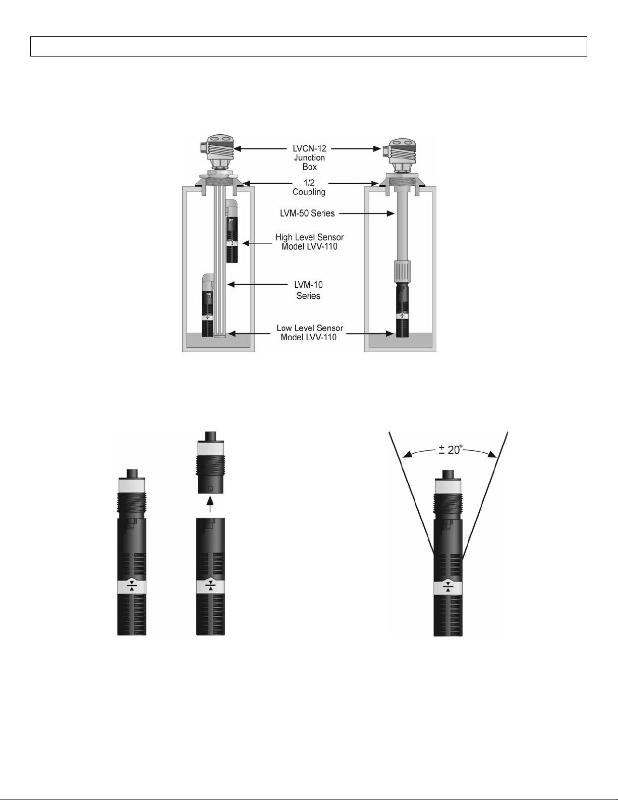
TopWallInstallation:OMEGAENGINEERING’sLVV‐110seriesmaybeinstalledthroughthetopwallofatank.
For Level Track Mounting System (LVM‐10 series) installations, remove the sensors thread and use the
bayonetadaptertointerfacetotheLVM‐20seriesSwitchCar.FortheSingle‐SwitchFittingAssembly(LVM‐50
series)installationsusethe3/4”threadastheinterface.
BayonetConnection:The¾”threadcanberemoved
toaccessthebayonetconnection.Simplepressdown
onthethreadsandtwisttorelease.
Orientation: Mounting orientation bust be kept
vertical for proper orientation. The vertical buoyancy
and float switches are orientated in vertical position
±20˚.
6
Page 7
INSTALLATION(continued) StepFour
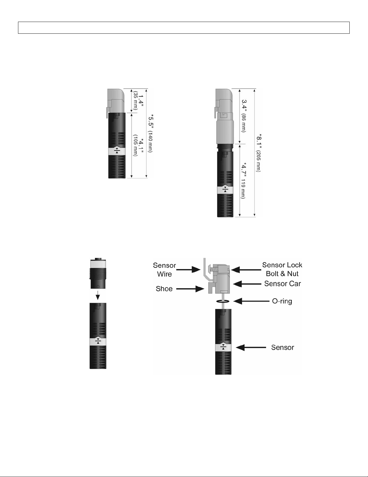
ConnectiontoaSwitchCarKit(LM30series):InordertoattachtheLVV‐110SeriestoaLevelTrackMounting
System (LVM‐10 series) fitting, a Switch Car Kit (LVM‐20 series) is required.The LVV‐110 Series can be
attachedintwoways,withoutthebayonetadapterandwiththebayonetadapter.
WithoutBayonetAdapter WithBayonetAdapter
Theuseofthebayonet adapter willincreasetheoveralllengthof the LVV‐110/LVM‐20 series assembly.This
willresult in aloweractivationpointwithinthe tank duetotheadded length.It is recommendedtoremove
thebayonetadapterwheninterfacingwithLevelTrackMountingSystem.
First, remove the bayonet
adapter by pressing down
twistingtheadapter.
Next,threadthesensor wirethroughtheO‐ringand the
sensorcarandoutthroughtheholebetweenthesensor
car shoe and the locking bolt.Set the O‐ring into the
LVV‐110.Push the sensor into the bayonet side of
sensorcar.Screwthebayonet adapter onto the sensor
untilthesensorseatsagainstthepitinsidetheadapter.
7
Page 8
ELECTRICAL StepSix
Voltage:Theinputvoltage to the LVV‐110 series should neverexceedthemaximumvoltage rating.OMEGA
ENGINEERING controllers have a built‐in 13.5 VDC power supply which provides power to all of OMEGA
ENGINEERING’s level switches. Alternate controllers and power supplies may also be used with the LVV‐110
series.
Cable Length:Determine the length of cable required between the LVV‐110 Series sensor and its point of
termination. Allow enough slack to ensure the easy installation, removal and/or maintenance of the sensor.
Thecablelengthmaybeextendeduptoamaximumof1000feet,usingawellinsulated,shieldedwire.
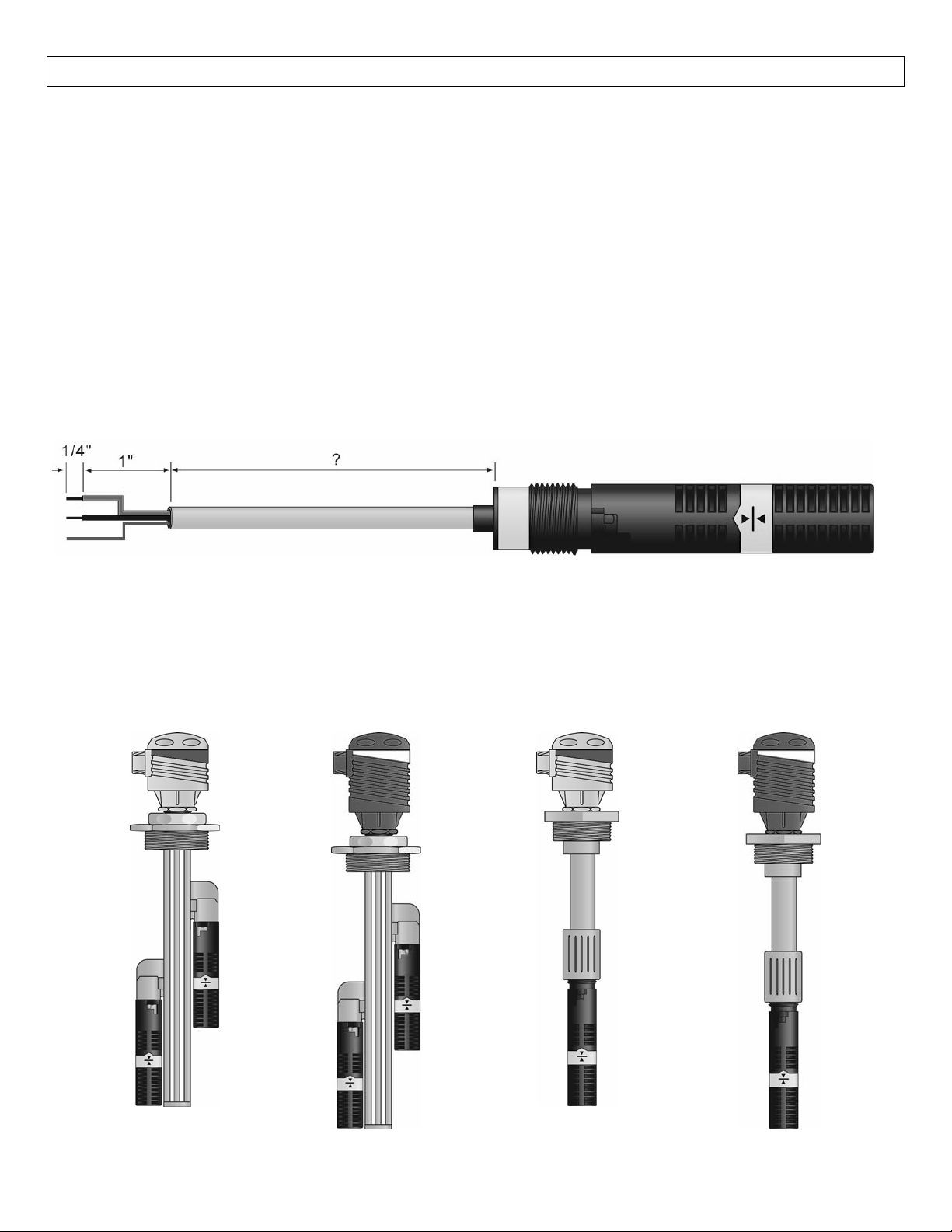
WireStripping:Usinga10gaugewirestripper,carefullyremovetheouterlayerofinsulationfromthelast1‐
1/4” of the sensor’s cable. Unwrapand discard the exposed foil shield from around the signal wires,leaving
thedrainwireattachedifdesired.Witha20gaugewire
striper,removethelast1/4"ofthecoloredinsulation
fromthesignalwires.
LevelTrackMountingSystemandSingle‐SwitchFittingAssembly:TheLVV‐110seriescanbepackagedwith
OmegaEngineeringLevelTrackMountingSystemandSingle‐SwitchFittingAssembly.
LevelTrackMounting
SystemwithJunction
Boxand(2)Switches
LevelTrackMounting
SystemwithRelay
Controllerand(2)
Switches
Single‐SwitchFitting
AssemblywithJunction
Boxand(1)Switch
Single‐SwitchFitting
AssemblywithRelay
Controllerand(1)
Switch
8
Page 9
WIRING StepSeven
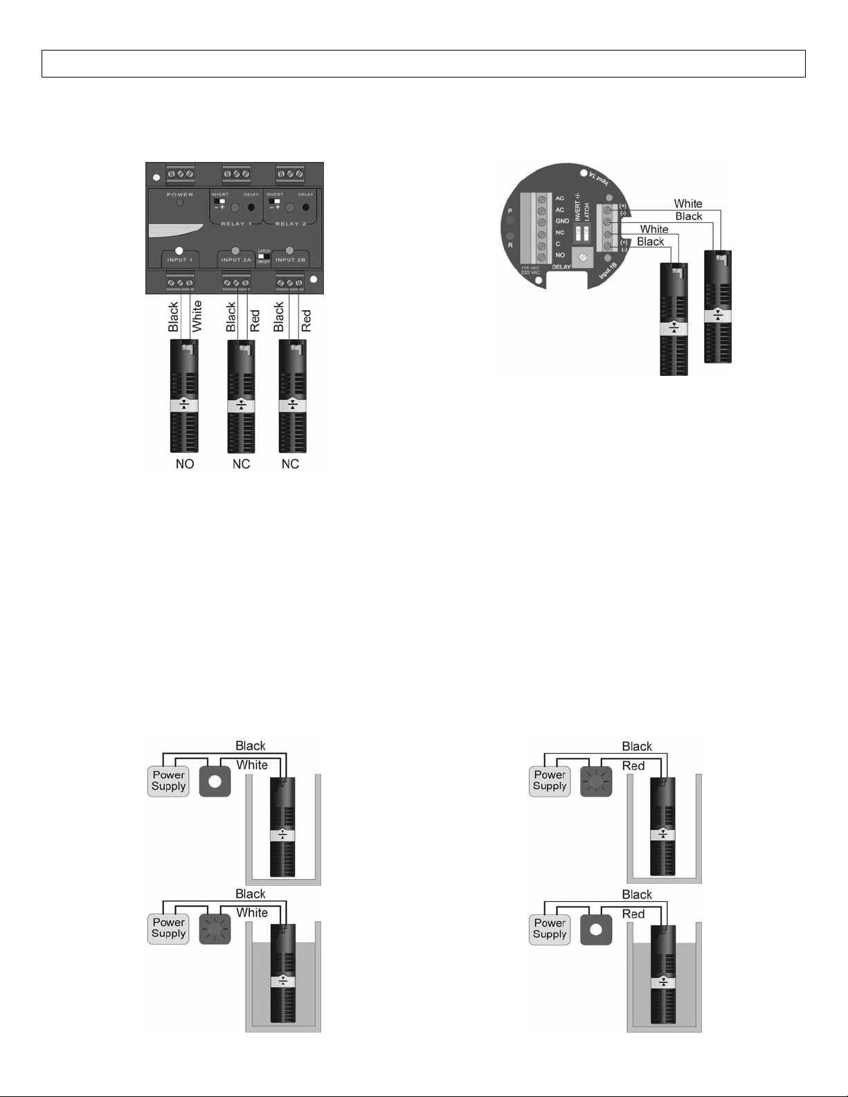
WiringtoaOMEGAENGINEERINGController
LVCN‐120SeriesController(LVCN‐120Shown):
LVCN‐100SeriesController(LVCN‐20shown):
NOTE:When usingalatchingrelay,thepolarityof bothswitchesmustbethe same.Eitherbothswitchesare
wiredNormallyClosed(Red & Black – See Relay #2withLVCN‐120)or both Normally Open (White & Black –
SeeRelay#1withLVCN‐20).
VerticalBuoyancyLevelSwitch:
TheLVV‐110seriescanbewirednormallyopenornormallyclosedforyourapplicationrequires.
Normally Open:Use the Black and White wire for
operation the LVV‐110 series in a normally open
state. Normally open is defined as the switch being
openwhenthefloatisdry and closed when the float
becomes submersed. This operation is typical for
indicatingahighlevel.
Normally Closed:Use the Black and Red wires for
operatingtheV‐110series in a normallyclosedstate.
Normallyclosedisdefinedastheswitch being closed
when the float is dry and open when the float
becomes submersed. This operation is typical for
indicatingalowlevel.
9
Page 10
MAINTENANCE StepEight
General: While a filter shroud protects the float from particulate contamination, the switch may need to be
cleanedperiodicallytoprevent jammingofsticking.Theverticalbuoyancyand verticalfloathas noscheduled
maintenance requirement, except to clean off any deposits or scaling from the switch asnecessary. It is the
responsibility of the user to determine the appropriate maintenance schedule, based on the specific
characteristicsoftheapplicationliquid.
Cleaningprocedure:
1. Power: Make sure that all power to the switch, controller and/or power supply is completely
disconnected.
2. Switch removal: If necessary, make sure that the tank is drained well below the switch prior to
removal. Carefully, remove the sensor from the installation. Remove the outer screen by pushing on
thescreenand turning it slightly todisconnectitfromthebuoyancy net connector so thatthefloatis
exposed.
3. Cleaning the switch: using a soft bristle brush and mild detergent, carefully wash the switch. Do not
use harsh abrasives such assteel wool or sandpaper, which might damage the surface of the sensor.
Do not use incompatible solvents which may damage the sensor’s PP or PVDF plastic body. Take
particularcaretoremoveanyscalingfromthefloatbodyandmakesurethatitmovesfreely.
4. Sensorinstallation:FollowtheappropriatestepsofinstallationasoutlinedintheInstallationsectionof
thismanual.
Testingtheinstallation:
1. Power:Turnonpowertothecontrollerand/orpowersupply.
2. Immersing the switch: Immerse the sensing tip in its application liquid, by filling the tank up to the
switchduringpreliminarytestingistoholdacupfilledapplicationliquiduptotheswitch’stip.
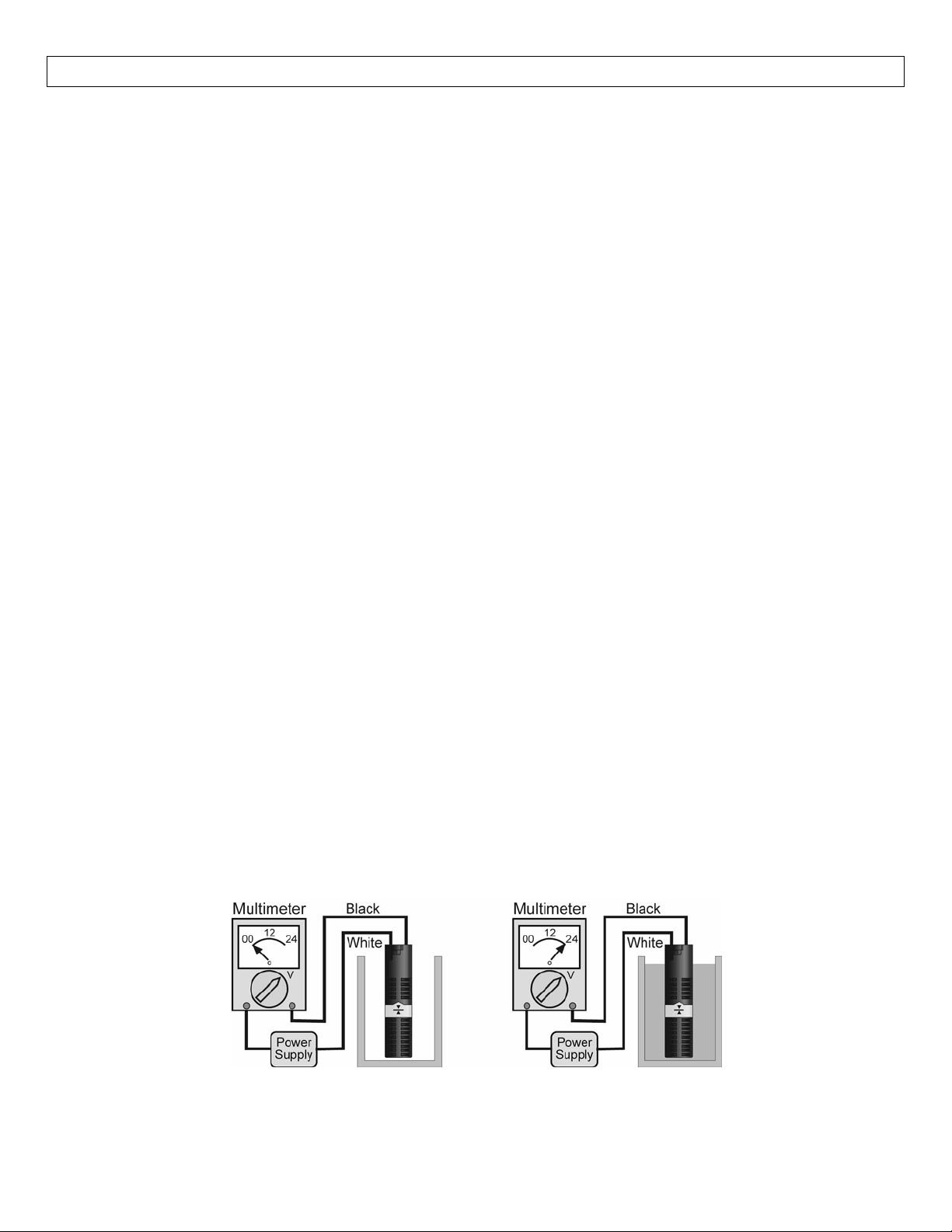
3. Test: With the switch being fluctuated between wet and dry states, the switch indicator light in the
controllershouldturnonandoff.Ifthecontrollerdoesn’thaveaninputindicator,
a. Useavoltmeterwithapowersupplyinseriestomeasureanopenorclosedcircuit.
b. Useanohmmeterinseriestomeasureanopenorclosedcircuit.
4. Point of actuation: Observe the point at which the rising or falling
fluid level causes the switch to
changestate,andadjusttheinstallationoftheswitchifnecessary.
Example:TestingtheLVV‐110SerieswithaMultimetersettoreadVolts.WhenwiredNO(BlackandWhite),
themeterwillread0voltswhendryandfullvoltagewhenwet.
10
Page 11

11
Page 12

12
 Loading...