

Page 1
12
Page 2
Page 3

INTRODUCTION/TABLEOFCONTENTS StepOne
An ultrasonic sound wave is pulse eight times per second from the base of the transducer. The sound wave
reflects against the process medium below and returns to the transducer. The microprocessor based
electronics measure the time of flight between the sound generation and receipt, and translates this figure
intothedistancebetweenthetransducerandprocessmediumbelow.
TableofContents
Specifications......................................................................................................................................................................4
Dimensions.................................................................................................................................................................4
Components...............................................................................................................................................................5
Sinkingvs.Sourcing....................................................................................................................................................5
SafetyPrecautions..................................................................................................................................................................6
Menu/Definitions..................................................................................................................................................................7
Configuration......................................................................................................................................................................9
StepsforBasicConfiguration....................................................................................................................................9
SelectingUnitsofOperation.....................................................................................................................................9
ConfigureSensor’sCurrentRange............................................................................................................................9
ConfigureSe
Wiring ....................................................................................................................................................................11
Installation....................................................................................................................................................................12
MountingGuide.......................................................................................................................................................12
FittingSelection.......................................................................................................................................................13
TankAdapter...............................................................................................................................................13
Riser............................................................................................................................................................13
Flange..........................................................................................................................................................13
SideMountFitting......................................................................................................................................14
StandPipe...................................................................................................................................................14
RelayExamples....................................................................................................................................................................15
Ex:HighAlar
Ex:AutomaticFill.....................................................................................................................................................15
Maintenance/AdvancedFeatures.......................................................................................................................................16
FactorySettingsandReset.......................................................................................................................................16
ChangingDisplayunits.............................................................................................................................................16
Testingthetransmitter............................................................................................................................................16
Troubleshooting....................................................................................................................................................................17
SolutionTable..........................................................................................................................................................17
OtherHints...............................................................................................................................................................18
nsor’sRelay...............................................................................................................................
m...............................................................................................................................
...........................15
..........10
3
Page 4
SPECIFICATIONS StepTwo
Range: 0.5to24.5feet
(15cmto7.4m)
Accuracy: ±0.25%ofrange(air)
Resolution: 0.125”(3mm)
Frequency: 50kHz
PulseRate: 8pulsespersecond
DeadBand: 6”(15cm)
Beamwidth: 8°conical
Configuration: Pushbutton
Memory: Non‐volatile
DisplayType: 4segmentLED
Displayunits: Inchorcm
LEDIndication: Relaystatus
SupplyVoltage: 14‐36VDC
Consumption: 200mA
Signaloutput: 4‐20mA,three‐wire
Signalinvert: 4‐20mA/20‐4mA
Currentflow: Sourcingorsinking
Contacttype: (1)SPDTrelay,latching
Contactrating: 250VAC,10A
Contactlogic: Singlepoint:alarm
Twopoint:latching
Contactfail‐safe: Revertstosafestateduring
echoloss
ProcessTemp.: F:‐4°to140°
C:‐20°to60°
Temp.Compensation: Automatic
Ambienttemp.: F:‐40°to140°
C:‐40°to60°
Pressure: 30psi(2bar)@25°C.,
derated@1.667psi(.113
bar)per°C.above25°C.
Enclosurerating: NEMA4X(IP65)
Enclosurematerial: Polypropylene,U.L.94VO
Conduitentrance: Single,1/2"NPT
Cablelength: 9”(22cm)
Cabletype: Power/signal:3‐conductor
Relay:3‐conductor
Cablejacketmat’l: Vinyl
Transducermaterial: PolyvinylideneFluoride
(PVDF)
Processmount: 2”NPT
Classification: GeneralPurpose
Compliance: CE
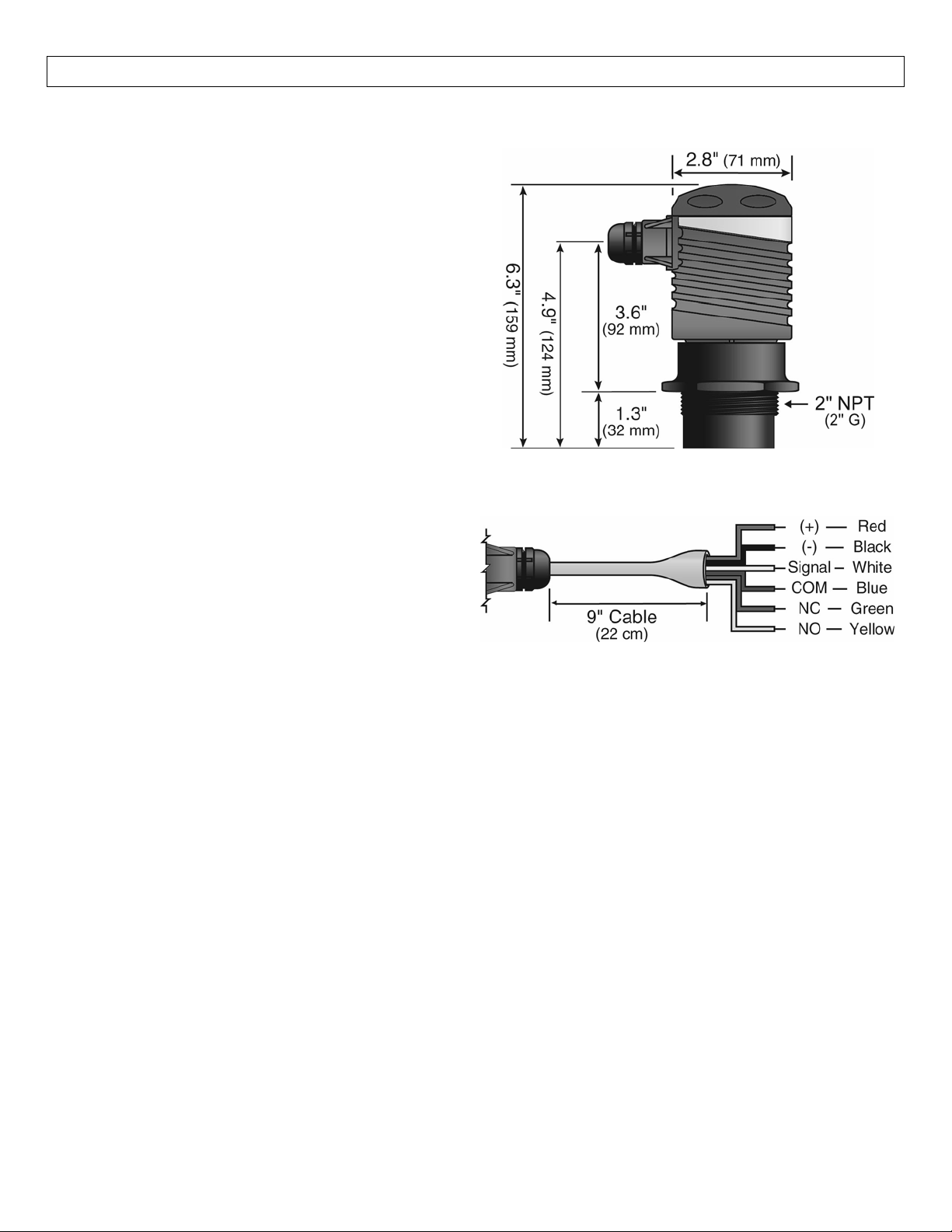
LVU‐301/‐303Series
SideView
LVU‐301/‐303Series
CableView
4
Page 5
SPECIFICATIONS StepTwo
Components:LVU‐301/‐303Seriesisofferedindifferentmodels.Dependingonthemodelpurchased,youmayormay
nothavebeenshippedallthecomponentsshownbelow.
P/N Max.Range DeadBand Thread CurrentOutput Relay
LVU‐303 24.5’(7.47m) 6”(15.2cm) 2”NPT Sourcing (1)
LVU‐301 24.5’(7.47m) 6”(15.2cm) 2”NPT Sinking (1)
QuickStartGuide
Sinkingvs.Sourcing:TheLVU‐301/‐303Seriesismanufacturedintwodifferentoutputs,sourcingandsinking.
A sourcing transmitter uses the negativeof the power supply as the reference for the entire system. When
using a sourcing unit, make sure that the negative of the ground is the common for the entire system. A
sinkingtransmitterusesthepositiveofthepowersupplyasthereferencefortheentiresystem.Whenusinga
sinkingunit,makesurethepositiveofthegroundisthecommonfortheentiresystem.
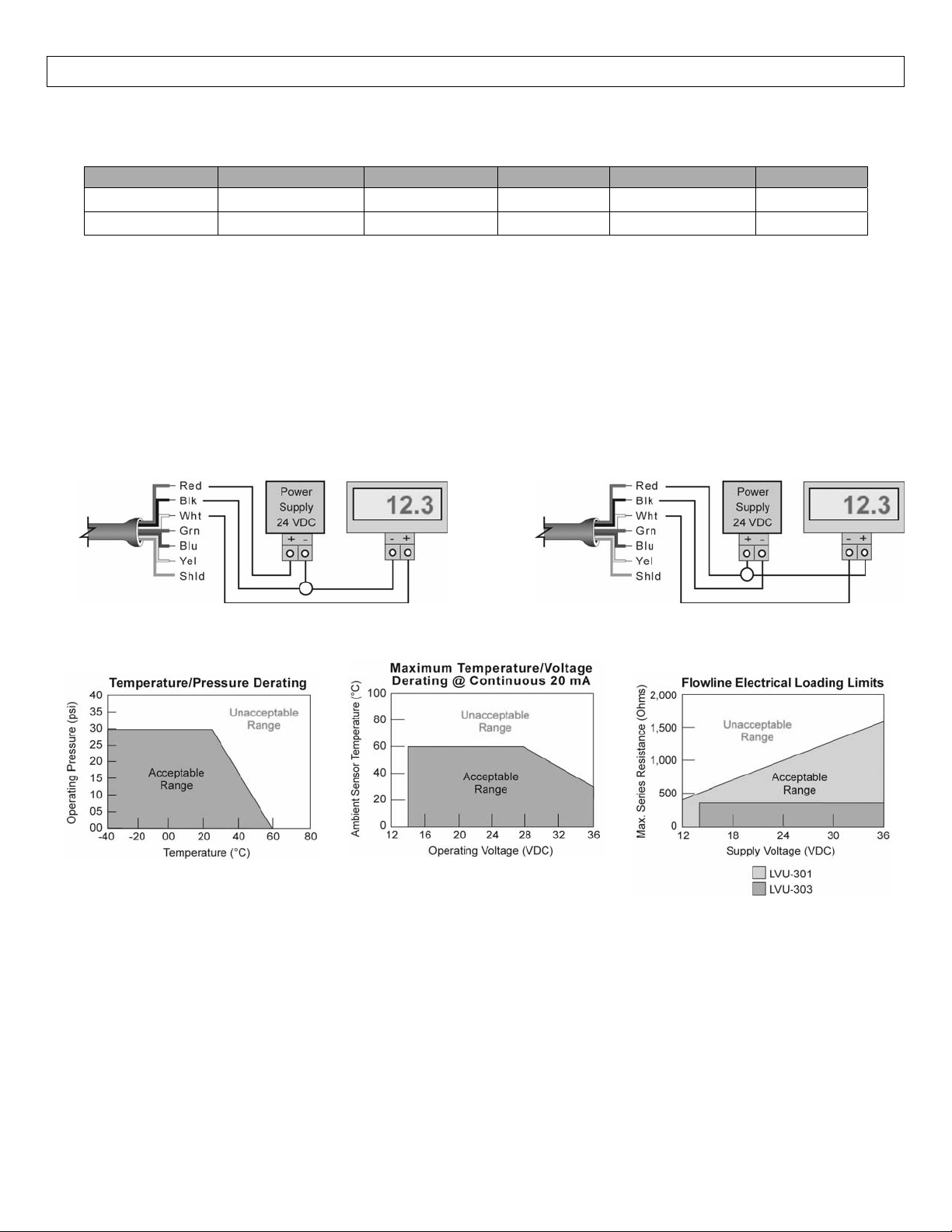
Sourcing(LVU‐303) Sinking(LVU‐301)
5
Page 6

SAFETYPRECAUTIONSStepThree
Aboutthis Manual:PLEASEREAD THEENTIREMANUALPRIORTO INSTALLINGORUSING THISPRODUCT.
This manual includes information on the continuous ultrasonic level transmitter from OMEGA
ENGINEERING;modelLVU‐301orLVU‐303.Pleaserefertothepartnumberlocatedonthesensorlabelto
verifytheexactmodelwhichyouhavepurchased.
User’sResponsibilityforSafety:OMEGAENGINEERING manufacturesawiderangeof liquidlevelsensors
and technologies.While each of these technologies are designed to operate in a wide variety of
applications, it is the user’s responsibility to select a technology that is appropriate for the application,
installitproperly,performtestoftheinstalledsystem, andmaintainallcomponents.Thefailuretodoso
couldresultinpropertydamageorseriousinjury.
Proper Installation and Handling:Because this is an electrically operated device, only properly trained
staff should install and/or repair this product.Use a proper sealant with all installations.Never over
tightenthetransmitterwithinthefitting.Alwayscheckforleakspriortosystemstart‐up.
Wiring and Electrical:A supply voltage of 14‐36 VDC (200 mA minimum supply) is used to power the
ultrasonictransmitter.Thesensorsystemshouldneverexceedamaximumof36VDC.Electricalwiringof
thesensorshouldbeperformedinaccordancewithallapplicablenational,state,andlocalcodes.
TemperatureandPressure:TheLVU‐301/‐303seriesisdesignedforuseinapplicationtemperaturesfrom
‐20°C (‐4°F)to 60°C (140°F),andforuse atpressures upto30psi(2bar)@ 25°C,derated@1.667psi
(0113bar)per°Cabove25°C.
Material Compatibility:The continuous ultrasonic level transmitter is made of two materials.The
enclosure is a Polypropylene (PP) and the transducer is made of Polyvinylidene Fluoride (PVDF).Make
surethat themodelwhichyouhave selectedis chemically compatiblewiththeapplicationliquids.While
the transmitter housing is liquid resistant when installed properly, it is not designed to be immersed.It
shouldnotbemountedinsuchawaythatitdoesnotnormallycomeintocontactwithfluid.
Flammable, Explosive and Hazardous Applications: The LVU‐301/‐303 series level transmitter system
shouldnotbenormallywithinflammableorexplosiveapplication.
MakeaFail‐SafeSystem:Design a Fail‐Safe system that accommodates the possibility of transmitter or
power failure.In critical application OMEGA ENGINEERING recommends the use of redundant backup
systemsandalarmsinadditiontotheprimarysystem.
6
Page 7
MENU/DEFINITIONS StepFour
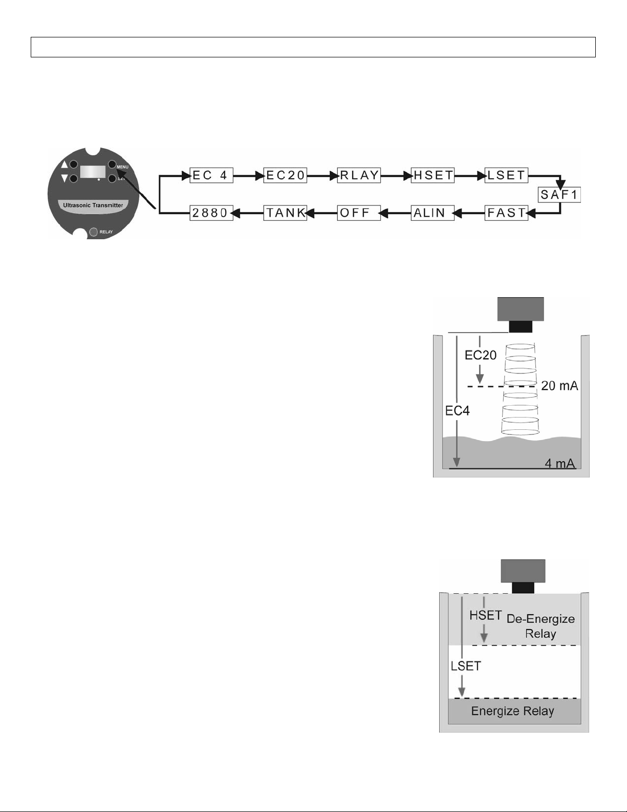
Gettingaround:LVU‐301/‐303 Series isconfigured by theuseof four pushbuttons(UP, DOWN, MENUand
SET)andaLCDdisplay.Thedisplaywillalwaysreadthedistancefromthebottomofthesensortothesurface
oftheliquid(airgap).
MainMenu:HoldingdowntheMENUbuttonwillscrolldownthemainmenuoftheLVU‐301/‐303Series.
Definitions:AllmeasurementusedforconfigurationoftheLVU‐301/‐303Seriesaremadefromthebottomof
thetransmitterdown.
EC4:This is the 4 mA setting for the LVU‐301/‐303 Series.The EC4 is the
distancefromthebottomofthetransmittertothe4mAsetpoint.Typically,
theEC4or4mAsetting isatthebottomof thetank.Thefurtherawayfrom
thesensor, thelarger thenumber willbe.Thissettingismeasuredineither
inchesorcentimetersonthedisplay.
EC20:Thisisthe20mAsettingfortheLVU‐301/‐303Series.TheEC20isthe
distance from the bottom of the transmitter to the 20 mA set point.
Typically,theEC20 or20mA setting isatthe topofthetank.The closer to
thesensor,thesmallerthenumberwillbe.Thissettingismeasuredineither
inchesorcentimetersonthedisplay.
Reversingthe 4‐20mA signal:Settingthe EC4atthebottom ofthe tankand EC20at thetop ofthe tankwill
createa4‐20mAoutputthathas4mAatemptyand20mAatfull.Toreversethe4‐20mAsign
al,setEC4at
thetopofthetankandEC20atthebottomofthetank.
RLAY:Indicatorforthenexttwomodes.The10Arelayislatchedbetweenthe
HSETandLSETpoints.
HEST & LSET: Sets the high point and low point for relay activation.Values
arebaseduponthedistancefromthebottomofthesensordowntowardsthe
liquid.
HSET:Internal relay will de‐energize when display value is less than
theHSETvalue.
LSET:Internal relay will energize when display value is greater than
theLSETvalue.
TheHSETvalueisalwayslessthattheLSETvalue.Toactivatetherelayfromasinglepoint,setHSETandLSET
tothesamevalue.
7
Page 8
MENU/DEFINITIONS(continued) StepFour
SAF1/SAF2:Thisisthefail‐safesettingfortheLVU‐301/‐303Series.UsetheSAF_settingtodetermineafail–
safemodefor theinternalrelay.When [SAF1]isset, thewillde‐energize ifthesignal becomesLOST.When
[SAF2]isset,therelaywillenergizeifthesignalbecomesLOST.
LOST:ALOSTstatewilloccurwhenthesensordoesnotreceiveareturnsoundpulse signal.Whenthis
occurs,the displaywillshowLOSTandthecurrentoutputwill defaultto theSAF_setting.Thesensor
will remain in this condition until a valid signal is acquired.No values in the MENU can be changed
untiltheLOSTconditionhasbeenresolved.
FAST/SLOW: FAST and SLOW sets the reaction time forthe SAF1/2 setting when the sensor enters a LOST
state.[FAST]is thetypicalsettingforthesensorto operate.ThetimefortheRELAYtodefaultis30 seconds
for[FAST]modeand2.5minutesfor[SLOW]mode.
TochangetheFAST/SLOWsetting,followthestepsbelow:
1. Hold[MENU]keyuntilFASTorSLOWappearsinthedisplay.
2. Release[MENU]keyandhold[SET]keytotogglebetweenFASTandSLOW.
3. Whendesiredsettingisreached,release[SET]key.Thelastdisplaysettingwillbelockedintomemory.
ALIN:Usethis modeas anaid toleveling thesensorinstalledinaself‐aligningorrotationalbulkheadfitting.
DisplaywillshowthereturnsignalstrengthindB’s.Foropti mumalignment,firstenergizetheunitandreceive
a valid return signal.Then select the ALIN mode and adjust the LVU‐301/‐303 series until the display is
maximized.Typicalreadingsrangebetween2and60dB’s.
ON/OFF:Thisisthe actualactivationsettingfor ALIN mode.Defaultis [OFF].Set to[ON]to viewtheALIN
readings.TheALINmodemustbeturned[OFF]whenalignmentiscompleted.
ToALINasensor,followthestepsbelow:
1. Hold[MENU]keyuntilOFFappearsinthedisplay.
a. OFFwillappearrightafterALIN
2. Release[MENU]keyandimmediatelyhold[SET]keytotogglefromOFFtoON.
3. Release[SET]key.TheLV
U‐301/‐303seriesisnowinALINmode.
4. Adjustthesensorsothedisplayshowsthelargestvalue.
a. Whenthehighestvalueisshown,lockthesensorinplace.
5. ToexitALINmode,repeatsteps1‐4changingfromONtoOFF.
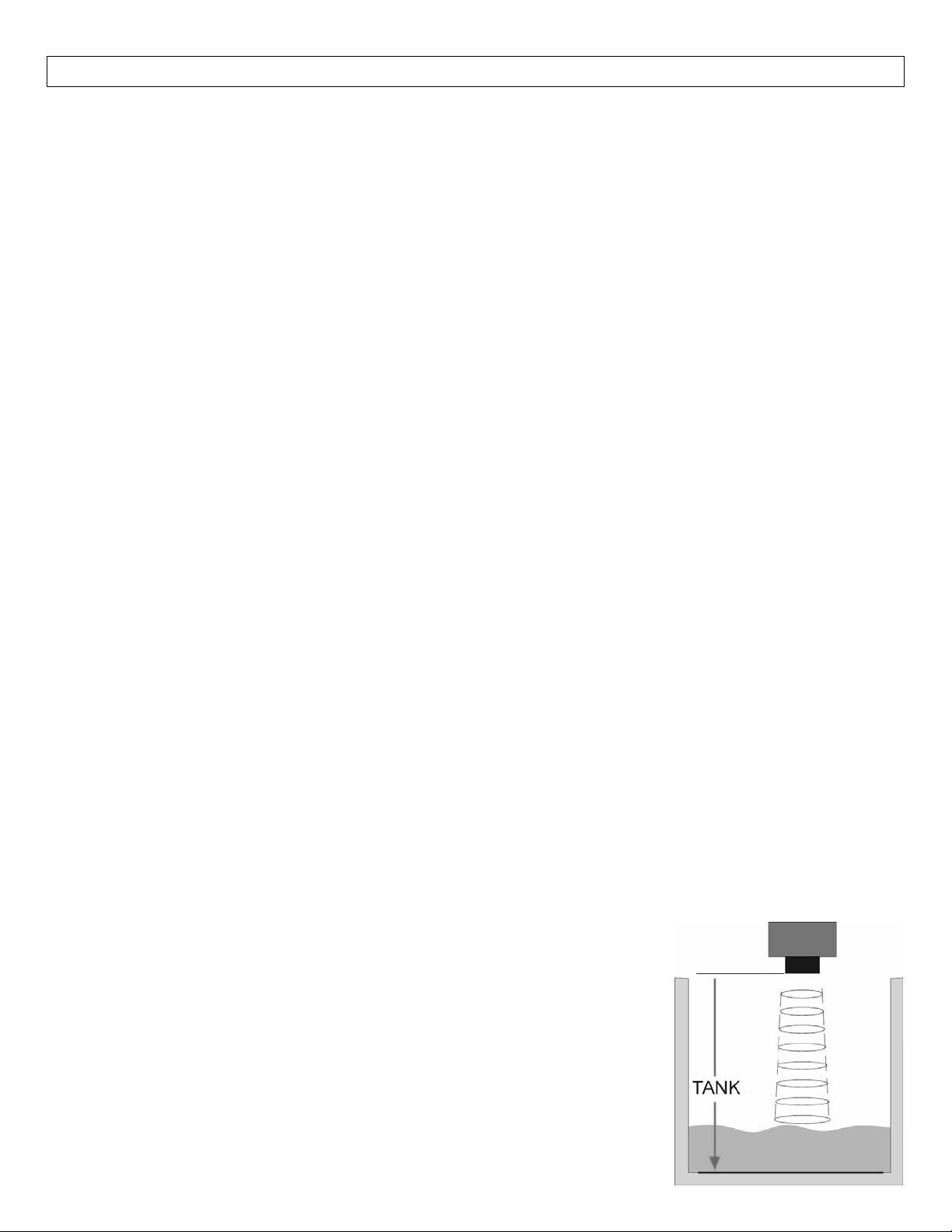
TANK:The TANK sets the maximum tank height and will filter out all returns
greaterthatthisvalue.Regardlessofhow theEC4andEC20areset,setTANK
totheEmptytankdistanceorgreater.
(VALUE):ThenumberafterTANKshowsthesettingforTANK.Thisvalueisthe
actual TANK setting that can be changed for the application.The maximum
distanceis300.0inches.
8
Page 9
CONFIGURATION StepFive
StepsforBasicConfiguration:
1. SelectandSettheunitsofoperation.
2. ConfiguretheSensor’sCurrentRangeusingtheEC4andEC20settingsinthemainmenu.
a. Thetankleveldoesnotneedtobeemptyorfullforthisoperation.
3. ConfiguretheRelaylevelsettingsusingtheHSETandLSETsettingsinthemainmenu.
a. Thetankleveldoesnotneedtobeemptyorfullforthisoperation.
4. SettheOperationalRangeusingtheTANKsettingsinthemainmenu.
a. Thetankleveldoesnotneedtobeemptyorfullforthisoperation.
5. SelecttheFail‐SafesettingusingtheSAF_settinginthemainmenu.
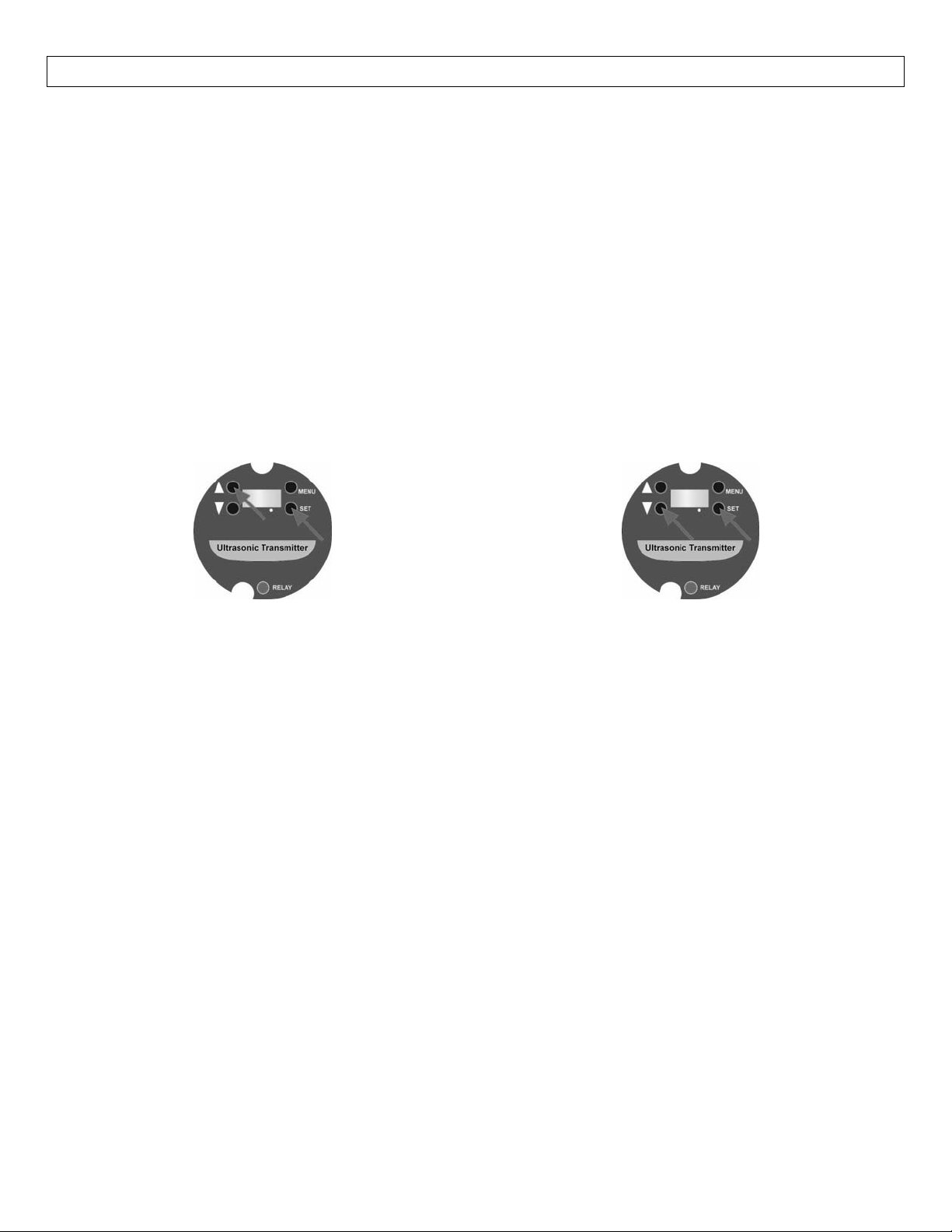
SelectingUnitsofOperation(Inches orCM):ThedefaultfortheLVU‐301/‐303Seriesistodisplayininches.If
powerisremoved,thesensorwillremainintheselectedmode.Thisoperationselectstheunitsofoperationfor
the configuration of the transmitter.This selection has no effect onthe output of the sensor.The 4‐20 mA
outputcanbescaledtoreadinanyengineeringunits.
Tochangetocentimeters Tochangetoinches
1. Removepowertothesensorandwait10seconds.
2. Simultaneouslypress[∆]and[SET]whileadding
powertothetransmitter.
3. Thesensorwillnowreadincentimeters.
1. Removepowertothesensorandwait10seconds.
2. Simultaneouslypress[]and[SET]whileadding
powertothetransmitter.
3. Thesensorwillnowreadininches.
ConfiguretheSensor’sCurrentRangeusingEC4andEC20
EC4:Allmeasurementusedforconfigurationofthesensoraremadefromthebottomofthetransmitterdown.
1. MeasurethedistancefromthebottomofthesensortothedesiredEC4setpoint.
2. Hold[MENU]keyuntilEC4appearsindisplay.
3. Release[MENU]keyandwaituntilavalueappears.
a. Thevaluethatappearsisthecurrentdistancefromthesensortothesurfaceoftheliquid.
4. Immediatelypressthe[∆]or[]keystoviewthememoryvalueforEC4.
5. Usethe[∆]or[]keystoraiseorlowerthedisplaytothedesiredvalue.
a. Ifthekeysremainuntouchedformorethan3seconds,thesensorwillexitthemenu.
6. Pressthe[SET]keytoenterthisvalueasthenewEC4setpoint.
EC20:Allmeasurementusedforconfigurationofthesensoraremadefromthebottomofthetransmitterdown .
1. MeasurethedistancefromthebottomofthesensortothedesiredEC20setpoint.
2. Hold[MENU]keyuntilEC20appearsindisplay.
3. Release[MENU]keyandwaituntilavalueappears.
a. Thevaluethatappearsisthecurrentdistancefromthesensortothesurfaceoftheliquid.
4. Immediatelypressthe[∆]or[]keystoviewthememoryvalueforEC20.
5. Usethe[∆]or[]keystoraiseorlowerthedisplaytothedesiredvalue.
a. Ifthekeysremainuntouchedformorethan3seconds,thesensorwillexitthemenu
.
6. Pressthe[SET]keytoenterthisvalueasthenewEC20setpoint.
9
Page 10
CONFIGURATION(continued) StepFive
SettheRELAYusingHSETandLSET
HSET:Allmeasurementusedforconfigurationofthesensoraremadefromthebottomofthetransmitterdown.
1. MeasurethedistancefromthebottomofthesensortothedesiredHSETsetpoint.
2. Hold[MENU]keyuntilHSETappearsinthedisplay.
3. Release[MENU]keyandwaituntilavalueappears(thisisthememoryvalueforHSET).
4. Usethe[∆]or[]keystoraiseorlowerthedisplaytothedesiredvalue.
a. Ifthekeysremainuntouchedformorethan3seconds,thesensorwillexitthemenu.
5. Pressthe[SET]keytoenterthisvalueasthenewHSETsetpoint.
LSET:Allmeasurementusedforconfigurationofthesensoraremadefromthebottomofthetrans mitte rdown.
1. MeasurethedistancefromthebottomofthesensortothedesiredLSETsetpoint.
2. Hold[MENU]keyuntilHSETappearsinthedisplay.
3. Release[MENU]keyandwaituntilavalueappears(thisisthememoryvalueforLSET).
4. Usethe[∆]or[]keystoraiseorlowerthedisplaytothedesiredvalue.
a. Ifthekeysremainuntouchedformorethan3seconds,thesensorwillexitthemenu.
5. Pressthe[SET]keytoenterthisvalueasthenewLSETsetpoint.
SetOperationalRangeusingTANK
TANK:Allmeasurementusedforconfigurationofthesensoraremadefromthebottomofthetransmitterdown.
1. MeasurethedistancefromthebottomofthesensortothedesiredMAXRsetpoint.
2. Hold[MENU]keyuntilthevalueafterMAXRappearsinthedisplay.
a. ThisvalueisthecurrentMAXRsetting.
3. Ifthisisacceptable,press[SET]tolockthevalueastheMAXRsetting.Ifnot,usethe[∆]or[]keys
toraiseorlowerthevaluetothedesiredsetting.
4. Pressthe[SET]keytoenterthisvalueasthenewMAXRsetting.
SelecttheFail‐SafeSetting
SAF_:
1. Hold[MENU]keyuntilSAF1orSAF2appearsinthedisplay.
2. Release[MENU]keyandhold[SET]keytotogglebetweenSAF1orSAF2.
3. When desired setting is reached, release [SET] key. The last display setting will be locked into
memory.
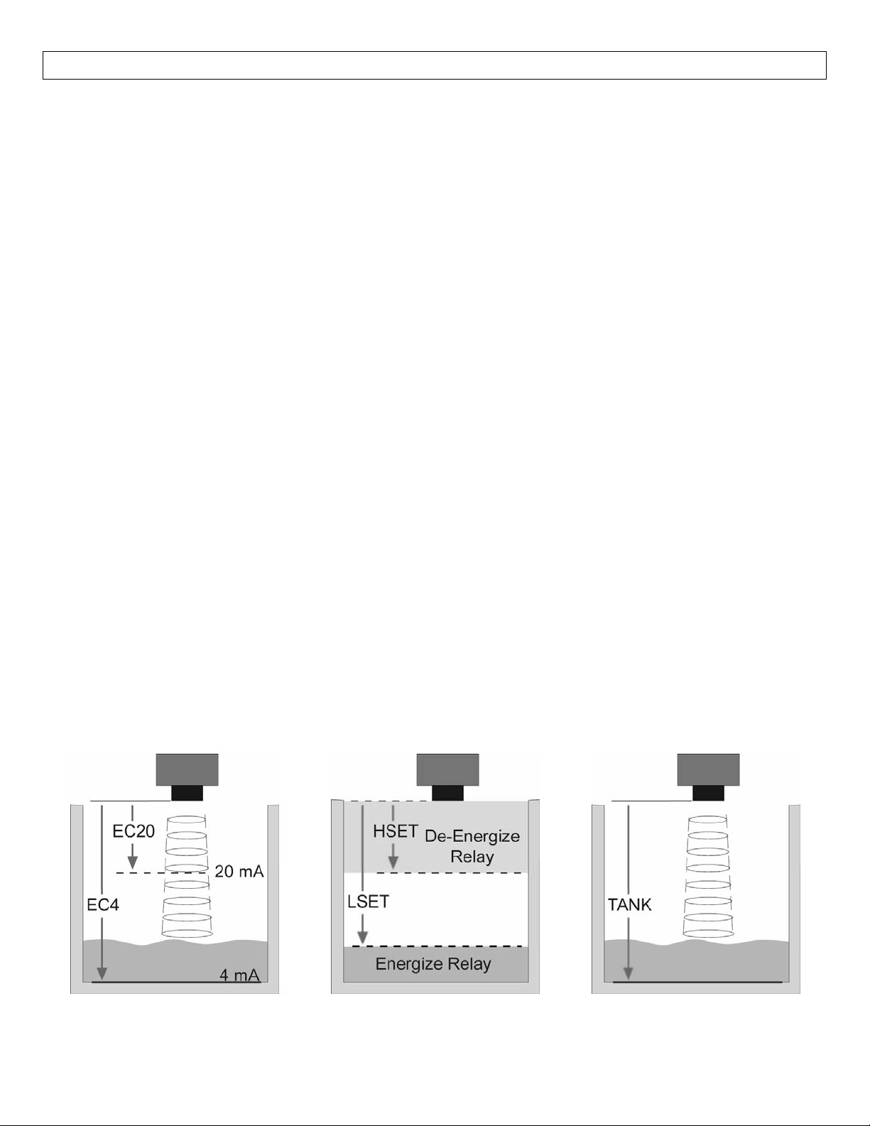
EC4andEC20Distances
ShownAbove
HSETandLSETDistances
ShownAbove
TANKDistances
ShownAbove
10
Page 11
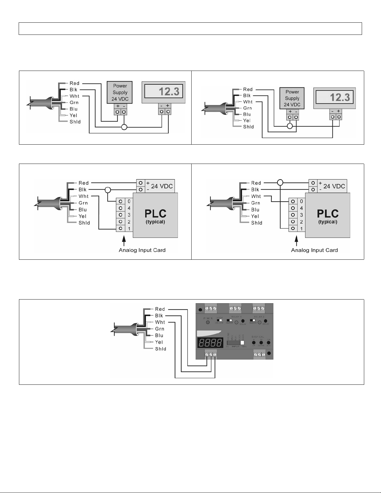
WIRING StepSix
TheLVU‐301/‐303Seriesrequires14‐36VDCpowerwithatleast200mAsupplyinordertooperate.
WiringtoGenericLoopPoweredDisplay:
SourcingLVU‐303
WiringtoGenericPLC:
SourcingLVU‐303
SinkingLVU‐301
SinkingLVU‐301
WiringtotheLVCN‐51SeriesLevelController:
Note:CheckLVCN‐51seriesmanualregardingsettingtheLVCN‐51seriestoworkwithaSourcingLVU‐303(JWB
mode)orSinkingLVU‐301(JWAmode).
11
Page 12
INSTALLATION StepSeven
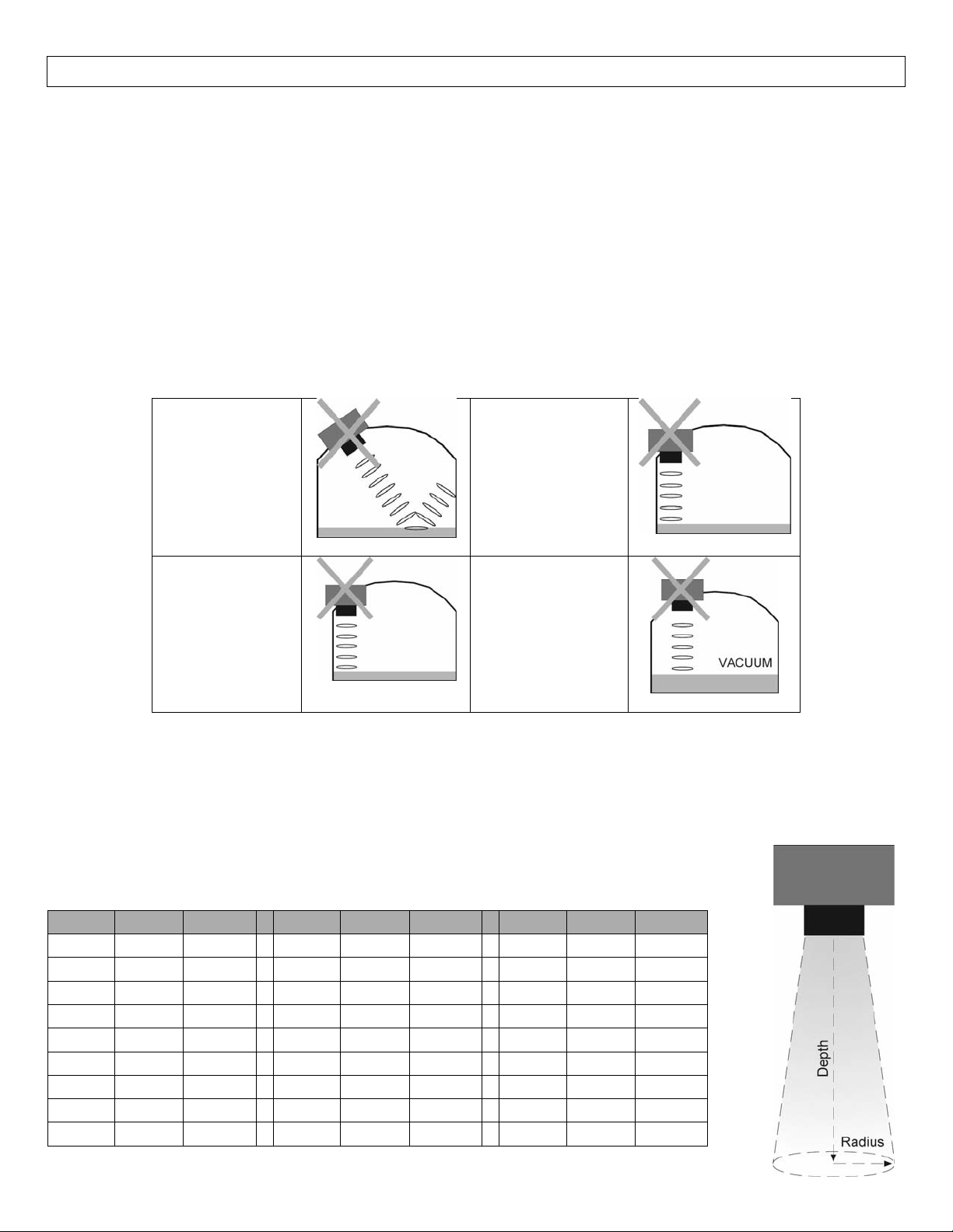
The LVU‐301/‐303 Series should always be mounted perpendicular to the liquid.Make sure that the fitting
and transmitter threads are not damaged or worn.Always hand‐tighten the transmitter within the fitting.
Performaninstalledleaktestundernormalprocessconditionspriortosystemstartup.
MountingGuide
1. Donotmountatanangle
2. Liquidshouldneverenterthedeadband
3. SideWall‐UsetheBeamWidthdatatofindtheclosestthesensorcanbetothesidewall
4. Donotmountwhereobstacleswillintrudeonsensor’sbeamwidth
5. Donotmountinavacuum
6. Avoidmountinginthecenterofadometoptank.
7. Inconebottomtank,positionthesensoroverthedeepestpartofthetank.
Donotinstall
sensoratan
AvoidInterference
fromsideoftank
angle
Donotinstall
withobjectsin
thebeam.
Donotinstallin
applicationswith
vacuum.
Installation in existing fittings:If the existing fitting is larger than the threads of the LVU‐301/‐303Series,
selectareducerbushingsuchasLVU800‐2N80(3”threadx2”thread)orLVU800‐3N80(4”threadx2”thread).
Beam Angle:LVU‐301/‐303 Series features an 8° beam angle.As the distance to the liquid increases, the
beam will increase in size.Keep any object that can interfere with the sound pulses (ex: side wall, ladders,
mixingblades,etc.)outsideofthisbeamangle.Usethedataprovidedtosizethefootprint
ofthesoundpulse.
Depth Radius Radius Depth Radius Radius Depth Radius Radius
1’ 1.2” 3.1cm 10’ 8.8” 22.3cm 19’ 16.3” 41.3cm
2’ 2.1” 5.2cm 11’ 9.6” 24.4cm 20’ 17.2” 43.6cm
3’ 2.9” 7.3cm 12’ 10.4” 26.5cm 21’ 18.0” 45.7cm
4’ 3.7” 9.5cm 13’ 11.3” 28.7cm 22’ 18.8” 47.8cm
5’ 4.6” 11.6cm 14’ 12.1” 30.8cm 23’ 19.7” 50.0cm
6’ 5.4” 13.7cm 15’ 13.0” 32.9cm 24’ 20.5” 52.1cm
7’ 6.2” 15.9cm 16’ 13.8” 35.1cm 25’ 21.4” 54.2cm
8’ 7.1” 18.0cm 17’ 14.6” 37.2cm
9’ 7.9” 20.1cm 18’ 15.5” 39.3cm
12
Page 13
INSTALLATION StepSeven
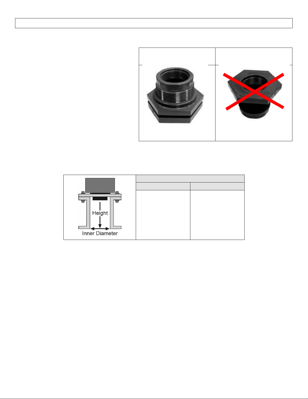
FittingSelection:LVU‐301/‐303Seriesiscommonlyinstalledintankadapters,flanges,bracketsorstandpipes.
1. Tank Adapter:Select a tank adapter
fitting, such as the LVU800‐2B for the
2”TankAdapter
SocketxThread
LVU‐301/‐303series.
a. Avoid tank adapter (thread x
thread)stylesand/orpipe stops
forward of the installed
transducer.
a. For larger tank adapters, it is
OK to use a reducer bushing
such as the LVU800‐2N80 (3”
threadx2”thread).
2. Riser:Installationswithtall,narrowriserscanimpedetheacousticsignal.
a. 2”(5cm)diameterrisersshouldbenotallerthan3”(7.6cm).Largerdiameterrisersshouldbe
notallerthan12”(30.5cm).
RiserSpecifications
InnerDiameter MaximumHeight
3”~(75mm)
4”~(100mm)
5”~(125mm)
6”~(150mm)
7”~(175mm)
8”~(200mm)
3”~(75mm)
7”~(175mm)
10”~(250mm)
12”~(300mm)
14”~(350mm)
16”~(400mm)
TankAdapter
ThreadxThread
Donotusethreadxthread
Note:Donotexceedthedimensionslistedabove
3. Flange:Ifinstalling on a flange, select a flange with a thread that is equal to the thread of the LVU‐
301/‐303Series.
a. Whenusingaflangewithariser,pleaseobservetheriserdimensionalinformationabove.
b. Ifthe size of the flange is larger than the thread of thesensor,
use areducer bushing to help
mountthesensor.
13
Page 14
INSTALLATION StepSeven
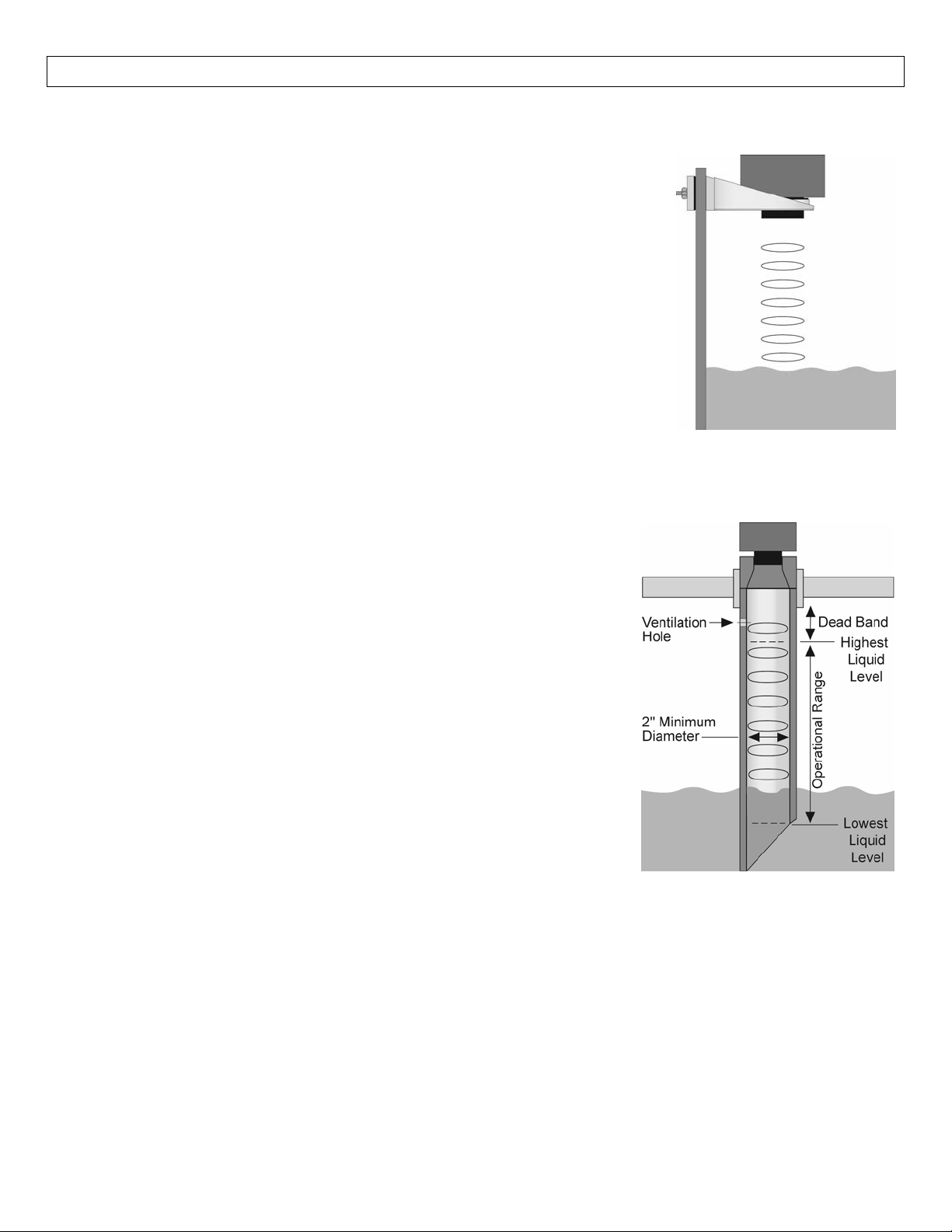
4. Side Mount Bracket: For installations in open tanks and sumps, use the LVM‐30 series side mount
bracket.
a. Be aware of the 8° beam angle with the LVU‐301/‐303 Series
transmitter.
b. Use the Beam Width data to avoid having the sensor’s beam
awayfromthesidewall.
5. Stand Pipe:A standpipe maybe used to dampen turbulence or when foam is present in the
application.
a. Pipecanbemadeofanymaterial.
b. Selectaminimum2”IDpipeforthestandpipe.
i. Alargerdiameterpipecanbeused.
c. UseacouplingandreducerbushingtoattachtheLVU‐301/‐
303Seriestothepipe.
d. Thepipe lengthshouldrunthe measurement spanandthe
bottomofthepipeshouldremainsubmergedatalltimesto
preventfoamfromenteringthepipe.
e. The pipe must be a continuous length with no joints,
couplingsorextensions.
f. Cut a 45°notch at the bottom of the pipe and drill a
1/4”pressureequalizationholeinthedeadband.
i. Theventholemustbewithinthe dead band of the
LVU‐301/‐303Series.
g. Thepumpsshouldnotdriveliquidpasttheopenendof the
standpipewhichcausestheliquidinthepipetooscillate.
14
Page 15
RELAYEXAMPLES StepEight
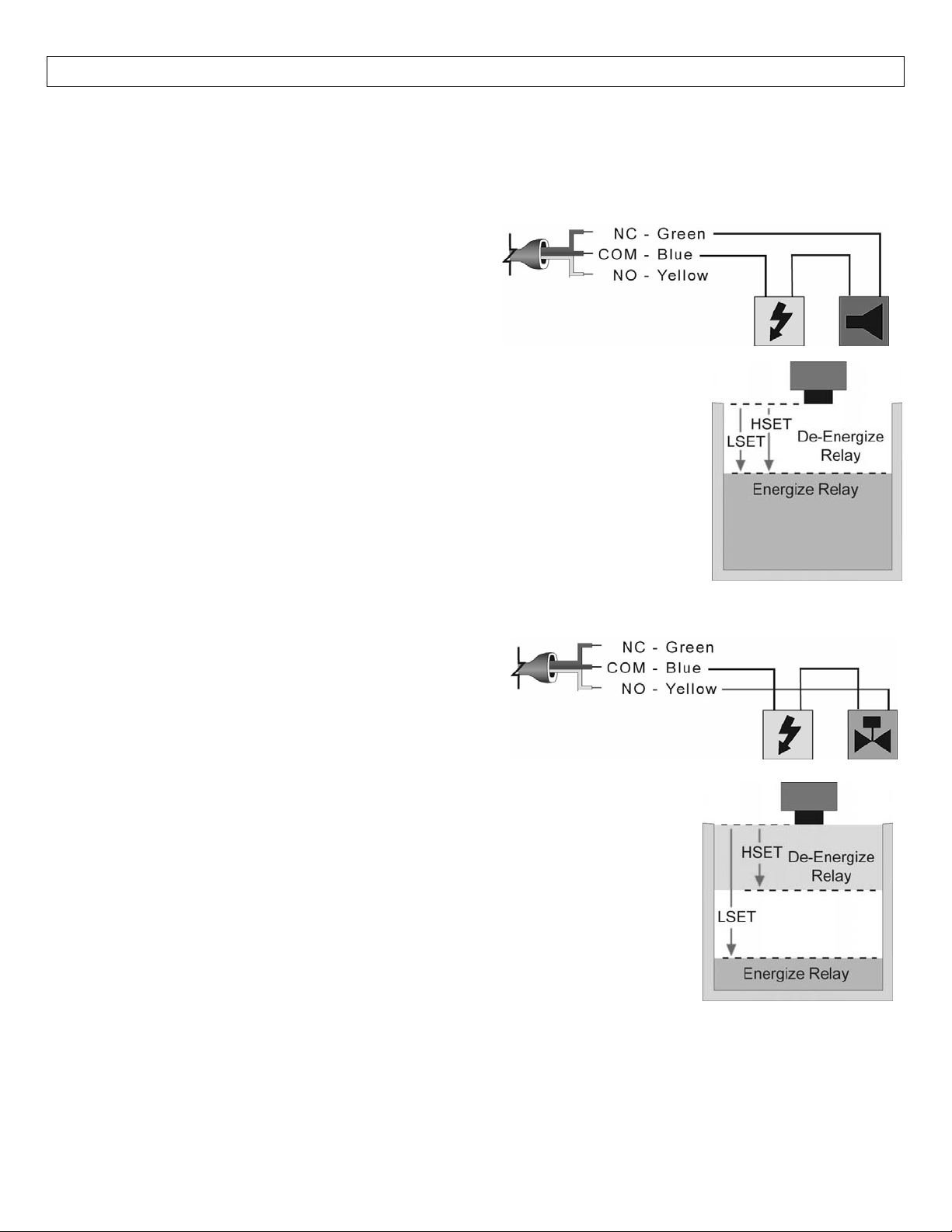
InternalRelay:TheLVU‐301/‐303 seriescontainsa 250VAC,10A internalrelay.The relayisactuated bythe
HSETandLSETsettings.Whilethismanualofferssomeexampleandsuggestionstohelpexplaintheoperation
oftherelay,suchexamplesareforinformationonlyandarenotintendedasacompleteguidetoinstallingany
specificsystem.
Ex: High Level Alarm:The goal is to make sure the
liquiddoesnotriseaboveacertainlevelinthetank.Ifit
does, an alarm sounds alerting the operator to a high
level condition.Wire a lead of the alarm to the Green
NC relay wire.Power is wired to the Blue COM relay
wire and to the other lead of the alarm to complete the loop.Please observe
polaritywiththealarm.
Make sure the HSET and LSET settings are programmed correctly.Typically the
valuesaresettothesamedistanceawayfromthesensor.ForHighAlarms,setthe
HSETvaluefirstbeforesettingtheLSETvalue.
Inthe normaloperation state,the sensor’srelaywillremainenergized,keepingthe
alarmcircuit open.Whenthe alarmlevelhasbeenreached, therelayde‐energizes
andactivatesthealarm.Tochangetoalowlevelalarm,re‐wirethealarmfromthe
GreenNCwiretotheYellowNOwireandadjusttheLSETandHSETtotherequiredlevelinthetank.
Ex:AutomaticFill:Thegoalistofillthetank.Avalveis
opened (energized) when a low level is reached and
closed(de‐energized) whena highlevelis reached.Wire
a lead from the valve to the Yellow NO wire.Power is
wiredtotheBlueCOMrelaywireandtotheotherleadof
thevalvetocompletetheloop.Pleaseobservepolaritywiththevalve.
Make sure the HSET and LSET settings are
programmed correctly.Typically they
areset withtheHSET asthevalueclosestto thesensorand theLSETasthevalue
farthestaway.Ina Fill operation, the HSETwillalways be the level wherethefill
stops and LSET will be the level where the fill starts.When the low level is
reache
d,thesystemwillstarttofillthetank.Thetankwillcontinuetofilluntilthe
levelreaches thehighpoint.Thesystemstopsfillinguntilthelowlevelisreached
again.Apumporsolenoidcanbesubstitutedfortheexactsameoperation.
Tochangetoanautomaticemptyapplication,re‐wirethesystemfromtheYellowNOwiretheGreenNCwire
andadjusttheLSETandHSETtotherequiredlevelinthetank.
15
Page 16
MAINTENANCE/ADVANCEDFEATURESStepNine
General:LVU‐303/‐303seriessensoritselfrequiresnoperiodicmaintenanceexceptcleaningasrequired.Itis
the responsibility of the user to determine the appropriate maintenance schedule, based on the specific
characteristicsoftheapplicationliquids.
CleaningProcedure:
1. Power: Make sure that all power to the sensor, controller and/or power supply is completely
disconnected.
2. SensorRemoval: In all through‐wall installations, make sure that the tankis drained well below the
sensorpriortoremoval.Carefully,removethesensorfromtheinstallation.
3. CleaningtheSensor:Useasoftbristlebrushandmilddetergent,carefullywashthesensor.Donotuse
harshabrasivessuch assteelwool orsandpaper,which mightdamagethe surfacesensor.Do notuse
incompatiblesolventswhichmaydamagethesensor’sPolypropyleneorPVDFplasticbody.
FactorySettingandFactoryReset:TheLVU‐303/‐303 series is preset at the factory.Whenpoweredup the
transmitterthefirsttime,thefactorysettingwillbeactive.Ifatanytimeyouneedtoreturntothesesettings,
remove power from the sensor and wait 10 seconds. Press the [SET] and [MENU] buttons simultaneously
whilepoweringupthetransmitter.
LEVL INCHES(cm) SAF_ SAF1
EC4 288”(731.2cm)FAST/SLOW FAST
EC20 8”(20.3cm) ALIN N/A
RLAY N/AOFF/ON OFF
HSET 5”(12.6cm) TANK N/A
LSET 288”(731.2cm) Value 216”(548.6cm)
ChangingDisplayUnits:TheLVU‐301/‐303seriescomes preset to measure in inches.Tochangethe unit to
display centimeters, remove power to the sensor and wait 10 seconds.Press [∆] and [SET] simultaneously
while powering up the transmitter.The sensor will now read in centimeters.To return to inches, remove
powerandwait10seconds.Press[]and[SET]simultaneouslywhilepoweringupthetransmitter.
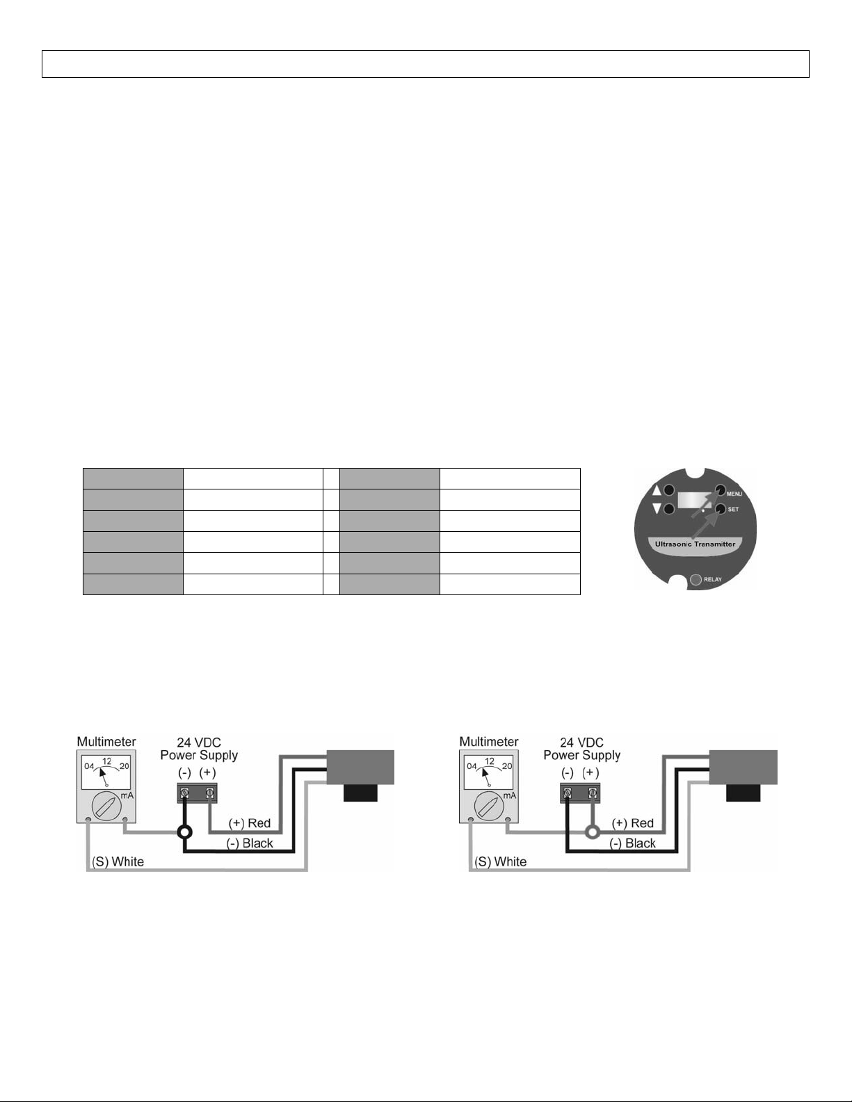
TestingtheTransmitter
SourcingTransmitter(LVU‐303Series) SinkingTransmitter(LVU‐301Series)
1. Connectamultimeterinserieswiththewhitewiretoreadthecurrentoutput.
a. Besuretoobserveintheexamplesabovewhere
theothersideofthemultimeterisconnected.
2. Verify that the current increases (tank filling) and decreases (tank emptying) appropriately in the
calibratedspan.
If not, carefully observe and attempt to correlate any installation, level or application event for more specific
troubleshootingdirection.
16
Page 17

TROUBLESHOOTING StepTen
PROBLEM SOLUTION
Transmitterindicatesa
currentof0mA
Transmitterjumpstoa
currentreadingbetween
19and20mA
Transmitterindicatesa
currentover20mA
Transmitteralwaysjumps
toLOSTcondition
Check the wiring for an open circuit (specifically the White wire).An
opencircuitisthemostcommonissuewitha0mAsignal
Check the installation of the transmitter.Bad installation fittings will
cause false signals near the top of the tank, which typically translates
to a signal between 19 and 20 mA.Also look for interference just
belowthetransmitter.Ifthe transmitter isinst
alledina metal fitting,
switchtoaplasticfitting.
Immediately check the wiring for a short circuit.The LVU‐301/‐303
Seriesiscurrentlimitedto20mA.Anythingabove20mAindicatesa
shortcircuit.
AreadingofLOSTin thedisplayofthesensor indicatesthetransmitter
isnotreceiving avalidreturn signal. IfLOSTappears, pleasecheckthe
followingtroubleshootingitems:
1. Beamconeinterferencesuchas thesidewall, ladder,seams,rungs
orpipeswithinthesensor’sbeamcone.
2. Proper installation such that the LVU
‐301/‐303 series is installed
level and free from interference from the installation fitting or
flange.
3. Sufficient power being supplied to the LVU‐301/‐303 series. The
sensorrequires14‐36VDCpowerwithaminimumsupply200mA.
4. ProperProgrammingoftheTANKfunction.For bestresults, setthe
TANK function as the distance from the bottomofthe tank to the
bottomofthetransmitter.
5. Makesurethatthe transmitterisnotinstalledatanangle.Evena5
degreeoffsetcanreducethesignalreturnstrengthgreatly.
Outputoftransmitteris
oppositeofthelevelof
liquid
ChecktheEC4&EC20Setting.
For4mAatemptytankand20mAatfulltank,theEC4mustbe
thelargervalueandtheEC20tosmallervalue.
For20mAatempty tank and 4mAatfull tank, the EC20 must
bethelargervalueandtheEC4tosmallervalue.
Outputofthetransmitter
isalwaysreadingeither
4mAor20mA
Check the input settings (EC4 and EC20) for the transmitter.The
display of the transmitter reads to the 1/10th of an inch or cm.
Example:adisplayof1234is123.4”andnot1234”.
17
Page 18
TROUBLESHOOTING StepTen
PROBLEM SOLUTION
Thedisplayonthe
transmitterdoesnot
matchthedisplayonthe
sideofthetank
Sensorappearstohave
resetitself
DisplayreadsCM8Qor
CM8O
Thedisplayforthe LVU‐301/‐303 Series will alwaysshowthedistance
from the liquidsurfacetothebottomofthesensor(ininchesorcm).
The 4‐20 mA output can be scaled to read in any engineering units,
thusthedisplayswillnevermatchunlessthelocaldisplayisconfigured
toreadtheairgapinthetank.
CheckthesettingsforEC4&EC20.Rememberthatthefirstvalueseen
inEC4&EC20isthecurrentdistancefromthesensortotheliquid.
1. TocheckEC4setting:
a. PressMENUuntilEC4appears.
b. Waituntilanumberappears.
c. Immediatelypressthe∆button&theEC4settingwillappear.
2. TocheckEC20setting:
a. PressMENUuntilEC20appears.
b. Waituntilanumberappears.
c. Immediatelypressthe∆button&theEC20settingwillappear.
These are actually firmware codes for the sensor.The appearance of
eithercodeindicatesthat the sensor is stuck in arebootstagedueto
thepowerflickeringonandoff.Checkthatthepowerbeingsuppliedis
consistentanddoesnotflickeroff.Alsocheckthewireconnectionsat
theterminals.
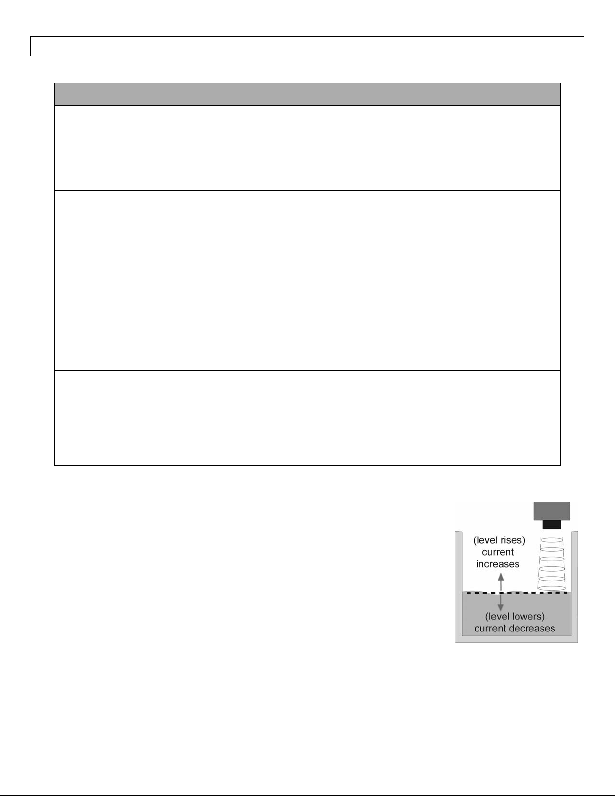
Other Hints:Current must change with all level movement. Example: For the
illustrationshown,aslevelincreases,thecurrentoutputwillincrease.Iftheoutput
oftheLVU‐301/‐303seriesisalwaysreading4mAor20mA,checktheinputvalues
(EC4andEC20)forthesensor.
Thedisplayonthe LVU‐301/‐303 Serieswillalwaysindicate the distance fromthe
bottom of the sensor to the surface of the liquid (in units of either 1/10 inch or
1/10cm).Asthe liquidlevelincreases, thevalueon the displaywilldecrease.As
theliquidleveldecreases,thevalueonthedisplaywillincrease.
18
Page 19

19
Page 20

20
 Loading...