

Page 1
Page 2

2
Page 3

INTRODUCTION/TABLEOFCONTENTS StepOne
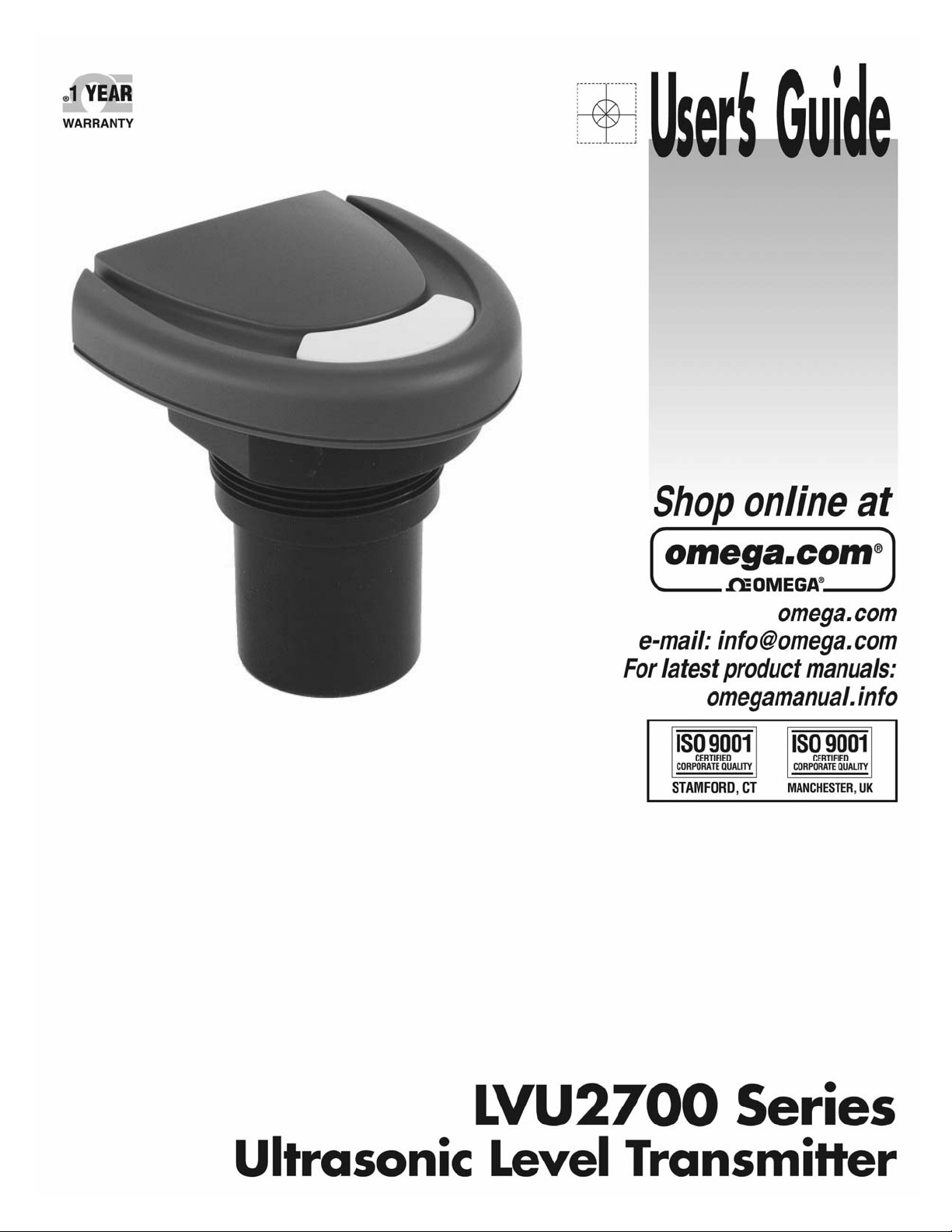
The LVU2700 Seriesisageneral‐purposeultrasonicleveltransmitter that provides a loop powered 4‐20 mA
output.The4‐20mAoutputcanbeusedtoprovidetheproportionallevelofliquidinanytankorvessel.The
signalcanbeconnectedtoanydevicethatacceptslooppowered4‐20mAsignals,suchasaPLC,SCADA,DCS,
display,controller,etc.
NewFeatures
Easilychangeoutputfromdistancetovolume
Selectfrom6standardtankshapes
16pointstrappingtableforcustomer/oddsizetanks
AllwithinthesimpleconfigurationPCSoftwareProgram(LVCN414‐SW)
TableofContents
Specifications/Dimensions..............................................................................................................................4
SafetyPrecautions............................................................................................................................................5
Components ...................................................................................................................................................6
GettingStarted..................................................................................................................................................7
USB®FobInterface...............................................................................................................................7
LVCN414‐SWSoftware..........................................................................................................................8
1.Configuration........................................................................................................................9
DimensionalEntry–VerticalCylinderExample.........................................................12
DimensionalEntry–Horizontal
3.LevelConfiguration.............................................................................................................16
4.WritetoUnit.......................................................................................................................16
Wiring .................................................................................................................................................17
WiringDiagram&WireConnections.................................................................................................17
WiringtoDisplays,Controller’s&PLC’s............................................................................................19
Installation .................................................................................................................................................20
MountingGuide..................................................................................................................................20
FittingSelection..................................................................................................................................21
TankAdapters&Risers:..........................................................................................................21
Flanges&SideMountFittings................................................................................................22
StandPipe...............................................................................................................................23
AdvancedFeature...........................................................................................................................................24
Appendix .................................................................................................................................................25
SampleProgram.................................................................................................................................25
UpdatingSoftware..............................................................................................................................26
UpdatingTransmitterFirmware.........................................................................................................27
StrappingTable...................................................................................................................................28
Linervs.Non‐Linear...........................................................................................................................29
FactoryDefaults..................................................................................................................................31
DemoPage.........................................................................................................................................32
Troubleshooting..................................................................................................................................33
UserSettings
2.TankShapeSelection..........................................................................................................11
CylinderwithEndcapsExample...............................14
.......................................................................................................................................34
3
Page 4
SPECIFICATIONS/DIMENSIONS StepTwo
Range:
Accuracy: ±0.2%ofrange
Resolution: LVU2710:0.019”(0.5mm)
LVU2718:0.039”(1mm)
LVU2726:0.079”(2mm)
LVU2726:0.079”(2mm)
Deadband: LVU2710:4”(10cm)
LVU2718/26/32:8”(20cm)
Beamwidth: LVU2710:2”(5cm)
LVU2718/26/32:3”(7.6cm)
Configuration: LVCN414‐SW(software)PC
Windows®USB2.0
Memory: Non‐volatile
Supplyvoltage: 24VDC(loop)
Consumption: 0.5W
Loopresistance: 500Ohms@24VDC
Signaloutput: 4‐20mA,two‐wire
Signalinvert: 4‐20mAor20‐4mA
Signalfail‐safe: 4mA,20mA,21mA,
22mAorholdlast
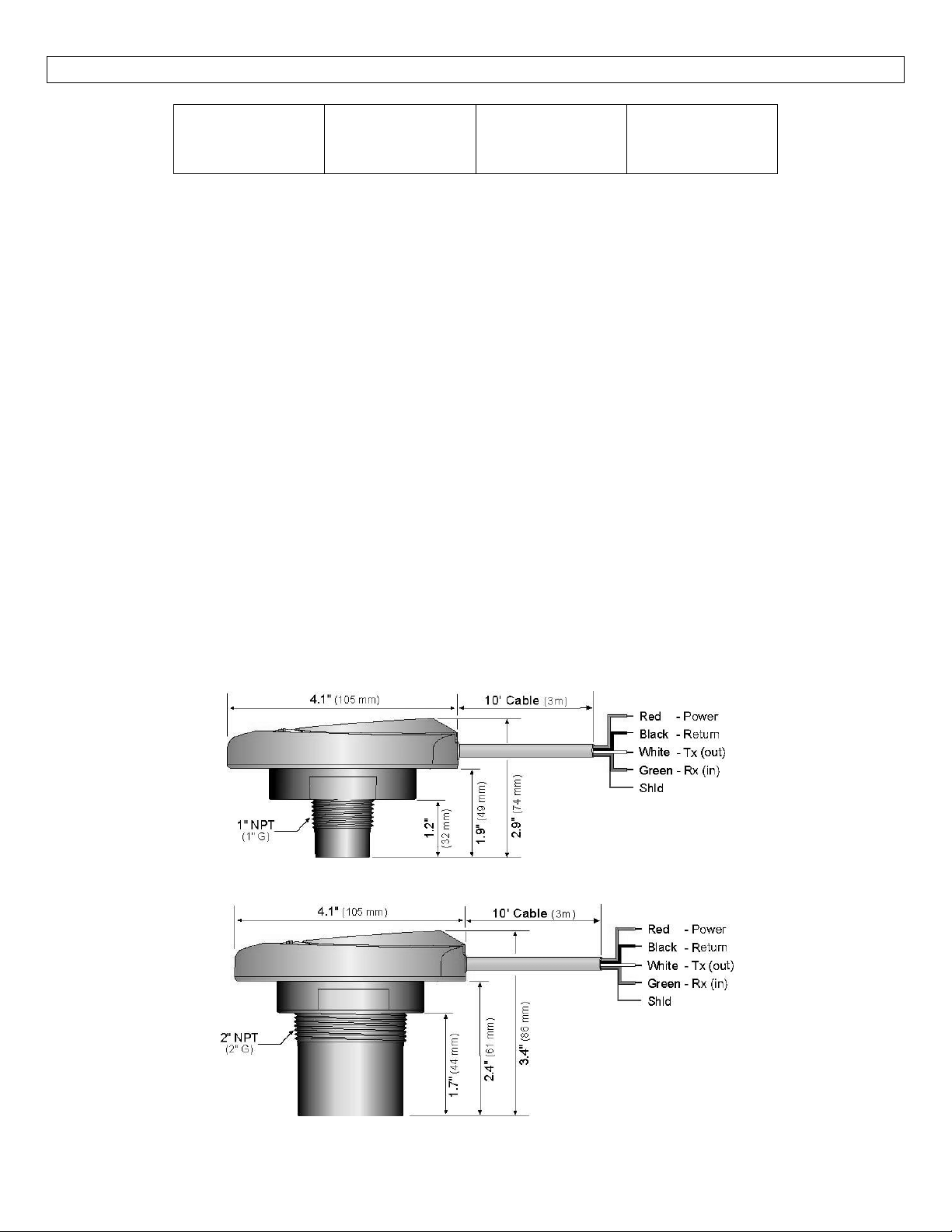
Dimensions:
LVU2710:
4"to8'
(10cmto3m)
LVU2718:
8"to9.8'
(20cmto5.5m)
SideView/LVU2710Series
LVU2726:
8"to26.2'
(20cmto8m)
Processtemp.: F:‐4°to140°
C:‐20°to60°
Temp.comp.: Automatic
Ambienttemp.: F:‐31°to140°
C:‐35°to60°
Pressure: MWP=30PSI
Enclosuretype: Type6Pencapsulated,corrosion
Encl.material: Polycarbonate
Trans.material: PVDF
Cablejacketmat.:Polyurethane
Cabletype: 4‐conductorshielded
Cablelength: 10’(3m)
Processmount: LVU2710:1”NPT(1”G)
LVU2718/26/32:2”NPT(2”G)
Mount.gasket: FKM
Classification: Generalpurpose
Compliance: CE,RoHS
LVU2732:
8"to32.8'
(20cmto10m)
resistance&submersible
SideView/LVU2718,LVU2726andLVU2732Series
4
Page 5

SAFETYPRECAUTIONS StepThree
Aboutthis Manual:PLEASEREADTHEENTIRE QUICKSTART PRIORTOINSTALLINGORUSING THISPRODUCT.
This manual includes information on the LVU2700 Series Ultrasonic Level Transmitter from OMEGA
ENGINEERING. Please refer to the part number located on the switch label to verify the exact model
configuration,whichyouhavepurchased.
User’s Responsibility for Safety:OMEGA ENGINEERING manufactures a broad range of level sensing
technologies. While each of these sensors is designed to operate in a wide variety ofapplications, it is the
user’sresponsibilitytoselectasensormodelthatisappropriatefortheapplication,installitproperly,perform
tests of the installed system, and maintain all components. The failure to do so could result in property
damageorseriousinjury.
ProperInstallationandHandling:Onlyprofessionalstaffshouldinstalland/orrepairthisproduct.Installthe
transmitter with the included FKM gasket and never over tighten the transmitter within the fitting.Always
checkforleakspriortosystemstart‐up.
WiringandElectrical:Asupplyvoltageof12to28VDCisusedtopowertheLVU2700Series.Electricalwiring
ofthetransmittershouldbeperformedinaccordancewithallapplicablenational,state,andlocalcodes.
Material Compatibility:The enclosure is made of Polycarbonate (PC).The transducer is made of
PolyvinylideneFluoride(PVDF).Makesurethatthemodel,whichyouhaveselected,ischemicallycompatible
withtheapplicationmedia.
Enclosure:Whilethe transmitter housing isencapsulated,corrosion resistance & submersible,theLVU2700
Series is not designed to be operational when immersed.It should be mounted in such a way that the
enclosure and transducer do not come into contact with the application media under normal operational
conditions.
Safety
Installationshouldbedonebyproperlytrainedstaff
Supplyvoltageshouldneverexceedamaximumof28VDC
Makesurethesensorischemicallycompatiblewithyourapplication
Designafail‐safesystemthataccommodatesthepossibilityofsensorand/orpowerfailure.
Thissensorshouldnotbeusedinclassifiedhazardousenvironments
MakeaFail‐Safe System:Designafail‐safesystem that accommodatesthepossibility of transmitterand/or
power failure.OMEGA ENGINEERING recommends the use of redundant backup systems and alarms in
additiontotheprimarysystem.
Flammable,Explosive
hazardousenvironments.
orHazardousApplications:LVU2700Seriesshouldnotbeusedwithinclassified
Warning: Always use the FKM gasket when installing the LVU2700 Series, and make sure that all electrical
wiring
oftheswitchisinaccordancewithapplicablecodes.
5
Page 6
Components StepFour
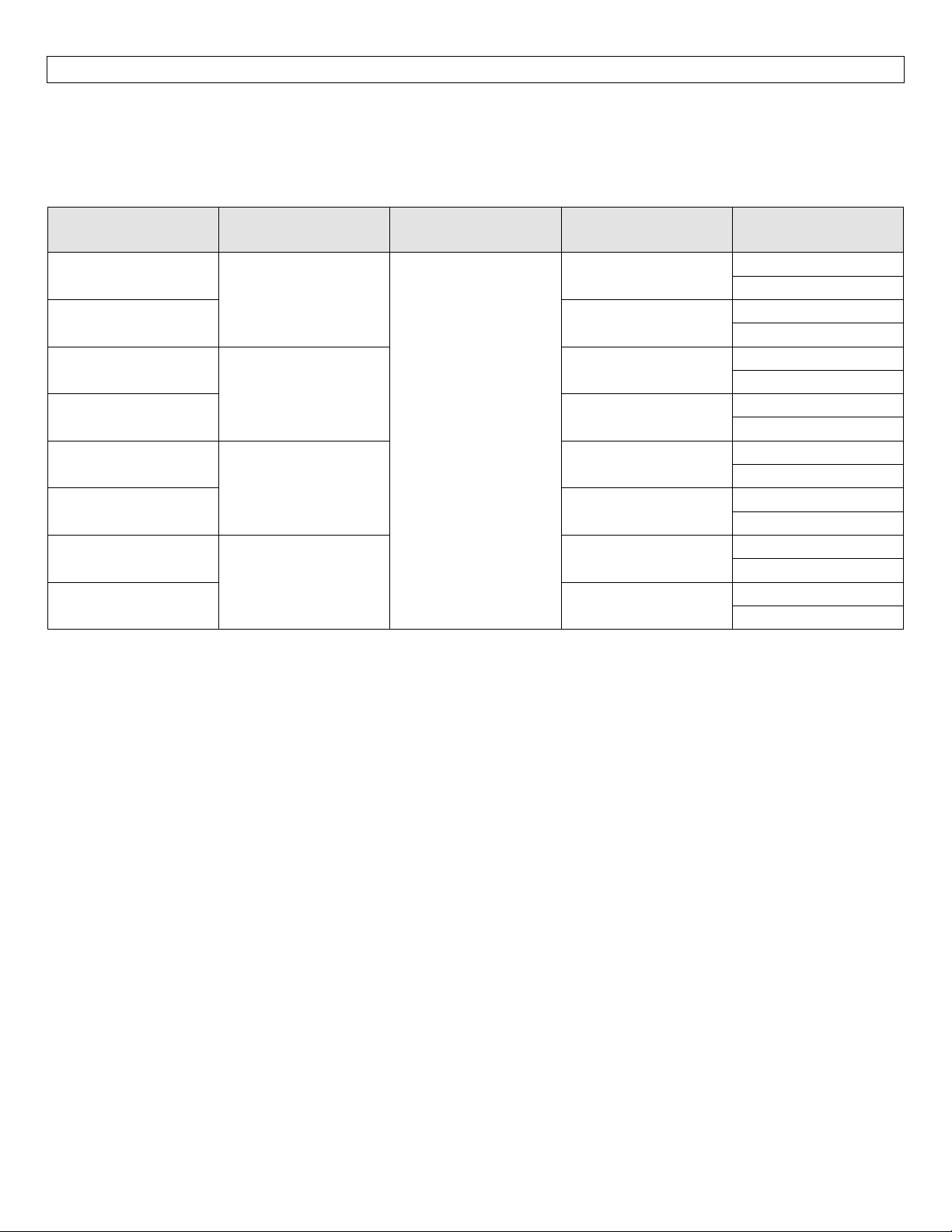
LVU2700Series isoffered infour differentmodels.Dependingonthemodelpurchased,youmayormaynot
have been shipped all the components shown below.You do however, need an LVU2700 Series, USB® Fob
andFKMgaskettoconfigure,installandoperateLVU2700Series.
LVU2700Series
PartNumber Range Enclosure MountingThread USB®Fob
LVU2710
LVU2710‐B
LVU2710‐G
LVU2710‐G‐B
LVU2718
LVU2718‐B
LVU2718‐G
LVU2718‐G‐B
LVU2726
LVU2726‐B
LVU2726‐G
LVU2726‐G‐B
LVU2732
LVU2732‐B
LVU2732‐G
LVU2732‐G‐B
FKMGasket
o Part#200128forLVU2710series
o Part#200129forLVU2718,LVU2726orLVU2732series
USB®Fob
o Part#LVCN414‐USB
Manual
9.8’
(3m)
18.0’
(5.5m)
Type6P
enclosure
26.2’
(8m)
32.8’
(10m)
1”NPT
1”G
2”NPT
2”G
2”NPT
2”G
2”NPT
2”G
Included
NoFob
Included
NoFob
Included
NoFob
Included
NoFob
Included
NoFob
Included
NoFob
Included
NoFob
Included
NoFob
6
Page 7
GETTINGSTARTED StepFive
LVU2700 Series is configured through a PC software program (LVCN414‐SW).The LVCN414‐SW is a free
download from Omega Engineering’s website.You must download and install the LVCN414‐SW prior to
pluggingintheUSB®Fob.
Pleasegotohttp://www.omega.com/ftp.
ClickonFlow,Level,pH,Environmental,andPressureSectionandpressonProducts
SelecttheLVCN414folder
Selecttheinstaller‐LVCN414InstallerverXpXX.zip
o Thiswilldownloadtheinstallerontoyourcomputer.
o Oncecompleted,runtheinstaller.
LVCN414‐SWSoftwareSystemRequirements
Windows®2000,XP,Vista,7,8
32or64‐bitsystem
1USB®2.0port
10mBharddrivespace
256mBRAM
Internetconnection
USB®FobInterface
LVU2700 Series communicates with the LVCN414‐SW PC software through a USB® interface called a Fob.
Before plugging your Fob intoyour computer’s USB® port, be sure that you haveinstalled LVCN414‐SW on
yourcomputer.
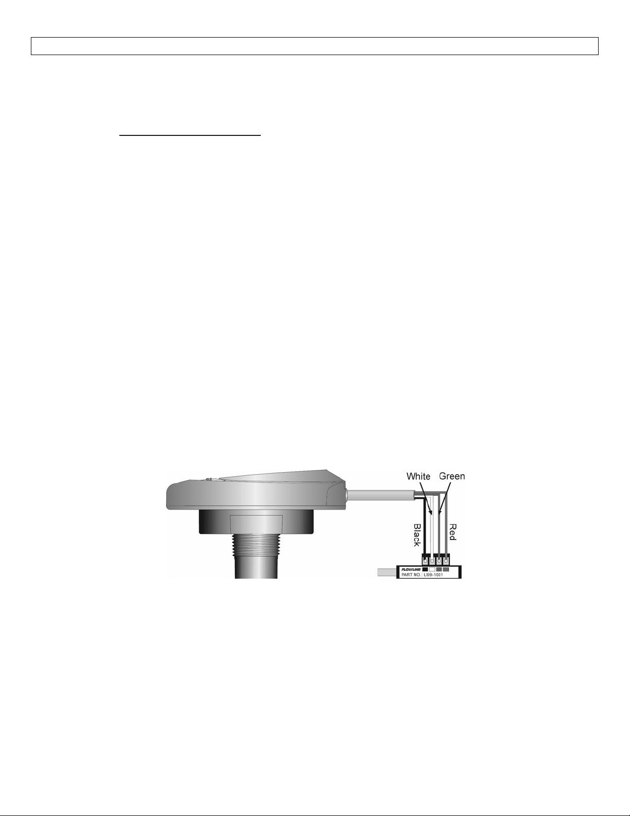
Connect the red, green, white and black wires from LVU2700 Series into the correct terminals on the Fob.
TightenthescrewsontheterminalsandplugyourFobintotheUSB®portofyourcomputer.
Themaximumcabledistancebetweenthecomputerandsen
theLVU2700Series.
Once the sensor is configured and prior to installation, isolate the white and green wires from active
powertopreventashortoftheconfigurationcircuit.
Note: When using the USB® Fob, do not add VDC or VAC power.The USB® Fob, when connected to the
computer,willprovidethereq
uiredpowertotheLVU2700Series.
7
soris15’.Thisonlyapplieswhenconfiguring
Page 8
GETTINGSTARTED(continued) StepFive
LVCN414‐SWPCSoftware
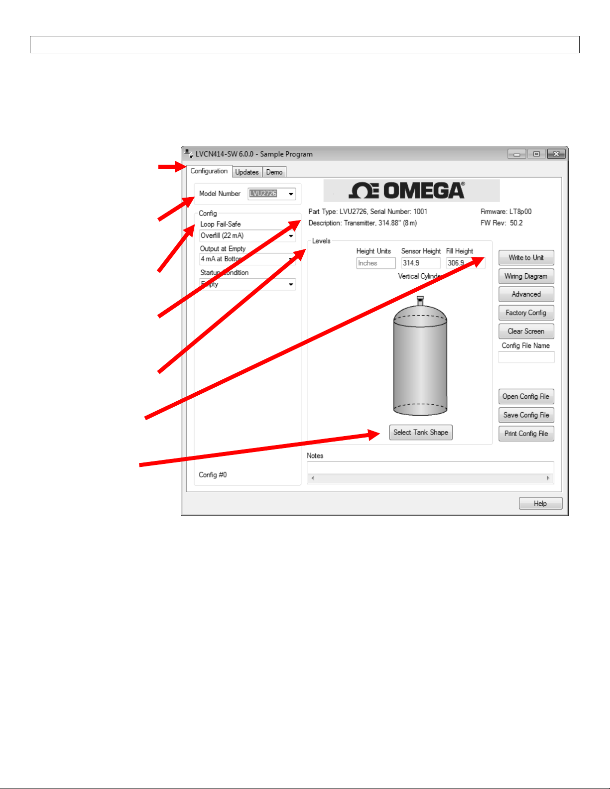
WithLVU2700Seriesconnectedtoyourcomputer,openthesoftwarebyclickingontheLVCN414‐SWicon.
Followsteps1‐3toconfigurethetransmitter.Click“Help”inthelowerrighthandcornerandopenthehelp
menuofthesoftwareforadditionalinstructions.IfyouneedadditionalassistanceusingtheLVCN414‐SW
software,pleasecontactanOmegaEngineeringApplicationsengineer.
TabsforConfiguration,
UpdatesandDemomode
ModelSelector
(SampleProgramOnly)
ConfigurationSelector
SensorDetails
LevelConfiguration
ActionButtons
TankSelector
AboveScreenCaptureisfortheLVU2726series.
ConfiguringLVU2700SerieswithLVCN‐414‐SWSoftware
1. Configuration
a. ConfigurestheLoopFail‐Safe,OutputatEmpty(4‐20mAor20‐4mA)andStartupCondition.
2. TankShapeSelection
a. Definestheshapeofthetankaswellasthedimensionalinformationforthetankwithrespect
tothesensor’slocationonthetank.
3. LevelConfiguration
a. Entersthedist
4. WritetoUnit
a. Uploadstheconfigurationintothesensor.
b. Providesacustomwiringdiagram.
ancevaluesfortheoperationalrangeofthesensor.
8
Page 9
GETTINGSTARTED(continued) StepFive
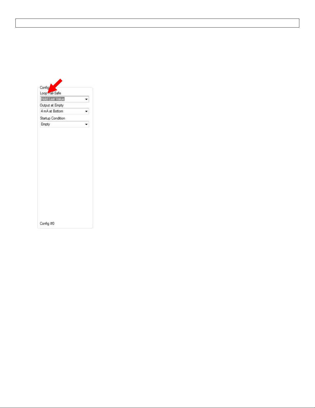
1.Configuration
Thissectionofthesoftwareiswhereyouselecttheapplication’sconfigurationsettings.Startfromthetop
andworktothebottom,choosingtheselectionsthatareapplicabletoyourconfiguration.“NotApplicable”
willautomaticallyshowwhenaselectiondoesn’tapplytoyourconfigurationsettings,andyoumaymoveon.
Allconfigurationsettingsmustbeselectedorhave“NotApplicable”beforeyoucancontinue.Note:Pressing
theClearScreenbuttonwillresettheconfigurationtableandallowaccesstoallofthefeatures.
LoopFail‐Safe
Thisfeatureallowsyoutoselectthefail‐safecurrentoutputifthe
sensorfailstodetectareturnsignal(LOST).Whenthesensorregains
signal,theoutputcurrentwillrevertbacktothecurrentlevel
condition.
o HoldLastValue‐Theoutputwillremaininthesamestateas
thelastechodetected.Example:Iftheoutputwas6.7mAjust
priortotheLOSTsignal,thedevicewillcontinuetooutput6.7
mA.Whenthesensorregainssignal,theoutputwillindicate
thelevelwhenthesignalwasregain.
o Empty‐TheoutputwillreverttothecurrentvalueofanEmpty
tank.TheemptystateisdependentupontheOutputatEmpty
setting.When4mAatBottomisselected,thesensorwill
output4mAwhenafail‐safeconditionoccurs.If20mAat
Bottomisselected,thesensorwilloutput20mAwhenafail‐
safeconditionoccurs
o Full‐TheoutputwillreverttothecurrentvalueofaFulltank.
ThefullstateisdependentupontheOutputatEmptysetting.
Note:Rightclickonanymenuthatyoumayhavequestionsontoopenthehelpmenu.
Note:Toreset,presstheClear
Screenbutton.
When4mAatBottomisselected,thesensorwilloutput20mA
whenafail‐safeconditionoccurs.If20mAatBottomis
selected,thesensorwilloutput4mAwhenafail‐safecondition
occurs
o Overfill(21mA)‐Theoutputcurrentwillgoto21mAwhenthe
returnsignalislost.
o Overfill(22mA)‐Theoutputcurrentwillgoto22mAwhenthe
returnsignalislost.
9
Page 10
GETTINGSTARTED(continued) StepFive
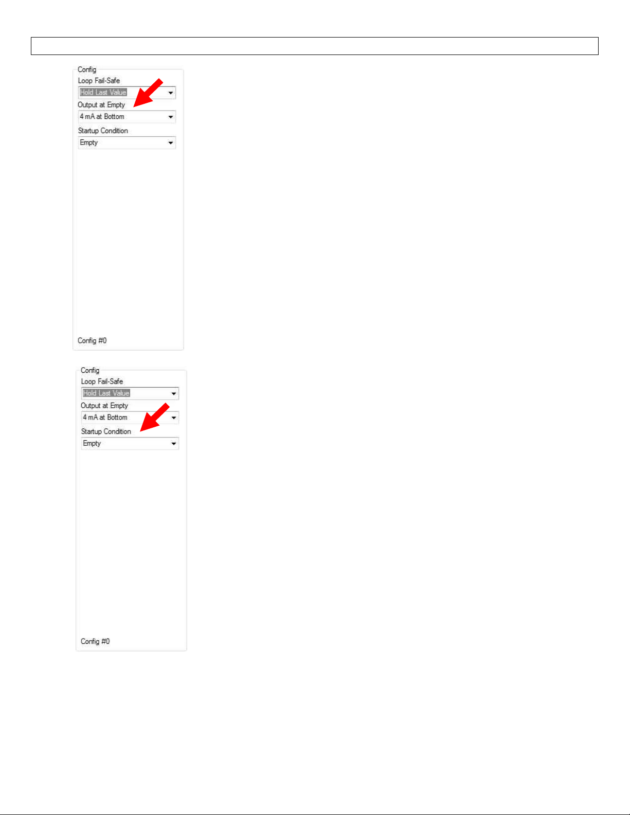
OutputatEmpty
Thisfeatureallowsyoutoselecttheorientationofthe4to20mA
output(4to20mAor20to4mA).Choosewhichoutputsettingbest
fitstheapplication.Typicalinstallationsaresetwith4mAatBottom.
Thiswillnotaffecttheperformanceofthesensorotherthanthe
outputoftheLVU2700Series.Thesoftware’sfactorydefaultis4mAat
bottomand20mAattop.Whenconnectingyoursensortoadisplay,
youmustaccountforyouroutputsettings.
o 4mAatBottom‐Theoutputcurrentwillbe4mAwhenthe
sensormeasuresanemptytankand20mAwhenthesensor
measuresafulltank.
o 20mAatBottom‐Theoutputcurrentwillbe20mAwhenthe
sensormeasuresanemptytankand4mAwhenthesensor
measuresafulltank
StartupCondition
Thisfeatureallowstheoperatortoselecttheoutputcurrenton
initialstartuppriortoacquiringatruereturnsignal(level
measurement).Thisonlyoccursduringtheinitialpoweringof
LVU2700Seriesandthetransmitterwillreverttothecorrectlevel
readingwhenthelevelisacquired.
o Empty‐SelectsthestartupcurrentestablishedinOutputat
Empty.Example:Select4mAatBottom,theoutputwill
remainat4mAuntiltheunitacquiresatruereturnecho.
Select20mAatBottom,theoutputwillremainat20mA
untiltheunitacquiresatruereturnecho.
o MidTank‐Whenselected,thestartupcurrentwillread12
mAuntiltheunitacquiresatruereturnecho.
FullTank‐Usestheoppositecurrentthatwasselectedin
o
OutputatEmpty.Example:Ifyouselect4mAatBottomthen
thestartupcurrentwouldbe20mA.Ifyouselect20mAat
Bottomthenthestartupcurrentwouldbe4mA.
o
Overfill(22mA)‐Theoutputatstartupwouldbe22mA.This
Note:Rightclickonanymenuthatyoumayhavequestionsontoopenthehelpmenu.
Note:Toreset,presstheClear
Screenbutton.
conditionwillremainuntiltheunitacquiresatruereturn
echo.
10
Page 11
GETTINGSTARTED(continued) StepFive
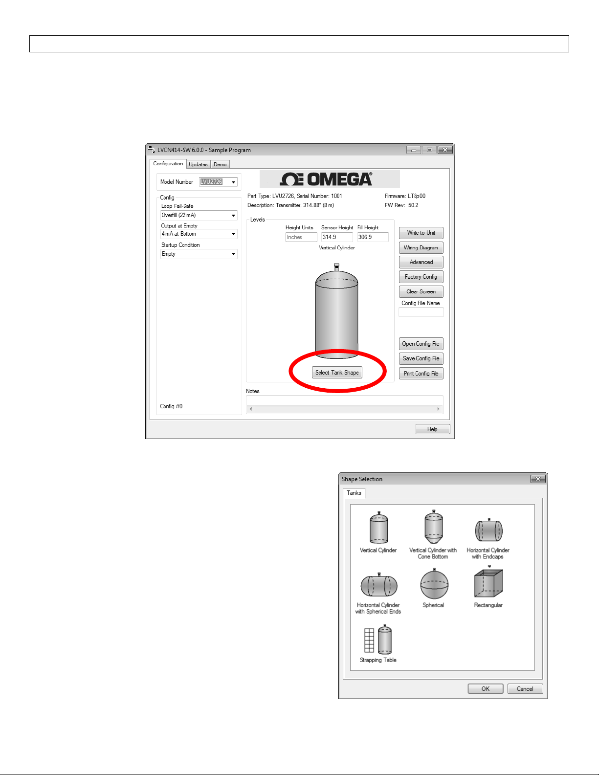
2.TankShapeSelection
The sensor may be configured in volumetric units (Gallons or Liters) or Distance (Height of Liquid) units
(inches,cm, feetor meters).The LVCN‐414‐SWsoftware willdefaultinDistance(Height ofLiquid)withunits
of Inches.To change the units or to change from Distance to Volume, press the Select Tank Shape button
locatednearthecenterofthewindow.
ShapeSelectionWindow:ThiswindowwillshowsthedifferenttankshapeoptionsavailableinWebCal™.
VerticalCylindrical
VerticalCylindricalwithConeBottom
HorizontalCylindricalwithEndcaps
HorizontalCylindricalwithSphericalEnds
Spherical
Rectangular
Strapping Table – Use this feature for manual entry
ofmeasuredtankdistancesandvolumes.
Select any of the above tank shapes and press OK to
confirm.
11
Page 12
GETTINGSTARTED(continued) StepFive
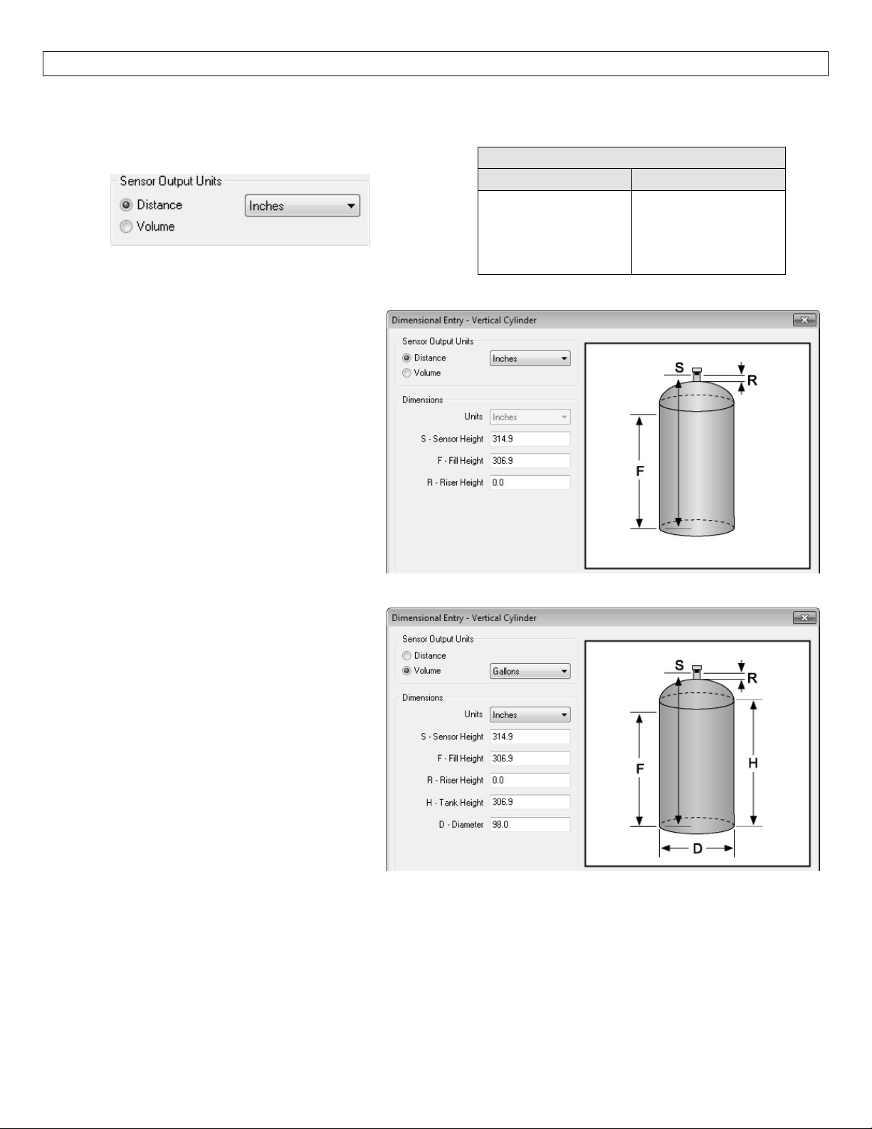
Dimensional Entry – Vertical Cylindrical Example:Choose the Sensor Output Units as Distance or Volume.
AfterchoosingtheSensorOutputUnits,selecttheunitsofmeasurementinthepulldowntotheleft.
UnitsofMeasurement
Distance Volume
Inches
Cm
Feet
Meters
Gallons
Liters
Distance–SensorOutputUnits:
Enter the dimensions of the tank.You must
enterdatainallfieldsshown.
SensorHeight:Distancefromthebottomof
thetanktothebottomofthetransducer.
FillHeight:Distancefrom thebottomof the
tanktothemaximumliquidheight.
RiserHeight:Distancethesensorisrecessed
within ariser,measuredfromthebottom of
thesensortotheinsideofthetank.
Volume–SensorOutputUnits:
Enter the dimensions of the tank.You must
enterdatainallfieldsshown.
SensorHeight:Distancefromthebottomof
thetanktothebottomofthetransducer.
FillHeight:Distancefrom thebottomof the
tanktothemaximumliquidheight.
RiserHeight:Distancethesensorisrecessed
within ariser,measuredfromthebottom of
thesensortotheinsideofthetank.
Tank Height:Distance from the bottom of
thetanktothetopofthestraightsidewall.
Diameter:Distance of the inside tank
diameter.
12
Page 13
GETTINGSTARTED(continued) StepFive
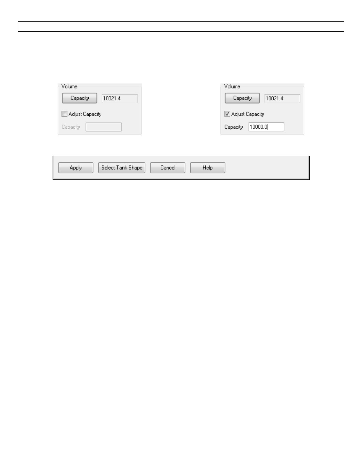
Volume – Tank Capacity:After entering the dimensions, press the Capacity button to show the Calculated
Capacity of the tank.If the Calculated Capacity is slightly different than the expected capacity, click on the
AdjustCapacityboxandentertheexpectedcapacityofthetank.IftheAdjustedCapacityismorethan10%of
theCalculatedCapacity,recheckthedimensionsinformationenteredabove.
Whenalldimensionsareentered,presstheApplybuttontoreturntothepreviousConfigurationwindow.
Apply–TransfersthedimensionstotheoriginalConfigurationwindow.
Tanks–ReturnstothepreviousShapeSelectionwindow.
Cancel–ReturnstotheConfigurationwindowwithoutsavinganyinformation.
Help–JumpstotheHelpmenu.
13
Page 14
GETTINGSTARTED(continued) StepFive
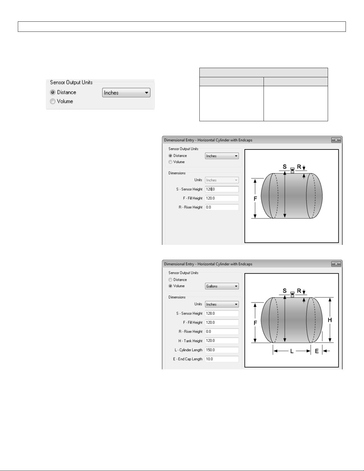
Dimensional Entry – Horizontal Cylindrical with Endcaps Example:Choose the Sensor Output Units as
Distance or Volume.After choosing the Sensor Output Units, select the units of measurement in the pull
downtotheleft.
UnitsofMeasurement
Distance Volume
Inches
Cm
Feet
Meters
Gallons
Liters
Distance–SensorOutputUnits:
Enter the dimensions of the tank.You must
enterdatainallfieldsshown.
SensorHeight:Distancefromthebottomof
thetanktothebottomofthetransducer.
FillHeight:Distancefrom the bottomofthe
tanktothemaximumliquidheight.
RiserHeight:Distancethesensorisrecessed
within a riser, measured from the bottom of
thesensortotheinsideofthetank.
Volume–SensorOutputUnits:
Enter the dimensions of the tank.You must
enterdatainallfieldsshown.
SensorHeight:Distancefromthebottomof
thetanktothebottomofthetransducer.
FillHeight:Distancefrom
thebottom of the
tanktothemaximumliquidheight.
RiserHeight:Distancethesensorisrecessed
within a riser, measured from the bottom of
thesensortotheinsideofthetank.
TankHeight:Distancefromthebottomofthetanktothetopofthestraightsidewall.
CylinderLength:Distanceofthestraightlengthofthetank.
EndCapLength:Distanceofoneendcap.Bothendcapswillbeusedinthevolumecalculation.
14
Page 15
GETTINGSTARTED(continued) StepFive
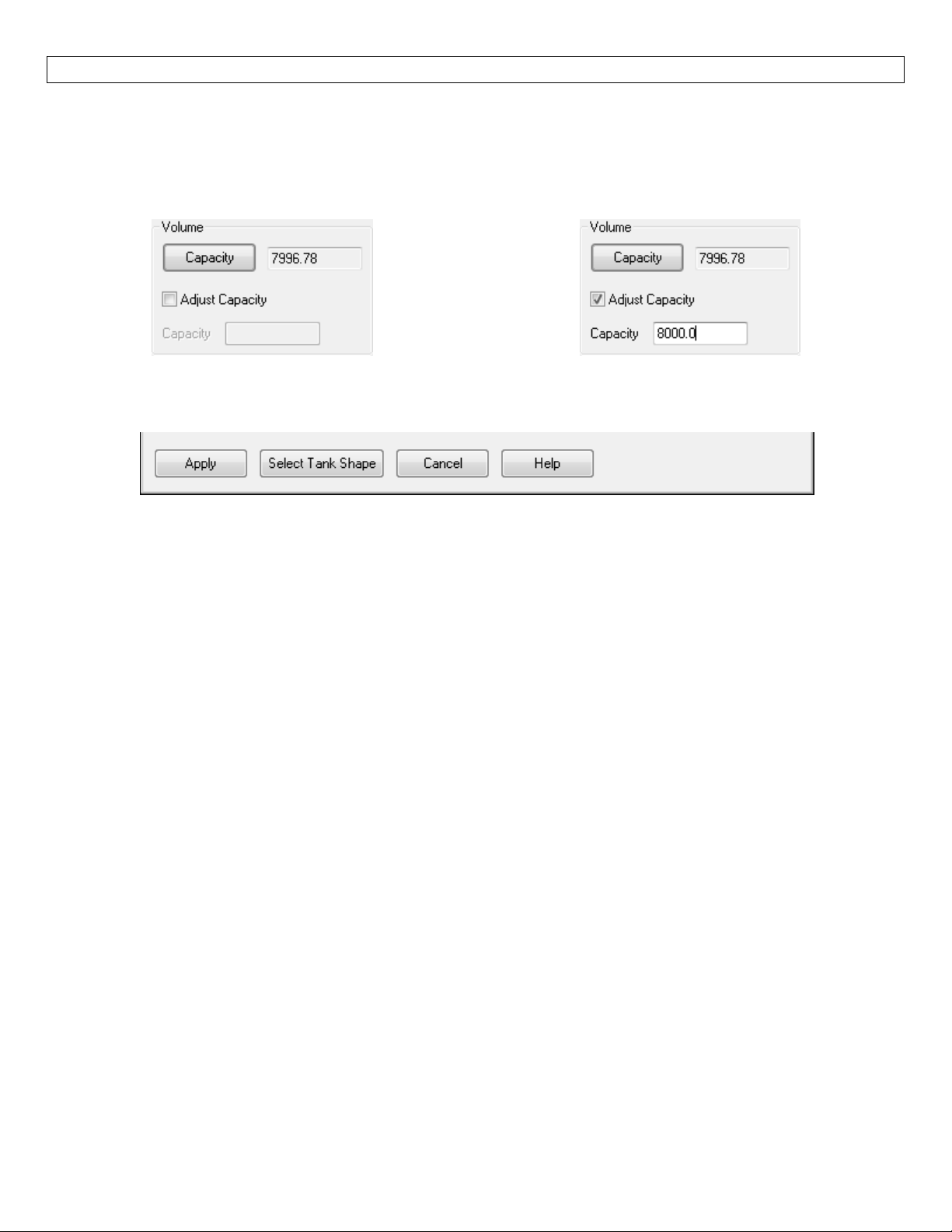
Volume – Tank Capacity:Upon entering the dimensions, press the Capacity button to show the Calculated
Capacity of the tank.If the Calculated Capacity is slightly different than the expected capacity, click on the
AdjustCapacityboxandentertheexpectedcapacityofthetank.IftheAdjustedCapacityismorethan10%of
theCalculatedCapacity,recheckthedimensionsenteredabove.
Whenalldimensionsareenterediscompleted,presstheApplybuttontoreturntothepreviousConfiguration
window.
Apply–TransfersthedimensionsbacktotheoriginalConfigurationwindow.
Tanks–ReturnstothepreviousShapeSelectionwindow.
Cancel–ReturnstotheConfigurationwindowwithoutsavinganyinformation.
Help–JumpstotheHelpmenu.
15
Page 16
GETTINGSTARTED(continued) StepFive
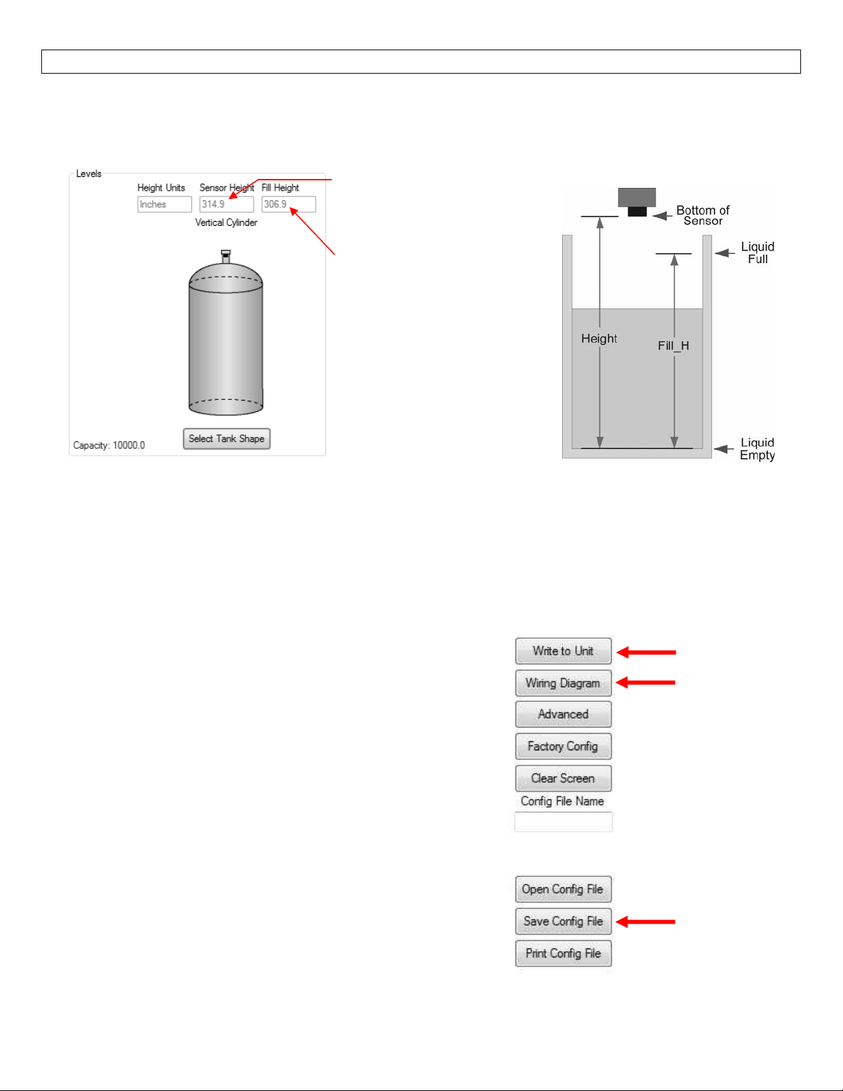
3.LevelConfiguration
Thissectionof thesoftwareis whereyouenter applicationmeasurement values.Allvaluesmust befilledin
beforemovingtothenextstep.
Sensor Height: Distance from
thebottomofthe tanktothe
bottomofthetransducer.
Fill Height: Distance from the
bottom of the tank to the
maximumliquidheight.
Note: If Volume is selected,
Sensor Height and Fill Height
are grayed out and can only
be changed on the
DimensionalEntryPage.Also,
the Capacity of the tank will
be shown in the lower left
corner.
4.WritetoUnit
Afteryouhaveenteredconfiguration, tankshapeinformationandlevel values,click“WritetoUnit”toload
theconfigurationintothememoryofthesensor.Whencompleted,thisconfigurationwi ll remaininsidethe
sensor’smemoryandwill not change unlessthesensor isconnectedto LVCN‐414‐SW software and anew
configurationiswrittentothesensor.Lossofpowerwillnotchangeorlosetheconfigurationwithinsensor
memory.
Next, use the file management features to save your
configurationbyclicking“SaveConfig File”and printyourwiring
diagrambyclicking“WiringDiagram.”
“SaveConfig File”will savethis configurationas atext filewhich
can be loaded back into the LVCN‐414‐SW
the “Open Config File” button.It is good practice to save the
configuration file for each different configuration with a unique
nameforeasyidentification.Ifusingmultiplesensorsinidentical
applications, then use of a single configuration file is
recommended.
“Wiring Diagram” will display a PDF file showing the unique
wiring for the specific configuration created.The PDF can be
printedorEmailed.Itisgoodpracticetosavethewiringdiagram
asabackup.
software by pressing
WritetoUnit
Wiringdiagram
SaveConfigFile
16
Page 17
WIRING StepSix
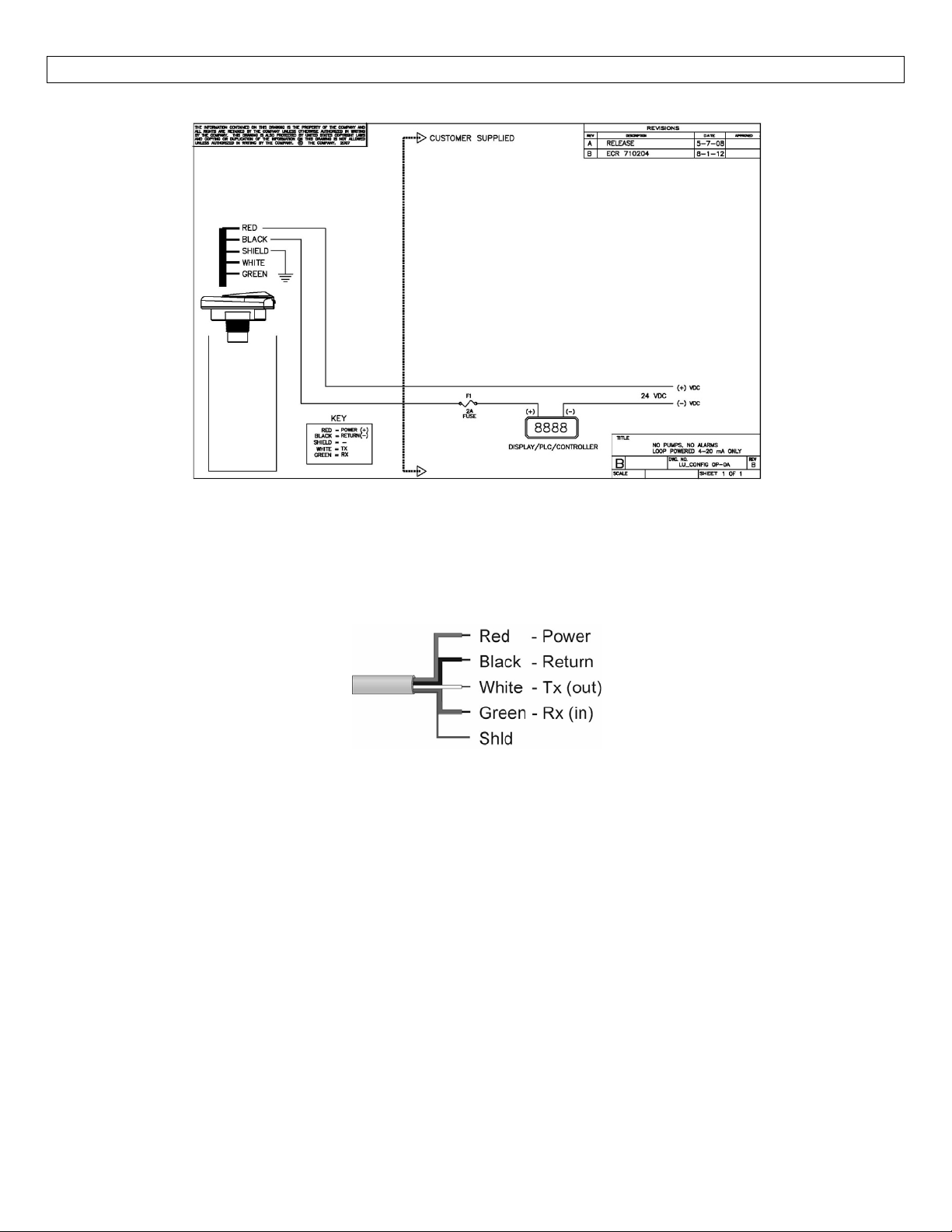
WiringDiagram
WiringLVU2700Series
After you have finished positioning and mounting LVU2700 Series, follow the software’s wiring diagram to
wireLVU2700 Series.OmegaEngineeringrecommendsusingaqualifiedlicensedelectricianto wireLVU2700
Seriesandyourapplication’scomponents.
WireConnections:
Red&Black
RedandBlackleadsareforconnectiontoa 24
andblackwirescanbeextendedupto1,000feetusinga22gaugeorlargerwire;howeverdonotextendthe
greenandwhitewires.
White&Green
WhiteandGreen leads arereservedfor use withthesoftware and shouldnotbeconnected during usagein
theapplication.Thesewires should notbeconnected totheLVCN414‐SW while powerissupplied from any
sourceotherthantheLVCN414‐USBseriesFob.
VDCpowersupplyortoa4‐20mAlooppowersource.Thered
Note: Once the LVU2700 Series is configured, isolate the white and green wires from active power to
preventashortoftheconfigurationcircuit.
Note:DonotextendtheWhite&Greenwiresbeyond15’.
17
Page 18
WIRING(continued) StepSix
Generalnotesforelectricalconnections,usageandsafety:
Where personal safety or significant property damage can occur due to a spill, the installation must
havearedundantbackupsafetysysteminstalled.
Wiringshouldalwaysbecompletedbyalicensedelectrician.
Supplyvoltageshouldneverexceed28VDC.
Thesensormaterialsmustbechemicallycompatiblewiththeliquidstobemeasured.
Designafail‐safesystemforpossiblesensorand/orpowerfailure.
NeverusethesensorinenvironmentsclassifiedasHazardous.
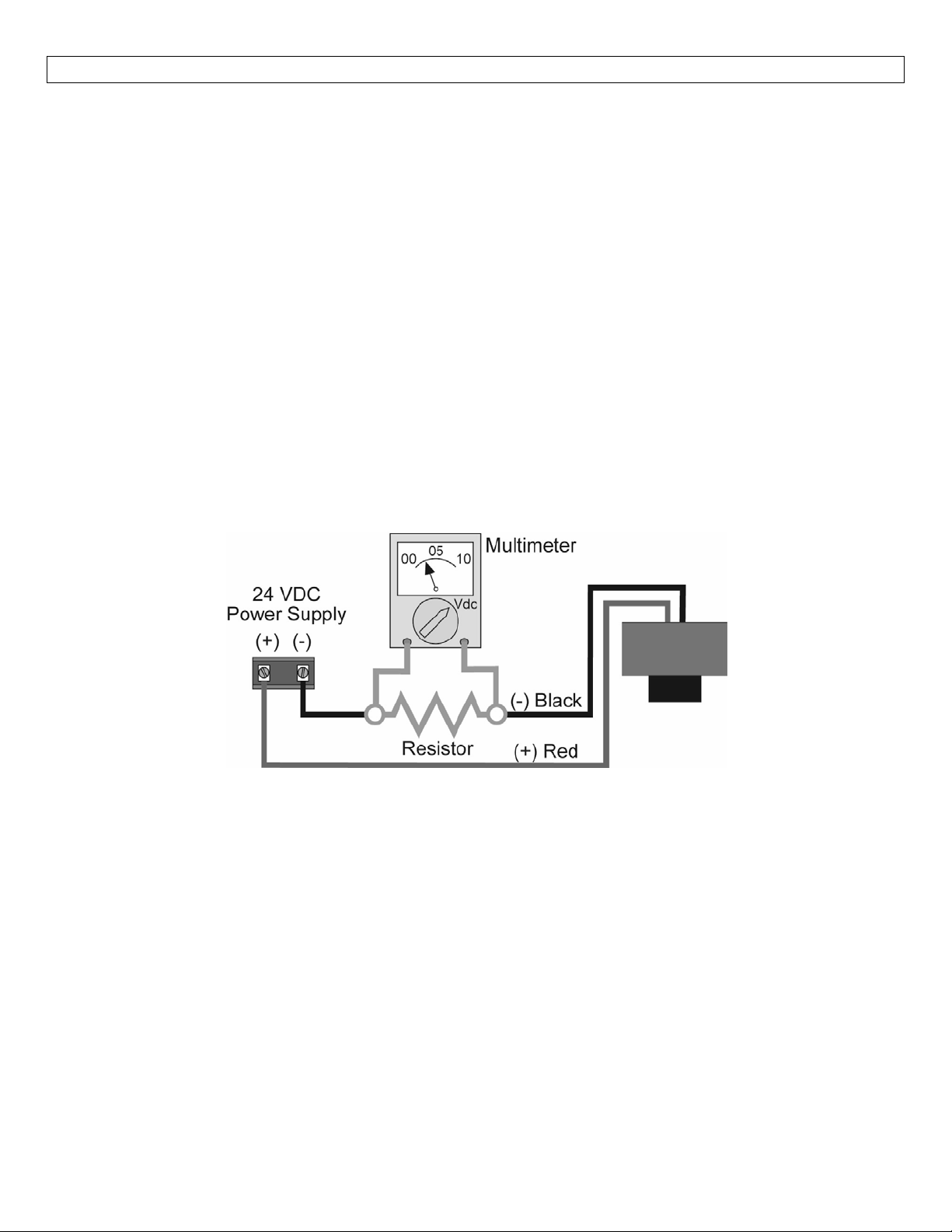
VoltageOutput
LVU2700Seriescanbeused asa0to5 or0to10VDC outputdevice.Aresistorwillneedtobeaddedtothe
circuittoenableavoltageoutput(refertothewiringdiagrambelow).
0‐5VDCoutput
o Adda250Ohmresistor
o Actualoutputwillbe0.8to5VDC
0‐10VDCoutput
o Adda500Ohmresistor
o Actualoutputwillbe2to10VDC
18
Page 19
WIRING(continued) StepSix
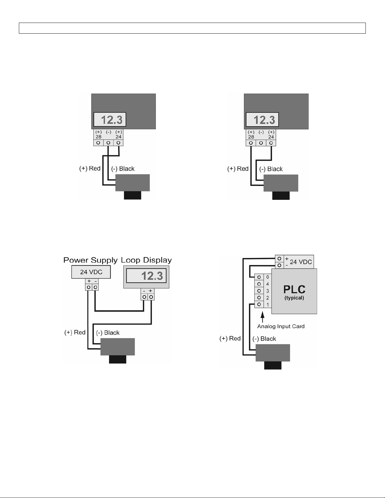
WiringtoDisplay,Controllers&PLC’s(continued)
ProportionalLevelController
LVCN‐51Series
JWAmode(FactorySetting)
GenericLoop
PoweredDisplay
ProportionalLevelController
LVCN‐51Series
JWBmode
GenericPLC
19
Page 20
INSTALLATION StepSeven
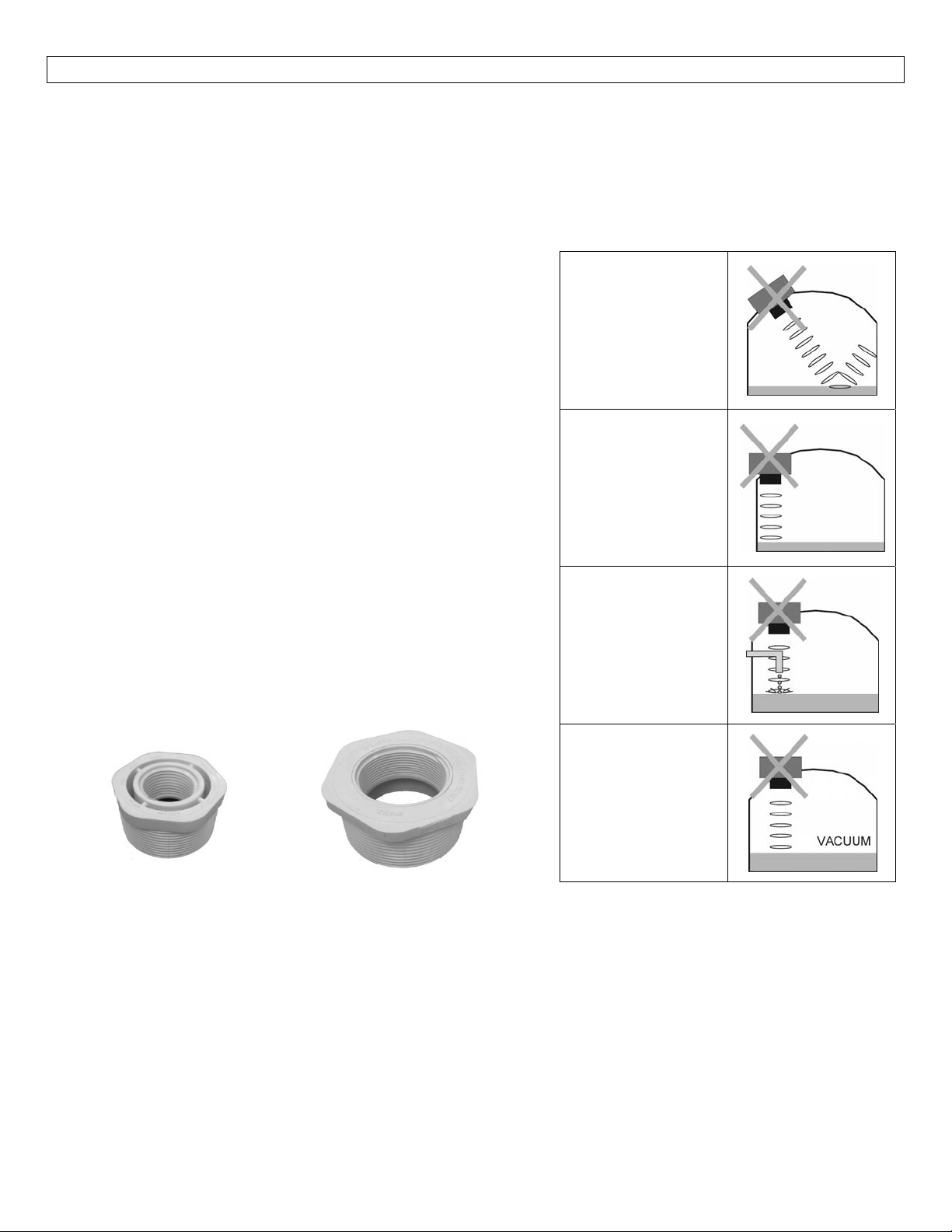
The LVU2700 Series should always be mounted perpendicular to the liquid surface and installed using the
providedFKMmountinggasket.Makesurethatthefittingandtransmitterthreadsarenotdamagedorworn.
Always hand‐tighten the transmitter within the fitting.Perform an installed leak test under normal process
conditionspriortosystemstartup.Note:ThepreferredmountingfittingfortheLVU2710seriesisaplastic(2”
threadx1”thread)reducerbushing.
MountingGuide
1. Donotmountatanangle
2. Liquidshouldneverenterthedeadband
3. SideWall:
a. ForLVU2710Series‐mountatleast2”fromtheside
wall
b. For LVU2718,LVU2726 &LVU2732 Series‐mountat
least3”fromthesidewall
Donotinstallat
anglerelativeto
theliquid.
4. Donotmountwhereobstacleswillintrudeonsensor’s
beamwidth
a. LVU2710Series‐mountatleast2”fromobstacles
b. ForLVU2718,LVU2726&LVU2732Series‐mountat
least3”fromobstacles
5. Donotmountinavacuum
Donotinstall
within3”oftank
sidewall.
6. Avoidmountinginthecenterofadometoptank.
7. Inconebottomtank,positionthesensoroverthe
deepestpartofthetank.
Donotinstallwith
Installationinexistingfittings:Iftheexistingfittingislarger
than the threads of the sensor, select a reducer bushing
objectsinthe
beam.
suchastheLVU800‐2N40(2”threadx1”thread)orLVU800‐
3N40(3”threadx2”thread).
Donotinstallin
applicationswith
vacuum.
LVU800‐2N40
LVU800‐3N40
MetalTanks(LVU2710series)
OmegaEngineeringultrasonictransmittershavebeenoptimizedforuseinnon‐metallicfittings.
1. Forbestperformance,avoidtheuseofmetallicfittings.
a. Useaplastic 2”x 1”reducerbushing(suchasLVU800‐2N40)or aplastic 1”tankadapter(such
asLVU800‐1B).
2. While installations directly into a 1” metal fitting are not recommend
ed, acceptable results may be
obtained if the 1” fitting is a half coupling in form and the outer diameter of the coupling is tightly
wrappedinvinyltapetodampenvibrations.
20
Page 21
INSTALLATION(continued) StepSeven
Fitting Selection: Check the part number to determine the required fitting mount size and thread type.
LVU2700Seriesiscommonlyinstalledintankadapters,flanges,bracketsorstandpipes.Note: Alwaysinclude
thegasketwheninstallingtheLVU2700Series.
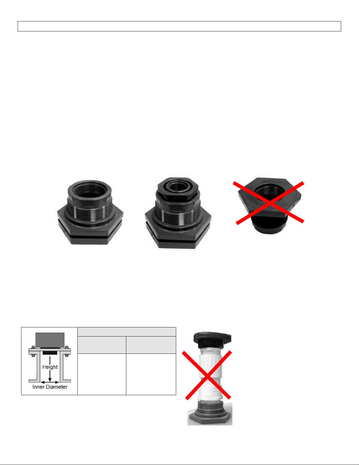
1. TankAdapter:Select atankadapterfitting,1”orlargerforthe LVU2710seriesor2”orlargerforthe
LVU2718,LVU2726&LVU2732series.
a. ForbestresultswiththeLVU2710Series,selecta2”tankadapter(LVU800‐2B)andaddaplastic
2”by1”reducerbushing(LVU800‐2N80).
b. Avoid tank adapter (thread x thread) styles and/or pipe stops forward of the installed
transducer.
c. Alwaysmountthetankadaptersothemajorityoffittingisoutsidethetank.
i. Nevermountthetankadapterupsidedownorthebulkofthematerialisinsidethetank.
2”TankAdapter
SocketxThread
(LVU800‐2Bshown)
2. Riser:Installationswithtall,narrowriserscanimpedetheacousticsignal.
a. Core Out Concrete:Applications where tank with a concrete ceiling that has been cored out
canalsobeconsideredasarisertypeapplication.Inthes
DiametertoCoreHeight)forthediameterofthecore.
a. LVU2718, LVU2726 & LVU2732 Series: 2” (5 cm) diameter risers should be no taller than 5”
(12.7cm).Largerdiameterrisersshouldbenotallerthan12”(30.5cm).
b. LVU2710Series:
TankAdapter(LVU800‐2B)
w/2”x1”ReducerBushing
(LVU800‐2N80shown)
TankAdapter
ThreadxThread
Donotusethreadxthre
eapplicationsfollowa2:1ratio(Inner
ad
RiserSpecifications
Inner
Diameter
2”(5cm)
4”(10cm)
6”(15cm)
Note:Donotexceedthedimensionslistedabove.
Maximum
Height
3”(7.6cm)
8”(20cm)
12”(30cm)
21
Note: If attempting to raise the
sensorabovethetopofthetank
toallowforahigherfillcapacity,
avoid theuseoftalland narrow
risers.The example to the left
exceeds the dimensions listed in
the Riser Specifications chart.
Use alargertankadapter which
takes into account the Riser
Specifications.
Page 22
INSTALLATION(continued) StepSeven
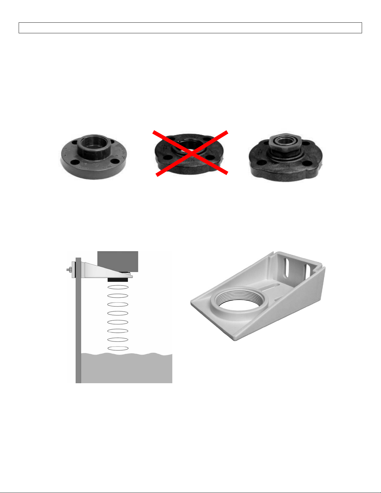
3. Flange(LVU2710series):Ifinstallingonaflange, selectaflangewitha threadthatisabovethe plane
oftheflange.
a. TheLVU2718,LVU2726&LVU2732seriesworkswellwithFlangeinstallations.
b. Avoid theuse ofblind flangeswith tappedthreads orflanges wherethe threadsare evenwith
theplaneoftheflange,suchastheBanjo1"PolyANSIFlange(seriesAF100).
c. Useaflangewitha2”threadandadda2”to1”reducerbushingtocompletetheinstallation.
2”Flangew/
threadoutofplane
(LVU800‐2Fshown)
Donotusethreadinplane
4. Side Mount Bracket: For installations in open tanks and sumps, use the LVM‐30 series side mount
bracket.
a. FortheLVU2710 series,order theLVM‐31sidemountbracket, whichincludes aplastic2”x1”
Reducerbushing.
b. FortheLVU2718,LVU2726&LVU2732,series,ordertheLVM‐30sidemountbracket.
2”Flangew/
threadinplane
2”Flangew/
ReducerBushing
(LVU800‐2N80shown)
22
LVM‐30SeriesShown
Page 23
INSTALLATION(continued) StepSeven
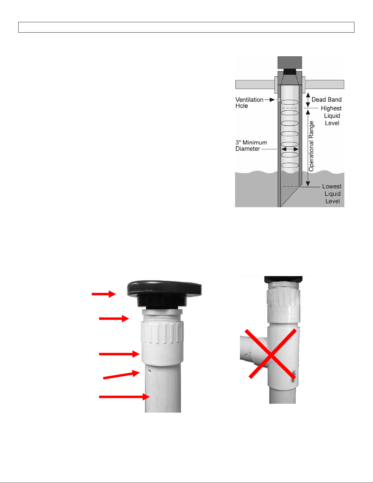
5. Stand Pipe:A standpipe maybe used to dampen turbulence or when foam is present in the
application.
a. Pipecanbemadeofanymaterial.
b. Selectaminimum3”IDpipeforthestandpipe.
i. A 2”pipeisusable with the LVU2710 series,butit
istheminimumdiameterpipe.
ii. Pipeslargerthan3”canalsobeused.
c. UseacouplingorTankAdapterandreducerbushingto
attachtheLVU2700Seriestothepipe.
i. With the LVU2710 series,
reducing bushing such as 2” Thread x 1” Thread
fitting (ex: LVU800‐2N80) or 2” Slip x 1” Thre
fitting(ex:LVU800‐2S80).
ii. With the LVU2718, LVU2726 or LVCN2732 series,
use a reducer bushing such as (3” Thread x 2”
Thread) fitting (ex: LVU800‐3N80) or (3” Slip x 2”
Thread)fitting(ex:LVU800‐3S80).
d. Thepipelengthshouldrunthemeasurementspanand
thebottomofthepipeshouldremainsubmergedatall
timestopreventfoamfromenteringthepipe.
e. Cut a 45° notch at the bottom of the pipe and drill a
1/4”pressureequalizationholeinthedeadband.
f. Thepumpsshouldnotdriveliquidpasttheopenendof
the stand pipe which causes the liquid in the pipe to
oscillate.
LVU2710
Series
2”(T)x1”(T)
ReducerBushing
(LVU800‐2N40)
2”(SxT)
Coupling
VentHole(1/4”)
2”PVCPipe
LVU2710attachedtoaLLVU800‐
2N40(2”x1”reducerbushing)to
be sure to use a plastic
aSxT2”Coupling.
ad
Avoidtheuseofateewithinthe
standpipe.Ateecancreate
signalswhichwillinterferewith
thesensor’sperformance.
false
23
Page 24
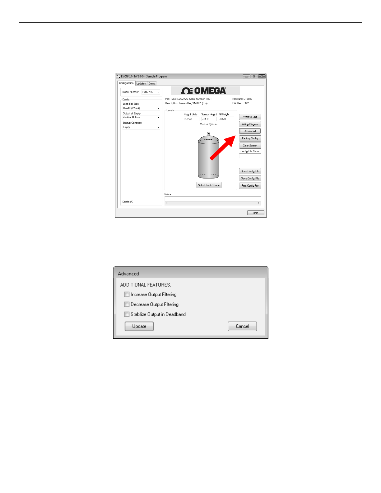
ADVANCEDFEATURES StepEight
This tool is designed to help solve operational issues.Changing these setting will alter the performance of
your unit. Please read through this HELP file to assist you in making adjustments or if still unclear about a
specificissue,pleasecontactOMEGAENGINEERING,ApplicationsEngineering.
AboveScreenCaptureisfortheLVU2726series.
NOTE:When the Advanced Button is highlighted with a RED border, this indicates you have selected an
advancedfeature…
Increaseoutputfiltering:Placingacheckmarkintheboxwillincreasethefiltering(averaging)ofthe
analogoutput.Ifyourequirethe4to20mAoutputtobes
ChannelFlowmeasurement,youmightcheckthisbox.
DecreaseOutputFiltering:Placingacheckmarkintheboxwilleliminateallfiltering(averaging)ofthe
analogoutput.Enablesapulsebypulselevelreading.Usethisfiltertoseechangesinlevelafterevery
soundpulse.
moothfortheapplicationsuchasOpen
Note:Nevercheckincreaseoutputfilteringanddecreaseoutputfilteringatthesametime.
StabilizeOutputinDeadband:Placingacheckmarkintheboxwillactivateafiltertoholdtheoutput
atFullifthelevelentersthedeadbandoftheTransmitter.
deadbandatasmoothandsteadyrate.
24
Thisfilterrequirestheleveltoleavethe
Page 25
APPENDIX StepNine
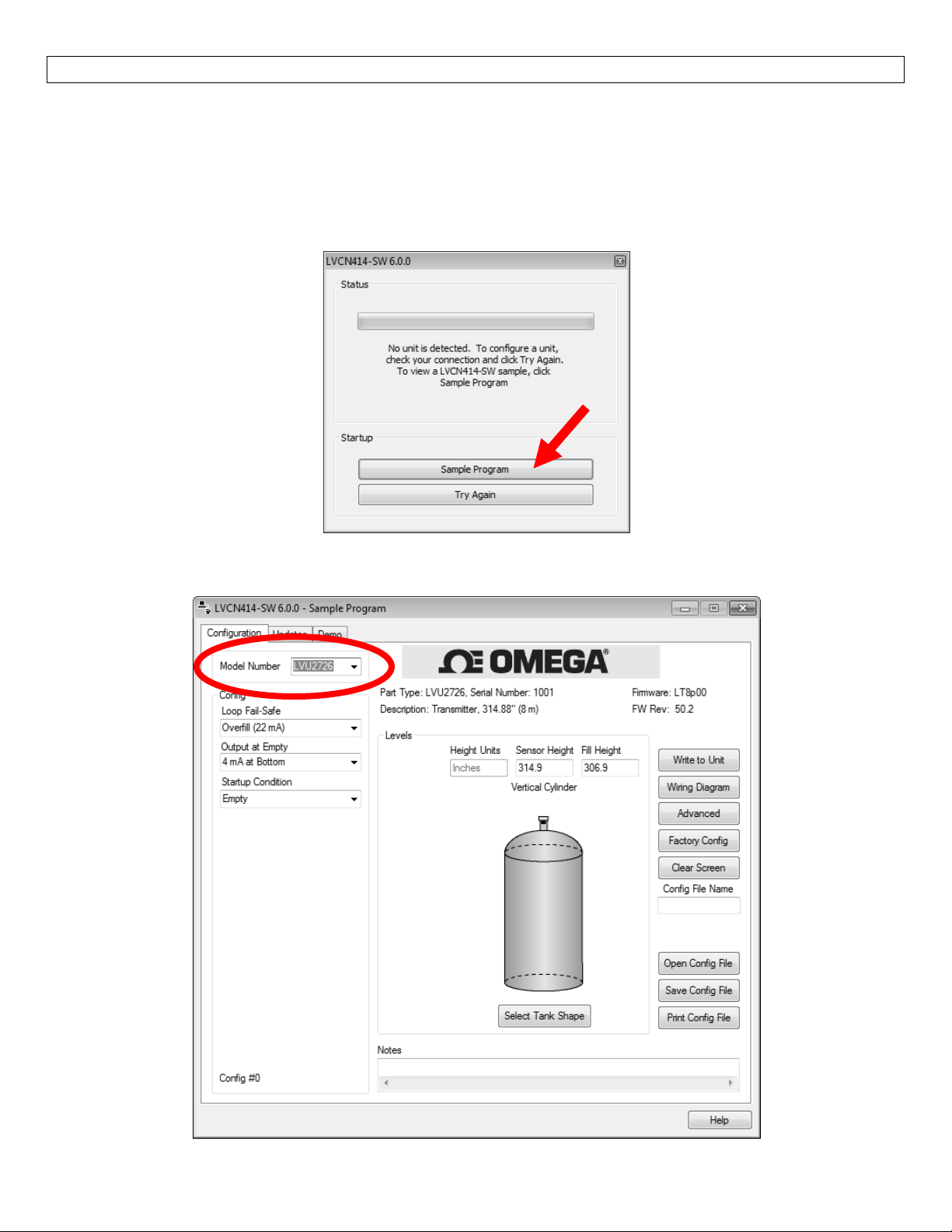
SampleProgram:AsampleversionoftheLVCN‐414‐SWsoftwareisavailableanytimeasensorisnotattached
to thesoftware.TheSampleProgramshows all the features intheConfigurationTabof the software.Any
configurationcanbeopened(OpenConfigFile),Saved(SaveConfigFile)orPrinted(PrintConfigFile)withthe
SampleProgram.SampleProgramcannotbeviewedifasensorisattachedtothecomputerviatheUSB®Fob.
ToviewtheSampleProgram,starttheLVCN‐414‐SWsoftwarewhenasensorisnotattachedtothecomputer.
Attheopeningscreen,selectSampleProgram.
Selectyour modeltype inthe upperright‐hand corner.Note:When savingor openi
suretheModelNumbermatchesthesensorsyouintendtouse.
nga configuration,make
25
Page 26
APPENDIX StepNine
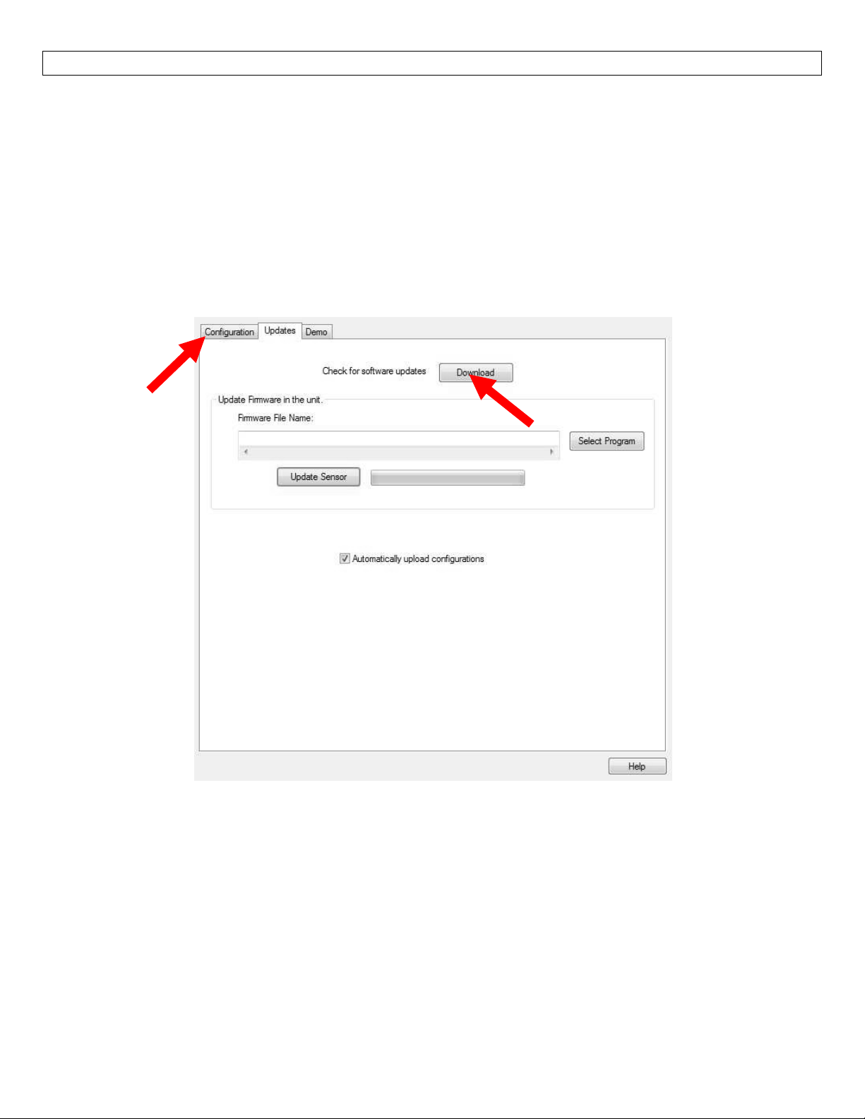
UpdatingLVCN414‐SWSoftware
Thesoftwarecanbeupdateddirectlywithinthesoftware.SimplyclickontheUpdatesTabatthetopofthe
windowandpresstheDownloadbutton.MakesurethatyourcomputerhasaccesstotheInternet.Ifnot,an
errorwindowwillappear.
WhentheDownloadbuttonispressed,thesoftwarewillchecktheversionofsoftwa
mostrecentversionatOmegaEngineering.Iftheversionsaresimilar,awindowindicatingthatthemost
recentversionisinstalled.Ifnot,thenawindowwillappearaskingtodownloadthelatestversion.Followthe
instructionsforinstallingthelatestversion.
reyouareusingwiththe
26
Page 27
APPENDIX(continued) StepNine
UpdatingTransmitterFirmware
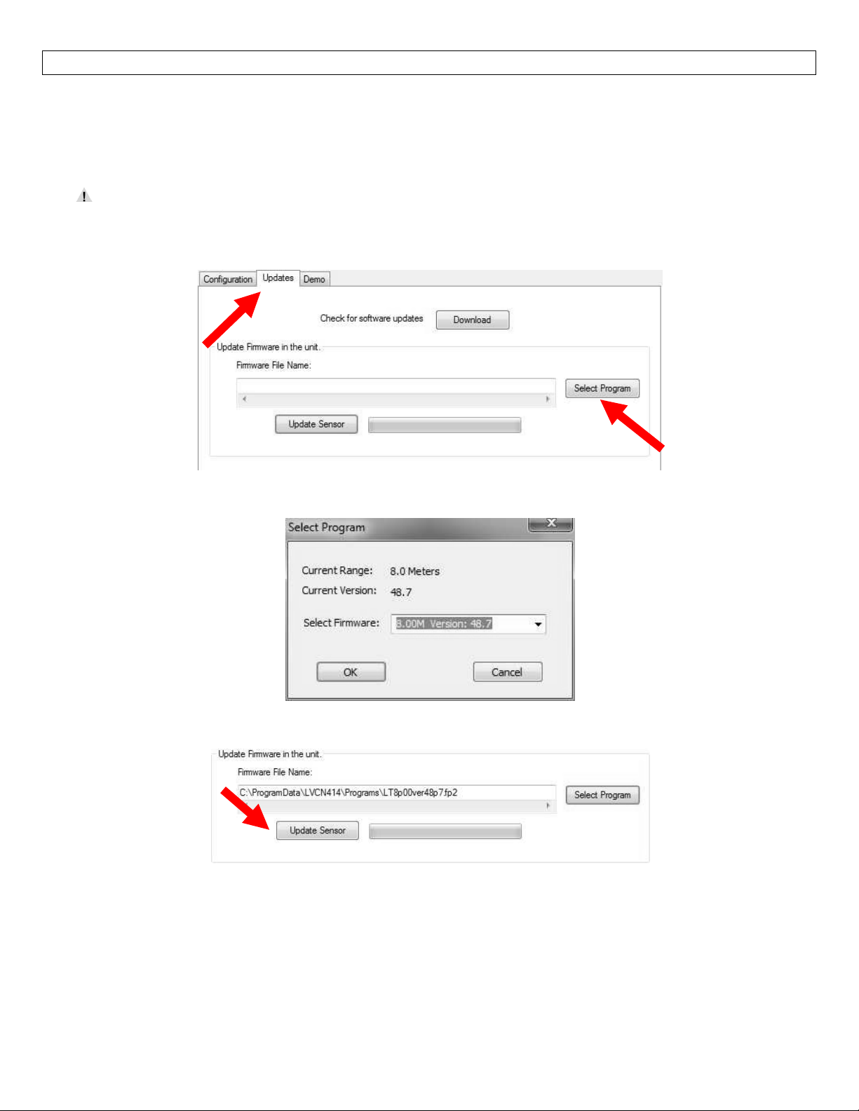
The software can also be used to update the firmware inside the LVU2700 Series transmitter.This feature
allowsthetransmittertobeupdatedwhennewfeaturesareadded.FirstopenLVCN414‐SWsoftwarewithan
LVU2700SeriestransmitterconnectedandthelatestversionofthesoftwaredownloadedtoyourPC.
Whenupdatingthesensorfirmware,disconnectthesensorfromallotherdevicesincludingdisplays,
controllers, power supplies, PLC’s, pumps, valves and alarms.Connect the devices back after the
firmwarehasbeenupdated.
ClickontheUpdatesTabandthenclickonSelectProgramtoselecttheFirmwareupdate.
SelectthelatestversionofthefirmwarefileandclickonOK.
ConfirmthattheaddressiscorrectandthenclickonUpdateSensortobeginthefirmwareupdate.Thisstep
shouldtakelessthan1minute.YoucanfollowtheprogresswiththestatusbartotherightoftheUpdate
Sensorbutton.Whencompleted,clickontheConfigurationtabtoconfigurethetransmitter.Remember,
whenthefirmwarehasbeenupdated,theunitwillreturntoitsoriginalfactorysettings.
Ifthereisacommunicationinterruptionduringtheupdate,theprocesswillstop.ItisOKtoclickon
UpdateSensoragaintostarttheprocessoveragain.
27
Page 28
APPENDIX(continued) StepNine
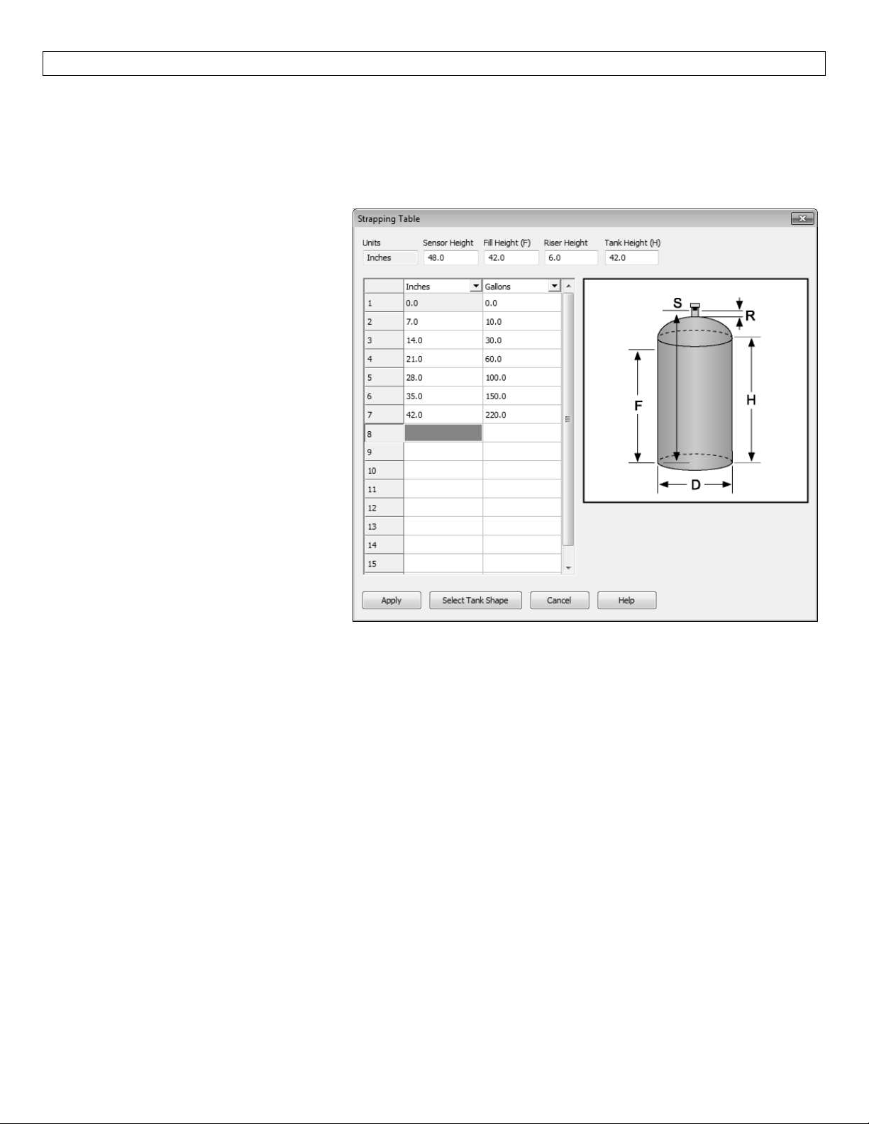
StrappingTable:LVCN‐414‐SWSoftwarefeaturesastrappingtablethatenablesyoutoenterupto16custom
referencepointsinsteadofusingthestandardtankshapes.Thisfeatureisidealforoddshapedtanksortanks
wherespecificlevelsareknownvolumesofliquid.
ToaccesstheStrappingTable,clickonStrappingTablein
Enter the Sensor Height, Fill Height,
Riser Height and Tank Height.This
information is used to configure the
sensortothetank.
The Strapping Table also has two
columnsof16pointsforenteringthe
knowntankdata.
Selectthedimensionsand/orvolume
at the top of the two columns
enterthetankdata.
When done, press “Apply” to
transfer the data and return to the
Configurationwindow.
and
theShapeSelectionWindowandpress“OK”.
28
Page 29
APPENDIX(continued) StepNine
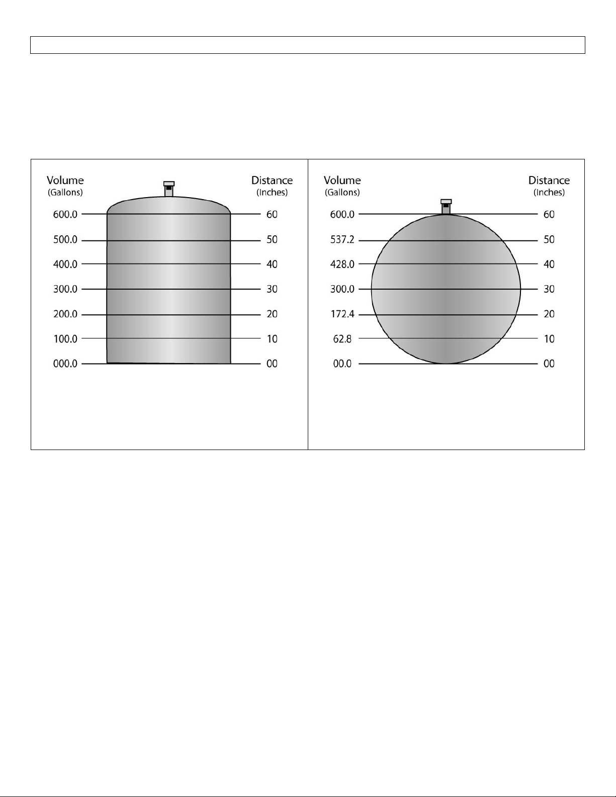
Linearvs.Non‐Linear:Twooftheshapes(VerticalCylinderTank andRectangularTank)willalwaysprovidea
linearoutput,regardless of selectingDistance or Volume.Theremainingfour shapes(VerticalCylinder Tank
withConeBottom,HorizontalCylinder TankwithEndCaps,Horizontal CylinderTankwithSphericalEnd Caps
andSphericalTank)willhavealinearoutputwhenDistanceisselected,butwillhaveanon‐linearoutputwhen
volumeisselected.
VerticalCylindricalTank
In the above illustration, 10”of liquid will always
beequalto100gallonsofliquid(1”=10gallons).
HorizontalCylinderTankwithEndCaps
In the above illustration, 10” of liquid does not
equal 100 gallons.The 10” at the bottom
representsariseof62.8gallonswherethechange
between 10” and 20” represents an increase of
109.6gallons.
Whenvolumeisselected,the4‐20mAoutputfromthesensorwillbeproportionaltothevolumeofthetank,
nottheheightofthetank.Thismeansthatthecurrentoutputwilltrackthevolumeofthetank(ingallonsor
liters) within a non‐linear tank (Vertical Cylinder Tank with Cone Bottom, Horizontal Cylinde
Caps,HorizontalCylinderTankwithSphericalEndCapsorSphericalTank).
Whenconnectingthesignaloutputtoadisplay,thesignalwill followthevolume ofthetank.Thedisplaywill
alsoreflectthevolumeofthetankandnottheheightoftheliquid.
Example#1(VolumeOutput):intheaboveillustrations,@ 20”ofliquid,thedisplaywillshow200.0gallonsin
theVerticalCylindrical Tank.However, in theHorizontalCylinder Tank withEndCaps, the samelevelof20”
wouldshow172.4gallons.
r Tank with End
29
Page 30
APPENDIX(continued) StepNine
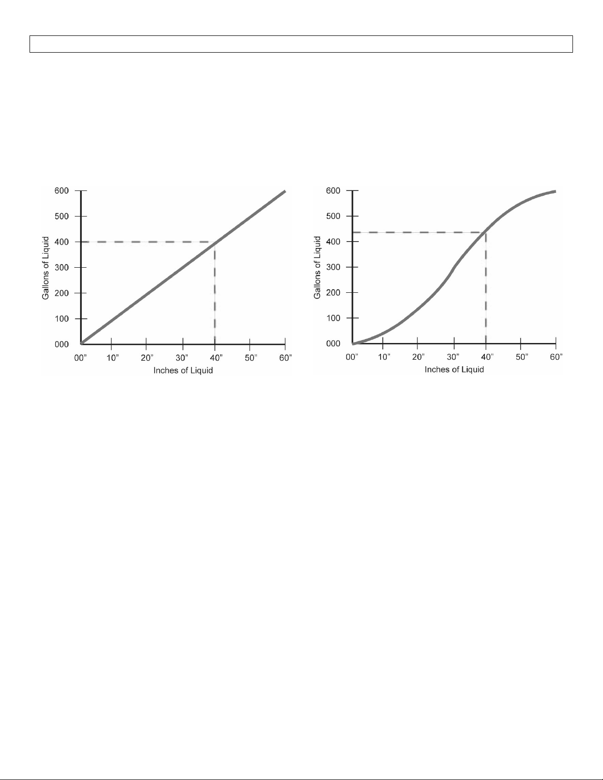
Example #2 (Current Output):In the illustrations on the previous page, the 4mA signal is set at 0” (0.0
gallons)andthe 20 mAsignalis setto60” (600.0gallons).IntheVertical CylindricalTank,40” of liquidwill
outputacurrent signalof14.67mA.However, intheHorizontal CylindricalTankwith EndCaps,40” ofliquid
will output a current signal of 15.41mA.A simple loop display set with 4mA = 0 gallons and 20 mA = 600
gallons will show two different volumes based upon the tank shape configuration.Vertical Cylindrical Tank
willshow400.0gallonswhileHorizontalCylindricalTankwithEndCapswillshow428.0gallons.
VerticalCylindricalTank
In the above illustration, 10”of liquid will always
beequalto100gallonsofliquid(1”=10gallons).
HorizontalCylinderTankwithEndCaps
In the above illustration, 1” of liquid does not
equal 10 gallons.The 10” at the bottom
representsariseof62.8gallonswherethechange
between 10” and 20” represents an increase of
109.6gallons.
30
Page 31
APPENDIX(continued) StepNine
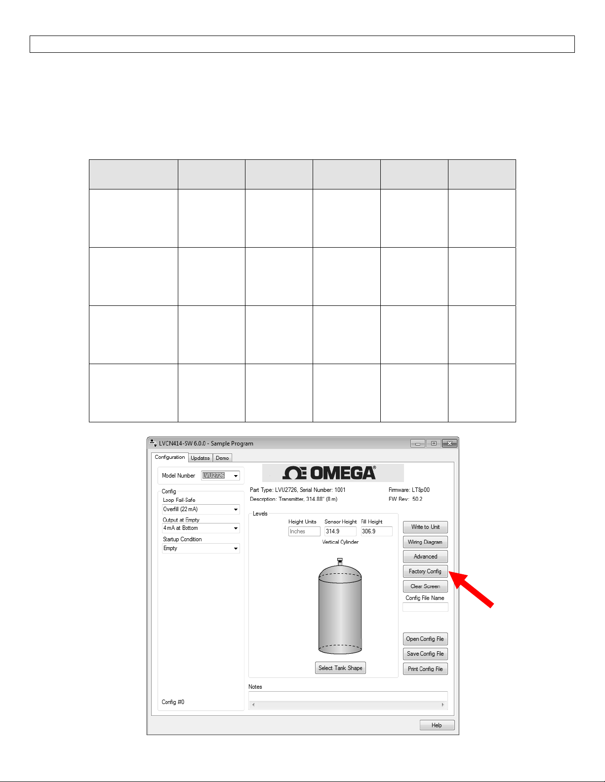
FactoryDefault
PressingtheFactoryConfigbuttonintheConfigurationmenuwillreturnthescreentothefollowingsettings.
Outofthebox,theLVU2700Serieswilloutputa4‐20mAoutputthatismaximizedforitsoperationalrange.
ThetransmittercanbeusedintheoriginalfactorysettingwithoutconfigurationwiththeLVCN4141‐SW
Software.Usethetablebelowtoidentifytheconfigurationofthesensoroutofthebox.
FactoryDefaultsTable
Part
Number
LVU2710
LVU2710‐B
LVU2710‐G
LVU2710‐G‐B
LVU2718
LVU2718‐B
LVU2718‐G
LVU2718‐G‐B
LVU2726
LVU2726‐B
LVU2726‐G
LVU2726‐G‐B
LVU2732
LVU2732‐B
LVU2732‐G
LVU2732‐G‐B
Sensor
Height
118.1”
(300cm)
216.5”
(550cm)
314.9”
(800cm)
393.7”
(1000cm)
Fill
Height
114.1”
(290cm)
530cm
(208.7”)
306.9”
(780cm)
385.8”
(980cm)
Loop
Fail‐Safe
Overfill
(22mA)
Overfill
(22mA)
Overfill
(22mA)
Overfill
(22mA)
Output
atEmpty
4mA@
Bottom
4mA@
Bottom
4mA@
Bottom
4mA@
Bottom
Startup
Condition
Empty
Empty
Empty
Empty
31
Page 32
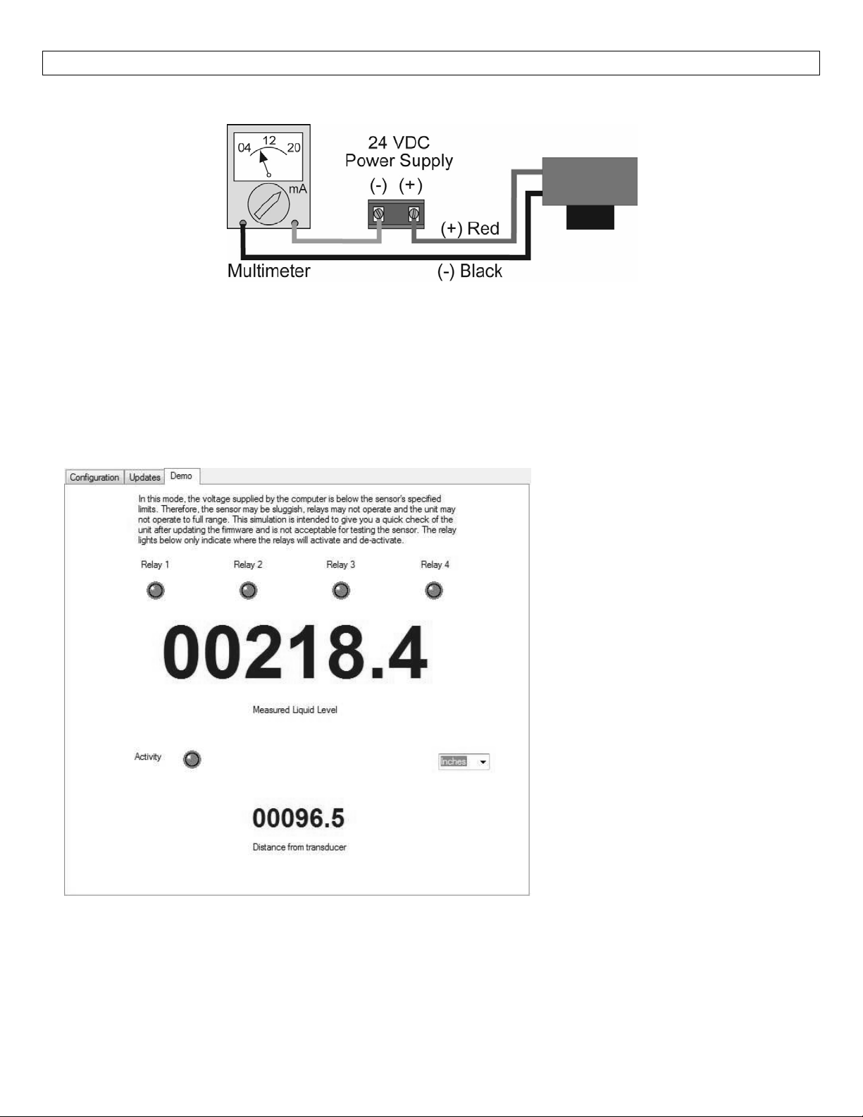
APPENDIX(continued) StepNine
TestingtheTransmitter
1. Connectamultimeterinserieswiththeblackwiretoreadthecurrentoutput.
2. Verifythatthecurrentincreases(tankfilling)anddecreases(tankemptying)appropriatelyinthe
calibratedspan.
3. Ifnot,carefullyobserveandattempttocorrelateanyinstallation,levelorapplicationeventformore
specifictroubleshootingdirection.
DemoPage
ToviewtheDemopage(shownhere),clicktheDemotabonthetopofthescreen.
The demo page is a simulation,
useful for verifying the
configuration.There is not
enoughpowergoingtotheunitto
power the relays in the Demo
mode.The larger numbers
represent the liquid level while
the smaller numbers show the
distance from the transducer to
thesurface.
The senor must be pointed at a
flatperpendicularsurfacewhilein
the Demo mode.If not, the
displaywillreadLOST.
If the display reads EMPTY,
thenthetargetisfurtheraway
from the sensor than the
SensorHeightsetting.
Ifthedisplayreads FULL, then
the target is closer to the
sensor than the Fill‐Height
setting.
32
Page 33

APPENDIX(continued) StepNine
Troubleshooting
PROBLEM SOLUTION
Transmitterindicatesa
currentof0mA
Transmitterjumpstoa
currentreadingbetween
19and20mA
Transmitterindicatesa
currentover23mA
Transmitteralwaysjumps
toLOSTcondition
Outputoftransmitteris
oppositeofthelevelof
liquid
NoUnitDetectedin
WebCal
Interneterror.Theserver
nameoraddresscouldnot
beresolved.
Checkthewiringforanopencircuit.Anopencircuitisthemost
commonissuewitha0mAsignal
Check the installation of the transmitter.Bad installation
fittings will cause false signals near the top of the tank, which
typicallytranslatestoasignalbetween19and20mA.Alsolook
forinterferencejustbelowthetransmitter.Ifthetransmitteris
installedinametalfitting,switchtoaplasticfitting.
Immediatelycheckthewiring for a shortcircuit.TheLVU2700
Series is current limited to 22 mA.Anything above 23 mA
indicatesashortcircuit.
Check the dimensional configuration (Heightand Fill‐H) of the
LVU2700Series.Makesurethat the Fill‐Hsettingcorresponds
to the full level of liquid (from the bottom up) and not the
distancefromthetransmittertotheliquid(topdown).
Check the Output at Empty Setting.Make sure the setting is
correct(4mAatbottomor20mAatbottom).
LVCN414‐SW software cannot detect an LVU2700 Series
connectedtothecomputer.
CheckthattheFobisconnectedtotheUSBport.
Checkthatallfour wires (Red, Black,WhiteandGreen) are
securelyattachedtotheFob.
Checkin DeviceManager thatbothdrivers(Configuration &
EchoFob)arepresent.
This is a warning indicating the computer configuring the
transmitter is not connected to the internet.Click OK to
continue.OmegaEngineeringrecommendsbeingconnectingto
theinternetfor all configurations.Notbeingconnected to the
internet will not prevent the LVU2700 Series from being
configured.
Toturnoffthiswarning,gototheUpdatesTabandclickonthe
check box “Automatically upload configurations”.Click onNO
in the new window and the previous check box will become
unchecked.WebCal™willno longerattempt toconnectto the
internet.Clickingonthecheckboxwillrestorethisfeature.
Cannotaccesssomeofthe
featuresinConfiguration
As choices are made in Configuration, WebCal will begin to
eliminate functions that are no longer active.To reset
Configurationorgetaccesstoallthefeatures,clickontheClear
Screenbutton.
33
Page 34
APPENDIX(continued) StepNine
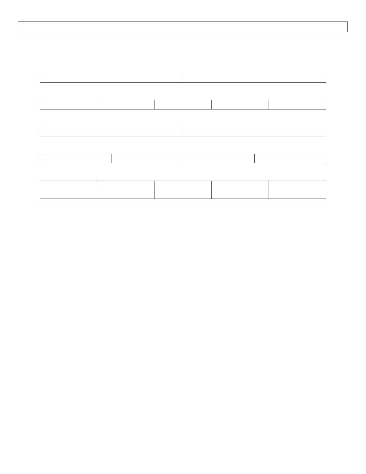
UserSettings:
Filloutthechartbelowandkeepasarecordofyourconfiguration.
Tank
Height= Fill‐H=
LoopFail‐Safe(selectone)
HoldLastValue Empty Full Overfill(21mA) Overfill(22mA)
OutputatEmpty(selectone)
4mAatBottom 20mAatBottom
StartupCondition(selectone)
Empty Mid‐Tank(12mA) FullTank Overfill(22mA)
Advanced(ifselected,identifywhichfilterthatwasactivated)
Increaseoutput
filtering:
Decreaseoutput
filtering:
Stabilizeoutput
indeadband
TurnOFFfast
levelchanges
TurnONnoisy
startfilter
34
Page 35

35
Page 36

36
 Loading...