

Page 1

DataPoint™
Level Sensor Controller
LC52 Series Manual
Flowline, Inc. | 10500 Humbolt Street, Los Alamitos, CA 90720 p 562.598.3015 f 562.431.8507 w flowline.com MN301525 Rev A1
Page 2

Introduction / Table of Contents Step One
The LC52 Series Continuous Relay Controller is a general-purpose level controller which provides single tank
level indication with dual relays and a repeater 4-20 mA output. The LC52 Series features both a single 12A
SPDT and a single 12A Latching SPDT relay. This package allows for a system that can perform automatic
operations (fill or empty) and an alarm operation (high or low). The LC52 series can also be a controller that
can perform dual alarms (2-high, 2-low or 1-high, 1-low). Package the controller with a transmitter that
provides a 4-20 mA output and an enclosure to protect the controller from the elements.
FEATURES
3.5 digit LED display indicates level in customer engineering units.
Fail-Safe relay control of pumps, valves or alarms with a 0 to 60 second delay.
Polypropylene enclosure can be DIN rail mounted or back panel mounted.
Easy setup with push button calibration for display and relay settings.
AC powered
TABLE OF CONTENTS
Specifications/Dimensions: ................................................................................................................................... 3
Components: ............................................................................................................................................. 3
Safety Precautions: ............................................................................................................................................... 5
Make a Fail-Safe System: ......................................................................................................................... 5
Getting Started: ..................................................................................................................................................... 6
Features of the Single Input High or Low Alarm Relay: ............................................................................ 6
Features of the Latching Relay (Automatic Fill or Empty): ........................................................................ 7
Guide to Controls: ..................................................................................................................................... 8
Configuration (Display): ............................................................................................................................ 9
Configuration (Relays): ............................................................................................................................. 9
Setting Values: .......................................................................................................................................... 9
EasyCal Calibration: ............................................................................................................................... 10
Time Delay .............................................................................................................................................. 10
Wiring: ................................................................................................................................................................ 11
Wiring to Intrinsically Safe Transmitters: ................................................................................................. 11
Wiring to Input Terminals: ...................................................................................................................... 11
Setting Input Polarity: .............................................................................................................................. 12
Repeater Output: .................................................................................................................................... 12
Relay & Power Terminals: ..................................................................................................................... 13
VAC Power Input Wiring: ....................................................................................................................... 13
Changing from 120 to 240 VAC: ............................................................................................................ 13
Application Examples: ........................................................................................................................................ 14
Low Level Alarm: .................................................................................................................................... 14
High Level Alarm: .................................................................................................................................... 14
Automatic Fill: ......................................................................................................................................... 15
Automatic Empty: .................................................................................................................................... 15
Appendix: ............................................................................................................................................................ 16
Relay Latch Logic – On vs Off: ............................................................................................................... 16
Controller Logic: ...................................................................................................................................... 16
Factory Reset: ......................................................................................................................................... 16
Lockout Function: ................................................................................................................................... 17
Troubleshooting: ..................................................................................................................................... 17
Exercise: ............................................................................................................................................................ 18
Warranty, Returns & Limitations: ........................................................................................................................ 20
| 2 MN301525 Rev A1
Page 3

Specifications / Dimensions Step Two
Display type: LED, 3.5 digit
Display units: Engineering
Display output: 0 to 999 or 0.0 to 199.9
LED indicators: Power and relay status
LED Bar graph: 4-20 mA span & set points
Memory: Non-volatile
Security: Set point lock out
Contact rating: 250 VAC, 10A
Contact output: Selectable, NO or NC
Contact latch: Selectable ON or OFF
Contact configuration: 1: High or low level alarm
2: High and low level alarm
3: Automatic fill or empty
4: Automatic fill or empty with
Configuration: Push button
Alarm indication: Amber: < 4 mA
Red: > 20 mA
Sensor input: (1) 4-20 mA
Supply voltage: Selectable 120 / 240 VAC
50 - 60 Hz.
Sensor supply: 24 VDC @ 25mA (primary)
28 VDC @ 50mA (secondary)
Loop power: 4-20mA, 18 VDC
Consumption: 5 Watt maximum
Contact delay: 0-60 seconds
Repeater output: 4-20 mA, 12-36 VDC
Ambient temperature: F: -40° to 158°
C: -40° to 70°
Enclosure type: 35 mm DIN (EN 50 022)
Enclosure material: Polypropylene
(U.L. 94 VO)
Classification: General purpose
Contact type: (1) SPDT
(1) Latched SPDT
DIMENSIONS:
alarm
Top View – All Models
INCLUDED COMPONENTS:
Side View – All Models
LC52-1001 - Single input with dual relays, 3.5 digit LED display and repeater output.
Owner’s Manual
MN301525 Rev A1 3 |
Page 4

Specifications / Dimensions Step Two
PANEL DIN RAIL MOUNTING:
The controller may be mounted by either a back panel using two screws through mounting holes located at the
corners of the controller or by snapping the controller on 35 mm DIN Rail.
Note: Always install the controller in a location where it does not come into contact with liquid.
INTERNAL CONTROLLER LOGIC
| 4 MN301525 Rev A1
Page 5

Safety Precautions Step Three
About this Manual: PLEASE READ THE ENTIRE MANUAL PRIOR TO INSTALLING OR USING THIS
PRODUCT. This manual includes information on the continuous relay controller from FLOWLINE: LC521001 series.
User’s Responsibility for Safety: FLOWLINE manufactures several models of controller, with different
mounting and switching configurations. It is the user’s responsibility to select a controller model that is
appropriate for the application, install it properly, perform tests of the installed system, and maintain all
components.
Electrical Shock Hazard: It is possible to contact components on the controller that carry high voltage, causing
serious injury or death. All power to the controller and th e relay circuit( s) it contr ols should b e turned OFF prior
to working on the controller. If it is necessary to make a djustments dur ing powere d oper ation, use ex treme
caution and use only insulated tools. Making adjustments to powered controllers is not recommended. Wiring
should be performed by qualified personn el in accorda nce with all applicab le national , st ate and local electrical
codes.
Flammable or Explosive Applications: The LC52 series continuous relay controllers should not be used
with explosive or flammable liquids, which require an intrinsically safe or explosion proof rating. If you are
unsure of the suitability of a controller for your installation, consult your Flowline representative for further
information.
Install in a Dry location: The controller housing is not designed to be immersed. When installed properly,
it should be mounted in such a way that it does not normally come into contact with liquid. Refer to an
industry reference to ensure that compounds that may splash onto the controller housing will not damage
it. Such damage is not covered by the warranty.
Relay Contact Rating: The relay is rated for a 12 amp resistive load. Many loads (such as a motor during
start-up or incandescent lights) are reactive and may have an inrush current characteristic that may be 10
to 20 times their steady-state load rating. The use of a contact protection circuit may be necessary for your
installation if the 12 amp rating does not provide an ample margin for such inrush currents. In critical
applications, redundant backup systems and alarms must be used in addition to the primary system. Such
backup systems should use different sensor technologies where possible.
Make a Fail-Safe System: Design a fail-safe system that accommodates the possibility of relay or power
failure. If power is cut off to the controller, it will de-energize the relay. Make sure that the de-energized
state of the relay is the safe state in your process. For example, if controller power is lost, a pump filling a
tank will turn off if it is connected to the Normally Open side of the relay.
While the internal relay is reliable, over the course of time relay failure is possible in two modes: under a
heavy load the contacts may be “welded” or stuck into the energized position, or corrosion may buildup on
a contact so that it will not complete the circuit when it should. In critical applications, redundant backup
systems and alarms must be used in addition to the primary system. Such backup systems should use
different sensor technologies where possible.
While this manual offers some examples and suggestions to help explain the operation of FLOWLINE
products, such examples are for information only and are not intended as a complete guide to installing any
specific system.
MN301525 Rev A1 5 |
Page 6

Getting Started Step Four
FEATURES OF A SINGLE INPUT HIGH OR LOW RELAY:
Single Input Relays (Relay 1 or Relay 2 w/ latch turned OFF) are designed to switch from a single set-point. It
turns its internal relay ON or OFF (as set by the invert switch) in response to the presence of liquid, and
changes the relay status back again when the sensor is dry.
High Alarm: Invert is OFF. Relay will energize when the level rises above the high alarm setting and will deenergize when it drops below the high alarm setting.
Low Alarm: Invert is ON. Relay will energize when the level drops below the low alarm setting and will deenergize when it rises above the low alarm setting.
Single input high or low relays may be used with any device that outputs a 4-20 mA signal. The relay is a
single pole, double throw type; the controlled device can be connected to either the normally open or normally
closed side of the relay. A time delay from 0 to 60 seconds can be set before the relay responds to the sensor
input. Typical applications for single input relays are high level or low level switch/alarm operations (opening a
drain valve whenever liquid level rises to a set-point) and over-flow protection (turning off a pump or sounding
an alarm when a high level is reached).
| 6 MN301525 Rev A1
Page 7

Getting Started Step Four
FEATURES OF A LATCHING RELAY (AUTOMATIC FILL OR EMPTY):
The latching relay (relay 2 only) is designed to switch a relay on and off at two different levels. It turns its
internal relay ON or OFF (as set by the invert switch) in response when the level is above the high setting or
below the low setting. The relay will not change its state when the level is between the high and low setting.
Automatic Empty:
Latch is ON & Invert is OFF. Relay will energize when level reaches high setting (both settings are
submersed). Relay will de-energize when level is below the bottom setting (both settings are dry).
Automatic Fill:
Latch is ON & Invert is ON. Relay will energize when level is below the bottom setting (both switches are dry).
Relay will de-energize when level is above the high setting (both settings are wet).
The Latching Relay (Automatic Fill/Empty) may be used with any device that outputs a 4-20 mA signal. The
relay is a single pole, double throw type; the controlled device can be connected to either the normally open or
normally closed side of the relay. Typical applications for Latching Relays are automatic filling (starting fill
pump at a low level and stopping pump at a high level) or automatic emptying operations (opening a drain
valve at a high level and closing valve at low level).
MN301525 Rev A1 7 |
Page 8

Getting Started Step Four
GUIDE TO CONTROLS:
Below is a listing and the location of the different components for the controller:
1. Power indicator: This Green LED lights when AC power is ON.
2. Relay indicator: This Red LED wi ll light whenever the controller energizes the relay, in response to the
transmitter input and after the time delay.
3. AC Pow er terminals: Connection of 120 VAC power to the controller. The setting may be changed to
240 VAC if desired. This requires changing internal jumpers; this is covered in the Installation section of
the manual. Polarity (neutral and hot) does not matter.
4. Relay terminals (NC, C, NO): Connect the device you wish to control (pump, alarm etc.) to these
terminals: supply to the COM terminal, and the device to the NO or NC terminal as required. The switched
device should be a non-inductive load of not more than 10 amps; for reactive loads the current must be
derated or protection circuits used. When the red LED is ON and the relay is in the energized state, the
NO terminal will be closed and the NC terminal will be open.
5. Invert sw itch: This switch reverses the logic of the relay control in response to the switch(es): conditions
that used to energize the relay will now de-energize the relay and vice versa.
6. Time delay: Sets delay from 0-60 seconds. Hold Delay button to increase delay in 5 second increments.
7. Digital display: Shows the current 4-20 mA signal in engineering units.
8. Input terminals: Connect the transmitter wires to these terminals: A 24 VDC power is provided for
current loop with an additional 28 VDC power terminal if required.
9. Latch switch (relay 2): This switch determines how the relay will be energized in response to the two set
points. When LATCH is OFF, the relay responds to set point RLY2A only; when LATCH is ON, the relay
will energize or de-energize only when both set points (RLY2A and RLY2B) are in the same condition (both
wet or both dry). The relay will remain latched until both set points change conditions.
10. Bar Graph: Displays 4-20 mA signal as a percentage of the range.
11. OP / SET: Used to scroll between set points during programming.
12. 20 / Down: Used to decrease display value during programming and for EasyCal™ Span set up.
13. 4 / Up: Used to increase display value during programming and for EasyCal™ Offset set up.
14. Repeater Output: Isolated terminal which reproduces the input 4-20 mA signal. Terminal requires 12-36
VDC power for operation.
| 8 MN301525 Rev A1
Page 9

Getting Started Step Four
CONFIGURATION (DISPLAY):
The key to configure the LC52 series is to match the 4-20mA operational range of the transmitter, using the
OFFSET and SPAN settings to set the 4-20mA operational range on the LC52.
OFFSET: Equivalent to the 4 mA set point on the transmitter. Enter the value you would like to see
when the LC52 receives 4 mA.
SPAN: Equivalent to the 20 mA set point on the transmitter. Enter the value you would like to see
when the LC52 receives 20 mA.
Note: The display is a 3.5 digit display. The smallest value for the display is 0.0. The largest value on the
display is 999.
CONFIGURATION (RELAYS):
Once the OFFSET and SPAN are set, the relays are configured using the RLY1, RLY2 and RLY2B settings.
All relay settings must be between the OFFSET and SPAN values. Note: Setting the relays equal to or outside
the operational range of OFFSET and SPAN will prevent the relays from functioning.
RLY1: Can be used as a high or low level alarm relay.
RLY2A: Can be used as a high or low level alarm relay with Latch OFF or as an automatic fill or empty
operation with RLY2B and Latch ON.
RLY2B: Used as the second setting for an automatic fill or empty operation. Must be used with RLY2A
and with Latch ON.
SETTING VALUES:
RLY2B will not show during the programming section with Latch Off.
1. Press the SET button once. Immedi ately, the LED bar graph will begin to flash one
Green bar next to OFFSET.
2. Use UP / DWN buttons to change display to the desired OFFSET value.
3. Press the SET button again. Immediately, the LED bar graph will jump one Green bar
to the right next to SPAN.
4. Use UP / DWN buttons to change display to the desired SPAN value.
5. Press the SET button again. Immediately, the LED bar graph will jump one Green bar
to the right next to RLY1.
6. Use UP / DWN buttons to change display to the desired RLY1 value.
7. Press the SET button again. Immediately, the LED bar graph will jump one Green bar
to the right next to RLY2A.
8. Use UP / DWN buttons to change display to the desired RLY2A value.
9. Press the SET button again. Immediately, the LED bar graph will jump one Green bar
to the right next to RLY2B.
10. Use UP / DWN buttons to change display to the desired RLY2B value.
11. Press the SET button again. Immediately, the LED bar graph will return back to it
normal operation of solid bars.
MN301525 Rev A1 9 |
Page 10

Getting Started Step Four
Note: The half digit will appear when scaling between 0.0 and 199.9. If the display is scaled above 199.9, the
half digit and the decimal point disappear.
If OFFSET = 0 and SPAN = 190, then the display will be scaled as follows: 0.0 to 190.0.
However, if OFFSET = 0 and SPAN = 200, then the display will be scaled as follows: 0 to 200. The
decimal point and half digit will disappear.
EASYCAL CALIBRATION:
The Offset and Span points may be programmed directly to a specific level in the tank. These are the EasyCal
4 (Empty tank) and EasyCal 20 (Full tank) values.
Note: the level of the tank must physically be at its desired level when using EasyCal. If not, the EasyCal will
accept the level and the values on the display will be incorrect. Use the factory reset to start over if this occurs.
To calibrate EC4, set the tank to the new Offset level. Press [4] button once
and [E] will appear in the display. Press [4] button again and [C] will appear in
the display and EC4 is set.
To calibrate EC20, set the tank to the new Span level. Press [20] button once
and [E] will appear in the display. Press [20] button again and [C] will appear in
the display and EC20 is set.
TIME DELAY:
The time delay can be adjusted from 0 seconds to 60 seconds in increments
of 5 seconds. Press and hold the Delay button for each relay to increase the
delay in 5 second steps. The delay will drop to 0 seconds after 60 seconds
has been reached. The delay applies to both the Make and Break side of the
relay. The delay can be used to prevent relay chatter, especially when you
have a liquid level that is turbulent.
| 10 MN301525 Rev A1
Page 11

Wiring Step Five
WIRING TO INPUT TERMINAL:
Signal input is always through the 24 VDC terminal. The 28 VDC terminal is used as an
alternative power supply for three-wire devices. Please note a difference between 2-wire
and 3-wire level transmitters and sourcing and sinking modes below. Below is a quick review
of wiring the LC52 series to common 4-20 mA transmitters.
EchoPod (UG01 and UG03 series),
EchoSonic (LU23, LU27, LU28 & LU29 series)
& EchoPod (DL10, DL14, DL24 & DL34 series)
Sourcing mode (Factory Setting)
DeltaSpan pressure (LD30, LD31, LD32, LD34 &
LD35 series) & FloaTek (LV55 series)
Sourcing Mode (Factory Setting)
EchoPod (UG06 and UG12 series)
EchoSpan (LU80, LU81, LU83 & LU84 series) &
EchoSwitch (LU74, LU77 & LU78)
Sourcing Mode (Factory Setting)
EchoWave (LG10 & LG11 series)
Sinking Mode
(internal jumper must be changed)
WIRING TO INTRINSICALLY SAFE TRANSMITTERS:
Note: Always refer to the transmitters control drawing for wiring in an intrinsically safe application
Echotouch (Intrinsically Safe)
US01-0001-_ _ & US01-0011-_ _
US03 -0001-_ _ & US03-0011-_ _
US06-000_-_ _ & US06-001_-_ _
US12-000_-_ _ & US12-001_-_ _
Sinking mode (internal jumper must be
changed)
MN301525 Rev A1 11 |
Page 12

Wiring Step Five
SETTING INPUT POLARITY (SOURCING VS. SINKING MODES):
The LC52 can be set in one of two modes, sourcing and sinking. The LC52 is shipped from the factory in the
sourcing mode. This is compatible with any loop powered transmitter such as the EchoSonic (LU23, LU27,
LU28 & LU29 series), EchoSpan (LU80, LU81, LU83 & LU84 series), EchoSwitch (LU74, LU77 & LU78
series), EchoPod (DL10, DL14, DL24 & DL34 series), DeltaSpan pressure (LD30, LD31, LD32, LD34 & LD35
series) and FloaTek (LV55 series) with no adjustment required. If using a US01, US03, US06 or US12 series,
follow the instructions below.
1. Remove the back panel of the controller and gently slide the printed circuit
board (PCB) from the housing. Use caution when removing the PCB.
2. Locate jumpers JWA and JWB on the PCB.
3. To change from sourcing to sinking, remove jumper from JWA and place on
JWB. The LC52 is shipped from the factory in the sourcing mode (JWA
active).
4. Gently return PCB into housing and replace back panel.
Note: Loop powered devices can operate in either the souring or sinking
modes.
EchoPod (UG01, UG03, UG06 & UG12 series),
No
Change
Required
EchoSonic (LU23, LU27, LU28 & LU29 series),
EchoSpan (LU80, LU81, LU83 & LU84 series),
EchoPod (DL10, DL14, DL24 & DL34 series),
EchoSwitch (LU74, LU77 & LU78 series)
Sinking
Devices
DeltaSpan (LD30, LD31, LD32, LD34 & LD35 series) &
FloaTek (LV55 series)
Change
Required
REPEATER OUTPUT:
EchoTouch (US01, US03, US06 & US12 series)
EchoWave (LG10 & LG11 series)
Sourcing
Devices
The isolated repeater output reproduces the input 4-20 mA
current signal. This signal can be repeated to any other device
that accepts a 4-20 mA input, such as a PLC, DCS, SCADA,
chart recorder or another display.
or
Loop
Sourcing Mode
Sinking Mode
Note: The repeated 4-20 mA signal is not an excited output. An
external power supply is required and should not exceed a
maximum of 36 VDC.
See the wiring diagram to the right for instructions in wiring all
three components (repeater output, power supply and the new
device) in series with each other.
| 12 MN301525 Rev A1
Page 13

Wiring Step Five
RELAY AND POWER TERMINALS
Depending on the model selected, there will be either
one or two relays. The label for the relay applies for
both relays. Each terminal has a Normally Open
(NC), Common (C) and Normally Open (NO) terminal.
The relay(s) is(are) a single pole, double throw
(SPDT) type rated at 250 Volts AC, 10 Amps, 1/4 Hp.
Note: The relay contacts are true dry contacts.
There is no voltage sourced within the relay contacts.
Note: The "normal" state is when the relay coil is deenergized and the Red relay LED is Off / deenergized.
VAC POWER INPUT WIRING:
The Power Terminal is located next to the Relay(s).
Observe the Power Supply label, which identifies the
power requirement (120 or 240 VAC) and the terminal
wiring.
Note: Polarity does not matter with the AC input
terminal.
CHANGING FROM 120 TO 240 VAC:
The LC52-1001 is shipped from the factory configured as a 120 VAC powered device. To switch to 240 VAC,
follow the instructions below.
1. Remove the back panel of the controller and gently slide the printed
120 VAC Jumper Setting
circuit board (PCB) from the housing. Use caution when removing the
PCB.
2. Locate jumpers JW1, JW2 and JW3 on the PCB.
3. To change from 120 VAC to 240 VAC:
a. Remove the jumpers from JW1 & JW2 and add a jumper to JW3.
4. To change from 240 VAC to 120 VAC:
240 VAC Jumper Setting
a. Remove the jumper from JW3 and add jumpers to JW1 & JW2.
5. Gently return PCB into housing and replace back panel.
240 VAC OPTION:
When ordering the 240 VAC version of the LC52 series, the controller will arrive configured for 240 VAC
operation. 240 VAC version will include a –E to the part number (i.e. LC52-1001-E).
MN301525 Rev A1 13 |
Page 14

Application Examples Step Six
LOW LEVEL ALARM:
The goal is to make sure that an operator is notified if the liquid level falls below a
certain point. If it does, an alarm will sound, alerting the operator of a low level. A
setting for the low level is configured in the controller.
In this application, the level where the alarm will be below the normal liquid level
for this application. When the liquid lowers below the low level set point, the relay
contact will close causing the alarm to activate.
Normal status for the application is for the controller to hold the relay open with the
alarm wired through the Normally Closed contact. The Relay will be energized, the
relay LED will be On and Invert will be Off. When the level drops level the set
point, the relay will de-energize causing the contact to close allowing the alarm to
activate.
To do this, connect the hot lead of the alarm to the NC
side of the relay terminal of the controller. If power is
lost, the relay will be de-energized, and the alarm will
sound (if there is still power to the alarm circuit itself).
Note: If power is accidentally cut to the controller, the
level switch’s ability to notify the operator of a low level
alarm could be lost. To prevent this, the alarm circuit
should have a non-interruptible power supply or some
other independent power source.
HIGH LEVEL ALARM:
In the same manor, this system can be used to sound an alarm when fluid reaches
a high level, with just a change in the location of the set point and the setting of the
Invert switch.
The alarm is still connected to the NC side of the relay to allow for a power failure
alarm.
The sensor is normally dry. In this condition, we want the relay to be energized so
the alarm does not sound: i.e., the Red relay LED should be on whenever the Input
LED is Amber. So we turn Invert On. If the fluid level rises to the high sensor
point, the sensor goes on, the relay de-energizes, and the alarm sounds.
| 14 MN301525 Rev A1
Page 15

Application Examples Step Six
AUTOMATIC FILL:
This system consists of a tank with a valve controlled by the LC52. At a low set
point, the valve opens, filling the tank. At the high set point, the valve closes.
Part of a proper fail-safe design for this particular
system is that if power is lost to the controller for any
reason, the valve filling the tank must close.
Therefore, we connect the valve to the NO side of
the relay. When the relay is energized, the valve will
open and fill the tank. The relay indicator will
correspond directly to the Open/Close status of the
valve.
Determining the settings of LATCH and INVERT: This is the way the system
must operate:
When the liquid level is below the low relay set point (start fill), the valve
will open, starting to fill the tank.
When the liquid is above the low relay set point (start fill), the valve will
remain open.
When the liquid reaches the high relay set point (stop fill), the valve will
close.
When the liquid lowers below the high relay set point (stop fill), the valve will remain closed.
Latch: In any 2-setpoint relay configuration, LATCH must be ON.
Invert: Referring to the logic chart in Step Nine, we look for the setting that will de-energize the relay (valve
close) when both relay set points are wet. In this system, Invert should be ON.
AUTOMATIC EMPTY:
Similar system logic can be used for an automatic empty operation. In this
example, we will use a pump to empty a tank. The system still consists of a
tank with a high set point (Start Empty), a low level set point (stop empty), a
sensor and a pump that is controlled by the controller.
Note: Fail-safe design is critical in an application where the tank is passively
filled. A power failure to the controller or the pump circuits may cause the tank
to overflow. A redundant high alarm is critical to prevent an overflow.
Connect the pump to the NO side of the relay. In this case, Invert should be
OFF, when the relay is energized, the pump will run
and empty the tank. The relay indicator will
correspond directly to the on/off status of the pump.
Note: If the pump motor load exceeds the rating of
the controller’s relay, a stepper relay of higher
capacity must be used as part of the system design.
MN301525 Rev A1 15 |
Page 16
Appendix Step Seven
RELAY LATCH LOGIC – ON VS OFF:
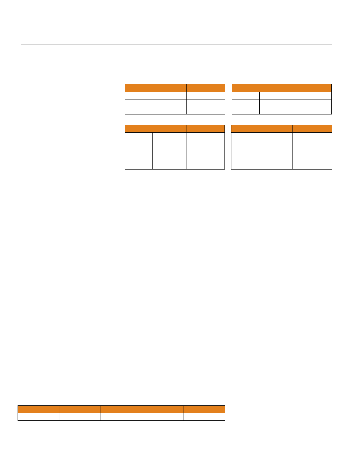
Relay 2 can either be an independent relay (high level or low level) with Latch OFF or can be a latching relay
(automatic fill or empty) with Latch ON.
With Latch OFF, Relay 2 will only
respond to RLY2A. RLY2B will be
ignored with Latch OFF.
With Latch ON, Relay 2 will
actuate when the level is above
RLY 2A. The relay will not change
its condition if the level is between
RLY 2A and RLY 2B. The relay
will reverse its state when the level
Invert OFF Latch OFF
Rly 2A Rly 2B Relay
Wet
Dry
No Effect
No Effect
ON
OFF
Invert OFF Latch ON
Rly 2A Rly 2B Relay
Wet
Dry
Wet
Dry
Wet
Wet
Dry
Dry
ON
No Change
No Change
OFF
Invert ON Latch OFF
Rly 2A Rly 2B Relay
Wet
Dry
No Effect
No Effect
OFF
ON
Invert ON Latch ON
Rly 2A Rly 2B Relay
Wet
Dry
Wet
Dry
Wet
Wet
Dry
Dry
OFF
No Change
No Change
ON
is below RLY 2B relay set points.
CONTROLLER LOGIC:
Please use the following guide to understand the operation of the controllers.
1. Power LED: Make sure the Green power LED is ON when power is supplied to the controller.
2. Bar Graph LED: The bar graph LED on the controller will always indicate the proportional 4-20 mA input
signal going to the LC52 controller. i.e.: if the tank is 25% full, then 25% of the bar graph will be lit Green.
If a single Amber bar appears, this indicates an input current of less than 4mA. If a single Red LED
appears, this indicates an input current greater than 20 mA. Use this feature to confirm the input signal for
the LC52.
3. Relay LEDs : The normal state of the relay is when the LED is OFF. When the relay becomes energized,
the Red LED will light. If power is removed from the controller, the relay will return to the normal state
(LED OFF).
4. Display: Will indicate the proportional level of the liquid based upon the 4-20 mA input. If EasyCal is used
for either the empty tank level, full tank level or both, the display will ignore the 4-20 mA input signal and
use the EasyCal setting as its empty and/or full position.
FACTORY RESET:
Returns the LC52 to its original factory set points, including setting the
OFFSET to 4 mA and the SPAN to 20 mA. To perform a Factory Reset, first
remove power to the controller. Hold both the 4/UP and 20/DWN buttons
while adding power to the LC52. An “F” for Factory Reset will appear in the
display indication the Factory Reset was achieved. If an “E” for Error appears,
the Factory Reset was not performed and you will need to try again.
Note: make sure both buttons are pressed while adding power. The “E” will
appear if only one of the buttons is pressed.
FACTORY SETTINGS FOR LC52 SERIES:
OFFSET SPAN RLY 1 RLY 2A RLY 2B
4.0 20.0 6.0 18.0 8.0
| 16 MN301525 Rev A1
Page 17
Appendix Step Seven
LOCK OUT FUNCTION:
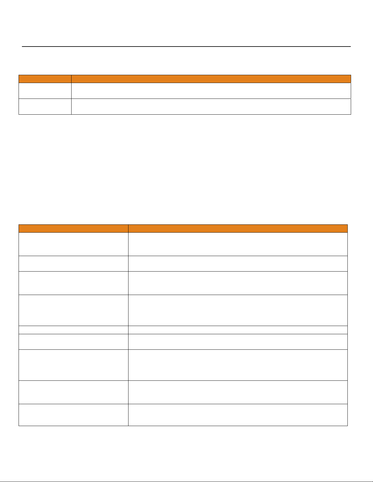
The buttons on the face of the LC52 series can be disengaged or locked out:
Function Instructions
Lockout
Buttons
Unlock
Buttons
Lock Out ON
(LOCKED)
Press both delay buttons and the DWN button simultaneously (see below left). This will
lockout all of the buttons and prevent an accidental changing of settings.
Press both delay buttons and the UP button simultaneously (see below right).
Lock Out OFF
(UNLOCKED)
TROUBLESHOOTING:
PROBLEM SOLUTION
Display is not reading correct
level.
First check the Bar Graph to make sure it is indicating the correct level.
If not, check transmitter. If so, perform a factory reset on the LC52 and
reset values.
Bar Graph is not indicating the
correct level.
Bar Graph shows a single Amber
bar.
Check the transmitter’s 4-20 mA output making sure it is spanned
correctly for the application.
This indicates a current input less than 4mA. Check for loose or open
wires between the transmitter and LC52 and check the output of the
transmitter.
Bar Graph shows all Green bars
and a single Red bar.
This indicates a current input greater than 20mA. Remove power
immediately. Check for a short in the wiring between the transmitter
and LC52 or for some other power source that is affecting the input
loop.
RLY 2B does not appear. Flip Latch switch to ON.
Relay switches only from RLY 2A
Latch is turned OFF. Flip the latch switch to turn ON.
(ignores RLY 2B).
Level reaches alarm ON, but relay
is OFF.
First, check to make sure the input LED is ON. If not, check wiring to
sensor.
Second, check status of Relay LED. If incorrect, flip the Invert switch to
change the relay state.
Pump or Valve is supposed to
stop, but it does not.
First, check to make sure the bar graph is indicating the correct level.
Next check the relay settings. Finally, check status of Relay LED. If
incorrect, flip the Invert switch to change the relay state.
Controller is powered, but nothing
happens.
First check the Power LED to make sure it is Green. If not, check the
wiring, power and make sure the terminal is seated correctly.
MN301525 Rev A1 17 |
Page 18

Exercise Step Eight
AUTOMATIC FILL WITH HIGH LEVEL ALARM USING UNITS OF HEIGHT OF LIQUID (INCHES):
The following exercise demonstrates inventory control
with automatic filling and a high level alarm. The
usable range is 60 inches of liquid. The pump starts
filling at 10 inches of liquid and stops filling at 50
inches of liquid. A high level alarm occurs at 55
inches of liquid.
Enter all values into the LC52 in inches of liquid:
OFFSET is the corresponding 4 mA setting.
SPAN is the corresponding 20mA setting.
RLY2A and RLY2B are dedicated to the filling
of the tank because RELAY2 is a latching
relay.
RLY1 is dedicated to the high level alarm
because RELAY1 is a single set point relay.
Use the following values for programming the LC52-1001.
OFFSET
0.0
AUTOMATIC FILL WITH HIGH LEVEL ALARM USING UNITS OF VOLUME (GALLONS):
SPAN
60.0
RLY 1
55.0
RLY 2A
50.0
RLY 2B
10.0
The next exercise demonstrates the same inventory
control with automatic filling and a high level alarm.
However, the units have been changed from inches to
gallons. Within the tank, 1” = 5 gallons of liquid. The
usable range is now 300 gallons of liquid. The pump
starts filling at 50 gallons of liquid and stops filling at
250 gallons of liquid. A high level alarm occurs at 275
gallons of liquid.
Enter all values into the LC52 in gallons of liquid.
OFFSET is the corresponding 4 mA.
SPAN is the corresponding 20 mA setting.
RLY2A and RLY2B are dedicated to the filling
of the tank because RELAY2 is a latching
relay.
RLY1 is dedicated to the high level alarm
because RELAY1 is a single set point relay.
Use the following values for programming the LC52-1001.
OFFSET
0
| 18 MN301525 Rev A1
SPAN
300
RLY 1
275
RLY 2A
250
RLY 2B
50
Page 19

Exercise Step Eight
INVENTORY CONTROL WITH HIGH AND LOW LEVEL ALARMS USING UNITS OF HEIGHT OF LIQUID (INCHES):
The following exercise demonstrates inventory control
with a high and low level alarm. The usable range is
between 16 and 56 inches of liquid. The high level
alarm occurs at 50 inches of liquid and the low level
alarm occurs at 20" of liquid.
Enter all values into the LC52 in inches of liquid:
OFFSET is the corresponding 4mA setting.
SPAN is the corresponding 20mA setting.
RLY1 is dedicated to the high level alarm
because RELAY1 is a single set point relay.
RLY2A is dedicated to the low level alarm
because Latch is turned OFF on Relay 2.
Use the following values for programming the LC52-1001.
OFFSET
16.0
INVENTORY CONTROL WITH HIGH AND LOW LEVEL ALARMS USING UNITS OF VOLUME (GALLONS):
SPAN
56.0
RLY 1
50.0
RLY 2A
20.0
RLY 2B
N/A
The next exercise demonstrates the same inventory
control with a high and low level alarm. However, the
units have been changed from inches to gallons.
Along the straight side of the tank, 1” = 5 gallons of
liquid. The usable range is now from 50 to 250
gallons of liquid. The high level alarm occurs at 220
gallons of liquid. The low level alarm occurs at 70
gallons of liquid.
Enter all values into the LC52 in gallons of liquid:
OFFSET is the corresponding 4mA setting.
SPAN is the corresponding 20mA setting.
RLY1 is dedicated to the high level alarm
because RELAY1 is a single set point relay.
RLY2A is dedicated to the low level alarm
because the latch is turned off on Relay 2.
Use the following values for programming the LC52-1001.
OFFSET
50
SPAN
450
RLY 1
120
RLY 2A
390
RLY 2B
N/A
MN301525 Rev A1 19 |
Page 20

Warranty, Returns and Limitations Step Nine
WARRANTY
Flowline warrants to the original purchaser of its products that such products will be free from defects in
material and workmanship under normal use and service in accordance with instructions furnished by Flowline
for a period of two years from the date of manufacture of such products. Flowline's obligation under this
warranty is solely and exclusively limited to the repair or replacement, at Flowline's option, of the products or
components, which Flowline's examination determines to its satisfaction to be defective in material or
workmanship within the warranty period. Flowline must be notified pursuant to the instructions below of any
claim under this warranty within thirty (30) days of any claimed lack of conformity of the product. Any product
repaired under this warranty will be warranted only for the remainder of the original warranty period. Any
product provided as a replacement under this warranty will be warranted for the full two years from the date of
manufacture.
RETURNS
Products cannot be returned to Flowline without Flowline's prior authorization. To return a product that is
thought to be defective, go to flowline.com, and submit a customer return (MRA) request form and follow the
instructions therein. All warranty and non-warranty product returns to Flowline must be shipped prepaid and
insured. Flowline will not be responsible for any products lost or damaged in shipment.
LIMITATIONS
This warranty does not apply to products which: 1) are beyond the warranty period or are products for which
the original purchaser does not follow the warranty procedures outlined above; 2) have been subjected to
electrical, mechanical or chemical damage due to improper, accidental or negligent use; 3) have been modified
or altered; 4) anyone other than service personnel authorized by Flowline have attempted to repair; 5) have
been involved in accidents or natural disasters; or 6) are damaged during return shipment to Flowline. Flowline
reserves the right to unilaterally waive this warranty and dispose of any product returned to Flowline where: 1)
there is evidence of a potentially hazardous material present with the product; or 2) the product has remained
unclaimed at Flowline for more than 30 days after Flowline has dutifully requested disposition. This warranty
contains the sole express warranty made by Flowline in connection with its products. ALL IMPLIED
WARRANTIES, INCLUDING WITHOUT LIMITATION, THE WARRANTIES OF MERCHANTABILITY AND
FITNESS FOR A PARTICULAR PURPOSE, ARE EXPRESSLY DISCLAIMED. The remedies of repair or
replacement as stated above are the exclusive remedies for the breach of this warranty. IN NO EVENT SHALL
FLOWLINE BE LIABLE FOR ANY INCIDENTAL OR CONSEQUENTIAL DAMAGES OF ANY KIND
INCLUDING PERSONAL OR REAL PROPERTY OR FOR INJURY TO ANY PERSON. THIS WARRANTY
CONSTITUTES THE FINAL, COMPLETE AND EXCLUSIVE STATEMENT OF WARRANTY TERMS AND NO
PERSON IS AUTHORIZED TO MAKE ANY OTHER WARRANTIES OR REPRESENTATIONS ON BEHALF
OF FLOWLINE. This warranty will be interpreted pursuant to the laws of the State of California. If any portion
of this warranty is held to be invalid or unenforceable for any reason, such finding will not invalidate any other
provision of this warranty.
For complete product documentation, video training, and technical support, go to flowline.com.
For phone support, call 562-598-3015 from 8am to 5pm PST, Mon - Fri.
(Please make sure you have the Part and Serial number available.)
| 20 MN301525 Rev A1
 Loading...