

Page 1

Page 2

2
Page 3

INTRODUCTION SectionOne
The senor utilizes TDR (Time Domain Reflectometry) technology. It is best described as low‐energy, high‐
frequencyelectromagneticimpulses,generatedbythesensor’scircuitrythatispropagatedalongtheprobeas
itis immergedinthe liquidtobe measured.Impulses hitthesurface ofthemedia andpartof theimpulse
energy is reflected back up the probe to the circuitry. Level Measurementiscalculatedfromthetime
differencebetweentheimpulsessent and theimpulses reflected.Thesensoranalyzestheleveloutputasa
continuousmeasurement readingfromits analogoutput. TDR‐Sensorsarealso knownasGuided Radarsor
GuidedWaveRadars(GWR).
NewFeatures
Precisecontinuouslevelmeasurementinonedevice
Completegalvanic insulationof deviceelectronicsfrom itsinputs/outputs and thetankpotential (no
problemswithelectrochemicalcorrosionprotection)
Highly robust measurement due to 3‐wire design, innovative signal analysis and disturbance signal
suppression
TableofContents
Introduction: .........................................................................................................................................................3
Specifications:..........................................................................................................................................4‐5
Dimensions:.................................................................................................................................................6
AboutthisManual:.....................................................................................................................................7
GettingStarted(SetupOverview):..........................................................................................................................8
PartNumbers:.............................................................................................................................................9
Probelength:.............................................................................................................................................10
MeasurementRange:...............................................................................................................................13
HeightofLiquidvs.VolumeofLiquid:......................................................................................................15
Installation(MountingConsiderations):...............................................................................................................16
Installationtips:...................................................................................................................................18‐21
Wiring(AnalogOutput):........................................................................................................................................22
CommonWiringtoDisplays,Controllers&PLCs:.....................................................................................24
Configuration:.......................................................................................................................................................25
USBFobinterface:....................................................................................................................................25
Sensorconfiguration:................................................................................................................................26
Tankshapeselection:................................................................................................................................27
DimensionalEntry:....................................................................................................................................27
Tanklevelconfiguration:..........................................................................................................................28
Writetounit:.............................................................................................................................................28
EmptySignalScan:................................................................................................................................................29
Appendix:..............................................................................................................................................................31
EchoCurve:...............................................................................................................................................31
Sensorconfiguration:...........................................................................................................................32‐34
Tankshapeselection:...........................................................................................................................34‐35
DimensionalEntry:...............................................................................................................................35‐36
TankLevelConfirmation:..........................................................................................................................37
Writetounit:.............................................................................................................................................38
CuttingtheProbe:................................................................................................................................39‐41
Troubleshooting:......................................................................................................................................42
Warranty/Disclaimer:...........................................................................................................................................43
3
Page 4

INTRODUCTION SectionOne
Electrical
Analogoutput: 4to20mA,3‐wire
Totalloadresistance: <250Ω
Lowerrangevalue: 4.0mA(span0%)
Upperrangevalue: 20.0mA(span100%)
Responsetime: 5s
Supplyvoltage: 10to30VDC(reverse‐polarityprotected)
Currentconsumption:<50mAat24VDC
Start‐uptime: <6s
Cableterminals: terminalblockforwires16to26AWG(solidorstranded)
Measurement
Referencecondition:(dielectricconstant[εr]=80,watersurface,tank01m,DN200metalflange)
Accuracy: ±3mm
Repeatability: <2mm
Resolution: <2mm
Probetype:
Rod: 4mm
Cable: 4mm,type7x19
Coaxial: 21.3mm(0.843”)½”pipe
Probelength StandardLengths
Rod: LVRD11: 9.84’ (3.0m)
LVRD11‐3FT: 3.0’ (0.91m)
LVRD11‐6FT: 6.0’ (1.82m)
Coaxial: LVRD12: 9.84’ (3.0m)
LVRD12‐3FT: 3.0’ (0.91m)
LVRD12‐6FT: 6.0’ (1.82m)
Cable: LVRD13: 18.0’ (5.5m)
CustomProbe [canbeorderedin5mm(0.2”)incrementsfromthereferencepoint]
Rod: 2’to9.8’ (0.61to3.0m)
Cable: 3.3’to18’(1.0to5.5m)
Coaxial: 2’to9.8’ (0.61to3.0m)
Probeloading
Rod: Maximumlateralload: 6Nm…(0.2kgat3m)
Cable: Maximumtensileload: 5kN
Coaxial: Maximumlateralload: 100Nm…(1.67kgat6m)
Topdeadband: 100mm(4”)
Bottomdeadband: 50mm(2”)
ApplicationSpecifications
IntendedInstallation:
Rod: Metallictankorbelowgradeconcretebasin
Cable: Metallictankorbelowgradeconcretebasin
Coaxial: Non‐metallic,plastic,fiberglassormetallictankorbelowgradeconcretebasin
Dielectric[εr] >1.8
Conductivity: norestrictions
Density: norestrictions
4
Page 5
INTRODUCTION SectionOne
ApplicationSpecifications(continued)
Processtemperature
Rod: F:‐40°to302° C:‐40°to150°
Cable: F:‐40°to302° C:‐40°to150°
Coaxial: F:‐40°to266° C:‐40°to130°
Ambienttemperature
Operation: F:‐13°to176° C:‐25°to80°C
Storage: F:‐40°to185° C:‐40°to85°C
Applicationpressure: ‐14.5to250psi ‐1barto17.2bar
Rateoflevelchange: 1”/s
MechanicalSpecifications
Wettedmaterials:
Rod: 1.4404/316LSS,PEEK
Cable: 1.4404/316SS,PEEK
Coaxial: 1.4404/316LSS,PEEK
Housingmaterials
Housingbodyandcover: AluminumalloyENAC‐AlSi9Cu3(DINEN1706),epoxyspray
coating(~70μm)otheralloysandcoatingsonrequest.
covero‐ring: siliconerubber(ElastosilR750/50)
screws;coverlockingscrew; 1.4301/304externalearthterminal
screw: tinplatedstainlesssteel1.4301/304
Housingrating: IP66,NEMA4
Cableentries: Singlecableentry½”NPT
Cordgrip: ½”NPT,FerriteBeadincluded
Cordgripmat’l: Nylon
CordgripCable
MinimumSize: 0.170”(4.3mm)
MaximumSize: 0.450”(11.4mm)
Processmount: ¾”NPT
Compliance: CE:EN61326‐1:2013&EN55011ClassAGroup1
CRN
RoHS
5
Page 6
INTRODUCTION SectionOne
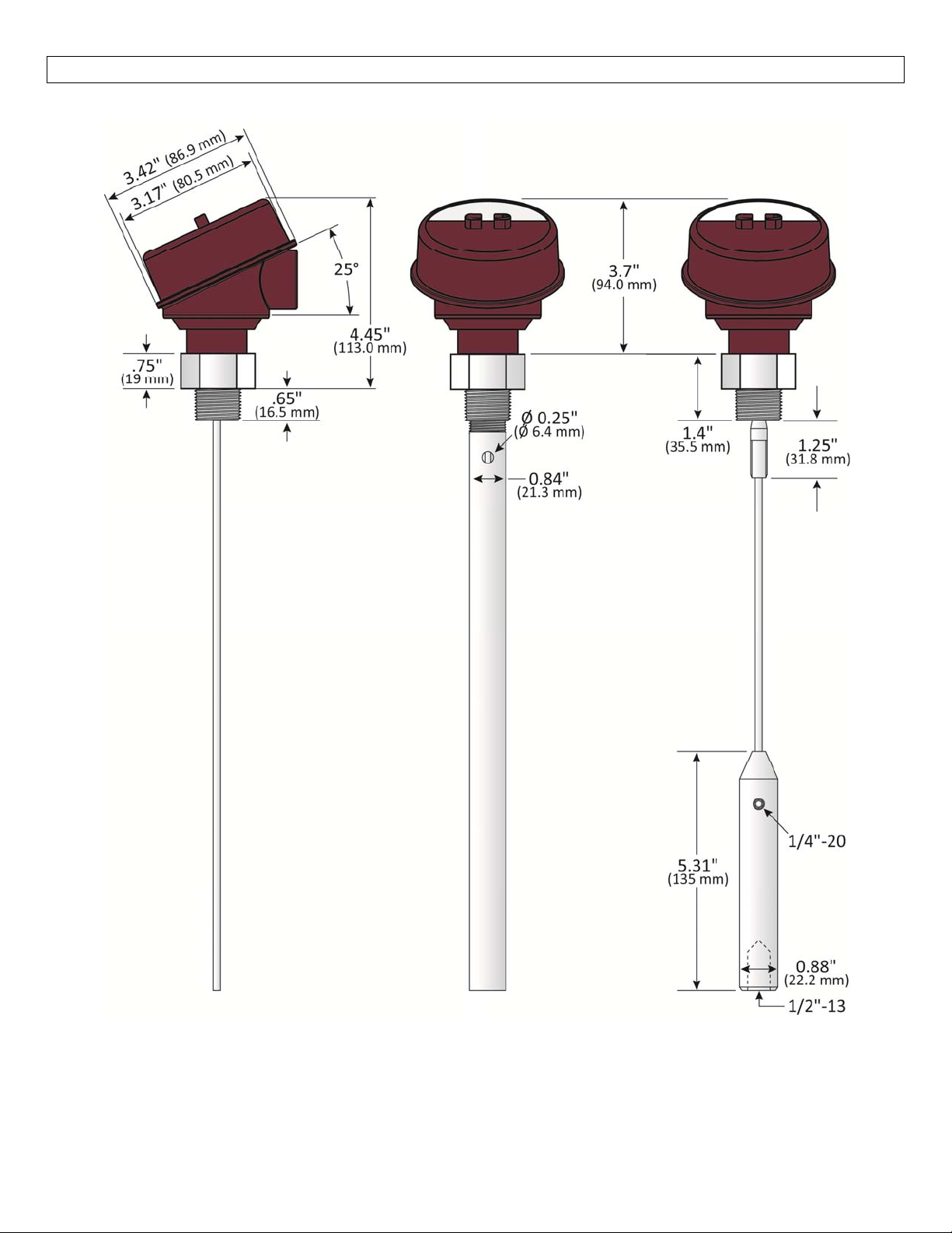
Dimensions:
Rod Coaxial Cable
6
Page 7
INTRODUCTION SectionOne
Aboutthis Manual:PLEASEREADTHEENTIREMANUALPRIORTOINSTALLINGORUSINGTHISPRODUCT.
This manualincludes informationon the LVRD10series Guided WaveRadarLevelTransmitterfromOmega
Engineering®. Please refer to the part number located on the switch label to verify the exact model
configuration,whichyouhavepurchased.
User’s Responsibility for Safety: Omega Engineering® manufactures a broad range of level sensing
technologies.Whileeachofthesesensorsisdesignedtooperatein awide varietyof applications,itis the
user’sresponsibilitytoselectasensormodelthatisappropriatefortheapplication,installitproperly,perform
tests of the installed system, and maintain all components. The failure to do so could result in property
damageorseriousinjury.
ProperInstallationandHandling:Onlyprofessionalstaffshouldinstalland/orrepairthisproduct.Never
overtightenthesensorwithinthefitting.Alwayscheckforleakspriortosystemstart‐up.
WiringandElectrical:Asupplyvoltageof10to30VDCisrequiredtopowertheLVRD10Series.Electrical
wiring of the transmitter should be performed in accordance with all applicable national, state, and local
codes.
MaterialCompatibility:Theenclosureismadeofmetal.Makesurethatitischemicallycompatiblewith
theapplicationmedia.
Enclosure:Whilethesensorhousingisliquid‐resistanttheLVRD10Seriesisnotdesignedtobeoperational
whenfullyimmersed.Itshouldbemountedtoinsuretheenclosuredoesnotcomeintocontactwiththe
applicationmediaundernormaloperationalconditions.Theprobeisdesignedforfullliquidcontact.
Handling Static‐SensitiveCircuits/Devices: When handlingthetransmitter, thetechnicianshould follow
these guidelines to reduce any possible electrostatic charge build‐up on the technician’s body and the
electronicpart.
1. Alwaystouchaknowngoodgroundsourcebeforehandlingthepart. Thisshould be repeatedwhile
handlingthe part andmorefrequently aftersittingdownfrom astandingposition, slidingacrossthe
seatorwalkingadistance.
2. Avoidtouchingelectricalterminalsofthepartunlessmakingconnections.
3. DONOTopentheunitcoveruntilitistimetocalibrate.
MakeaFail‐SafeSystem: Designa fail‐safesystem thataccommodates thepossibility ofswitch and/or
powerfailure.OmegaEngineering®recommendstheuseofaredundantbackupsystemandalarminaddition
totheprimarysystem.
Flammable,ExplosiveorHazardousApplications:TheLVRD10Seriessensorisnotcertifiedforapplication
inahazardouslocations.
7
Page 8

GETTINGSTARTED SectionTwo
SetupOverview
Belowhighlightstheinitialstepsinsettingupyoursensorforoperation.
1. CheckPartNumber(SectionTwo)
a. Confirmthatthesensor’spartnumbermatchestheorderedpartnumberandallcomponents
areprovidedwiththemodeldelivered.
2. MeasureProbe&Installation(SectionTwo)
a. Priortoinstallation,measurethelengthoftheprobe.Confirmthattheprobelengthmatches
theactualinstallationlocation.
b. Iftheprobelengthistoolong,refertoCuttingtheProbeinSection8.
c. Understand the location of the sensor’sMeasurement Range as wellas Minimum Fill‐Height
andMaximumFill‐Heightsettings.
3. Installthesensor(SectionThree)
a. Section3containsinformationonthelocationandmechanicalinstallationofthesensor.
4. Wirethesensor(SectionFour)
a. Section4containsinformationonelectricalwiringandpowerrequirementsforthesensor.
5. ConfigureSensorwithLVCN414‐SWSoftware(SectionFive)
a. Section5containsinformationonusingtheLVCN414‐SWconfigurationsoftware.
6. PerformanEmptyScan(SectionSix)
a. Section6containsinformationonhowtorunanemptyscan.
b. Anemptyscanmaynotberequiredonasensorthathasacoaxialprobe.
8
Page 9
GETTINGSTARTED SectionTwo
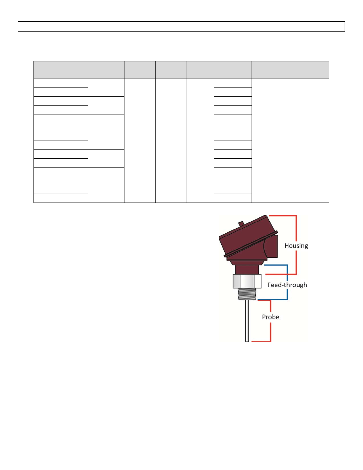
Components:LVRD10Seriesisofferedin12differentmodels.Dependingonthemodelpurchased,youmayor
maynothavebeenshippedtheconfigurationcomponentshownbelow.
Part
Number
LVRD11‐B
LVRD11 Yes
LVRD11‐3FT‐B
LVRD11‐3FT Yes
LVRD11‐6FT‐B
LVRD11‐6FT Yes
LVRD11‐B
LVRD11 Yes
LVRD11‐3FT‐B
LVRD11‐3FT Yes
LVRD11‐6FT‐B
LVRD11‐6FT Yes
LVRD13‐B
LVRD13 Yes
Maximum
Range
9.8’
(3m)
3.0’
(0.91m)
6.0’
(1.82m)
9.8’
(3m)
3.0’
(0.91m)
6.0’
(1.82m)
18.0’
(5.5m)
Probe
Style
Rod 316LSS ¾”NPT
Coaxial 316LSS ¾”NPT
Cable 316SS ¾”NPT
Probe
Mat’l
Thread
Coaxial style probe1 ‐ includes rod, threaded
½”pipeandspacers
Cablestyleprobe2‐includescounterweight
Fob
Included
No
No
No
No
No
No
No
Components
Housing,feed‐through,
rodstyleprobe
Housing,feed‐through,
coaxialstyleprobe
Housing,feed‐through,
cablestyleprobe
1
2
Manual
9
Page 10
GETTINGSTARTED SectionTwo
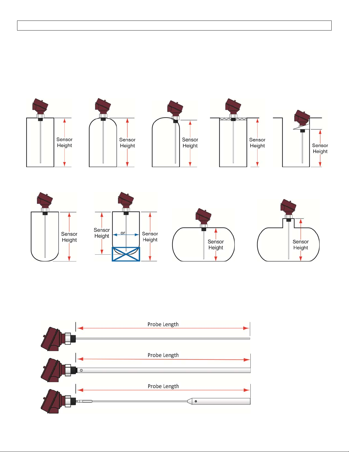
UnderstandingSensorHeight
ThisisacriticalsettingforLVRD10Series.SensorHeightdefinestheheightofthesensorabovethebottomof
thetank.Theheightvaluemusttakeintoaccounttheshapeofthetankandanyrisers,fittings,structuresor
extensions associated with the tank or the installation (see examplesbelow).Thereferencepointfor
definitionoftheSensorHeightisalwaysthebottomofthemountingnut.
Simple
Tank
ConeBottomRaises
SensorHeight
DomeTopRaises
SensorHeight(SH)
MountingFixture
RaisesSensorHeight
SensorOffCenter
ChangesSH
Simple
Tank
SimpleOpen
TopTank
SensorExtendsinto
SumpLoweringSH
RiserRaises
SensorHeight
UnderstandingProbeLength
Thereferencepointfordefinitionoftheprobelength[Length]isalwaysthebottomofthethreads[bottomof
thefeedthrough(seebelow)].Note:ThisisadifferentreferencelocationfromtheSensorHeight.Theprobe
Lengthisanimportantmechanicaldimensionwhichisneededtomakesuretheprobephysicallyfitsintothe
tankattheanticipatedmountinglocation.Probelengthhasaninfluenceontheactualmeasuringrangeofthe
sensor,butitisadifferentaspectofthesensor.
Note:SensorHeightandProbeLengthhavedifferentreferencepointsformeasurement.
RodProbe
(LVRD11Series)
CoaxialProbe
(LVRD12Series)
CableProbe
(LVRD13Series)
10
Page 11
GETTINGSTARTED SectionTwo
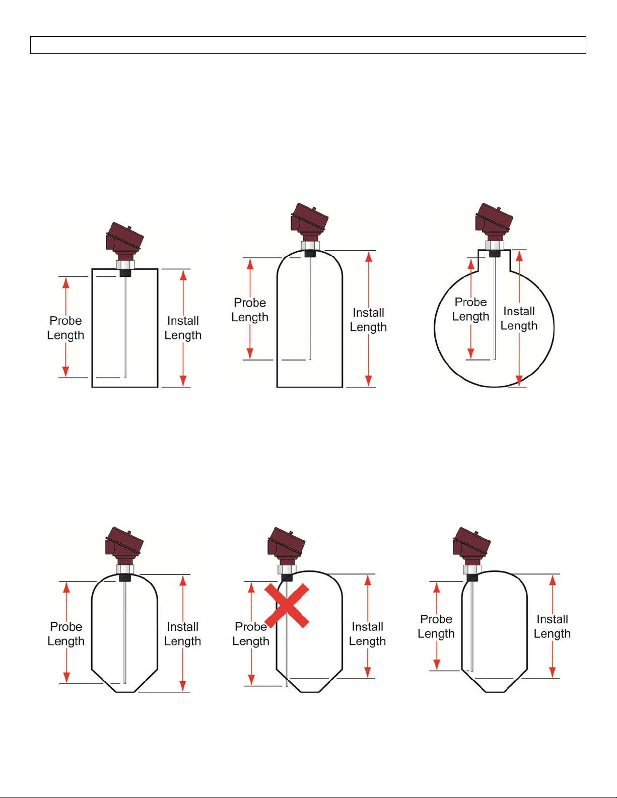
UnderstandingInstallLocationLength
Measurethespacebelowtheactualinstallationlocationforthesensor.Thisdistance(installlength)mustbe
greaterthantheprobelength.Inmanytanks,theinstalllengthcorrespondstotheheightofthetank.With
dometop,conebottomandhorizontaltanks,includetheaddedheightofthecurvedsurface.Besuretotake
intoaccounttheheightoffittings,risers,tankflatsetc.whichmaybeaddedforinstallation.Alloftheabove
canraisethebottomoftheprobehigherinthetankthanwhatwasoriginallyexpectedresultinginareduced
lowestlevelofmeasurement(seeMeasurementRange).
TankwithFlatTop
&FlatBottom
DomeTopsandConeBottoms
ThelocationofanLVRD10Seriesinstalledalongthetopofadome top tank may have an effect on the
installationofthesensor.Besuretomeasurefromtheactualpoint ofinstallation. Roundor conebottom
tankswillreducetheinstallheightavailable,dependingoninstalllocation.Ifthisoccurs,eitherthesensorcan
beraisedusingfittings(seeAddingaRisertoAvoidCuttingtheProbe)ortheprobe’slengthmaybereduced
bycuttingtheprobe(seeCuttingtheProbeinSection7).
TankwithDomeTop
&FlatBottom
Horizontal
Tank
InstallHeight>
ProbeLength
11
InstallHeight<
ProbeLength
InstallHeight>
ProbeLength
Page 12
GETTINGSTARTED SectionTwo
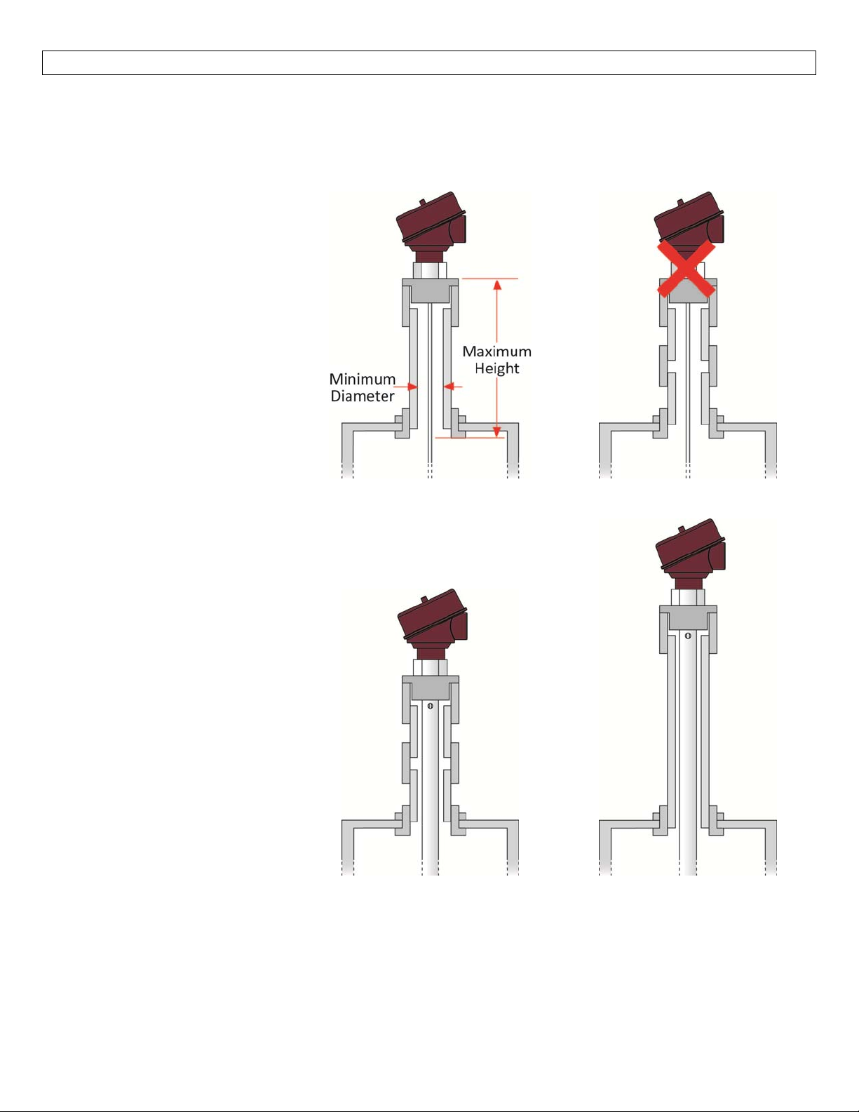
AddingaRisertoAvoidCuttingtheProbe
Insomeconditions,arisermaybeaddedtoavoidcuttingtheprobe.
RodandCableProbes
WiththeRodandCableversionsof
theprobe,themaximumheightfor
the riser is 12” (300mm). The
minimum diameter of the riser is
2”(50mm).Therisermustbe
metallic in construction using the
least number of fittings
/connections. Note:AnEmpty
SignalScanisarequirementso
that the EchoWave® can eliminate
the odd geometry created by the
riser.
Leastnumberoffittings
ToomanyFittings
CoaxialProbes
Withthecoaxialprobe,thereisno
maximumriserheightorminimum
riserdiameter.Thisisbecausethe
coaxial shield isolates the physical
changes to the installation from
thesensor’senergysignal.Inboth
examples,theenergysignalcannot
see any changes to the
fitting/connections or from being
installed in an extension that
exceeds the maximum height for
rodandcableprobes.
12
Page 13
GETTINGSTARTED SectionTwo
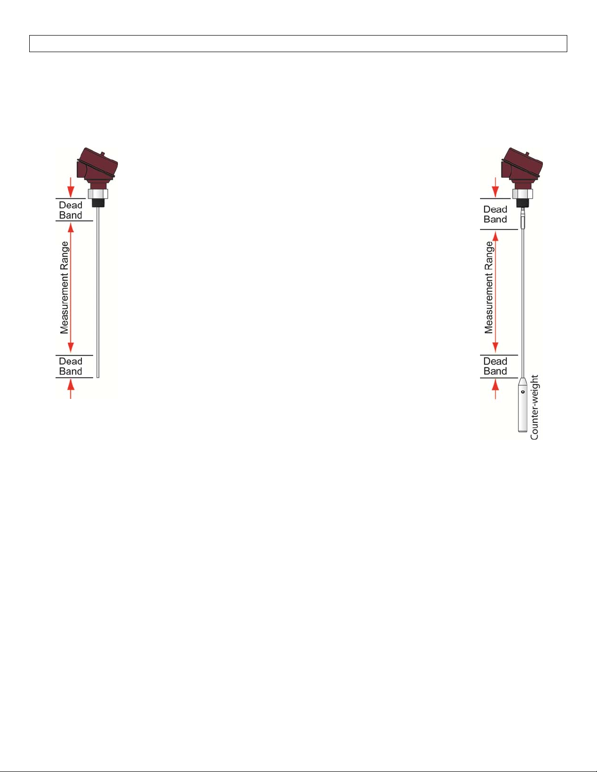
UnderstandingMeasurementRange
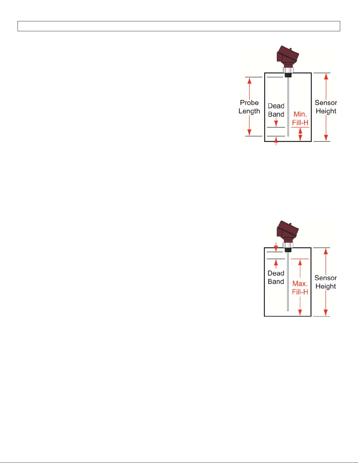
LVRD10Seriesleveltransmittershavesmall dead bandareasat boththetopandbottomoftheprobe.Itis
duetothepresenceofunavoidablesignaldisturbancesatbothendsoftheprobe.Inthesedeadbandareas
the measurementsare non‐linearor have reducedaccuracy. Therefore,itisnotrecommendedtoactually
measurelevelwithinthosedeadbandareas.Theirlengthdependsontheprobetypeandthereflectivity(i.e.
dielectricconstant)oftheliquidtobemeasured.
TheMeasurementRangeofLVRD10seriesextendsbetweenthetopand
bottomdeadbandareas;thisistheareainwhichasensorwillhavethe
specified measurement performance. It is recommended that the
maximumand minimumlevels to bemeasured inthetank areactually
within theMeasurement Range ofthe sensor. The span betweenthe
lower range value [4mA] and the upper range value [20mA] of the
current output is proportionally equal from 0 to 100% of your
continuouslevelmeasurementreading.Itisrecommendedthatthe
span between these two range values stays within the Measurement
Range.
The[TopDeadBand],closesttothethreads,issetto4”(100mm).This
ismeasuredfromthebottomofthenutdowntotheprobe.Thisis
consistent forall styles of probe. Note: the measurement location for
the Top Dead Band is different to the measurement location for the
probelength.
The [BottomDead Band],closesttotheendoftheprobe,issetto2”
(50mm).Thisismeasuredfromtheendoftheprobeonrodandcoaxial
probes.Forcableprobes,itismeasuredfromthetopofthecounter‐
weight.Thecounter‐weightmustbeincludedwiththedeadbandasthe
sensor’sinactivearea.
13
Page 14
GETTINGSTARTED SectionTwo
UnderstandingMinimumFill‐Height(puttingitalltogether)
LVRD10SerieshasaMinimumFill‐Height(Min.Fill‐H),whichismeasured
fromthebottomofthetanktothetopoftheBottomDeadBand.As
shippedfromthefactory,Min.Fill‐Hiswherethe4mAcurrentislocated
andisthelowestpointontheprobewherethesensorcandetectaliquid
level.Anypoint belowthis positionwill stopat4mA. The Min.Fill‐His
influenced by the Sensor Height (SH), Probe Length (P), Height of the
Threads[0.65”(16.5mm)]andBottomDeadBand.
Min.Fill‐H=(SH)–[0.65”(16.5mm)]–(P)+(BottomDeadBand)
Withacableprobe,includetheheightofthecounter‐weight.
SwitchoutputtovolumetricwillallowMin.Fill‐Htobesetto(0).
Ifthe4‐20mAoutputisreversed(20mAatbottomand4mAat
top),thenthelevelwillmaxoutat20mAwhenthelevelfallsbelowtheMin.Fill‐H.
Note:Becauseofthebottomdeadband,theMinimumFill‐Heightcanneverbeattheendoftheprobe.
Note: The configuration ofthe sensor (Distanceor Volume) will affect the current output at Minimum Fill‐
Height.UponselectingDistance,thecurrentwillbesetto4mAatMinFill‐H.However,uponselectingvolume,
the current at Min Fill‐H will be the calculated based upon 4mA being set at the bottom of the tank [see
Distance(HeightofLiquid)vs.VolumeofLiquid].
UnderstandingMaximumFill‐Height
LVRD10 Serieshas a MaximumFill‐Height (Max. Fill‐H),which ismeasuredfrom
thebottomofthetanktotheTopDeadBand.Asshippedfromthefactory,Max.
Fill‐H definesthe 20mAcurrent depicting thehighest pointon the probewhere
thesensor detectsliquid level.Anypointabovethisposition willstop at20mA.
The Max. Fill‐H is influenced by the Sensor Height (SH), HeightoftheThreads
[0.65”(16.5mm)]andTopDeadBand.
Max.Fill‐H=(SH)–[0.65”(16.5mm)]–(TopDeadBand)
TheMax.Fill‐Hmaybedecreasedtolowerthe20mAlocation,butit
cannotberaisedaboveitsoriginalsetting.
Ifthe4‐20mAoutputisreversed(20mAatbottomand4mAattop),then
thelevelwillmaxoutat4mAwhenthelevelrisesabovetheMax.Fill‐H.
Note:Becauseofthetopdeadband,theMaximumFill‐Heightcanneverbeatthebottomofthethreads.
14
Page 15
GETTINGSTARTED SectionTwo
Distance(HeightofLiquid)vs.VolumeofLiquid
Withthe LVCN414‐SWsoftware,the LVRD10seriescan beconfigured tooperateas adevicethat reads the
distance(heightofliquid) or volumeof aliquid. Thelocation ofthe emptycurrentwilladjustdependingon
which configuration method is selected. Note:The empty(4mA) location is placed at a different location
baseduponselectingliquidheightorliquidvolume.
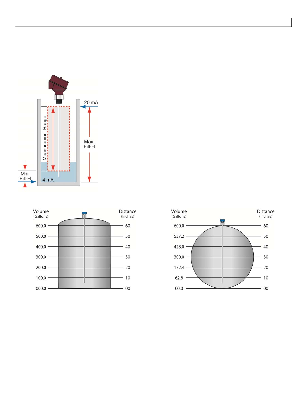
Distance(HeightofLiquid):WhentheLVRD10Seriesisconfiguredto
readtheheightoftheliquid,thedefaultforthesensorEmptywillbeat
the bottom of the measurement range (end of the probe minus the
bottomdeadband).Thisiswhere4mAwillbeset.Thedefaultfor
sensor Full will be at the top of the measurement range (Top Dead
Band),where 20mA willbeset. The20mAcanbe setbytheMaximum
Fill‐Height.
Volume of Liquid:WhentheLVRD10seriesisconfiguredtoreadthe
volumeofliquid,theoutputwilltrackthevolumeofthetankasthelevel
increasesanddecreases.LikeDistance, theEmptyand Fullsettingswill
defaulttothelowandhighendoftheMeasurementRange.The
location of the 20 mA can be adjusted with the Maximum Fill‐Height
settings. However, the shape of the tank can influence the current
output,dependinguponthetankbeinglinearornon‐linear(seebelow).
LinearTankExample
Note: In the above illustration, 10” of liquid will
always be equal to 100 gallons of liquid (1” = 10
gallons).
Non‐LinearTankExample
Note: In the aboveillustration, 1”of liquiddoes not
equal10gallons.The10”atthebottomrepresentsa
rise of 62.8gallons. As a changebetween 10” and
20”representsanincreaseof109.6gallons(i.e.172.4
gallons–62.8gallons).
15
Page 16
INSTALLATION SectionThree
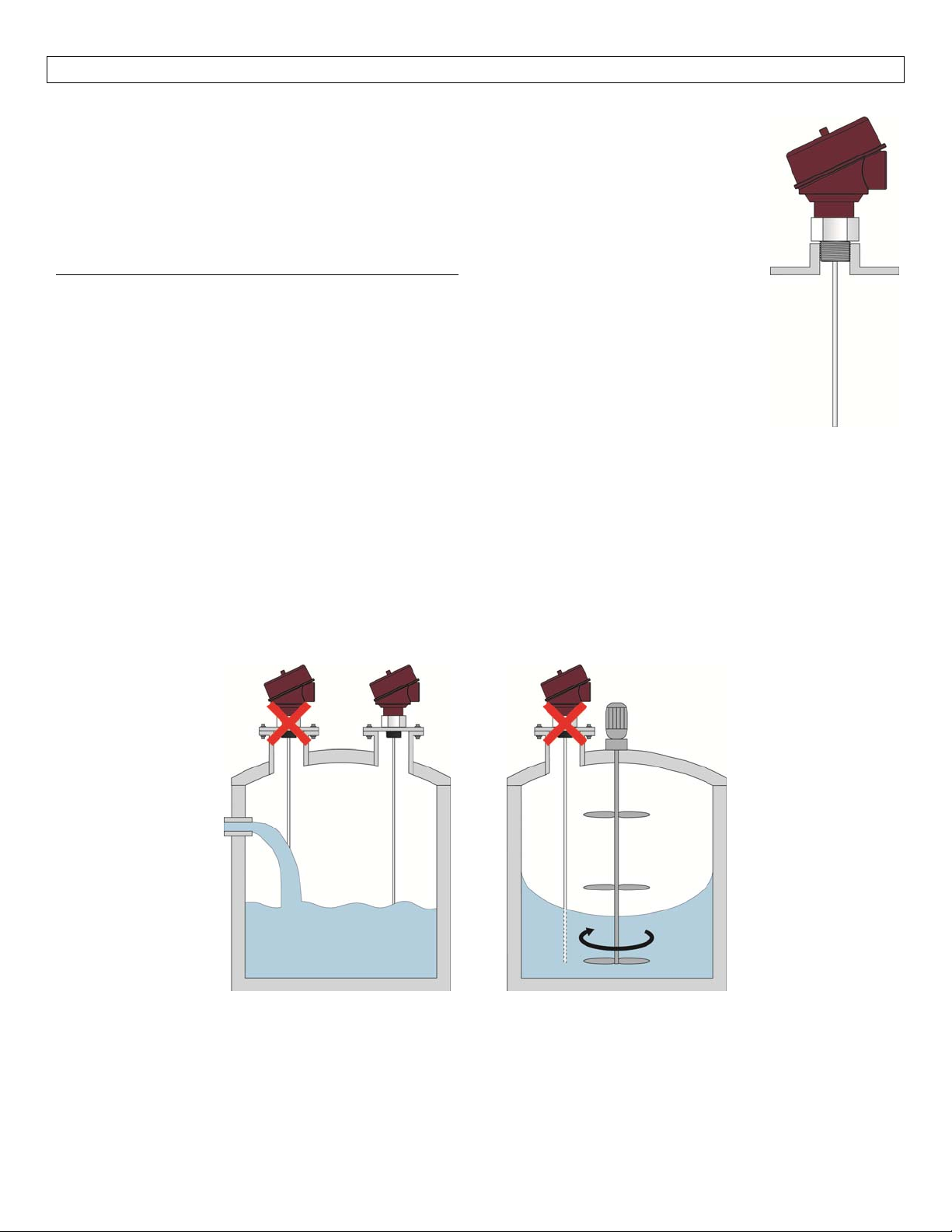
LVRD10 series is mounted vertically into the tank via its connectionthread.Itisthen
screweddirectlyintoastandardthreadedtankconnection,i.e.tankadapter,bushing,weld‐
insocket,oritcanbescrewedintoaflangewhichisconnectedtoatanknozzle.
Thesensorshouldnotbeweldeddirectlyintothetank.Neithershouldflangesbewelded
ontothesensor.WeldingonthemetalpartsofLVRD10Serieswillcauseseriousdamageto
thetransmitter.
DonotliftorhandletheLVRD10seriesbyitsprobe
probeconnection.LVRD10Seriesshouldbehandledbythehexagonorthelowersectionof
thehousing.Donotscrewinthesensorbyitshousing.Itshouldbetightenedonlyviaits
hexagon(wrenchsize32mm).
Theend userhas toensure propersealing ofthe sensorconnection; basedupon process
conditions, i.e. temperature, pressure and resistance against the process liquid’s
atmosphere.
ForNPTthreadconnections,pressure‐tightjointsrequireasealantdirectlyonthethreads.
Inthecasethatthesensorisdeliveredwithadetachedprobe(cableversiononly),attachtheprobeontothe
smallthreadedstudbelowthehexagon.Makesuretoavoidcrossthreadingormisaligningthethreads.
MountingConsiderations
Theprobesshouldbeinstalledsothattheyarenotdirectlyimpactedbyliquidsflowingoutofthefillinginlet.
They should neither touchnor swaytowards otherobjects insidethetankorthetank/nozzlewalls;e.g.by
agitator or mixer swirls. In applications with very strong fluid movements which can also cause excessive
lateral force on the probe, it is recommended to anchor the probe. The anchoring fixtures are end user
supplied.
:thiswillcauseexcessivestressonthe
16
Page 17
INSTALLATION SectionThree
MountingConsiderations(continued)
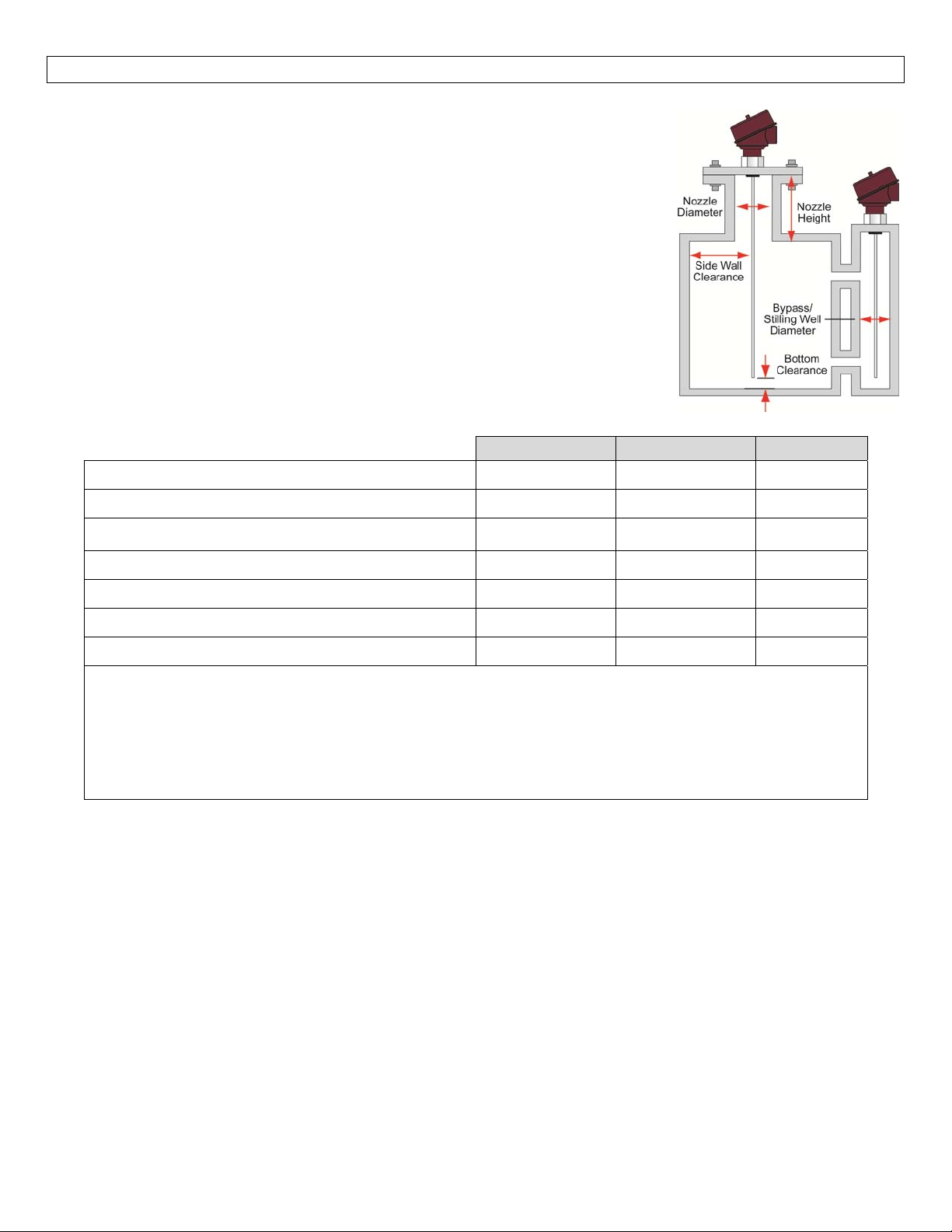
Therodandcable probesare suitablefor avery widerange ofapplications in
liquids.However,thesignalhasawiderdetectionradiusaroundtherod/cable.
Therefore,itismoreresponsive formeasurementsignaldisturbancesthatare
overcome by a few Mounting Considerations (see below) as well as simple
configurationadjustmentstothesensor.Inmostcasesitisenoughtoactivate
and utilize the powerful LVRD10 series empty signal scan feature.Itworks
mostefficiently onstationaryinterference targets liketalland narrownozzles
orclose‐byobjects.
In case a non‐stationary interference target is close to the rod probe, like slowly
rotating agitator blades causing problems with the measurement,itis
recommendedtousethecoaxialprobe.Inanycase,therodandcableprobes
shouldnevergetindirectcontactwiththetank/nozzlewallorotherobjectsinthe
tank.
nozzlediameter >2”(50mm) >2”(50mm) +
Rod Cable Coaxial
(1)
nozzleheight <12”(300mm) <12”(300mm) +
clearancetotankwallorotherinternalobjects >4”(100mm) >4”(100mm)
+
clearancebetweenprobeendandtankbottom >0.1”(2mm) >0.1”(2mm) +
diameterofbypasschamber/stillingwell >1”(25mm) >1”(25mm) +
(2)
metallictankorbelowgradeconcretebasin + + +
Non‐metallicorplastictank NR NR +
+ =recommended
(1)
+
=enoughdiametertofitinthecoaxialtube(0.843”/21.3mm)
(2)
+
=enoughdiametertofitinthecoaxialtube(0.843”/21.3mm)withallocatedroomaroundthe
probeforliquidflowthroughthebypasschamber/stillingwell
NR =NotRecommended
TherodprobeisalsotherecommendedprobetypeformountingtheLVRD10seriesintobypasschambersor
stillingwells.Inthiscase,plasticcenteringspacersareneededtopreventtheprobefromcontactingthewall.
The cable probe is recommended for installations in tall tanks where limited installation headroom is
available.Itsperformancecharacteristicsandmountingconsiderationsaresimilartotherodprobe.
Thecoaxialprobedoesnothaverestrictionsregardingmountingposition,tankconnection,proximitytothetank
walland other objects inside thetank. The coaxialprobe isrecommendedfor installingLVRD10 seriesinto a
non‐metallictankoropenpit
17
Page 18
INSTALLATION SectionThree
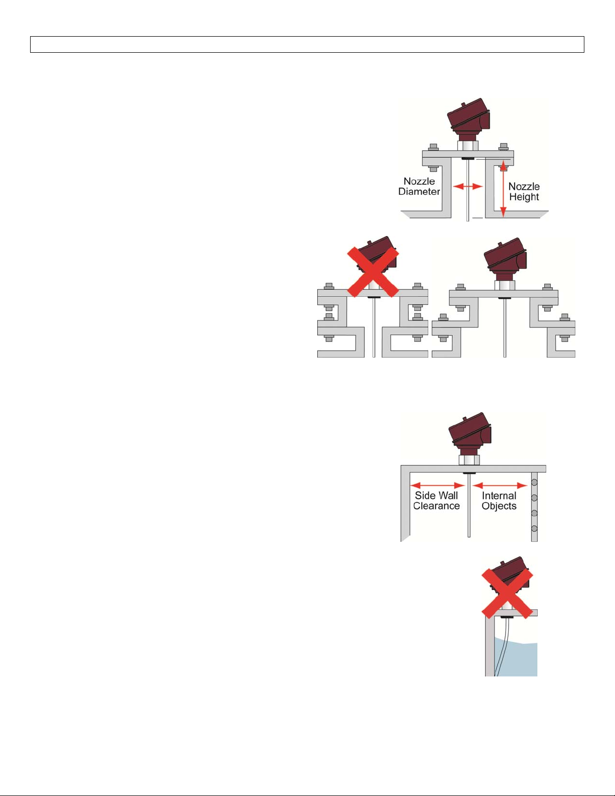
InstallationTips
TallandNarrowRisers
Rod and Cable probescan beinstalled intall and narrowrisers
underthefollowingcriteria:
NozzleDiametermustbe>2”(50mm),
NozzleHeightmustbe<12”(300mm),
Risermustbemetallic,
Anemptysignalscanisrequiredafterinstallation.
Coaxialprobesarenotaffectedbytallandnarrowrisers.
DifficultTankorRiserGeometries
RodandCableprobesmustfollowthecriteriabelow:
Tall and Narrow Risers criteria must be
followed,
Nozzlediameterremainsthesamediameter,
NozzleDiameterdoesnotdecrease,
NozzleDiametermaygetlarger,butaempty
signalscanisrequired.
Coaxialprobesarenotaffectedbytheshapeofthe
tankorthegeometryofthenozzleastheaboveisnot
applicable.
ClosetoSideWallorInternalObstructions
RodandCableprobesmustfollowthecriteriabelow:
>4”(100mm)fromthesidewall,
>4”(100mm)fromanyobjectsorobstructionswithinthe
tank,
Aemptysignalscanmayberequiredafterinstallation.
Coaxialprobesarenotaffectedbythedistancefromtheside
wallorfromotherobjects/obstructionswithinthetank.
MovingProbe
RodandCableprobesmustfollowthecriteriabelow:
Avoid applications where the movement of the tank will cause the
probetoswingortouchobjectsandobstructionsinthetankortheside
wallofthetank.
Avoidapplicationswherethetankistruck/vehiclemounted.
Coaxialprobesarenotaffectedbythemovementofliquidwithina stationary
tank.
18
Page 19
INSTALLATION SectionThree
InstallationTips(continued)
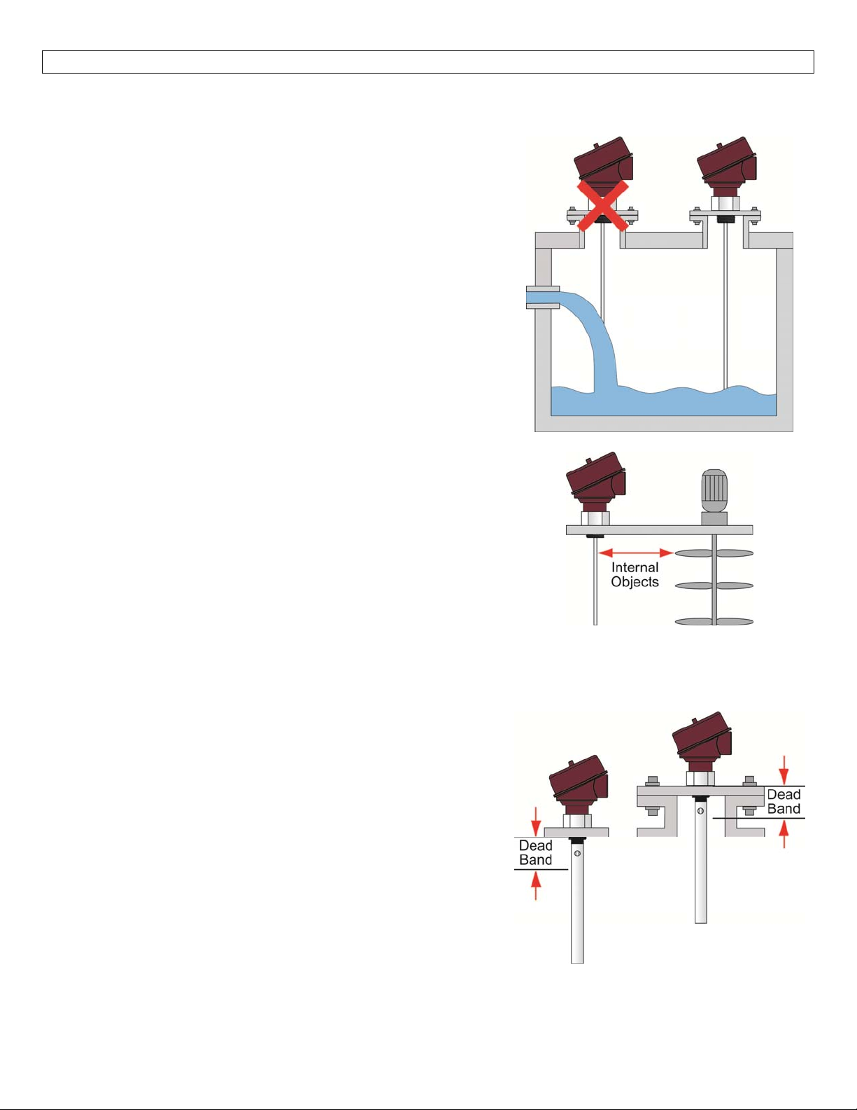
LiquidSpray
RodandCableprobesmustavoidanyliquidthatspraysorpours
ontotheprobe.
Coaxialprobes arenot affectedbyliquid sprayingon parts that
are above the liquid surface. However, avoid installing probe
whereliquidwillpourontotheprobe.
Non‐Stationaryobjects
RodandCableprobesfollowthecriteriabelow:
>4”(100mm)fromanyobjectsorobstructionswithinthe
tank,
Anemptysignalscanmayberequiredafterinstallation,
Non‐stationaryobjectsmust notbemovingwhen empty
signalscanispreformed.
Coaxial probes are not affected by the movement of non‐
stationaryobjects,suchasmixerbladesorpumpliftingchains.
Note:All probes(rod, cableandcoaxial) canbe affectedbyany
liquidvortexcreatedbyamixer.
Measurementreadingsattheverytoporbottomofthetank
Rod and Cable probes do not have the outer tube and must
adheretoallmountingrequirements,specifically:
>4”(100mm)fromanyobjectsorobstructionswithinthe
tank,includingthebottomofthetank,
Criteriafordifficulttankorrisergeometriesmustbe
followed.
Coaxialprobescaneasilybemechanicallymountedtoensurethe
measurementofliquiduptoafulloremptytank.Becausethe
coaxial is encased within the outer tube, the sensor is self‐
containedsootherobjectsorobstructionsarenotanissue.This
makesraisingorloweringthesensorsimpleandstraightforth.
19
Page 20
INSTALLATION SectionThree
InstallationTips(continued)
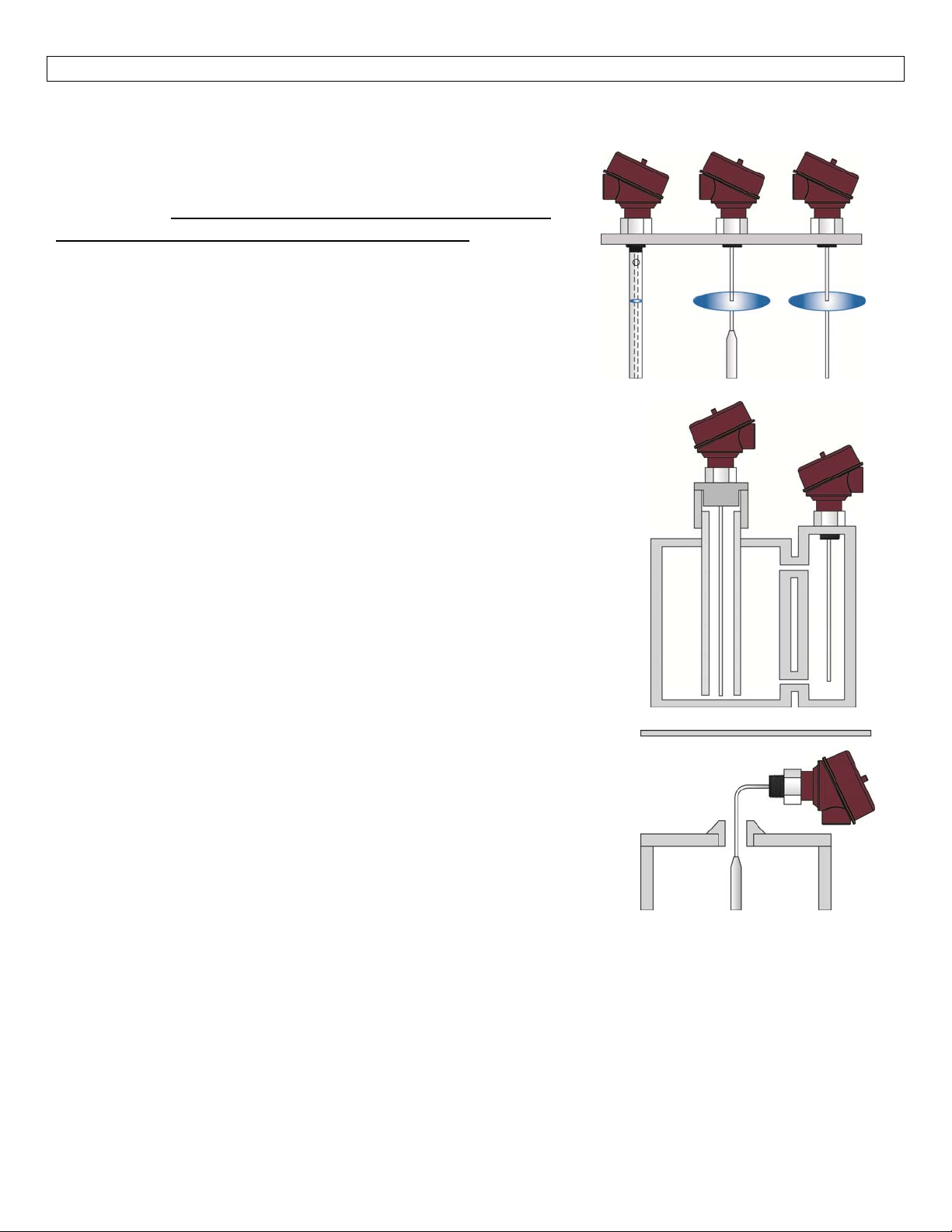
Non‐metallictanks
Unlike coaxial, rod and cable probes have no containment
mechanism.Thisenergymustbecontainedbythetankwall,
requiring that all rod and cable probe sensors be installed in
metallictanksorwithinbelowgradeconcretesumps.
Coaxial probes can be installed in any type of tank, including
non‐metallic tanks. This is because the outer tube acts as an
insulatorpreventing thesensor’s energyemanating beyondthe
probe.
StillingWells/BypassChambers
Installations within a stilling well or a bypass chamber are
recommendedwitharodprobe.Ametallicpipeisrequired.Acoaxial
probe can be used in a stilling well or bypass chamber if required.
Note:Neveruseacableprobewithinastillingwellorbypasschamber.
Makesurethattheprobedoesnotcomeinto contactwiththe
innerwallofthestillingwellorbypasschamber
o Non‐metallicspacersmayberequiredtokeeptheprobe
withinthecenterofthestillingwellorbypasschamber
Make sure the liquid is able to freely fill, empty and that no
residueremainswithinthestillingwellorbypasschamber.
Allothermountingcriteriamustbeobserved
Aemptysignalscanmayberequiredafterinstallation
Limitedheadroom
Wheninstallinginatankwherethereislimitedspaceabovethetopof
the tank, the cable probe is the recommended solution. The cable
probedesignallowsfortheprobetobeinstalledthroughasmallspace
abovethetank.
Therodandcoaxialprobes may beinstalled aslong as theprobes are
notdamagedorbentandaslongasthesensorisnotheldbytheprobe
(sensormustbeheldbythehead).
Allothermountingcriteriamustbeobserved.
20
Page 21
INSTALLATION SectionThree
InstallationTips(continued)
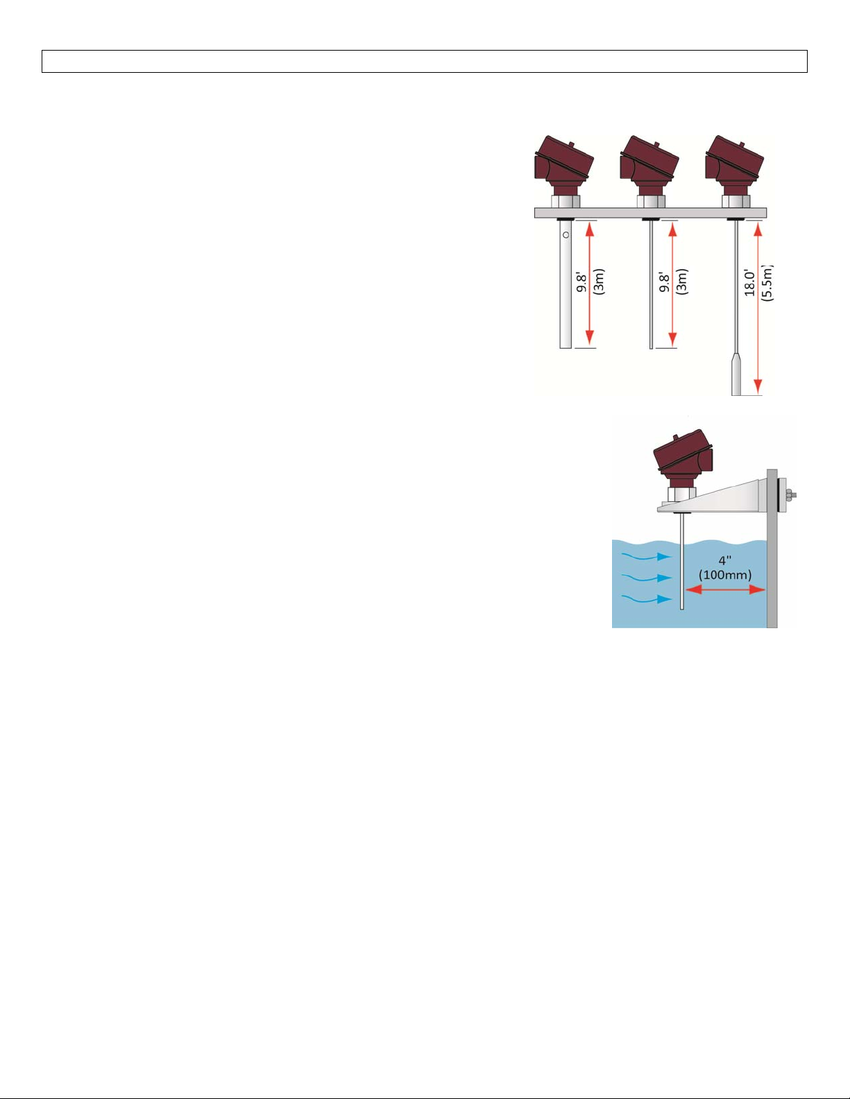
TallTanks
Therodandcoaxialprobeshaveamaximuminsertionlength of
9.8’(3m).Formetalorconcretetanksthataretaller/deeper,the
cableprobecanbeusedforlengthsupto18.0’(5.5m).
The maximum length is based from the bottom of the
threads.
o Note: the coaxial probe consists of a rod probe
with a metal outer tube installed around the
originalrod.Thebottomofthemountingthreads
areusedasthereferencepointformeasurement.
SideMountBrackets(LMV‐30Series)
Rodand Cable probescanbe installedwiththe side mountbracketunder the
followingcriteria:
The side wall or any object / obstructions do not come within 4”
(100mm)fromtheprobe
Anymovementof theliquid willnotcausethe probetoswinginto the
sidewalloranyobject/obstruction
Thetankmustbemetallicorabelowgradeconcretebasin
Anemptysignalscanmayberequiredafterinstallation
Ametalplateof6”indiametermayberequiredifthereisnorooftothe
tank/basin
Coaxialprobesarenotaffectedbythesidemountbracket.
ProbeTooLong
Forinformationoncuttingtheprobe,seeCuttingtheProbewithintheAppendix,Section7.
21
Page 22
WIRING SectionFour
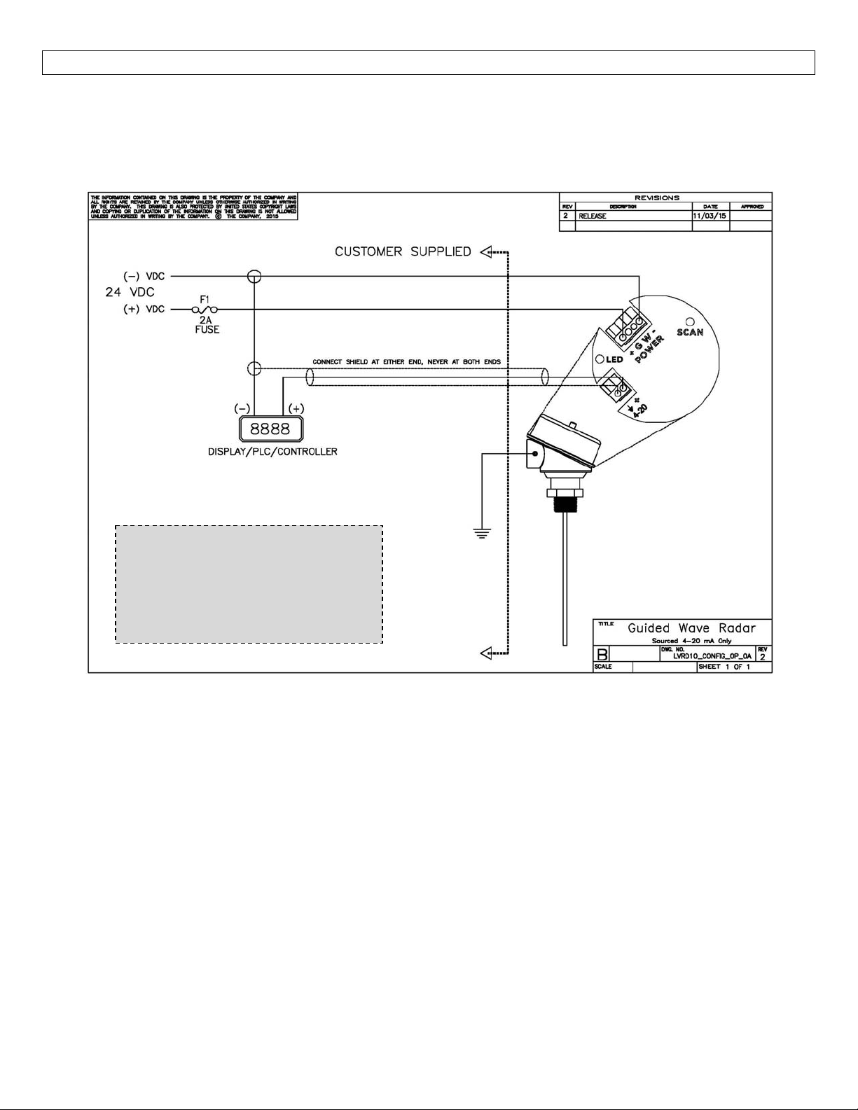
AnalogOutput(4‐20mA):TheanalogoutputoftheLVRD10Seriesisasourced4‐20mAcontrolcircuit.The
typicalwaytousethisfeatureistoconnectapositivesupplytothe(+)inputterminal,anegativesupplytothe
(‐)inputterminalandtoconnectthecurrentoutputoutofthe420(+)terminal.Thedevicethatacceptsthe4‐
20mAcurrentsignalmustreferencethesamenegativesupplylistedabove(seediagrambelow).
SampleWiringDiagram
Diagram will change based upon
the sensor’s configuration, use
LVCN414‐SW software to view
appropriatewiringdiagram.
ThecablingshouldbeshieldedandtwistedtominimizeEMIinterference.Itsshieldshouldbeconnectedateither
endandneverconnectedatbothends.Typically18to24gaugewireisusedinthisapplication.
GeneralNotesforelectricalconnections,usageandsafety:
Where personal safetyor significant property damagecan occurdue to a spill, theinstallation must
havearedundantbackupsafetysysteminstalled.
Wiringshouldalwaysbecompletedbyalicensedelectrician.
Protectthesensorfromexcessiveelectricalspikesbyisolatingthepower,wheneverpossible.
Supplyvoltageshouldneverexceed30VDC.
Makesurethatthepowersupplydoesnothaveacurrentmorethan2Aorthatthereis2Aratedfuse
intheelectricalcircuitthatenergizesthedevice.
Thesensormaterialsmustbechemicallycompatiblewiththeliquidstobemeasured.
Designafail‐safesystemforpossiblesensorand/orpowerfailure.
Neverusethesensorinenvironmentsclassifiedashazardous.
22
Page 23
WIRING SectionFour
WireConnections
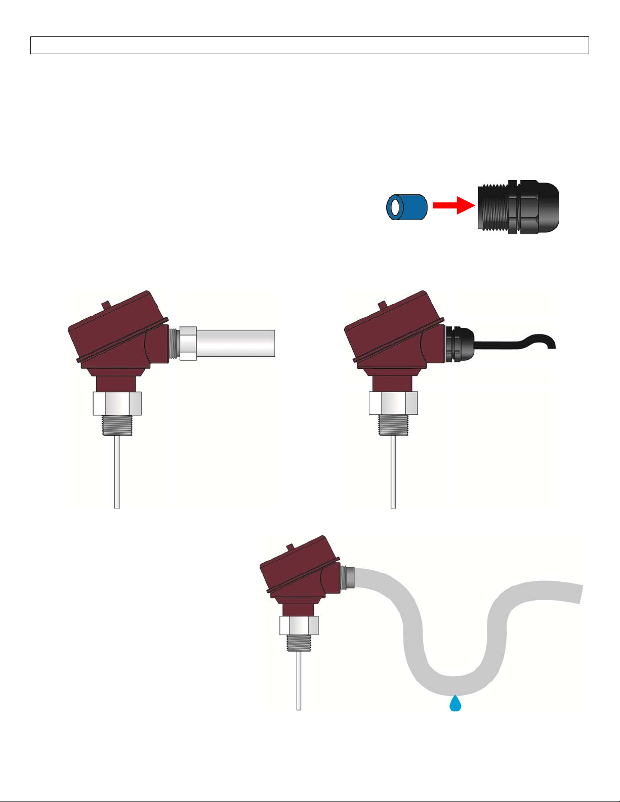
Thehousinghassinglecableentryandcanbeattachedtoscrewplugs,cordgripsorconduitwiththe½”NPT
thread. Note: the customer must confirm the suitability of those connectors for the specific application
requirementsandcabling;andreplace themwhen necessary. IP66‐ratedscrew plugsand cordgrips haveto
beproperlymountedandtightenedaround cableof suitabletypeanddiameterto ensure theIP66 rating of
thehousing.
Note:Aliquid‐tightcordgripandferritebeadareincludedwiththe
sensor(seeSpecificationSectionforcordgripdata).
Note: Always include the ferrite bed when using the cord grip or
whenusingnon‐metallicconduit.
Note:Alwaysshieldthesignalwireperinstructionsonthewiringdiagram.
ConduitConnection CableGland(LiquidTight)w/Washer
FerriteBead
Liquid‐TightCordgrip
AvoidCondensationintheConduit
You can give your instrument additional
protection against moisture penetration
byleadingtheconduitconnectionorcable
downward in front of the cable entry.
Condensationin theconduit will thusnot
enterthesensorenclosure.
23
Page 24
WIRING SectionFour
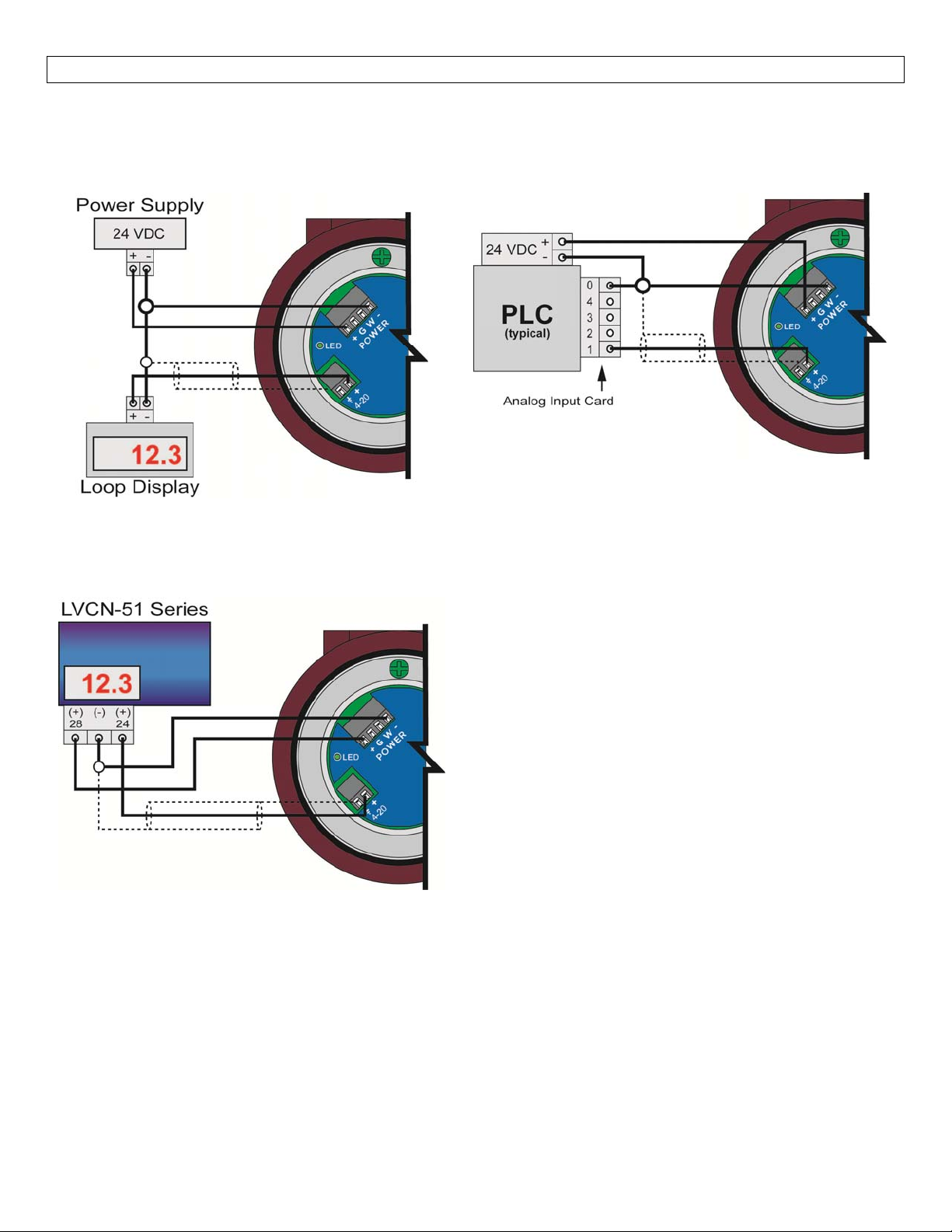
CommonWiringtoDisplay,Controllers&PLC’s(continued)
GenericLoop
PoweredDisplay
DataPoint™LVCN‐51Series
LevelController
JWBmode
GenericPLC
Note:LVCN‐51shippedfromfactorywithjumperinJWAmode.JumpermustbeswitchedtoJWBmodefor
operationwiththeLVRD10Series.
Note:4‐20mAsignalwirerequiresshielding(powersupplywiresmayusethesameshieldingasthesignal
wire).Shieldwirecanbeconnectedateitherend.Neverconnectshieldwireatbothends.
Note:LVRD10Seriesisa3‐wiresensorandshouldneverbetreatedasa2‐wirelooppowereddevice.Follow
theillustrationsaboveforwiringtothemostcommondevices.
24
Page 25
CONFIGURATION SectionFive
LVRD10SeriesisconfiguredthroughafreePCsoftwareprogram(LVCN414‐SW,version6.5 orgreater). The
software is a free download from Omega Engineering®’s website. You must download and install the
softwarepriortopluggingintheUSB®Fob.
Pleasegotohttp://www.omega.com/ftp.
ClickonFlow,Level,pH,Environmental,andPressureSectionandpressonProducts.
Selecttheinstaller–LVCN414InstallerVerXpXX.zip.
o Thiswilldownloadtheinstallerontoyourcomputer.
o Oncecompleted,runtheinstaller.
LVCN414‐SWSoftwareSystemRequirements
Windows®2000,XP,Vista,7,8
32or64‐bitsystem
1USB®2.0port
10mBharddrivespace
256mBRAM
Internetconnection
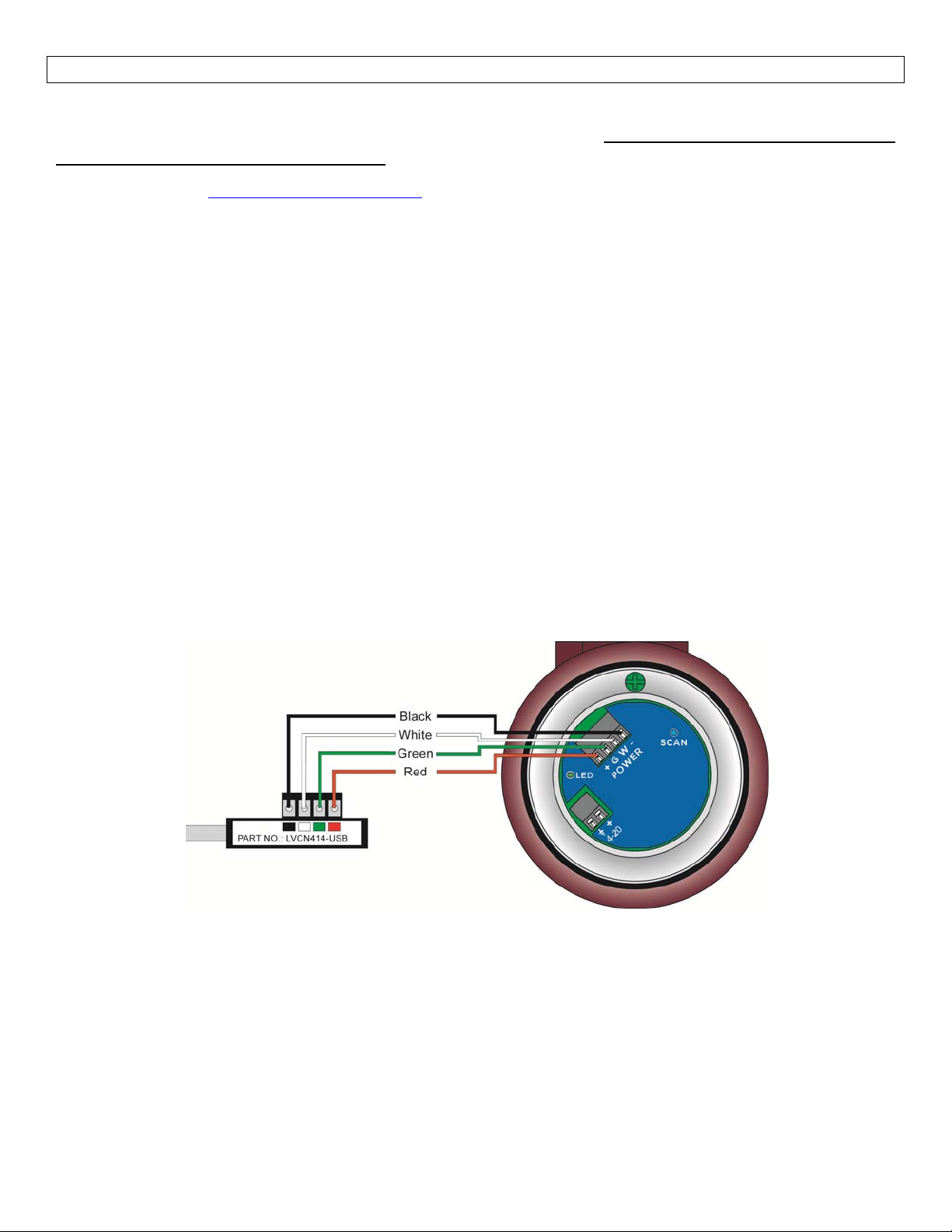
USB®FobInterface:LVRD10SeriescommunicateswiththeLVCN414‐SWsoftwarethroughaUSB®interface
calledaFob. Before pluggingyourFobinto yourcomputer’sUSB®port, besurethatyou have installedthe
softwareontoyourcomputer.
Connect the red, green, white and black terminals on the Fob to the corresponding terminals within the
LVRD10Series.TightenthescrewsontheterminalsandplugyourFobintotheUSB®portofyourcomputer.
WiringisidenticalforallseriesofLVRD10Series
The maximumcable distance betweenthe computer andLVRD10 Seriesis15’.Thisonlyapplieswhen
configuringtheLVRD10Series.
Once LVRD10 Series is configured and prior to installation, disconnect all wires from the center two
terminalstopreventashortoftheconfigurationcircuit
Note:WhenusingtheFob,donotaddVDCpower.TheFob,whenconnectedtothecomputer,willprovide
therequiredpowertotheLVRD10Series.
25
Page 26
CONFIGURATION SectionFive
With LVRD10 Series connected to your computer, open the LVCN414‐SW software by clicking on the
software’sicon.FollowstepsAtoDtoconfigurethetransmitter.Click“Help”inthelowerrighthandcorner
andopenthehelpmenu for additionalinstructions onthe software.Ifyouneedadditionalassistanceusing
theLVCN414‐SWsoftware,pleasecontactanOmegaEngineering®applicationengineer.
ConfiguringLVRD10SerieswiththeLVCN414‐SWSoftware
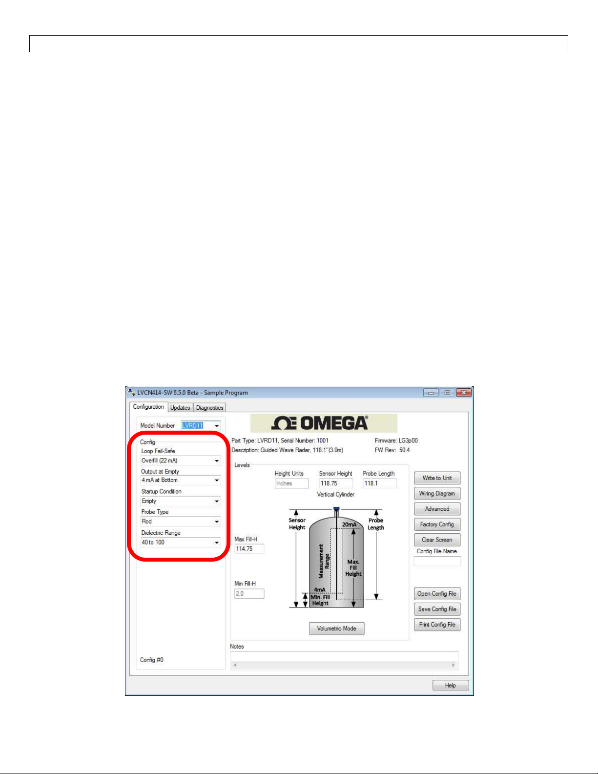
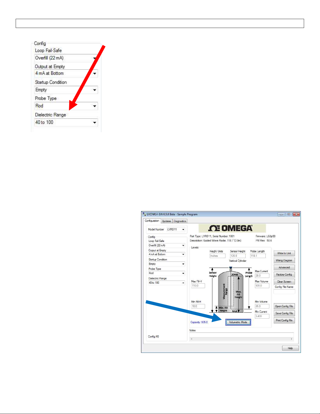
A. SensorConfiguration
1. ConfiguresLoopFail‐Safe,OutputatEmpty,StartupCondition&DielectricRangeforthesensor.
2. AlsoconfirmProbeType(Rod,CoaxialorCable)inthepulldownmenu.
B. DimensionalEntry
1. DistanceMode(default)
i. Basicinformationforoperation(SensorHeight,ProbeLength&MaximumFill‐Height).
2. VolumetricMode
i. Definesthe shape ofthe tankaswell as thedimensionalinformation forthe tankwith
respecttothesensor’slocationonthetank.
C. TankLevelConfirmation
1. Confirmthevaluesareaccuratefortheapplication.
D. WritetoUnit
1. Uploadsconfigurationintothesensor.
2. Accesstoacustomerwiringdiagramspecifictotherelayconfiguration.
A.SensorConfiguration:
26
Page 27
CONFIGURATION SectionFive
B.DimensionalEntry:
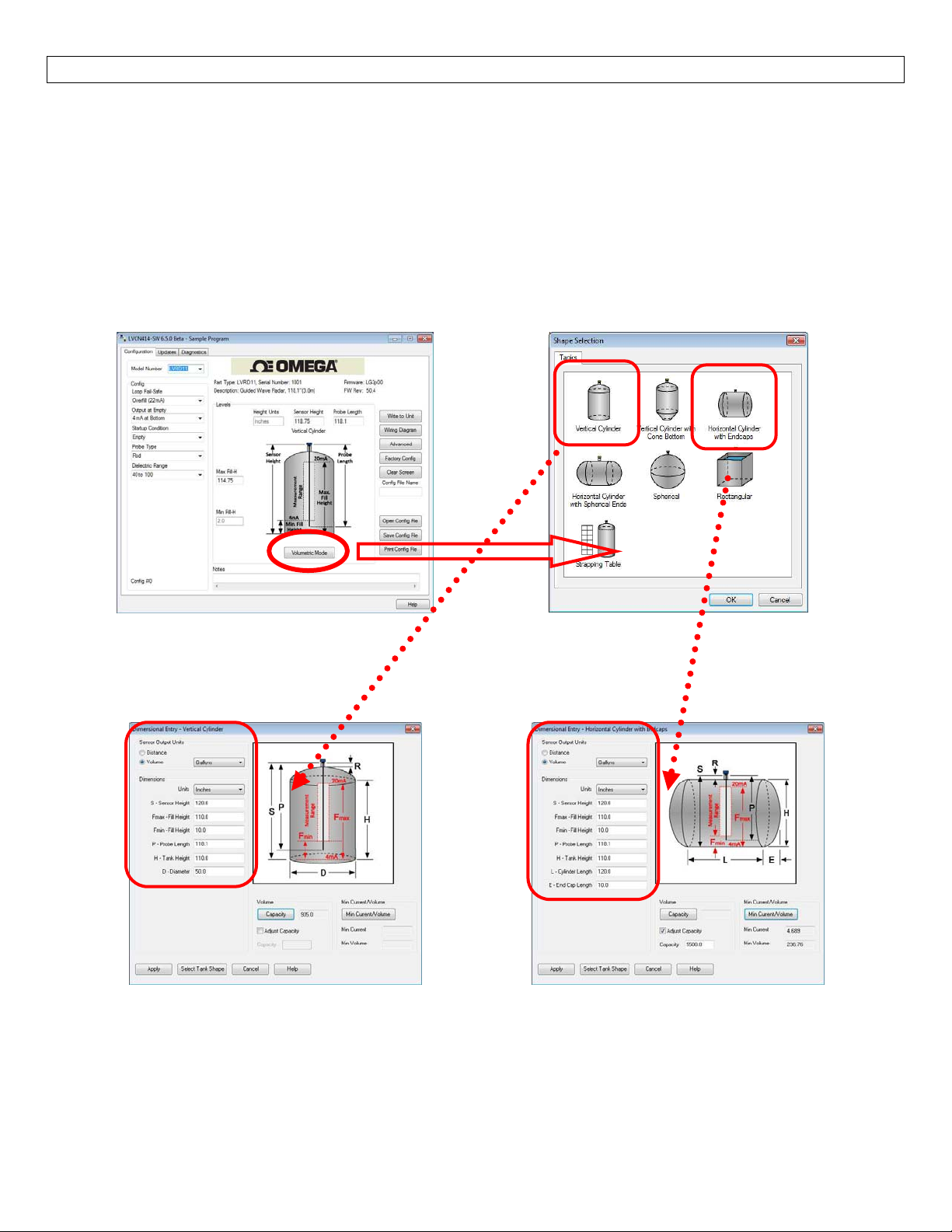
1.DistanceMode (default):Outputof sensorisbasedon thedistance(heightof liquid)inthetank.
Anychangeinliquidlevelwill reflect linearlyto the currentoutput. Note: Mostapplicationswill fall
intothiscategory.ThethreesettingsyoumustenterforDistance Mode are Sensor Height, Probe
LengthandMaximumFill‐Height.Allthreesettingscanbeenteredonthemainconfigurationscreen.
2.Volumetric Mode: Allowstheendusertoswitchfromthe standarddistanceoutput toanoutput
based upon the volumetric shape of the tank. In Volumetric Mode, the shape of the tank is first
selectedfollowedbytheentryof dimensional information for thetankwithrespecttothesensor’s
locationonthetank.
Enter theoperational dimensionsfor the sensorand tank withinthedefinedapplication.Allofthe
showndimensionsarerequiredandwilladjustdependingontankshapewhethertheoperationisfor
volumeordistance.PressApplywheninformationiscompleted.
Note:While in Volumetric Mode, the sensor may be switched between Distance and Volumetric
outputs (under Sensor Output Units). When Distance is selectedtheunitsareinches,cm,feetor
meters. When Volume is selected, the units are Gallons or Liters.Thetypeofconfiguration
output (Volumetricor Distance) and themeasured units may bechanged under Sensor Output
Units.
27
Page 28
CONFIGURATION SectionFive
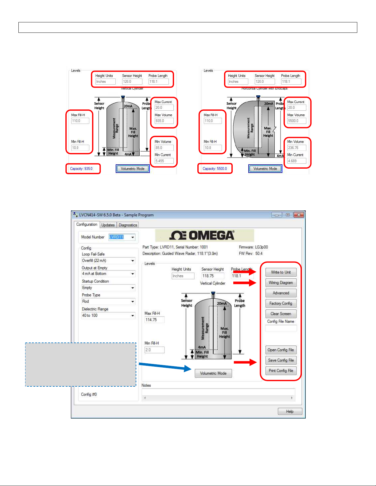
D. Tank Level Confirmation: Verify the Height Units, Sensor Height, Probe Length, Maximum Fill‐Height,
Minimum Fill‐Height, Capacity as well as the Max./Min. Volume and Max./Min. Current. All values were
calculatedinthepreviousDimensionalEntrywindow.Toadjustthesesettings,clickonVolumetricModes.
E.WritetoUnit–Thisoperationuploadsconfigurationintothesensor.Otherfeaturesinthesectioninclude
providingacustomwiringdiagramspecifictothesignaloutputandsavingtheconfigurationfiletoyourhard
drive.
VolumetricSensorOutput
TheVolumetricModebuttonwill
be highlighted in Blue when a
volumeoutputisselected.
28
Page 29
EMPTYSIGNALSCAN SectionSix
EmptySignalScan
The empty signal Scan is a powerful disturbance signal suppression feature of LVRD10 Series. The sensor
scans its entire probe length for any disturbance/interference signals within the application that could
potentially be misinterpreted as level readings by memorizing and suppressing them during operation.
Therefore,theLVRD10seriesonlyrecognizestheactuallevelsignalscausedbytheliquidbeingmeasured.
Theemptysignalscanisintendedfortherod&cableprobe,sinceitssignalhasawiderdetection
radiusaroundtheprobemakingitmoreresponsiveformeasurementsignaldisturbances.
Theemptysignal scanworks mostefficientlyonstationaryinterference targetslike talland narrowrisersor
close‐byobjects/obstructions. To enablean emptysignal scan,theLVRD10serieshastobemountedinits
finalposition.Thetankhastobecompletelyempty.Thiswill ensurea reliableidentification ofthe actual
disturbancesignals only.Incasetherearenon‐stationaryinterferencetargetsclosetotherodprobe(slowly
rotatingagitatorbladesorstreamsofliquidfillingintothetank),itisrecommendedtousethecoaxialprobe.
ActivateEmptySignalScan
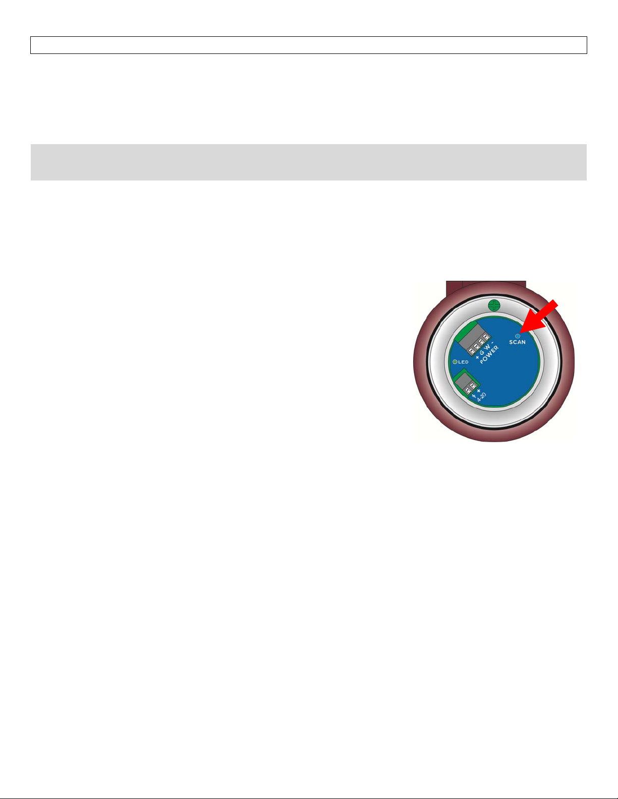
WhenLVRD10Seriesisshipped,thisfeatureisdeactivated.Toinitiatea
emptysignalscan,usethefollowinginstructions:
1. Make sure theLVRD10 series is installedin its final installation
position.
2. Makesuretheliquidisatitslowestlevel(empty).
a. Performing an empty signal scan when the tank is not
empty will create an incorrect scan. It can affect the
sensorsperformanceespeciallyatliquidlevelsbelowthe
emptysignalscantanklevel.
3. PressandholdtheSCANbuttonfor6seconds.
a. The LED will begin to flash Orange indicating theempty
signalscanhasbegun,releasethebutton.
b. Uponcompletionoftheemptyscan,asolidgreenLEDwillreturn
c. Iftheemptyscanisnotsuccessful.TheLEDwillflashred
EraseEmptySignalScan
Ifthereisaneedtoeraseorturnofftheemptysignalscan,performthefollowing:Firstremovepowertothe
LVRD10 Series. Next,hold down theSCAN button while applying powerto the sensor. When the LVRD10
seriesacquiresasignal(LEDwillflashGreen),thedisturbancesignalscanwillbeerased.
Noothersettingorfunctionswillbeaffectedwhenthisstepispreformed.
Theemptysignalscancannotberetrievedonceerased.
Anewdisturbancesignalscanmustbepreformedforthisfunctiontooperateagain.
TheemptysignalscancanalsobeerasedusingtheLVCN414‐SWsoftware.Pleaserefertotheinstructionsin
theAppendix.
29
Page 30
EMPTYSIGNALSCAN SectionSix
ViewingtheEmptySignalScan
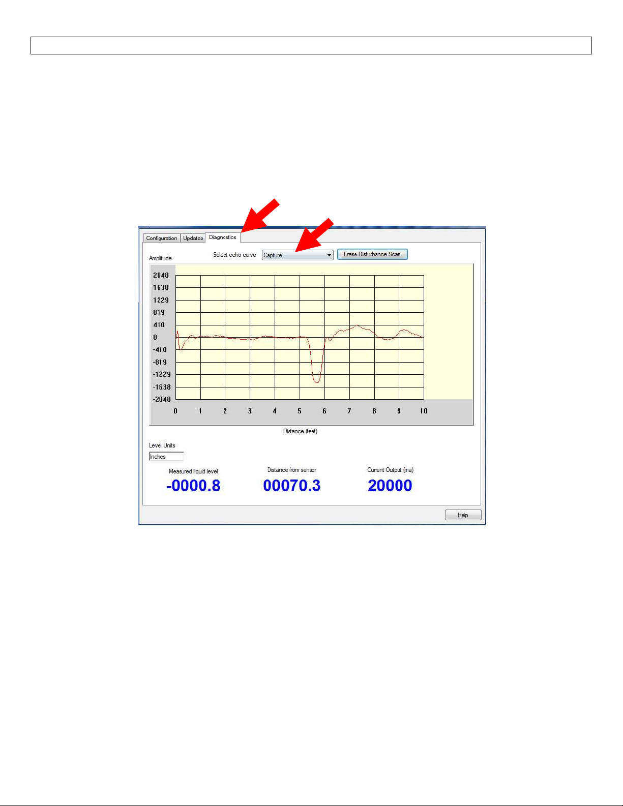
TheEmptySignalScancanbeviewedwiththeLVCN414‐SWsoftware(version6.5andgreater).Note:Always
consultaOmegaEngineering®representativeforreviewingofthesignaldata.Toview,followthe directions
below:
1. Activateanemptysignalscan(seeinstructionsinEmptySignalScan,Section6).
2. ConnectLVRD10SeriestoLVCN414‐SWsoftwareviaFob
3. ClickonDiagnosticsTabonthemainscreen
4. IntheSelectSignalDatapulldown,selectEmptyScan.
5. Theemptysignalscanwillbedisplayedinthewindow.
EraseEmptySignalScanwithLVCN414‐SWSoftware
Ifthereisaneedtoeraseorturnofftheemptysignalscan,performthefollowing:
1. Disconnectthesensorfromtheapplicationwiring.
2. ConnectLVRD10SeriestoLVCN414‐SWsoftwareviaFob.
3. ClickonDiagnosticsTabonthemainscreen.
4. ClickonEraseEmptySignalScan.
30
Page 31
APPENDIX SectionSeven
EchoCurve
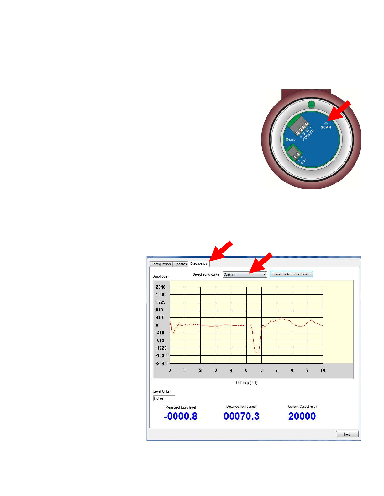
Thisfunctiondisplays theprimary echoreturn(s)thatthe sensoris seeinggraphicallyas well asthelocation
and amplitude of the return(s). It can be used to confirm the correct level reading by the sensor or to
troubleshootanyfalsesignals.Thereisatwostepprocessinvolving the creating and viewing of an echo
curve.Note:AlwaysconsultaOmegaEngineering®representativeforreviewingofthesignaldata.
#1‐CreateanEchoCurve
Tocreateanechocurve,usethefollowinginstructions:
1. Make sure the LVRD10 series is installed within the actual
application.
a. Echo curve will not provide any useful information when
placedoutsideoftheapplication.
2. Press and hold the SCAN button for 1 second (LED will turn off),
thenrelease.
3. Echocurveiscompleted.
a. Toview,youmustconnectthesensortotheLVCN414‐SW
software.
Note: LVRD10series canstore upto atotal ofthree emptysignal scans and/orecho curve. Example:If an
emptysignalscanisactive,LVRD10Serieswillonlystoretwoechocurves.Ifanemptysignalscanisnotactive,
threeechocurvescanbestores.Echocurvesfollowafirstinfirstoutlogic.
#2‐ViewingtheEchoCurve
The echo curve(s)scan can be viewed with theLVCN414‐SW software (version 6.5 and greater). To view,
followthedirectionsbelow:
1. Create an echo curve (see
instructionsabove).
2. ConnectLVRD10Seriestothe
LVCN414‐SWsoftwareviaFob
3. ClickonDiagnosticsTabon
themainscreen
4. In the Select Signal Data pull
down,selectEchoCurve.
5. The echo curve will be
displayedinthewindow.
31
Page 32
APPENDIX SectionSeven
A.SensorConfiguration
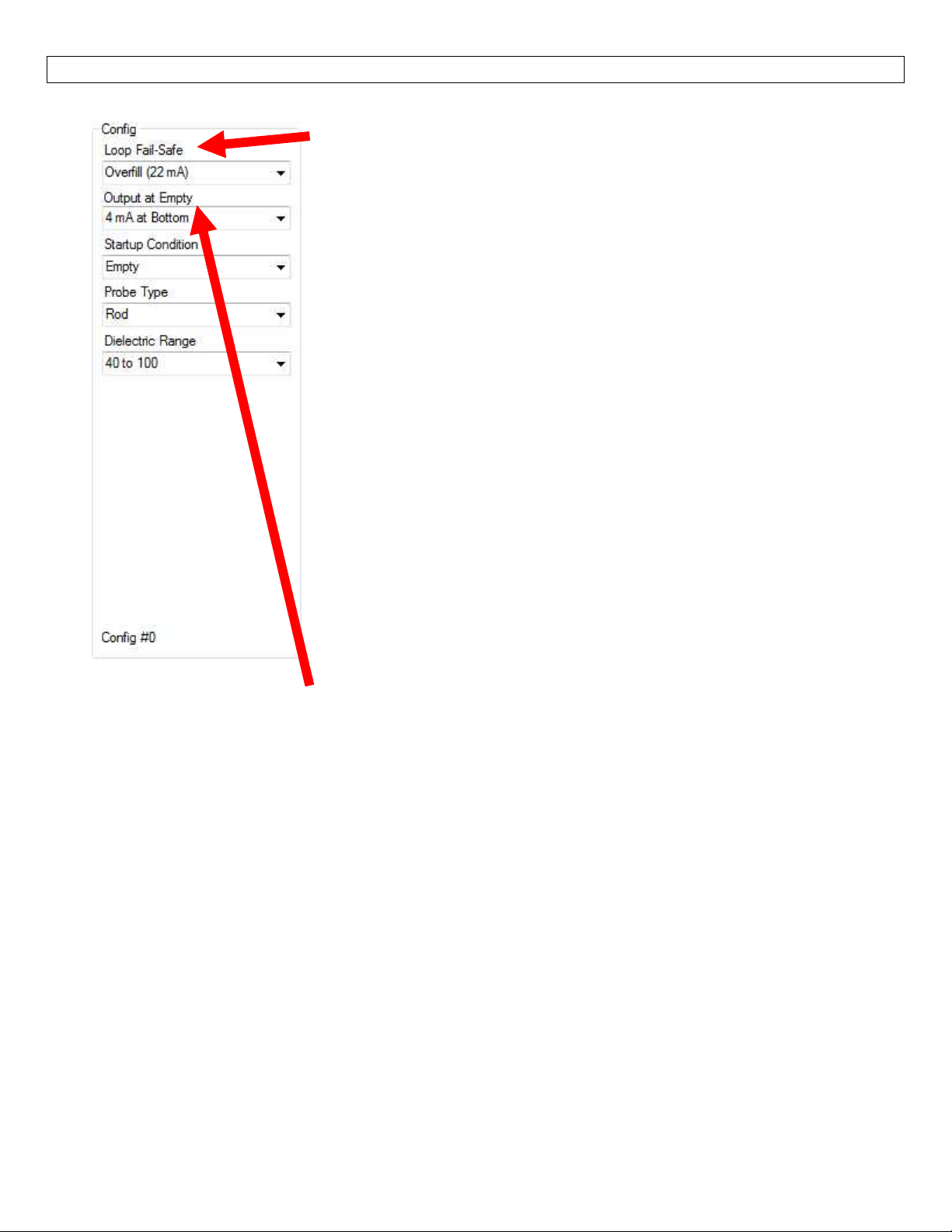
LoopFail‐Safe
Thisfeatureallowsyoutoselectthefail‐safecurrentoutputifthesensor
looses echo confidence (LOST). When the sensor regains echo
confidence, the output current will revert back to the current level
condition.
Hold Last Value‐Theoutput will remain in the samestate as
the lastconfident echo detected. Example: If the output was
6.7mA justprior tothe lost signal, the sensor willcontinue to
output6.7mAuntilechoconfidenceisregained.
Empty ‐ The output will revert to the current value for an
emptycondition.When4mAatBottomisselected,thesensor
will output 4 mA during a fail‐safe condition. If 20 mA at
Bottomis selected,the sensorwilloutput 20mAduring afail‐
safecondition.
Full ‐ The output will revert to the current value for a full
condition. When4 mA at Bottom is selected, the sensor will
output20mAduringafail‐safecondition. If20mAatBottom
is selected, the sensor will output 4 mA during a fail‐safe
condition.
Overfill(21mA)‐Thesensorwilloutput21mAduringafail‐safe
condition.
Overfill(22mA)‐Thesensorwilloutput22mAduringafail‐safe
condition.
OutputatEmpty
Thisfeatureallowsyoutoselecttheorientationofthe4to20mAoutput
(4to20mAor20to4mA).Choosewhichoutputsettingbestfits the
application.Typical applicationsaresetwith 4mAatBottom.Factory
default is 4mA at bottom and 20mA at top. When connecting your
sensortoadisplay,youmustaccountforyouroutputorientationsetting.
4mA at Bottom‐The output current will be 4mA when the
sensormeasuresanemptytankand20mAwhenthesensor
measuresafulltank.
20mA at Bottom‐Theoutput currentwill be20mA whenthe
sensormeasuresanemptytankand4mAwhenthesensor
measuresafulltank.
Note:Rightclickonanyitemtoopenthehelpmenu.
Note:Toresettheconfigurationtable,presstheClearScreenbutton
32
Page 33
APPENDIX SectionSeven
A.SensorConfiguration
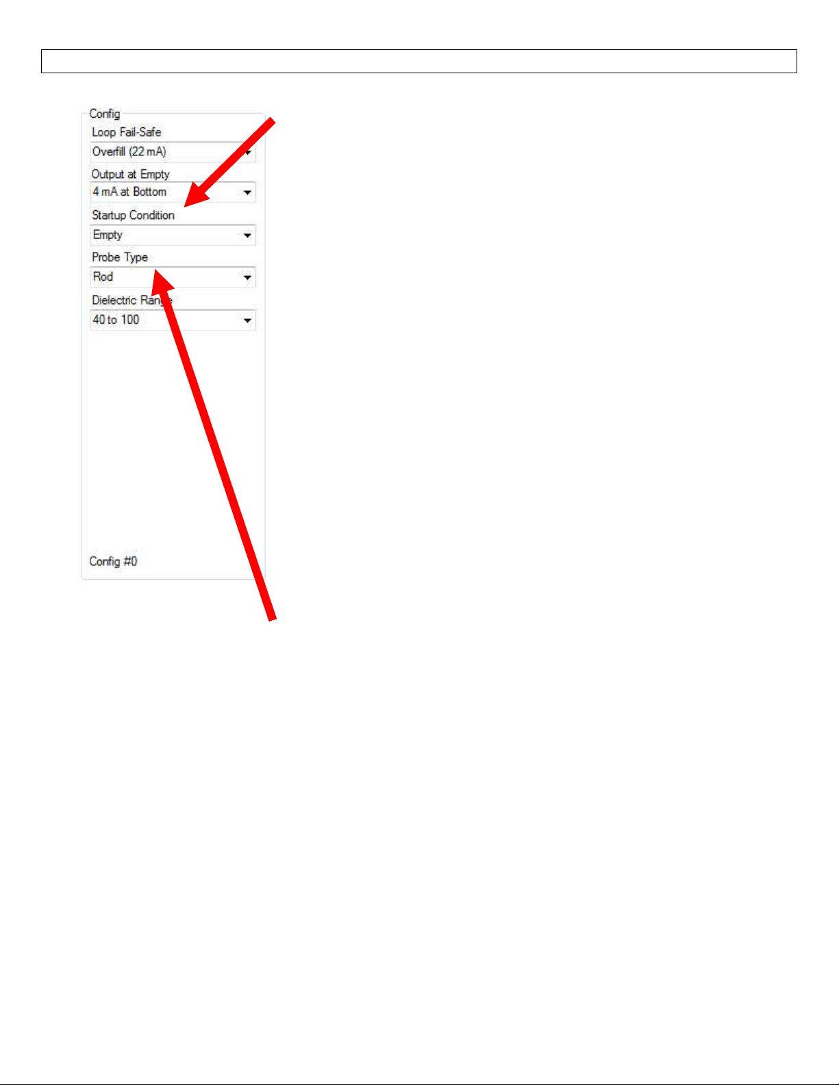
StartupCondition
Thisfeatureallowsyoutoselectthestartupcurrentwhenpowerisfirst
applied to the sensor. The sensor will consume the selected power
whileit isacquiringthe liquidlevel. Whenthecorrect levelhasbeen
identified,theoutput willadjustto the leveloutput. Usethisfeature
toavoidfalsealarmswiththecontrollerwhenpowerisfirstappliedto
thesensor.
Empty ‐The currentoutput willrevert tothe selectedcurrent
valueforanemptycondition.
o 4 mAat Bottom ‐ The sensor will output4 mAwhile the
sensorpowersup.
o 20mAatBottom‐Thesensorwilloutput20mAwhilethe
sensorpowersup.
Mid Tank (12 mA) – The sensor will output 12 mA while the
sensorpowersup.
Full‐Theoutputwillreverttotheselectedcurrentvalueforafull
condition.
o 4 mA at Bottom‐Thesensorwilloutput20mAwhile
poweringup.
o 20 mA at Bottom‐Thesensorwilloutput4mAwhilethe
sensorpowersup.
Overfill(22mA)‐Thesensorwilloutput22mAwhilethesensor
powersup.
ProbeType
Thisfeatureallowsyoutoselectthetypeofprobeattachedtothe
feed‐through.Itiscriticaltoselectthecorrecttypeofprobe.
Rod ‐ Recommended for installations in liquids, in bypass
chambersand stillingwells(when combinedtogether withthe
rodemulateacoaxialprobe).
Cable‐ Recommendedforinstallations intall tanksandwhere
limitedheadroomisavailable.
Coaxial‐Recommended fortheuse withcleanliquids only. It
cannotbeusedwithviscous,crystallizing,adhesive,coating, or
stickyliquids; fibrousliquids, sludge, slurry,pulp orany liquids
containingsolidparticles.
Note:Onlychangetheprobetypewhentheprobehasbeenphysicallychanged.Neverchangethissettingto
improvesensorperformance.ThiswillonlycauseissuewiththeoperationofLVRD10Series.
Note:Rightclickonanyitemtoopenthehelpmenu.
Note:Toresettheconfigurationtable,presstheClearScreenbutton
33
Page 34
APPENDIX SectionSeven
A.SensorConfiguration
DielectricRange
Thisfeatureallowsyoutoselectthedielectricrange,whichsets the
amplitudethresholdwithinthesensor.
Waterbasedmedia(water,H2SO4,HCl)
o 40to100
o 20to39.9
o 10to19.9
Varyingdielectrics(Alcohols,EthylAcetate,CasterOil)
o 9to9.9
o 8to8.9
TypicalHydrocarbons(DieselFuel,MineralOil,Solvents)
Note: It is very important to select the correct range for the dielectric value of the liquid. Choosing an
incorrectrangewillaffecttheperformanceofthesensor.
Note:Rightclickonanyitemtoopenthehelpmenu.
Note:Toresettheconfigurationtable,presstheClearScreenbutton.
B.TankShapeSelection
The sensor may be configured in
volumetric units (Gallons or Liters) or
Distance (Height of Liquid) units (inches,
cm, feet or meters). LVCN414‐SW
softwarewilldefaultinDistance(Heightof
Liquid)withunitsofInches.Tochangethe
units or to change from Distance to
Volume, press the Volumetric Mode
button located near the center of the
window.
o 7to7.9
o 6to6.9
o 2to2.9
o 5to5.9
o 4to4.9
o 3to3.9
Note: The Volumetric Mode button will be
highlightedin Bluewhen avolume outputis
selected.
34
Page 35
APPENDIX SectionSeven
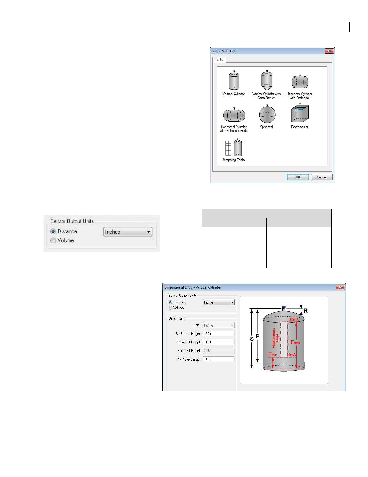
ShapeSelectionWindow:Thiswindowwillshowsthedifferenttankshapeoptionsavailable.
VerticalCylinder
VerticalCylinderwithConeBottom
HorizontalCylinderwithEndcaps
HorizontalCylinderwithSphericalEnds
Spherical
Rectangular
Strapping Table– Usethisfeatureformanualentry
ofmeasuredtankdistancesandvolumes.
Select any of the above tank shapes and press OK to
confirm.
C.DimensionalEntry–VerticalCylinderExample: Choosethe Sensor OutputUnits as Distanceor Volume.
AfterchoosingtheSensorOutputUnits,selecttheunitsofmeasurementinthepulldowntotheleft.
UnitsofMeasurement
Distance Volume
Inches
Cm
Feet
Meters
Gallons
Liters
Distance–SensorOutputUnits(VerticalCylinderExample):
Enterthedimensionsof thetank. Youmust
enterdatainallfieldsshown.
SensorHeight:Distancefromthebottomof
thetanktothetopofthethreads.
Max.Fill Height: Distancefromthe bottom
ofthetanktotheoperationalfulllevelof
liquid (20mA). This setting defines the
locationoffullcurrentoutputand isthe top
ofthesensor’smeasurementrange.
Min.FillHeight:Distancefromthebottomof
the tank to the operational empty level of
liquid(4mA).Thissettingdefinesthelocation
ofemptycurrentoutputandisthebottomofthesensor’smeasurementrange.
ProbeLength:Distanceoftheprobefromthebottomofthethreads(feedthrough)totheendoftheprobe.
35
Page 36
APPENDIX SectionSeven
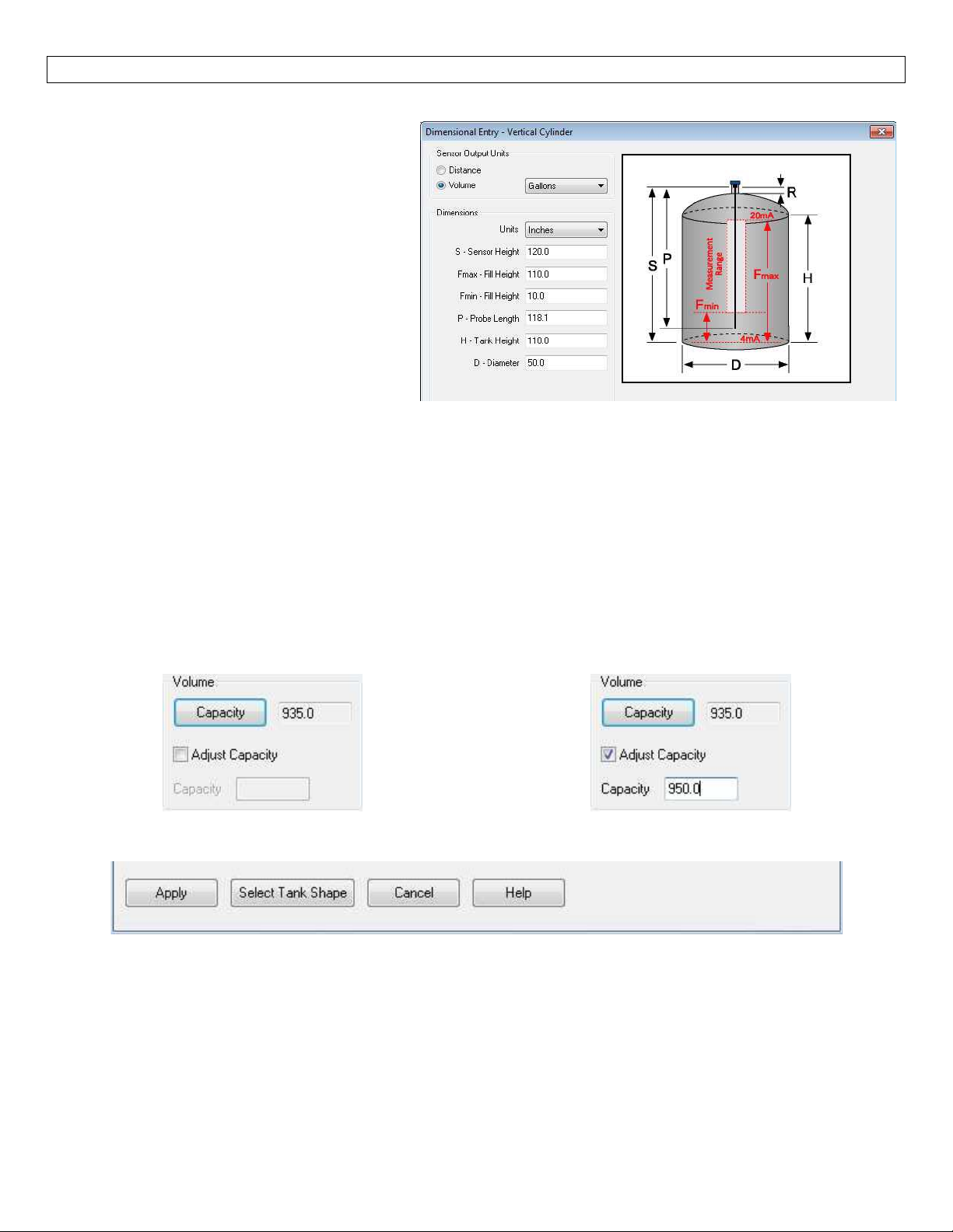
Volume–SensorOutputUnits(VerticalCylinderExample):
Enterthedimensionsof thetank. Youmust
enterdatainallfieldsshown.
SensorHeight:Distancefromthebottomof
thetanktothetopofthethreads.
Max.Fill Height: Distancefromthe bottom
ofthetanktotheoperationalfulllevelof
liquid (20mA). This setting defines the
locationoffullcurrentoutputand isthe top
ofthesensor’smeasurementrange.
Min.FillHeight:Distancefromthebottomof
the tank to the operational empty level of
liquid(4mA).Thissettingdefinesthelocation
ofemptycurrentoutputandisthebottomofthesensor’smeasurementrange.
TankHeight:Distancefromthebottomofthetanktothetopofthestraightsidewall.
Diameter:Distanceoftheinsidetankdiameter.
ProbeLength:Distanceoftheprobefromthebottomofthefeedthroughtotheendoftheprobe.
Volume–TankCapacity(VerticalCylinderExample): After entering the dimensions, press the Capacity
buttonto show the CalculatedCapacity of the tank. If the CalculatedCapacity isslightly differentthan the
expected capacity, click on the Adjust Capacity box and enter the expected capacity of the tank. If the
AdjustedCapacityismorethan10%oftheCalculatedCapacity,recheck the dimensionsinformationentered
above.
Whenalldimensionsareentered,presstheApplybuttontoreturntothepreviousConfigurationwindow.
Apply–TransfersthedimensionstotheoriginalConfigurationwindow.
Tanks–ReturnstothepreviousShapeSelectionwindow.
Cancel–ReturnstotheConfigurationwindowwithoutsavinganyinformation.
Help–JumpstotheHelpmenu.
36
Page 37
APPENDIX SectionSeven
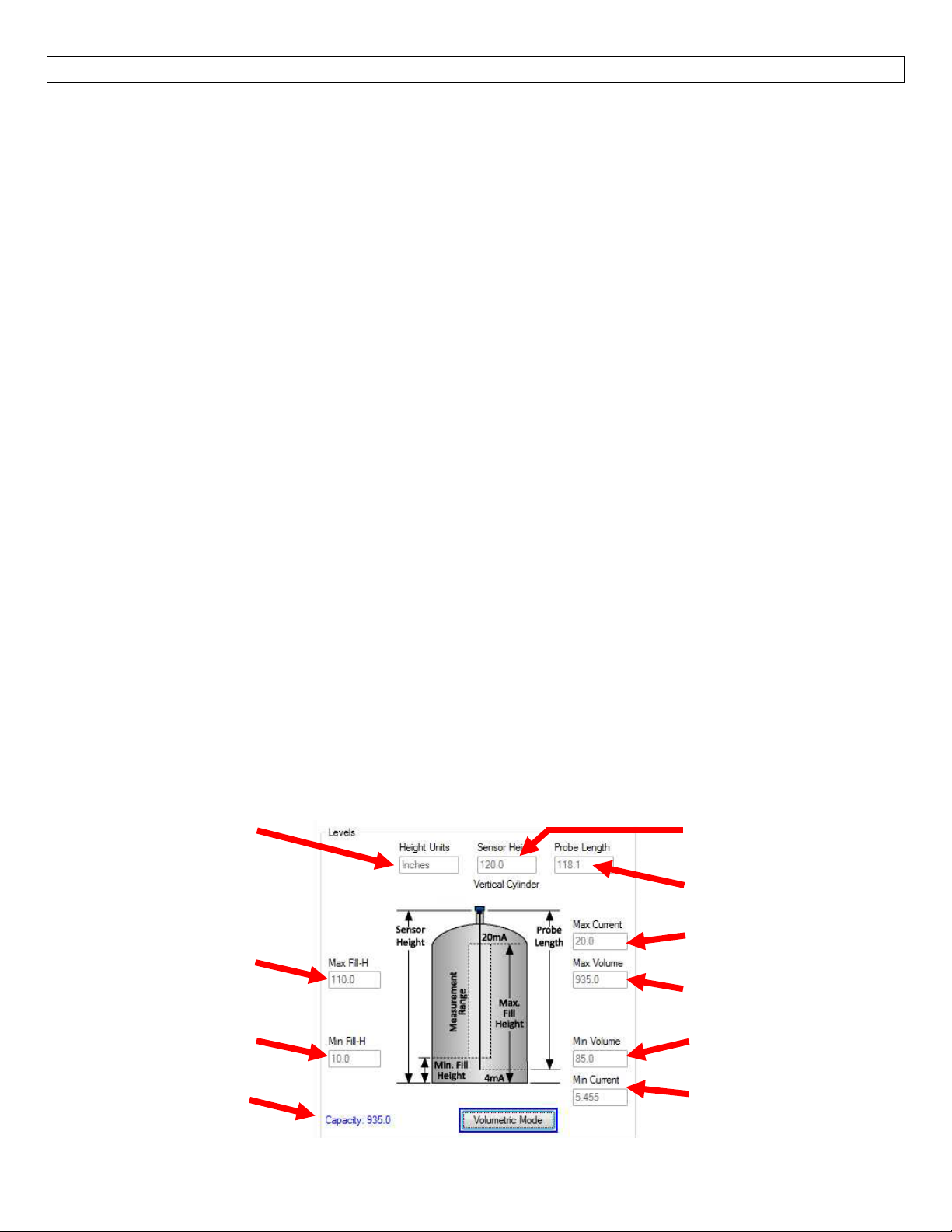
D.TankLevelConfirmation:ThissectionoftheLVCN414‐SWsoftwareiswhereyouconfirmthevaluessetin
thepreviousstep.ThevalueswereenteredundertheDimensionalentrywindow.Toeditthesesettings,you
mustgobacktotheDimensionalentrywindowviatheVolumetricModebutton.
HeightUnits:Unitsselectedforconfiguration.Whenusedasadevicetomeasuretheheightofliquid,
theoptions areinches, cm, feetor m.When usedas adeviceto measurethe volumeofliquid, the
optionsaregallonsorliters.
SensorHeight:Distancefromthebottomofthetanktothebottomofthetopofthethreads.
Max.Fill‐Height:Distancefromthebottomofthetanktotheoperationalfulllevel ofliquid(20mA).
Thissettingdefinesthelocationoffullcurrentoutputandisthetopofthesensor’smeasurement
range.
Min.Fill‐Height:Distancefromthebottomofthetanktotheoperationalemptylevelofliquid(4mA).
This value defines the location of empty current output and is the bottom of the sensor’s
measurementrange.
ProbeLength:Totallengthoftheprobefromthebottomoftheprobetothebottomofthethreads
(feedthrough).
o Cableversiononly:Theheightofthecounter‐weightisincludedinthismeasurement.
Capacity:Thetotalvolumeofthetank.Onlyshownwhengallonsorlitersareselected.
MaximumCurrent: Displayed valueof thelargest operationalcurrent of the sensor’s measurement
range.Typically20mAwhenOutput@Emptyissetto4mA.
MaximumVolume: Displayedvalue ofthe largestoperationalvolume ofthe sensor’smeasurement
range.ThisisthecalculatedvolumeofliquidattheMax.Fill‐Height.Thisfeatureisonlyshownwhen
thesensorisselectedtomeasurethevolumeofliquidinthetank.
MinimumCurrent:Displayedvalueofthesmallestoperationalcurrentofthesensor’smeasurement
range.ThisvalueisdependentonthelocationoftheMin.Fill‐Height.
MinimumVolume:Displayedvalueofthesmallestoperationalvolumeofthesensor’smeasurement
range.ThisisthecalculatedvolumeofliquidattheMin.Fill‐Height.Thisfeatureisonlyshownwhen
thesensorisselectedtomeasurethevolumeofliquidinthetank.
Note:Byextendingtheempty(4mA)tothebottomofthetank,the4‐20mAoutputwilltrackthevolumeofthetank.
Thisallowsanylocaldisplaytoreadtheactualvolumeofliquidwithouttheneedforanyuniqueconfiguration.This
featureisveryusefulwithanynon‐lineartankssuchashorizontal,sphericalor
HeightUnits
Max.Fill‐H
Min.Fill‐H
Capacity
tankswithconebottoms.
SensorHeight
ProbeLength
Max.Volume
Max.Current
Min.Current
Min.Volume
37
Page 38
APPENDIX SectionSeven
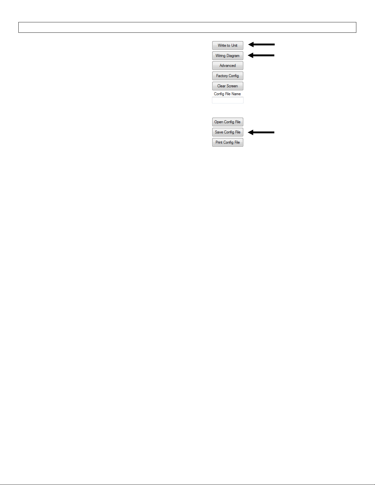
E. Write to Unit ‐ After you have entered
configurations, selected and configured the Tank
Shape and entered the Tank Values, click “Write to
Unit”andloadtheconfigurationintothememoryof
the sensor. Whencompleted, thisconfiguration will
remaininsidethesensormemoryandwillnotchange
unless the sensor is connected to the LVCN414‐SW
softwareandanewconfigurationiswrittentothe
WritetoUnit
Wiringdiagram
sensor. Loss of power will not change or lose the
configurationwithinsensormemory.
SaveConfigFile
Next,usethefilemanagementfeaturestosaveyourconfigurationbyclicking“SaveConfigFile”andprintyour
wiringdiagrambyclicking“WiringDiagram.”
“SaveConfig File”will savethis configuration asa textfile whichcan be loadedback intothe LVCN414‐SW
softwarebypressingthe“OpenConfigFile”button.Itisgoodpracticetosavetheconfigurationfileforeach
different configuration with a unique name for easy identification. If using multiple sensors in identical
applications,thenuseofasingleconfigurationfileisrecommended.
“WiringDiagram”willdisplayaPDFfileshowingtheuniquewiringforthespecificconfigurationcreatedinthe
LVCN414‐SWsoftware.ThePDFcanbeprintedoremailed.Itisgoodpracticetosavethewiringdiagramasa
backup.
38
Page 39
APPENDIX SectionSeven
CuttingtheProbe
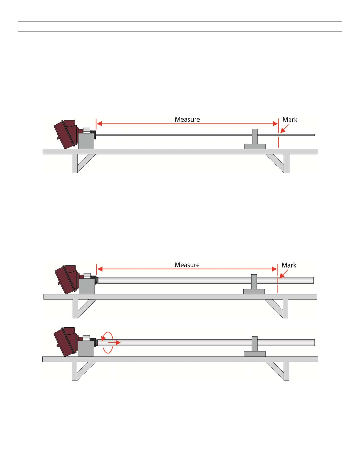
Ifthelengthoftheprobeistoolong(touchesbottomoftank,preventsthesensorfrombeingthreadedinto
thetankorashorterlengthisrequiredfortheapplication),theprobecanbecuttolengthinthefield.Note:
Themostimportantrequirementforcuttingtheprobeistoprotectthehousingfrombeingdropped,banging
intootherobjectsorswingingfreely.Followtheinstructionsfortheappropriateprobestyle.
Rod(LVRD11Series)
Placetheprobeonasturdysurface.
Measureandmarkthelocationforthecut.
Securetherodtopreventitfrommovingduringcutting.
o Besuretosecurethehousingtopreventitfrommovingwhentheprobeiscut.
Useasawwithabladedesignedtocut316LSStocuttheprobe.
o Examplesincludehacksaw,diamondwheelrotarytool,etc.
o Oncetheprobeiscut,trim/filethefreshcut.
Installtheprobepermountinginstructions.
Coaxial(LVRD12Series)
Placetheprobeonasturdysurface.
Measureandmarkthelocationforthecutonthecoaxialshield.
UnthreadthecoaxialshieldfromtheGWRsensor.
39
Page 40
APPENDIX SectionSeven
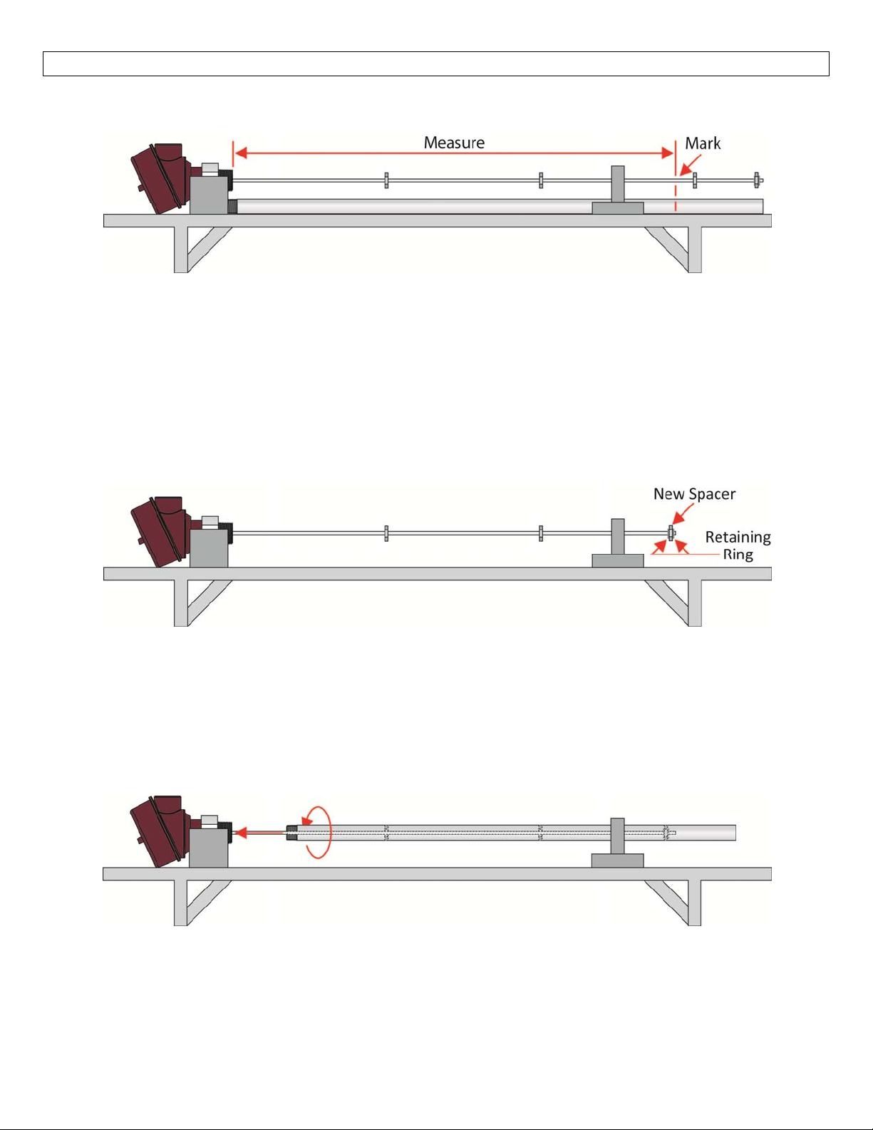
Measureandmarkthelocationforthecutontheexposedrod.
o Usethecoaxialshieldasaguidetoconfirmbothcutsareatthesamelength.
Cuttingtherod
o Securetherodtopreventitfrommovingduringcutting.
Besuretosecurethehousingtopreventitfrommovingwhentheprobeiscut.
o Useasawwithabladedesignedtocut316LSStocuttheprobe.
Examplesincludehacksaw,diamondwheelrotarytool,etc.
Oncetheprobeiscut,trim/filethefreshcut.
o Attachaspacertotheendofprobe.
Offsetthespacerapprox.1/8”(3mm)fromtheendoftheprobe.
Makesuretheremainingspacersarenofurtherthan39.4”(1m)apart.
Secureretainingringsoneachsideofthespacer.
Cuttingthecoaxialshield
o Securethecoaxialshieldtopreventitfrommovingduringcutting.
o Useapipecutterwithabladedesignedtocut316LSStocutthecoaxialshield.
Ahacksawcanbeusedtocutthecoaxialshieldifthepipecutteristoodifficult.
Usetheinitialcutofthepipecutterasascorelineforthehacksaw.
Oncethecoaxialshieldiscut,trim/filethefreshcut.
Slidethecoaxialshieldovertherodmakingsurenottomovethespacers.
ThreadthecoaxialshieldtotheGWRsensor.
Installtheprobepermountinginstructions.
40
Page 41
APPENDIX SectionSeven
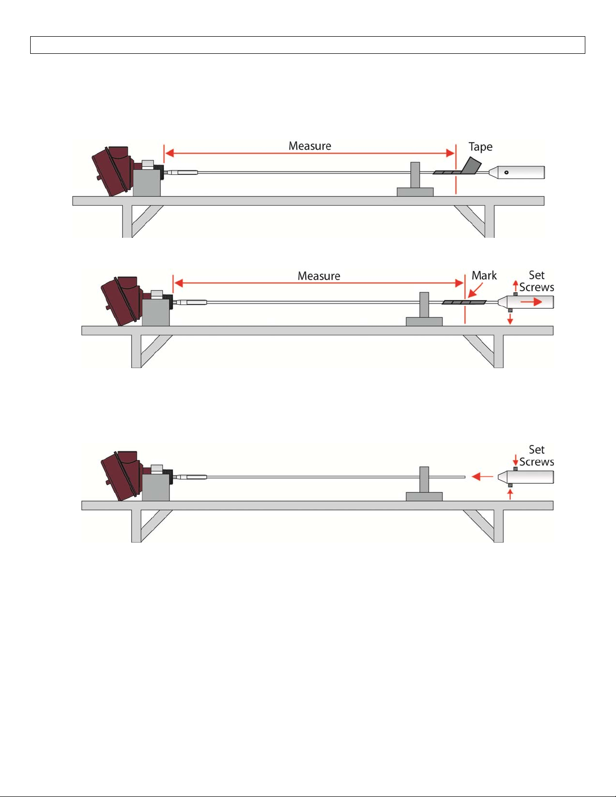
Cable(LVRD13Series)
Placetheprobeonasturdysurface.
Measurethelocationforthecutonthecable.
Wrapthecablewithelectricaltapealongtheareaofthecut.
o Thiswillpreventthecablefromfrayingwhilebeingcut.
Markthelocationofthecutontheelectricaltape.
Loosenthe(¼–20,⅛Hex)setscrewsinthecounterweightandremovefromthecable.
Securethecabletopreventitfrommovingduringcutting.
o Besuretosecurethehousingtopreventitfrommovingwhentheprobeiscut.
Usingawirecutterorarotarytool,cutthecable.
o Oncetheprobeiscut,removethetapekeepingthecableintact.
Insertthefreshlycutcableintothecounterweightandtightenthe(¼–20,⅛Hex)setscrews.
Installtheprobepermountinginstructions.
41
Page 42
APPENDIX SectionSeven
FactorySettings:
FromBottom
(Lowestpointofprobe)
ProbeStyle Sensor 4mA 20mA 4mA 20mA
Rod
(LVRD11Series)
Coaxial
(LVRD12Series)
Cable*
(LVRD13Series)
LVRD11
Series
LVRD11‐3FT
Series
LVRD11‐6FT
Series
LVRD12
Series
LVRD12‐3FT
Series
LVRD12‐6FT
Series
LVRD13Series
2.0”
(50.8mm)
2.0”
(50.8mm)
2.0”
(50.8mm)
2.0”
(50.8mm)
2.0”
(50.8mm)
2.0”
(50.8mm)
7.9”
(200.7mm)
114.8”
(2915mm)
32”
(812.8mm)
68”
(1727.2mm)
114.8”
(2915mm)
32”
(812.8mm)
68”
(1727.2mm)
219.1”
(5566mm)
(BottomofMountingNut)
(2966mm)
(862.6mm)
(1778.0mm)
(2966mm)
(862.6mm)
(1778.0mm)
(5145mm)
116.8”
34”
70”
116.8”
34”
70”
216.2”
FromTop
3.4”
(85.1mm)
3.4”
(85.1mm)
3.4”
(85.1mm)
3.4”
(85.1mm)
3.4”
(85.1mm)
3.4”
(85.1mm)
3.4”
(85.1mm)
Cable‐includescounter‐weight
Note:CableversionsoftheLVRD13seriesmustaccountforthecounterweightattachedtotheendofthe
probe.
Note:WhenclickingontheFactoryConfig.Buttonintheconfigurationsoftware,thiswillreturnthesensorto
itsbasedfactoryconfigurationwhichisforthefulllengthsensor(i.e.LVRD11,LVRD12orLVRD13)andnotany
oftheshorterlengthconfigurations(i.e.LVRD‐11‐3FT,LVRD‐12‐6FT,etc.).
Troubleshooting:
PROBLEM SOLUTION
NoLED
LEDflashesRed
Sensorislockedonalevel
abovethetruelevel.
Sensor is not receiving power (10 to 30 VDC). Check wiring to the
sensoraswellasthepowersupply.
Sensorcannotacquireavalidlevelreading.Makesurethesensor is
installed properly within the application and the probe is touching
liquid.
Sensorislikelyacquiringafalseechofromsomeinterferenceclose to
theprobe.RunninganEmptySignalScanshouldaddressthisissue.
42
Page 43

43
Page 44

44
 Loading...