

Page 1
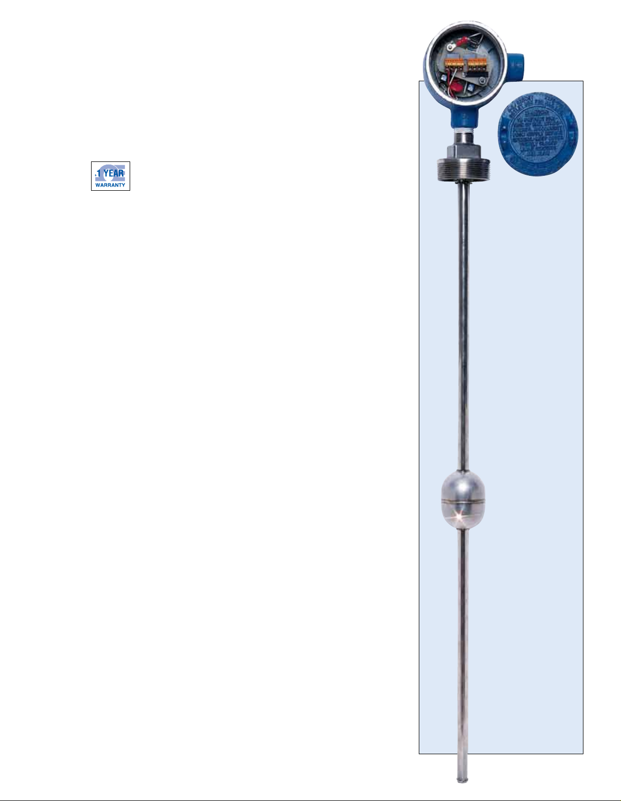
ECONOMICAL LIQUID-LEVEL
TRANSMITTERS
SUITAbLE fOR LEVELS TO 6 fEET
LVR20/30 Series
U Rugged Stainless Steel
Construction
U 4 to 20 mA or Resistance
Output
U Immune to Density and
Dielectric Changes
U 1⁄4” Resolution
The OMEGA® LVR20 and LVR30
Series continuous liquid-level
sensors operate on a basic voltage
divider network principle. As the
float rises, a magnet in the float
closes a series of reed switches in
sequence, which varies the tapped-off
portion of the voltage divider resistor
network. The LVR20 has the basic
voltage divider output—the regulated
DC voltage input equals the maximum
voltage output. The LVR20 has a
nominal 1200 resistance; thus, with
a 10 Vdc supply, 8.3 mA of current
is required.
The OMEGA® DPF52 or DP24-E
panel meters can be used to power
and display the resistance from the
LVR20; when relays are required,
the DP25E-A meter can be used.
For maximum accuracy, the readout
device for the LVR20 should be
zero and span adjusted after wiring
is completed to compensate for any
effects caused by the resistance
of the lead-wires. The LVR20 can
also be made intrinsically safe when
used with OMEGA’s intrinsic safety
barriers and when properly powered.
The LVR30 Series features a signal
conditioner that provides a
4 to 20 mA output when powered by
10 to 30 Vdc. The LVR30 transmitters
cannot be made intrinsically safe.
All LVR30 units come with a J-box
with screw terminal connections.
LVR20 units do not come with a
J-box but have 24 inches of bare
wire coming out of the top of the unit
with a 1⁄2 MNPT conduit connection.
All LVR20 and LVR30 Series units
can be wired for increasing output
with either increasing or decreasing
height of liquid; standard output is
increasing output with increasing
height. For other lengths, adaptor
systems are available. These
consist of 2 parts: the LVR-C
coupling (2 x 2 FNPT) and an
LVR-A pipe nipple (2 x 2 MNPT)
of various lengths to change the
insertion depth of the LVR20 or
LVR30 sensor. When using the
adaptors, a zero offset is introduced
into the output signal, which must
be compensated for in the readout
device (for example, the mA signal,
will not go down to 4 mA, nor will
the voltage output go down to zero).
Retaining clip pliers are required
to remove the float when using the
adaptor system.
SPECIFICATIONS
Wetted Parts: 316 SS stem and
mounting, 316 SS float, 18-8 SS
float stop
Liquid Temperature:
To 82.2°C (180°F) in water
Minimum Liquid Specific Gravity: 0.75
Operating Temperature:
-40 to 110°C (-40 to 230°F)
LVR30 Temperature Coefficient:
±0.00388% FS/°F
Max Operating Pressure: 300 psig
Operating Voltage:
LVR30: 10 to 40 Vdc
LVR20: 10 to 30 Vdc
LVR30 Loop Impedance: (Volts in - 10)
x 46.66 = Ω with 24 Vdc power,
maximum loop impedance = 653 Ω
Connections: LVR30 is 2-wire;
LVR20 is 3-wire
Accuracy:
LVR30: 0.4% of FS or ±
is greater
LVR20: ±
Weights:
LVR30: 5 lb +
LVR20: 1
LVR-C:1
1
⁄2"
1
⁄4 lb per foot
3
⁄4 lb + 1⁄4 lb per foot
1
⁄4 lb
1
⁄2", whichever
LVR20 Supplied
Without J-box
LVR31 shown
smaller than
actual size.
Indicating
Lengths from
1 to 6 Feet
LVR30 Series
Shown Smaller
Than Actual Size
K-15
Page 2
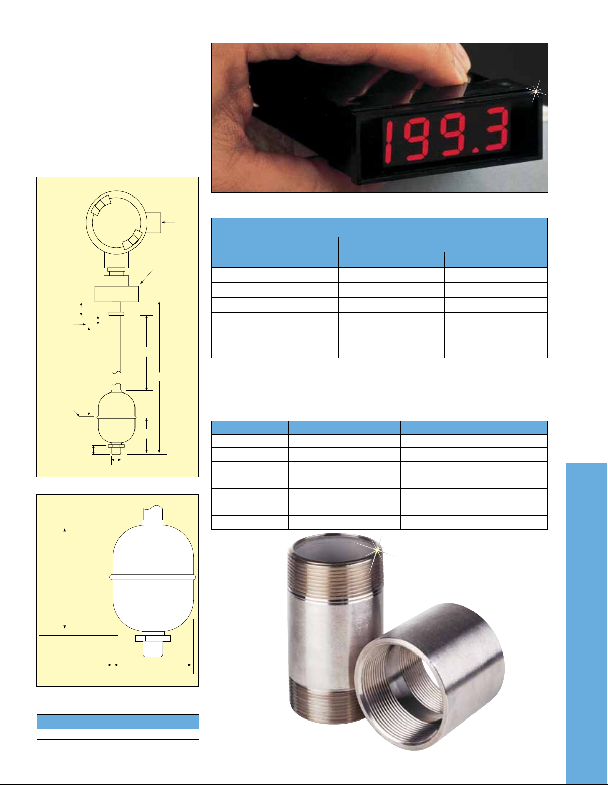
Dimensions for LVR20 and LVR30
2 MNPT
C
Indicating
Length
Lowest
Level
Indicated
D
A
B
E
8 (5/16)
13 (1/2)
1/2 FNPT
J-Box
Supplied
with LVR30
only
Highest
Level
Indicated
A: Float travel =
indicating length 3⁄8" ±1⁄4"
B: Stem length =
indicating length 39⁄16" ±1⁄16"
C: Distance to float stop =
6.4 mm (1⁄4") ±1⁄16”
D: 39.7 mm (19⁄16")
E: 44.5 mm (13⁄4")
(assumes 1.0 SG fluid)
Assembly Dimensions
Dimensions:
mm (inch)
Use the LVR20 and LVR30 transmitters with the DPF50 Series indicators.
To Order
Isolated 4 to 20 mA Output Voltage Divider Voltage in = Voltage out
Model No. Model No. Indicating Length
LVR31 LVR21
LVR32 LVR22
LVR33 LVR23
LVR34 LVR24
LVR35 LVR25
LVR36 LVR26
Ordering Examples: LVR31, 316 SS level sensor with mounted J-Box and 0.3 m (1')
indicating length.
LVR22, 316 SS level sensor with 0.6 m (2') long indicating length, nominal 0 to 1200 Ω
resistance change and a 2 MNPT mounting thread.
1 ft
2 ft
3 ft
4 ft
5 ft
6 ft
Float
Dimensions: mm (inch)
69.9
(2-3/4)
52.4 (2-1/16)
DIA. TYP
Pipe Nipples, 304 SS, 150 lb fittings, 2 x 2 MNPT
Model No. Weight (lb) Indicating Length Change
LVR-A4
LVR-A5
LVR-A6
LVR-A7
LVR-A9
LVR-A11
LVR-A13
LVR-A4 shown
smaller than
actual size.
11⁄4 4"
1
⁄2 5"
1
13⁄4 6"
2 7"
1
⁄2 9"
2
3 11"
1
⁄2 13"
3
K
150 lb, 304 SS Coupling, 2 x 2 FNPT
Model No.
LVR-C
LVR-C shown
smaller than
actual size.
K-16K-16
 Loading...