

Page 1
2
1
Page 2

Page 3

INTRODUCTION/TABLEOFCONTENTS StepOne
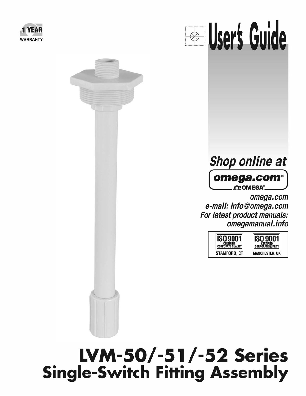
About Omega Engineering’s Single‐Switch Fitting Assembly:Omega Engineering’s Single‐Switch Fitting
Assemblyisanindustrialmountingsystemforinstalling a liquid level sensor vertically within a tank.Omega
Engineering’s LVCN‐11 or LVCN‐12 electrical housing, and LVCN‐100, LVCN‐110 or LVCN‐20 compact relay
controllers are designedto be mounteddirectly to the3/4" NPT fitting atthe top of the assembly.Single‐
SwitchFittingAssemblymountsverticallythroughastandard2"NPTtankadapteroronasidemountbracket
(suchastheVM‐30).
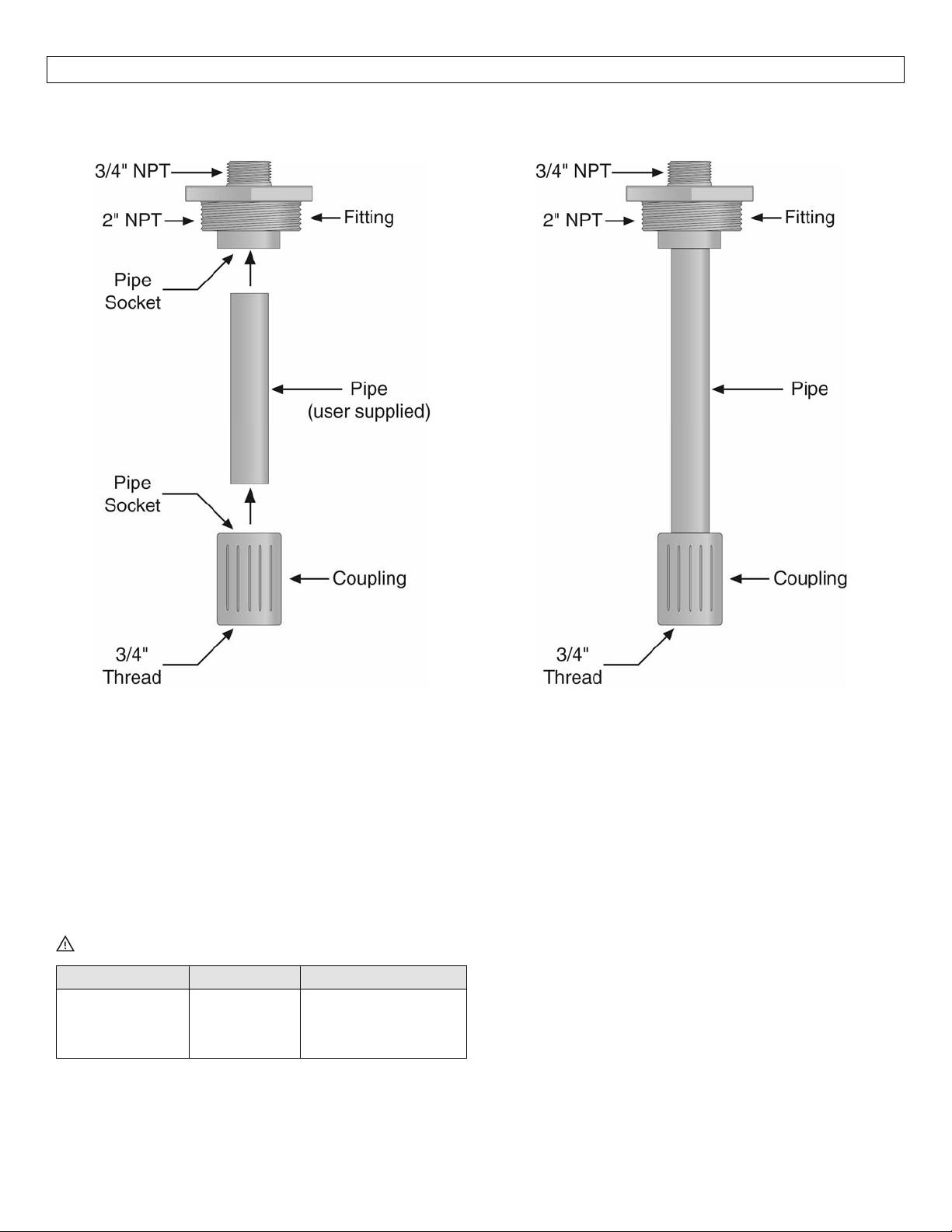
Single‐SwitchFittingAssembly:TheSingle‐SwitchFittingAssemblyconsistsofthefollowing:
Pipe:TheSingle‐SwitchFitting Assembly featuresastandard¾”pipeas the extensionforthesensor.
When assembling a Single‐Switch Fitting Assembly, use a thermal weld for the LVM‐51 series (PP
version) and LVM‐52 series (PVDF version) and a solvent weld for the LVM‐50 series (PVC version).
WeldsmustbemadefortheFitting[2”]andfortheCoupling(3/4”).
Fitting[2”]:Thepipeslidesintotheslipconnectionofalargefittingwhichhasa¾”threadsonthetop
and a 2” standard threads on the bottom.Theslipconnection is located on thesame sideas the 2”
threads.The¾”threadisavailableforattachingajunctionboxorconduit.
Coupling (3/4”):The coupling has a slip end and a ¾” threaded end.The other end of the pipe
attachestotheslipendofthecoupling.The3/4"threadontheotherendattachesthelevelsensorto
theSingle‐SwitchFittingAssembly.
TableofContents
Specifications:.........................................................................................................................................................4
Dimensions:.............................................................................................................................................................4
SafetyPrecautions:.................................................................................................................................................5
MakeaFail‐SafeSystem:............................................................................................................................5
AssemblyofaSingle‐SwitchAssembly:.................................................................................................................6
Components:..............................................................................................................................................6
Installation..............................................................................................................................................................7
MountingtoaSensor:...............................................................................................................................8
SelectingaLocation:.................................................................................................................................8
3
Page 4
SPECIFICATIONS/DIMENSIONS StepTwo
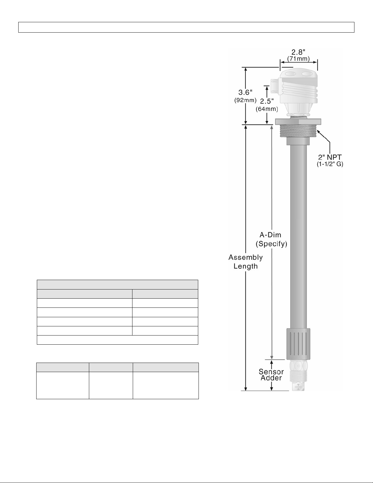
Single‐SwitchFittingAssemblyFitting:
Fittinglengths: 6”to6’(150mmto1.82m)
Fittingtolerance: 1/8”(3mm)typical
Temperaturerange.: F:‐40to176°
C:‐40to80°
Pressurerange: 150psi(10bar)@25°C.,derated@
1.667psi(0.113bar)per°Cabove25°C.
Trackmaterial: Polypropylene(PP),
PolyvinylideneFluoride(PVDF)or
Polyvinylchloride(PVC)
Mountingthread: 2”NPT
JunctionBox:
Enclosurerating: NEMA4X(IP65)
Enclosurematerial: Polypropylene(U.L.94VO)
Enclosurerotation: 300°swivelbase
Conduitconnection: ½”NPT
Termination: 6polesocketterminalstrip
Temperaturerange.: F:‐40to158°
C:‐40to70°
SideMountBracket:
BracketMaterial: Polypropylene
Mountingthread: 2”NPT
Tankinstallation: Boltorplasticweld
SwitchAddersforOmegaEngineeringLevelSensors:
NominalSensorAdders
Technology Lengthadder
LVU‐150series *2.0”(51mm)
LVC‐152series 4.0”(102mm)
LVF‐212Series *2.0”(51mm)
LVV‐110Series 4.3”(109mm)
*Basedupontheshortswitchlength
UserSuppliedPipeSizes:
PartNumber Material PipeSize
LVM‐50‐*
LVM‐51‐*
LVM‐52‐*
PVC
PP
PVDF
¾”(schedule40)
25mm(metric)
25mm(metric)
Single‐SwitchFittingAssemblySideView
4
Page 5

SAFETYPRECAUTIONS StepThree
AboutThis Manual:PLEASEREAD THEENTIREMANUALPRIORTO INSTALLINGORUSINGTHISPRODUCT.
This manual includes information on the Single‐Switch Fitting Assembly installation fitting from Omega
Engineering: LVM‐50/‐51/‐52 series.Please refer to the part number locatedon thelabel toverify the
exactmodelwhichyouhavepurchased.Manyaspectsofinstallationandusearesimilarbetweenmodels.
User’s Responsibility for Safety:OMEGA ENGINEERING manufactures several models of liquid level
sensors, controller and mounting systems.It is the user’s responsibility to select components that are
appropriatefor the application, install it properly,perform tests of theinstalled system, and maintainall
components.Thefailuretodosocouldresultinpropertydamageorseriousinjury.
Proper Installation and Handling:Use a proper sealant with all installations.Never over tighten the
components.Alwayscheckforleakspriortosystemstart‐up.
MaterialCompatibility:Thepipe,fittingandcouplingforalltheLVM‐50/‐51/‐52seriesaremadeofoneof
threematerials,Polypropylene(PP),PolyvinylideneFluoride (PVDF)orPolyvinylchloride(PVC).Makesure
that the application liquids are compatible with the materials that will be wetted.To determine the
chemical compatibility between the components and its application liquids, refer to the Compass
CorrosionGuide.
TemperatureandPressure:Single‐SwitchFittingAssemblyisdesignedforuseinapplicationtemperatures
upto80°C(176°F).Itisdesignedforuseinapplicationpressuresupto150psi(10bar).
Wiring and Electrical:Electrical wiring of any liquid level control system should be performed in
accordance with all applicable national, state, andlocal codes.Take carenot to cut or break the outer
insulation jacket of wiring that may be immersed while routing cables in the Smart Trak system.Such
breaksoftheliquidsealofthesensorsystemmayleadtocomponentfailure.
Flammable or Explosive Applications: Single‐Switch Fitting Assembly may be used within flammable or
explosiveapplicationsonlyiftheassociatedcomponentsareratedintrinsicallysafeforsuchuse.Referto
the National electric Code (NEC) for all applicable installation requirements in hazardous locations.In
hazardous applications, useredundant measurement and
technology.
MakeaFail‐SafeSystem:Designafail‐safesystemthataccommodatesthepossibilityofsensororpower
failure.Incriticalapplications,OmegaEngineeringrecommendstheuseofredundantbackupsystemsand
alarmsinadditiontotheprimarysystem.
control points, each having a different sensing
5
Page 6
ASSEMBLYOFSINGLE‐SWITCHFITTINGASSEMBLY StepFour
Single‐SwitchFittingUnassembledDrawing
(sideview)
Single‐SwitchFittingAssemblyDrawing
(sideview)
Components:One Single‐Switch Fitting Assembly
(LVM‐50‐*, LVM‐51‐*, LVM‐52‐* series) includes
thefollowingparts:
1Fitting(oneofthefollowing)
o LVM‐50‐*
o LVM‐51‐*
o LVM
o *=Fittingsonly,nopipesupplied
1Coupling
Owner’sManual
Pipeisusersupplied.
PartNumber Material PipeSize
LVM‐50‐*
LVM‐51‐*
LVM‐52‐*
‐52‐*
PVC
PP
PVDF
¾”(schedule40)
25mm(metric)
25mm(metric)
Components:One Single‐Switch Fitting Assembly
(LVM‐51‐1.0, LVM‐51‐1.5, LVM‐51‐2.0, LVM‐51‐2.5,
LVM‐51‐3.0, LVM‐51‐3.5, LVM‐51‐4.0, LVM‐51‐4.5,
LVM‐51‐5.0, LVM‐51‐5.5 & LVM‐51‐6.0 series)
includesthefollowingparts:
1Fitting(oneofthefollowing)
o LVM‐51‐1.0’
o LVM‐51‐1.5’
o LVM‐51‐2.0’
o LVM‐51‐2.5’
o LVM‐51‐3.0’
o LVM‐51‐3.5’
o LVM‐51‐4.0’
o LVM‐51‐4.5’
o LVM‐51‐5.0’
o LVM‐51‐5.5’
o LVM‐51‐6.0’
1Coupling
1CustomerSpecifiedPipe
Owner’sManual
6
Page 7
INSTALLATION StepSix
Single‐SwitchFittingAssemblycanbeshippedinoneoftwomethods,AssembledandUnassembled.Withthe
assembled version, the LVM‐50/‐51/‐52 series has been shipped a one complete fitting and the first step
belowcan beshipped.Withtheunassembledversion,Single‐SwitchFitting Assemblyisshippedwithjust the
fittingandcouplingandtheusersuppliedpipewillneedtobeadded.WhenassemblingaSingle‐SwitchFitting
Assembly, use a solvent weld for the LVM‐50‐* (PVC version) and a thermal weld for the LVM‐51‐* (PP
version)andLVM‐52‐*(PVDFversion).
1. AssemblinganunassembledSingle‐SwitchFittingAssembly:
a. Make surethepipebeing used isthesame materialofconstructionas the fittingandcoupling
received.
i. LVM‐50‐*ismadeof¾”(schedule40)Polyvinylchloride(PVC)
ii. LVM‐51‐*ismadeof25mm(metric)Polypropylene(PP)
LVM‐52‐*ismadeof25mm(metric)PolyvinylideneFluoride(PVDF)
iii.
b. Cutthepipetothecorrectlengthtakingintoaccountthetotalheightofthefittingandcoupling
andthedepththepipewillextendintothepipesockets.
c. Prepare the pipeas well asthe pipe
sure they are clean for either the thermal weld (PP or PVDF versions) or solvent weld (PVC
version).
d. Weld the pipe to the fitting and to the coupling using a thermal weld for the PP and PVDF
fittingsandasolventweldforthePVCfittings.
Allowtimefortheweldstocurebeforecontinuingontothenextstep.
2. Attachsensortothecoupling:
a. Threadthesensor’swirethroughthethreadedpartofthecouplingandallthewaythroughthe
LVM‐50/‐51/‐52seriesuntilitextendsouttheotherend.
i. Makesuretheendofthewireissufficientforconnectionsontheotherend.Ifnot,you
may be required to extend the wire within the LVM‐50/‐51/‐52 series to achieve the
correctwirelength.
b. Apply asealant,suchasTeflontapetothethreadsofthesensor.
c. Threadthesensorintothecouplingmakingsureitishandtight.
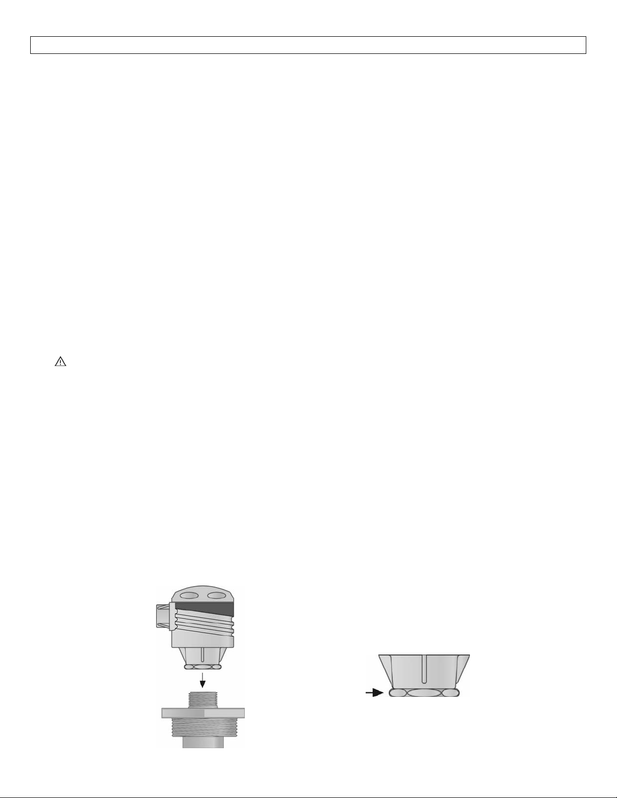
3. Attach the termination hardware:At this point, a junction box housing (LVCN‐11/‐12 series) or
Compact Relay Controller (LVCN‐20/‐100/‐110series) maybescrewed onto the topofthe assembly,
and wiring attachments madefollowing theinstructions in its manual.Assumingthat eachsensor is
alreadymountedinposition,cutthesensorwirestothelengthapproximately1‐1/2”abovethetopof
the housing.However, be sure to make allowances when cutting the sensor leads for future
adjustmentstothesensor
position.
sockets on thefitting and couplingfor assembly making
Note:Alwaystighten thecontrollerfrom
the wrench flat located on the swivel
base.Nevertighten from the body of the
controller.
7
Page 8
INSTALLATION(continued) StepSix
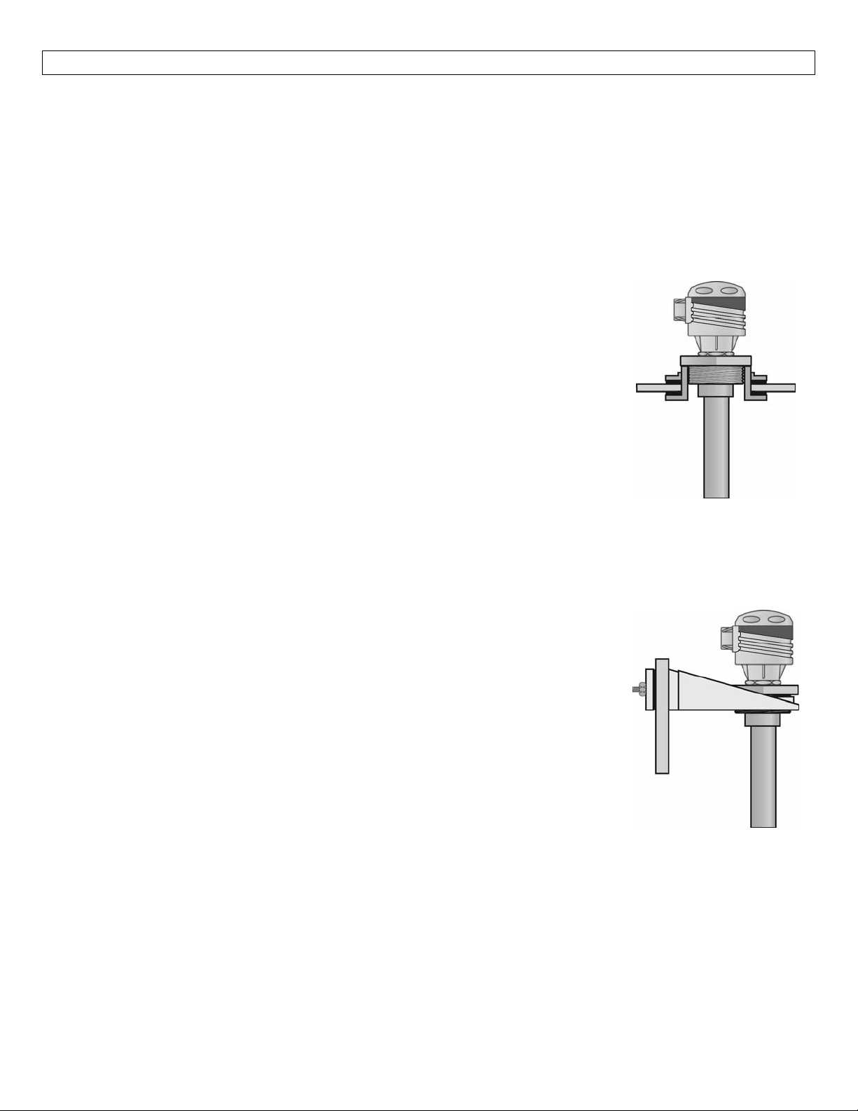
SelectingaLocation:TheSingle‐SwitchFittingAssemblysystemshouldbemountedverticallyatapointinthe
tankwhereitwillnotbeexposedtoexcessivestress.Whenmountinginatankwithamixer,mounttheLVM‐
50/‐51/‐52 series closeto the tank wall were velocities arelowest.Choose a mountinglocation where the
sensors will functioncorrectly (away frominlet pipes thatmay spray onthe sensors causingfalse readings)
andwherethesensortechnologiesfunctionbest.
It is the user’s responsibility to identify the proper placement and method of installation for the specific
application.
TankTopMounting:
1. Installastandard 2”NPTtankadapterthrough thetopof thetankatthe
desiredlocation.Ifthetanktopisnotflat,usea2”NPTself‐aligningtank
adapter.Makesurethethreadsoftheadapterarenotdamagedorworn.
Ifdamaged,useanewadapter.
2. Insert the assembled Single‐Switch Fitting Assembly system throughthe
tankadapter.If several sensorsaretoo close togethertofit through the
tankadapter,slidethemtoadifferentlocationssothatonlyonesensoris
goingthroughtheadapteratatime.
3. To ensure a proper seal,apply an appropriatesealant to thethreads of
the Single‐Switch Fitting Assembly system.Screw the LVM‐50/‐51/‐52
seriesassemblyintothetankadapter.
4. Makeadjustmentsasrequiredtothesensorposition.
5. Connect the external wiring and conduit to the terminal strip or
controller,followingtheinstructionsinthatmanual.
SideMountBracketMounting:
1. Install the side mount bracket (LVM‐30 series) at the desired location.
Make sure the threads of the bracket are not damaged or worn.If
damaged,useanewbracket.
2. Insert the assembled Single‐Switch Fitting Assembly system into the
bracket
3. ScrewtheLVM‐50/‐51/‐52seriesassemblyintothebracket.
4. Makeadjustmentsas required tothesensor position, andtothebracket
tiltingarm.
5. Connect the external wiring and conduit to the terminal strip or
controller,followingtheinstructionsinthatmanual.
8
Page 9

9
Page 10

10
Page 11

11
Page 12

12
 Loading...