

Page 1
Page 2
ASSEMBLYOFSWITCHCAR StepOne
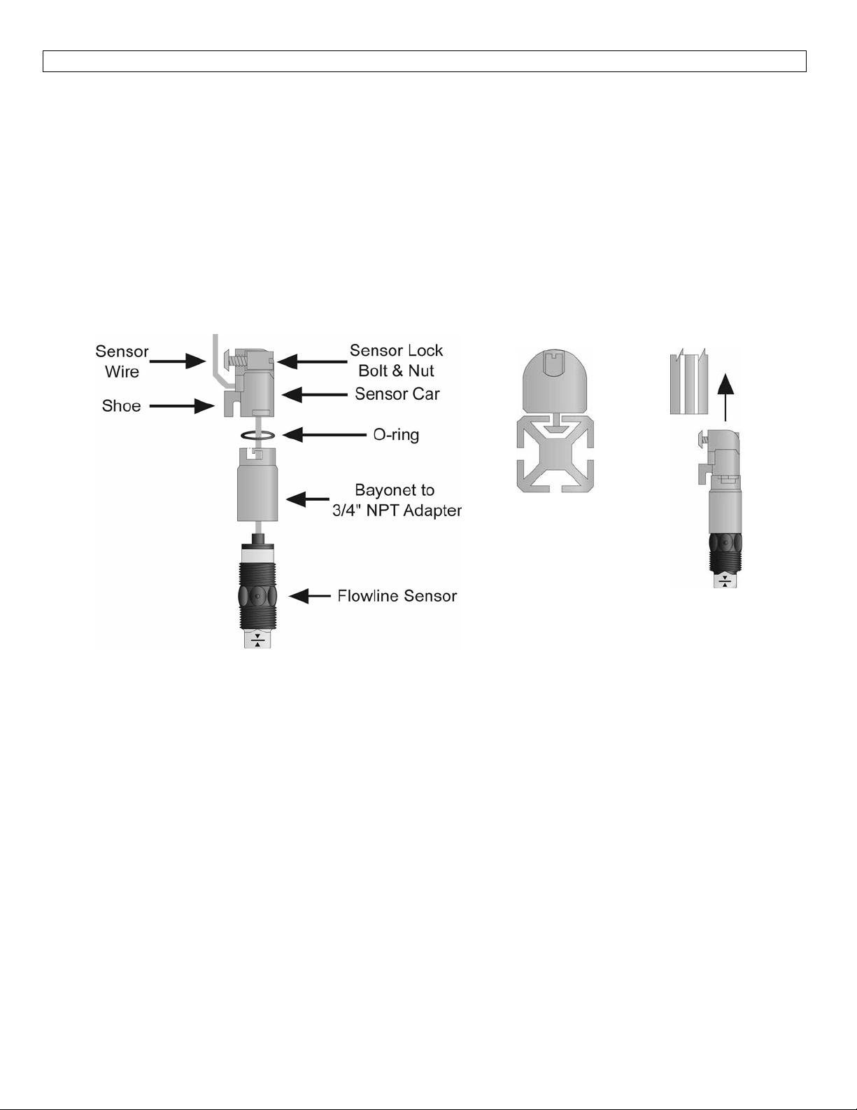
Sensor car and bayonet adapter:The sensor car, LVM‐20 series, is the heart of the Level Trak mounting
system(LVM‐10series).Itslidesinthegroovesofthetrack,andislocked into position by a plastic bolt and
screw.The bayonet to 3/4" NPT adapter has a female 3/4" NPT fitting on one end where the sensor (not
included)willscrewin,andabayonetfittingontheotherendthatattachesitontothesensorcarwithaslight
turn,withanO‐ringin‐betweentoprovidetensionforthepush‐and‐turnconnection.
MaterialCompatibility:TheBayonetto¾”NPTadapterandSensorCararemadeofglassfilledPolypropylene
(PP).The Locking Bolt and Locking Nut are made of Polychlorotrifluoroethylene (PCTFE) and the O‐ring is
madeofFKM.Makesurethattheapplicationliquidsarecompatiblewiththematerialsthatwillbewetted.
SwitchCarKit
AssemblyDrawing
(SideView):
Components:OneSwitchCarkit(LVM‐20)includesthefollowingparts:
1LockingBolt 1LockingNut
1SensorCar 1O‐ring
1Bayonetto¾”NPTAdapter2WireClips
Owner’sManual
SwitchCarKit
toSmartTrak
(TopView)
SwitchCarKit
toSmartTrak
(SideView)
Page 3

INSTALLATION StepOne
1. Attachthesensor(s)tothesensorcar(s):
a. Thread the sensor wire through the bayonet to the ¾” NPT adapter, making the approach from the
threadedside.
b. Screwthebayonet adapter onto thesensoruntil the cap of thesensorseats against the pit inside the
adapter.
c. Thread
seatingitfirmlyintotheadapter.
d. Threadthesensor wire into the sensor car andoutthroughtheholebetweenthesensorcarshoeand
thelockingbolt.
Note:The sensor wire insulation is made from polypropylene or perfluoroalkoxy to ensure chemical
compatibility.Thismakes itstifferthan conventionalwire.Takecare nottobend thewiretoo sharplyto
the point where the insulationis broken.Such a breakcould cause liquid toenterthe wiring, damaging
thesensor.
e. Pullthesensorwirethroughtheholewhilepushingthesensorandbayonettowardsthesensorcaruntil
the bayonet is in position.Align the slots on the bayonet with thepine on the sensor car, andfirmly
pushtogether.Whenthepinisinthecorrectposition,
2. Slidethefirstsensorcarintothetrack:
a. Placethesensorcarlockingbolt(withthesquaretaperedhead)throughtheholeontheflatsideofthe
sensorcar,andplacetheslot‐head nutthroughtheotherside.Screw themtogetherseveralturns,but
donottightenthemallthewayyet.
b. Oneendofthetrackhasaholedrilledhorizontallythroughit.Thisisthetopofthetrack.Youwillwant
toinsertthesensorcaronthebottomendofthetrack(oppositethehole).Slidetheboltofthesensor
car into the track (make sure the bolt head is turned so that the beveled edges are aligned with the
beveled edges of the track, see illustration on previous page).Then slide the shoe (the lower end
closesttothesensor)ofthesensorcarintothetrack.
c. Slidethesensortothedesiredposition/depth.Tightenthesensorcarlockscrewwithascrewdriver.To
notover tighten.Routethewire insidethetrack.Slide thewireclipsintothetracktohold thewirein
thetrack.Donotcutthewiretolengthyet.
the blackO‐ringontothesensorwireandpushitintothebayonetsideofthe bayonetadapter,
turnthebayonetuntilitisinthelockedposition.
Procedure for two or more sensors:If more than one sensor will be installed on the track, repeat the
procedures above for each sensor.However, do not mount the sensors too closely together because two
sensors on different side of the track cannot fit through
mountingisnecessaryyoumayneedtoinstalltheothersensorintemporarystaggeredpositions,slidingthem
intothecorrectpositionaftertheLevelTrackmountingsystem(LVM‐10series)hasbeenmountedinthetank.
a 2” NPT fitting atthe top of the tank.If adjacent
Page 4

 Loading...