

Page 1
1
Page 2

2
Page 3

INTRODUCTION/TABLEOFCONTENTS StepOne
AboutLevelTrack Mounting Kit:Omega Engineering’s Level Track Kit is an adjustable mounting system for
installingmultiplelevelsensorsverticallywithinatank.Mountedthroughasinglepointatthetopofthetank,
upto4differentsensorscanbelocatedatanydepthontheLevelTrackKit.OmegaEngineering’sLVCN‐11or
LVCN‐12electricalhousing,andLVCN‐100,LVCN‐110orLVCN‐20compactrelaycontrollersaredesignedtobe
mounteddirectlytothe3/4"NPTfittingatthetopofthe assembly.LevelTrackKitmountsvertically through
astandard2"NPTtankadapteroronasidemountbracket(suchastheLVM‐30).Unlikeprefabricated“trees”
or pipes, the Level Track
pointofactuationofeachsensorduringprocesstesting.
LevelTrackMountingKit:TheLevelTrackkitconsistsofthefollowing:
Track:Thetrackitselfisapproximately1"square,andisfrom2'to10'longdependingonmodel.The
trackmaybe cuttolen
sideofthesquare.ThesegroovesholdthesensorcarsthatattachtoOmegaEngineeringsensors,and
alsoserve tocontainthe sensorwire.Thebottomofthe trackiscapped withan endcap.About 3/8"
fromthetopofthetrackisaholeforalockingpinthatholdsthetrackinpositioninthetopfitting.
SensorCarandBayonetAdapter:ThesensorcarassemblyistheheartoftheLevelTrackKit.Itslides
inthe groovesofthe track,andislockedinto positionby aplasticbolt andscrew.Thebayonet to¾”
NPTadapterhasafemale¾”NPTfittingononeendwherethesensor(notincluded)willscrewin,and
abayonetfittingontheotherendthatattachesitontothesensorcarwithaslightturn,withano‐ring
inbetweentoprovidetensionforthepush‐and‐turnconnection.
Kit allows you to experiment with sensor position to account for variations in the
gthifdesired.Four separategroovesrun the lengthofthe track, oneoneach
2"NPTtoLevelTrackFitting:Thetrackslidesintothesquarecenterofalargefittingwhichhascoarse
threadsonthetop,and2"NPT‐standardthreadsonthebottom.Aslotinsidethefittingmateswith
thelockingpintoholdthetrackinposition.
Topcompression fittingandwire gasket:Oncethetrackis inthe2" fitting,thewires passthrougha
thrustplateandathickrubbergasket,and the assembly is held firmly in place by a top compression
fitting which screws onto the coarse threads.The top fitting has a 3/4" NPT threaded outlet for
connectingtoconduitor for direct mounting ofaOmegaEngineeringLVCN‐11/‐12electrical housing,
LVCN‐100, LVCN‐110 or LVCN‐20 series controller.Make sure the seal plug has been installed for
addedprotection.
Note:Thewiregasketisnotavapororwaterseal.
TableofContents
Specifications:.........................................................................................................................................................3
Dimensions:.............................................................................................................................................................3
SafetyPrecautions:.................................................................................................................................................4
MakeaFail‐SafeSystem:............................................................................................................................4
AssemblyofLevelTrackKit:...................................................................................................................................5
Components:..............................................................................................................................................5
AssemblyofSensorCarKit:...................................................................................................................................6
Components:...............................................................................................................................................6
Installation..............................................................................................................................................................7
MountingtoaSensor:...............................................................................................................................6
SelectingaLocation:.................................................................................................................................9
3
Page 4
SPECIFICATIONS/DIMENSIONS StepTwo
LevelTrackMountingKit:
Tracklengths: 2’,4’,6’,8’,10’or12’(1m,2mor3m)
Adjustability: Entiretracklength
Mixervelocity: Upto1.5fps(0.45mps)
Max.no.ofsensors: Uptofour(onepersideoftrack)
Temperaturerange.: F:‐40to176°
C:‐40to80°
Pressurerange: Atmospheric
Trackmaterial: Polypropylene,20%glassfilled
Mountingthread: 2”NPT
ElectricalHousing(notincluded):
Enclosurerating: NEMA4X(IP65)
Enclosurematerial: Polypropylene(U.L.94VO)
Enclosurerotation: 300°swivelbase
Conduitconnection: ½”NPT
Termination: 12polesocketterminalstrip
Temperaturerange.: F:‐40to158°
C:‐40to70°
SideMountBracket(notincluded):
BracketMaterial: Polypropylene
Mountingthread: 2”NPT
Tankinstallation: Boltorplasticweld
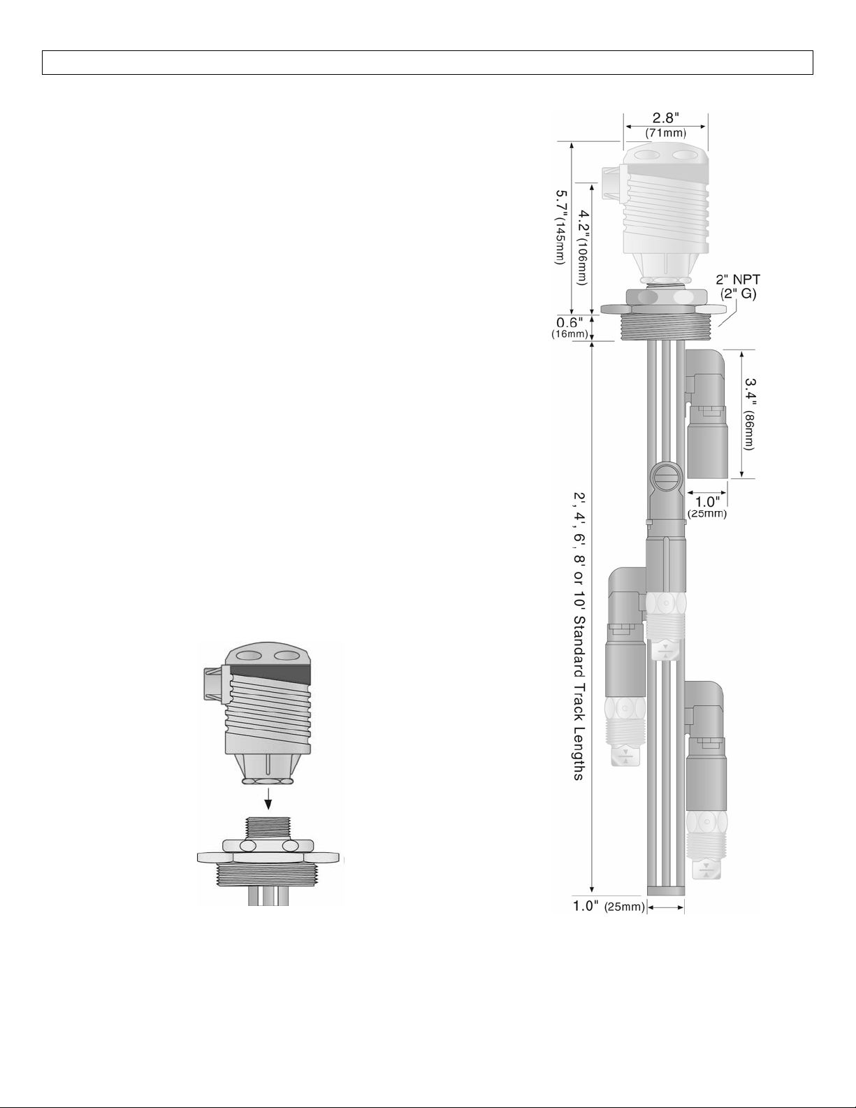
OmegaEngineeringElectricalHousingMountedon
LevelTrackMountingKit
LevelTrackMountingKitSideView
4
Page 5

SAFETYPRECAUTIONS StepThree
AboutThisManual:PLEASE READTHE ENTIREMANUAL PRIORTO INSTALLINGORUSINGTHISPRODUCT.
Thismanual includesinformation ontheLevelTrackKitinstallationfitting fromOmegaEngineering:LVM‐
11, LVM‐12, LVM‐13, LVM‐14 &LVM‐15 Series.Please refer to the part number located on the labelto
verify the exact model which you have purchased.Many aspects of installation and use are similar
betweenmodels.
User’s Responsibility for Safety:OMEGA ENGINEERING manufactures several models of liquid level
sensors, controller and mounting systems.It is the user’s responsibility to select components that are
appropriatefortheapplication,installitproperly,performtestsoftheinstalledsystem,andmaintainall
components.Thefailuretodosocouldresultinpropertydamageorseriousinjury.
Proper Installation and Handling:Use a proper sealant with all installations.Never over tighten the
components.Alwayscheckforleakspriortosystemstart‐up.
MaterialCompatibility:Thetrack,endcap,wire retainerclips,bayonetadapterandsensorcarforall the
LVM‐11/‐12/‐13/‐14/‐15modelsare made of glassfilledPP(Polypropylene, a polyolefin).The sensor car
locking bolt and screw are made of PCTFE (polychlorotrifluoroethylene, a fluoroplastic), the top
compressionfitting,thrust plate, lockingpinand2" NPT fittingaremadeof PP andtheO‐ring is madeof
Viton (a fluorocarbon).The wire gasket is made of Neoprene, the seal plug is madeof Santoprene and
both have a silicon gel for lubrication.Make sure that the application liquids are compatible with the
materialsthatwill be wetted.To determinethechemicalcompatibility between thecomponentsandits
applicationliquids,refertotheCompassCorrosionGuide,availablefromCompassPublications.
Temperature and Pressure:Level Track Kit is designed for use in application temperatures up to 80° C
(176°F).Itisnotdesignedforpressurizedapplicationsduetothewiringthatmusttravelthroughagasket
atthehead.
Wiring and Electrical:Electrical wiring of any liquid level control system should be performed in
accordance with all applicable national, state, and local codes.Take care not to cut or break the outer
insulationjacket ofwiringthat maybeimmersedwhileroutingcablesintheLevel TrackKitsystem.Such
breaksoftheliquidsealofthesensorsystemmayleadtocomponentfailure.
Flammable or Explosive Applications: Level Track Kit may be used within flammable or explosive
applications only if the associated components are rated intrinsically safe for such use.In hazardous
applications,useredundantmeasurementandcontrolpoints,eachhavingadifferentsensingtechnology.
MakeaFail‐SafeSystem:Design afail‐safe systemthataccommodatesthepossibilityofsensororpower
failure.Incriticalapplications,OmegaEngineeringrecommendstheuseofredundantbackupsystemsand
alarmsinadditiontotheprimarysystem.
5
Page 6
ASSEMBLYOFLEVELTRACKKIT StepFour
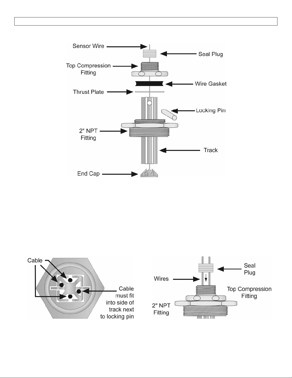
LevelTrackKitAssemblyDrawing(sideview)
Components:OneLevelTrackKit(LVM‐11/‐12/‐13/‐14/‐15)includesthefollowingparts:
1SealPlug 1TopCompressionFitting
1WireGasket 1ThrustPlate
1LockingPin 12”NPTFitting
1Track 1EndCap
2WireRetainerClips(notshown)
Owner’sManual
LevelTrackKitAssemblyDrawing
(TopView)
SealPlugAssemblyDrawing
(SideView)
6
Page 7
ASSEMBLYOFSWITCHCAR StepFive
Sensorcarandbayonetadapter:Thesensor car kit is the heart of the Level Track Mounting Kit system.It
slidesinthegroovesofthetrack,andislockedintopositionbyaplasticboltandscrew.Thebayonetto3/4"
NPT adapter has a female 3/4" NPT fitting on one end where the sensor (not included) will screw in, and a
bayonet fitting on the other end that attaches it onto the sensor car with a slight turn, with an O‐ring in‐
betweentoprovidetensionforthepush‐and‐turnconnection.
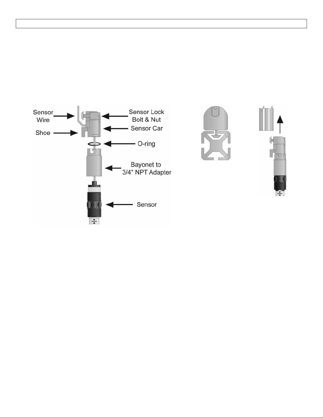
SensorCarKit
AssemblyDrawing
(SideView):
SensorCarKit
toLevelTrackKit
(TopView)
SensorCarKit
toLevelTrackKit
(SideView)
Components:OneSensorCarkit(LVM‐20)includesthefollowingparts:
1LockingBolt 1LockingNut
1SensorCar 1O‐ring
1Bayonetto¾”NPTAdapter
Owner’sManual
7
Page 8

INSTALLATION StepSix
1. Attachthesensor(s)tothesensorcar(s):
a. Threadthesensorwirethroughthebayonettothe¾”NPTadapter,makingtheapproachfrom
thethreadedside.
b. Screw the bayonet adapter onto the sensor until the cap of the sensor seats against the pit
insidetheadapter.
c. Thread the blackO‐ringonto thesensorwire and pushitinto the bayonetsideof the bayonet
adapter,seatingitfirmlyintotheadapter.
d. Thread thesensor wire into the sensor car and out throughthe hole between the sensor car
shoeand
Note:The sensor wire insulation is made from polypropylene or perfluoroalkoxy to ensure chemical
compatibility.Thismakes itstiffer thanconventionalwire.Takecarenottobend thewire toosharply to
the point where the insulation is broken.Such a break could cause liquid to enter the wiring, damaging
thesensor.
e. Pullthesensorwirethroughtheholewhilepushingthesensorandbayonettowardsthesensor
caruntil thebayonetisinposition.Align theslotson thebayonetwith thepineonthesensor
car,andfirmlypushtogether.Whenthe pinisinthecorrectposition,turnthebayonetuntilit
isinthelockedposition.
2. Slidethefirstsensorcarintothetrack:
a. Place the sensor carlocking bolt (with the squaretapered head) through the holeon the flat
sideofthesensorcar,andplacetheslot‐headnutthroughtheotherside.Screwthemtogether
severalturns,butdonottightenthemallthewayyet.
b. Oneendofthetrackhasaholedrilledhorizontallythroughit.Thisisthetopofthetrack.You
willwanttoinsertthesensorcar onthebottomendofthetrack(oppositethehole).Slidethe
bolt of the sensor car into the track (make sure the bolt head is turned so that the beveled
edgesarealignedwiththebevelededgesofthetrack,seeillustrationonpreviouspage).Then
slidetheshoe(thelowerendclosesttothesensor)ofthesensorcarintothetrack.
c. Slide the sensor to the desired position/depth.Tighten the sensor car lock screw with a
screwdriver.Tonot overtighten.Route thewireinsidethetrack.Slidethewireclipsintothe
tracktoholdthewireinthetrack.Donotcutthewiretolengthyet.
Procedurefortwoormoresensors:Ifmorethanonesensorwillbeinstalledonthetrack,repeatthe
proceduresabovefor each sensor.However,donot mountthesensorstoo closely togetherbecause
twosensors ondifferentside ofthetrackcannotfit througha2” NPTfittingatthetop ofthetank.If
adjacent mounting is necessary you may need to install the other sensor in temporary staggered
positions,slidingtheminto the correctpositionafter the Level TrackKitsystem has beenmountedin
thetank.
3. Connectthetracktothetopfitting:
a. Thread the sensor wire(s) through the bottom of the 2” NPT to the Level Track Kit system
fitting.The bottom of the fitting is the side with the smaller threads (2” NPT); it
nearestthesensors.
b. Before actually sliding the fitting onto the track, note the position of the horizontal hole
throughthe track,orient thefittingsothattheslotinthetop ofthefittingwillbealignedwith
thehole.Slidethefittingontothetrack,afewinchesdownfromthetop.
c. Insertthelockingpinintotheholeinthetrack.
thelockingbolt.
should be
i. If there are wires in either or both of the two tracks the locking pin passes through,
makesurethewiresarepinnedintotheinsideslotbythelockingpin(seeillustration).
8
Page 9
INSTALLATION(continued) StepSix
ii. Hint:Startbyinsertingthelockingpinintothetop of the track vertically, parallel with
the wire, thenwhenitsendnears the alignment hole, push the pin in, prying the wire
intotheedgeoftheslotasyoudo.
d. Pullthefittinguptothetopofthetrackuntilthelockingpinisseatedfirmlyintheslotandthe
topofthetrackisflushwiththefitting.
e. Threadthewiresthroughtheholesinthethrustplate.Pushthethrustplatedownuntilitseats
intothetopofthe2”NPTfitting.
f. Threadthe wiresthroughthe slotsinthewiregasket.Push thegasketdownuntilit seatsinto
thetopofthethrustplate.
g. Threadthewiresthroughthe¾”NPTopeningofthetopcompressionfitting,withtheapproach
madefromthelargethreadedside.
h. Screwthetopcompressionfittingontothe2”LevelTrackKitsystemfittinguntilhand‐tight.
i. Threadthewiresthroughtheslotsinthesealplug.Pushthesealplugdownintothetopofthe
¾”NPTopeningonthetopcompressionfittinguntilitseatswiththetopoftheopening.
4. Attachthetermination hardware:Atthispoint,anenclosurehousing(LVCN‐11orLVCN‐12series)or
CompactRelayController(LVCN‐20,LVCN‐100orLVCN‐110series)maybescrewedontothetopofthe
assembly,andwiring attachments made followingtheinstructionsin its manual.Assuming that each
sensorisalready mounted inposition,cutthe sensor wires tothelength approximately 1‐1/2” above
thetopofthehousing.However,besuretomakeallowanceswhencuttingthesensorleadsforfuture
adjustmentstothesensorposition.
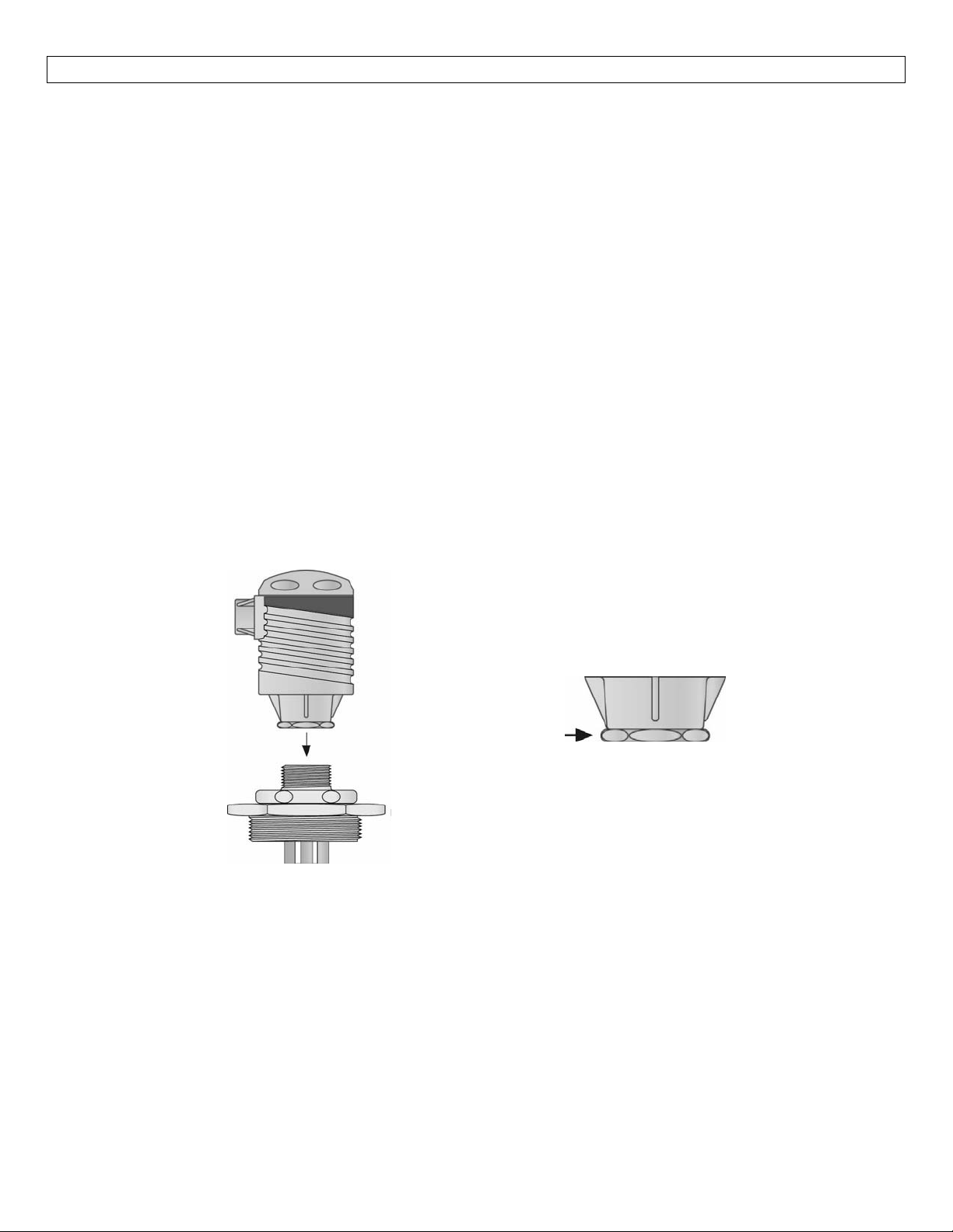
Note:Alwaystighten thecontrollerfrom
the wrench flat located on the swivel
base.Nevertighten from thebodyofthe
controller.
DeterminetheProper Wire Length:Don’tmakethe mistake of trimming the sensor wires too short before
theprocessistested.Ifthesensorsmightneedtobeloweredinthefuture,leavesufficientslackinthewires
toallow forfutureadjust
elsewhereabovethecompressionfitting.
ment.Thisextra wiremay bestoredin thebottomoftheterminal striphousing,or
9
Page 10
INSTALLATION(continued) StepSix
SelectingaLocation:TheLevel TrackKitshouldbemountedverticallyatapointinthetankwhereitwillnot
be exposed to excessive stress (such as radial mixing velocities in excess of 1.5 feet per second).When
mounting in a tank with a mixer, mount the LVM‐11/‐12/‐13/‐14/‐15 series close to the tank wall were
velocitiesarelowest.Choose a mountinglocationwherethe sensorswillfunctioncorrectly (awayfrominlet
pipesthatmaysprayonthesensorscausingfalsereadings)andwherethesensortechnologiesfunctionbest.
It is the user’s responsibility to identify the proper placement and method of installation for the specific
application.
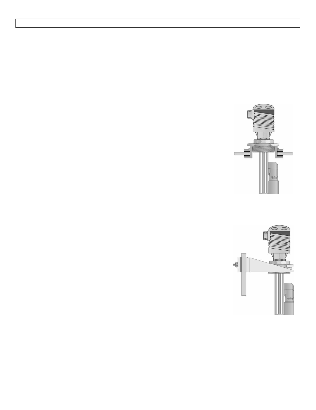
TankTopMounting:
1. Installastandard2” NPTtank adapterthrough thetopofthetankatthe
desiredlocation.Ifthetanktopisnotflat,usea2”NPTself‐aligningtank
adapter.Makesurethethreadsoftheadapterarenotdamagedorworn.
Ifdamaged,useanewadapter.
2. Insertthe assembledLevelTrack Kitsystem throughthetank adapter.If
several sensors are too close together to fit through the tank adapter,
slide them to a different locations so that only one sensor is going
throughtheadapteratatime.
3. To ensure a proper seal, apply an appropriate sealant to the threads of
the Level Track Kit system.Screw the LVM‐11/‐12/‐13/‐14/‐15 series
assemblyintothetankadapter.
4. Makeadjustmentsasrequiredtothesensorposition.
5. Connect the external wiring and conduit to the terminal strip or
controller,followingtheinstructionsinthatmanual.
SideMountBracketMounting:
1. Install the side mount bracket (LVM‐30 series) at the desired location.
Make sure the threads of the bracket are not damaged or worn.If
damaged,useanewbracket.
2. Insert the assembled Level Track Kit system into the bracket.If several
sensorsare tooclosetogether tofitthrough thebracket,slide themtoa
differentlocationssothatonlyonesensorisgoingthroughthebracketat
atime.
3. ScrewtheLVM‐11/‐12/‐13/‐14/‐15seriesassemblyintothebracket.
4. Makeadjustments asrequiredtothesensorposition, andtothebracket
tiltingarm.
5. Connect the external wiring
controller,followingtheinstructionsinthatmanual.
and conduit to the terminal strip or
10
Page 11

11
Page 12

12
 Loading...