

Page 1
LVE 951/952 & 951-B
Electro-Optic Level Switch
M-5173/1112
Instal lati on:
1. Fo r NP T th r ead e d unit s :
a. Use T ef lo n ( T FE ) t h re ad t ape o r P erm atex # 80 72 5 p las t ic pi pe
sea l an t t o s ea l thre a d. Ca u tio n: Pip e s ea lant mu st no t c ome i n co ntac t w i th p ri s m s u rf ace.
b. T h re ad sen sor in t o ta nk w al l and ti g ht en b y ha nd. Fu r the r tig hten
an a d di tion a l on e to t wo th rea ds pa s t ha n d -ti g ht n ess . (Av o id ov er tig h te n ing , a s th i s ma y dama g e t h re ads. )
2. Fo r M1 2 st raig h t t hre a de d un it s:
a. Th rea d sen s or in to t ank wall by ha n d un t il se ns or ho usin g c ontac t s t an k wa l l su rf ac e. ( S e e b elo w fo r ma tin g o-r i ng g la n d d e si gn
inf o rm atio n .)
b. T h e se nso r sha l l be torq ue ti ghte n ed to 12 to 2 4 in -l b ( 1. 4 t o 2. 7
N-m ) . Th i s ra n ge is sl ight l y mo r e th a n “h a nd-t i gh t” to in sur e sea l ing ,
and le s s th an tha t wh i ch wou l d c a us e ho usin g o r th r ead da ma ge.
c. CAU T IO N: Un de r no ci rc um st ance s sh al l th e se ns o r be tigh tene d
mor e th an 1/ 6 tur n bey o nd th at r e qu i red t o s ea t th e bo t tom o f th e
sen s or hou s in g wi t h th e o uts i de wal l of th e ta n k.
3. S ens o r ma y b e in s tal l ed i n h or i zon t al or up to 4 5° fr om ho riz o nt al
pla ne for be st ope r at i on. Ve r ti ca l m ou ntin g is p os si bl e , m ay be dr o pl et s ens i ti ve,
dep end i ng o n vi sc o sit y o f me d ia .
4. Cau tio n : D o n ot ins t al l se n sor cl o se to in f rar e d s our ces or in cand e sc en t l ig ht.
Ref l ec tive su rfac es m a y i nte r fe re w ith prop e r op er a tio n o f th e o pt ic al
sen s or . (Co n su lt Om eg a if p ri sm is to be mo unt e d le s s th an 2” f ro m a ny r efl e ct ive
sur fac e .)
5. Con nec t vo l ta ge s uppl y ( Vdc + 10 %) B et we e n re d (+ ) a nd b la ck ( -) of u ni t.
Cau t io n : D o n ot c o nne c t o utp u t (blu e wi re) to V dc p ow er w i th ou t a lo a d.
See wi r in g di ag ra m s f o r ou tp u t co nf igur a tio n.
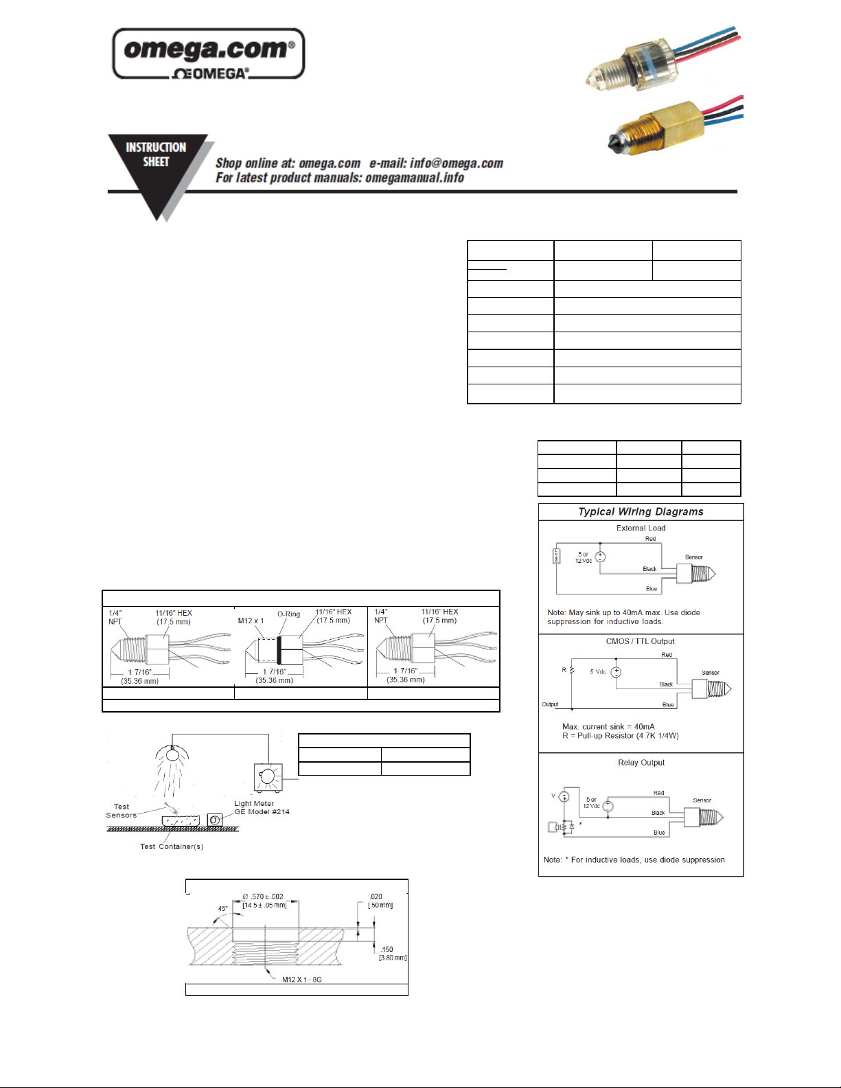
Dimensions
Materials:
Housing and Prism Polysulfone
Operating Pressure 0 to 250 psig, (0 to 17 bar) Max
Operating Temperature -40°F to 230°F (-40°C to 110°C)
Input Voltage 12 VDC ±10%
Current Consumption 12V ~10mA No Load
Output Configuration Open drain may sink 40 mA max.
Repeatability ±1 mm
Ambient Light
Immunity See Ambient Light Test
Note: Not for use in freezing liquids.
Specifications
LVE-951/952 LVE-951B
Nickel plated brass
body with glass prism
Actuation Condition 1/4” NPT M12x1-8
Wet LVE-951 LVE-951-M12
Dry LVE-952 LVE-952-M12
Wet LVE-951-B N/A
LVE-951/952 LVE-951/952-M2 LVE-951-B
Electrical Termination: Lead Wires, 22 AWG, TPE Jacketed, 6” to 8” Extended
Max Ambient Light
Black Container Opaque Container
390 FT-CD 30 FT-CD
Note:
Above testing is based on minimum readings
of at least two (2) samples.
The test depicted to the left was performed to
determine the sensor immunity level to
ambient light. The recorded ambient is the
maximum level at which the sensor performs/
Mating O-Ring Gland Design
M12 x 1 Straight Thread
Page 2
239547 rev B
 Loading...