

Page 1
2
1
Page 2

Page 3

INTRODUCTION/TABLEOFCONTENTS StepOne
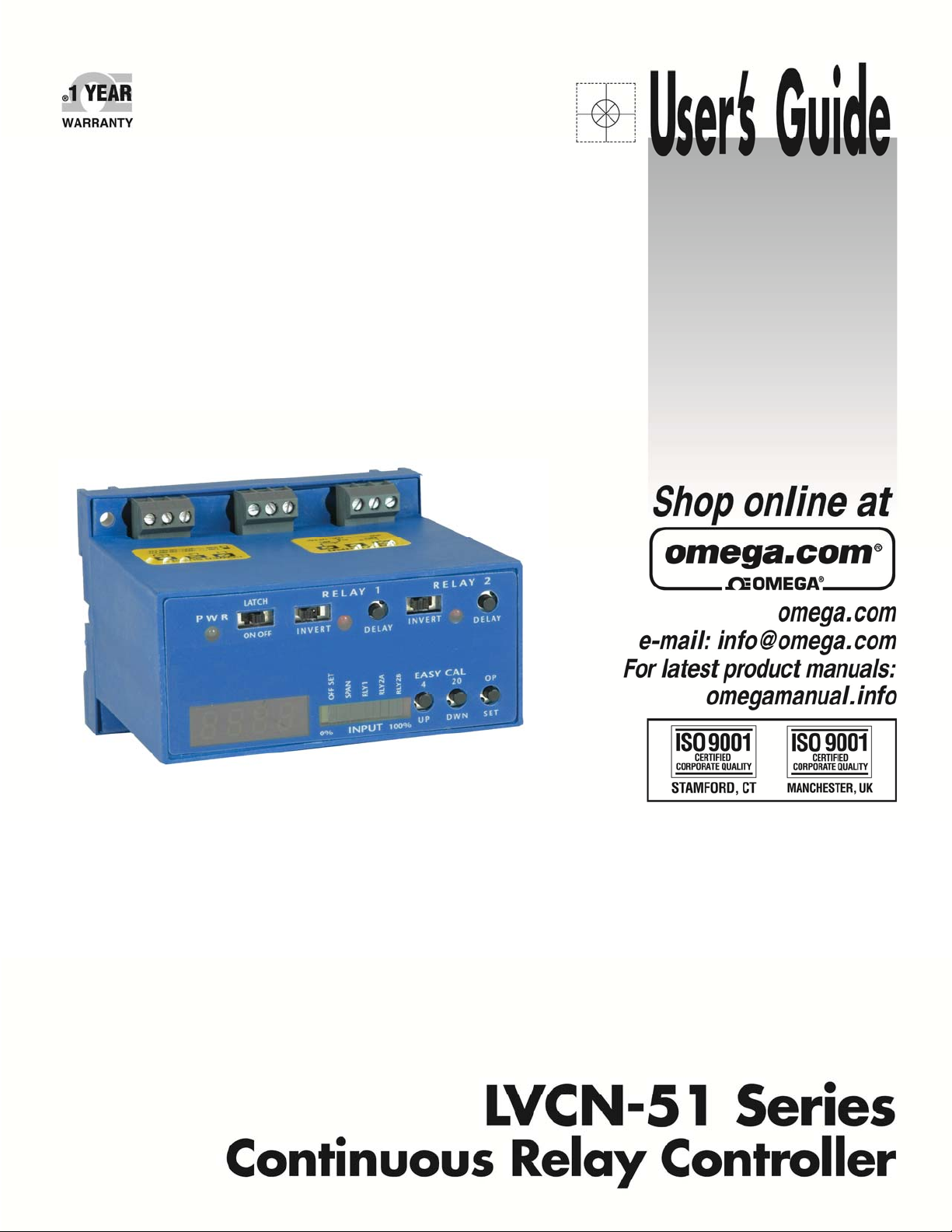
The LVCN‐51 Series Continuous Relay Controller is a general‐purpose levelcontroller which provides single
tank level indication with dual relays and a repeater 4‐20 mA output.The LVCN‐51 Series features both a
single 10A SPDT and a single 10A Latching SPDT relay.This package allows for a system that can perform
automaticoperations(fillor empty) and analarmoperation(highor low).The LVCN‐51 Series canalsobea
controller that can perform dual alarms (2‐high, 2‐low or 1‐high, 1‐low).Package the controller with a
transmitterthatprovidesa4‐20mAoutputandanenclosuretoprotectthecontrollerfromtheelements.
Features
3.5digitLEDdisplayindicateslevelincustomerengineeringunits.
Fail‐Saferelaycontrolofpumps,valvesoralarmswitha0to60seconddelay.
PolypropyleneenclosurecanbeDINrailmountedorbackpanelmounted.
Easysetupwithpushbuttoncalibrationfordisplayandrela
ACpowered
TableofContents
Specifications:.........................................................................................................................................................3
Dimensions:.............................................................................................................................................................3
SafetyPrecautions:.................................................................................................................................................4
MakeaFail‐SafeSystem:............................................................................................................................5
Components:...............................................................................................................................................5
Installation:............................................................................................................................................................5
GettingStarted:.......................................................................................................................................................6
FeaturesoftheSingleInputHighorLowAlarmRelay:..............................................................................6
FeaturesoftheLatchingRelay(AutomaticFillorEmpty):.........................................................................6
GuidetoControls:.......................................................................................................................................7
Electrical:.................................................................................................................................................................8
WiringtoInputTerminals:.........................................................................................................................8
SettingInputPolarity:.................................................................................................................................9
RepeaterOutput:........................................................................................................................................9
VACPowerInputWiring:.........................................................................................................................10
Changingfrom120to240VAC:...............................................................................................................10
RelayInputWiring:...............................................................................................................................
ApplicationExmaples:...........................................................................................................................................11
LowLevelAlarm:.......................................................................................................................................11
HighLevelAlarm:......................................................................................................................................11
AutomaticFill:...........................................................................................................................................12
AutomaticEmpty:.....................................................................................................................................12
Programming:......................................................................................................................................................13
Appendix:..............................................................................................................................................................14
ControllerLogic:........................................................................................................................................14
RelayLatchingLogicTab
FactoryReset:...........................................................................................................................................14
LockoutFunction:.....................................................................................................................................16
Troubleshooting:.......................................................................................................................................15
Exercise:...............................................................................................................................................................16
le:.......................................................................................................................14
ysettings.
....10
3
Page 4
SPECIFICATIONS/DIMENSIONS StepTwo
Displaytype: LED,3.5digit
Displayunits: Engineering
Displayoutput: 0to999or0.0to199.9
LEDindicators: Powerandrelaystatus
Bargraphdisplay: 4‐20mAwithsetpoints
Configuration: Pushbutton
Alarmindication: Amber:<4mA
Red:>20mA
Security: Lockoutmode
Sensorinput: (1)4‐20mAtransmitter
Supplyvoltage: Selectable120VAC/240VAC
50‐60Hz.
Consumption: 5Wattmaximum
Sensorsupply: 24VDC@1.5Watts
Looppower: 4‐20mA,18VDC
Contacttype: (1)SPDT
(1)LatchedSPDT
Contactrating: 250VAC,10A
Contactoutput: Selectable,NOorNC
Contactlatch: ONorOFF
Contactconfiguration: 1:Highorlowlevelalarm
2:Highandlowlevelalarm
3:Automaticfillorempty
4:Automaticfilloremptywithalarm
Contactdelay: 0‐60seconds
Failsafety: Powerfail‐safe
Repeateroutput: 4‐20mA,12‐36VDC
Ambienttemperature: F:‐40°to158°
C:‐40°to70°
Enclosuretype: 35mmDIN(EN50022)
Enclosurematerial: Polypropylene
(U.L.94VO)
CECompliance: EN50082‐2immunity
EN55011emission
EN61010‐1Safety
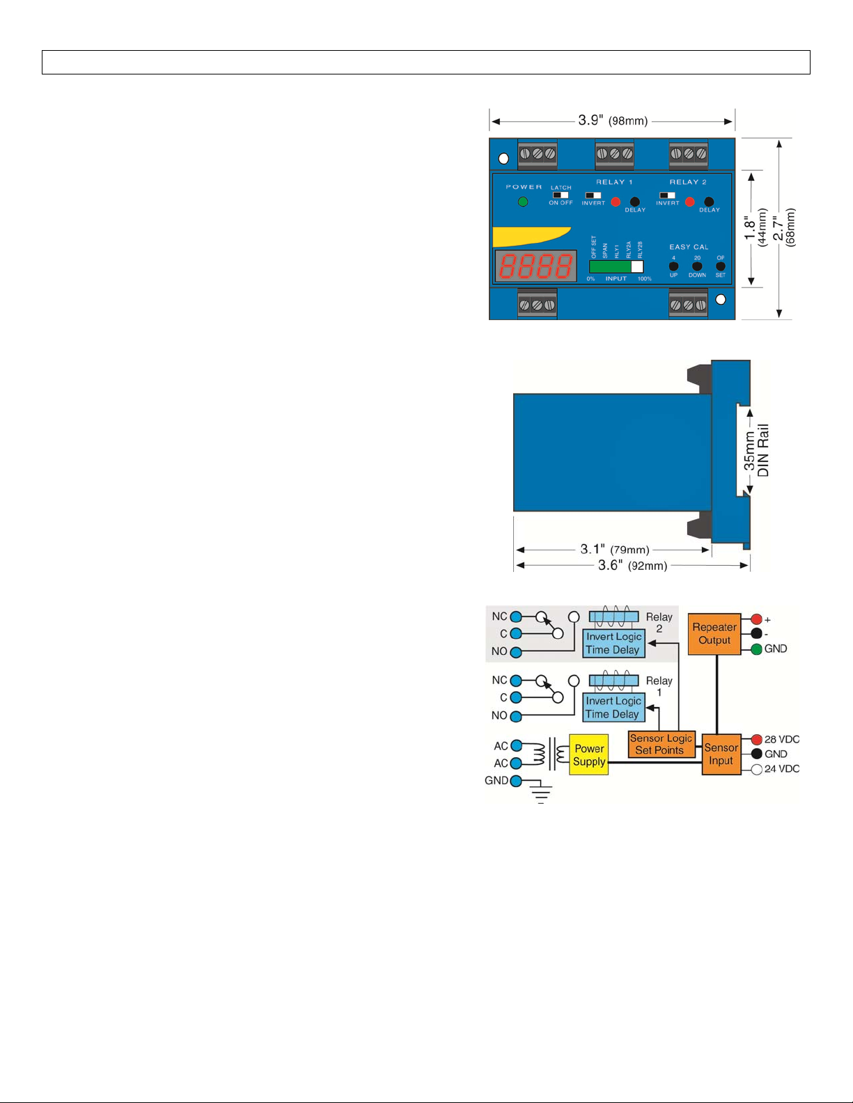
TopView‐AllModels
SideView‐AllModels
InternalControllerLogic
4
Page 5

SAFETYPRECAUTIONS StepThree
About ThisManual:PLEASEREADTHEENTIREMANUALPRIORTOINSTALLING ORUSING THISPRODUCT.
ThismanualincludesinformationonthecontinuousrelaycontrollerfromOMEGAENGINEERING:LVCN‐51
series.
User’s ResponsibilityforSafety:OMEGAENGINEERINGmanufacturesseveralmodelsofcontroller, with
differentmountingandswitchingconfigurations.Itistheuser’sresponsibilitytoselectacontrollermodel
that is appropriate for the application, install it properly, perform tests of the installed system, and
maintainallcomponents.
Electrical Shock Hazard:It is possible to contact components on the controller that carry high voltage,
causing serious injury or death.All power to the controller and the relay circuit(s)it controls should be
turned OFF prior to working on the controller.If it is necessary to make adjustments during powered
operation,use extremecautionanduse onlyinsulatedtools.Makingadjustmentstopoweredcontrollers
isnotrecommended.Wiringshouldbeperformedbyqualifiedpersonnelinaccordancewithallapplicable
national,stateandlocalelectricalcodes.
FlammableorExplosiveApplications:TheLVCN‐51Series continuousrelay controllersshouldnotbeused
withexplosiveorflammableliquids,whichrequireanintrinsicallysafeorexplosionproofrating.Ifyouare
unsure of the suitability of a controller for your installation, consult your Omega Engineering
representativeforfurtherinformation.
InstallInaDryLocation:Thecontrollerhousingisnotdesignedtobeimmersed.Wheninstalledproperly,
itshouldbemountedin such a way thatitdoesnotnormallycome into contact with liquid.Refer to an
industryreferencetoensurethatcompoundsthatmaysplashontothecontrollerhousingwillnotdamage
it.Suchdamageisnotcoveredbythewarranty.
Relay ContactRating:Therelayisrated fora10 ampresistive load.Manyloads(such asa motorduring
start‐uporincandescentlights) arereactiveandmayhaveaninrushcurrentcharacteristicthatmaybe10
to 20 times their steady‐state load rating.The use of a contact protection circuit may be necessary for
yourinstallationifthe10ampratingdoesnotprovideanamplemarginforsuchinrushcurrents.Incritical
applications,redundantbackupsystems andalarms mustbeusedinadditiontotheprimarysystem.Such
backupsystemsshouldusedifferentsensortechnologieswherepossible.
5
Page 6
SAFETYPRECAUTIONS/INSTALLATION StepThree
Make a Fail‐Safe System: Design a fail‐safe system that accommodates the possibility of relay or power
failure.If power is cut off to the controller, it will de‐energize the relay.Make sure that the de‐energized
stateoftherelayisthesafestateinyourprocess.Forexample,ifcontrollerpowerislost,apumpfillingatank
willturnoffifitisconnectedtotheNormallyOpensideoftherelay.
While the internal relay is reliable, over the course of time relay failure is possible in two modes: under a
heavyload thecontacts maybe“welded”orstuck intothe energizedposition,orcorrosionmaybuildupon a
contact so that it will not complete the circuit when it should.In critical applications, redundant backup
systems and alarms must be used in addition to the primary system.Such backup systems should use
differentsensortechnologieswherepossible.
While this manual offers some examples and suggestions to help explain the operation of OMEGA
ENGINEERINGproducts, suchexamplesare forinformationonly andarenot intendedasa completeguideto
installinganyspecificsystem.
Components:
LVCN‐51 ‐Singleinputwithdualrelays,3.5digitLEDdisplayandrepeateroutput.
LVCN‐51‐CE ‐Singleinputwithdualrelays,3.5digitLEDdisplayandrepeateroutputwithCEapproval.
Owner’sManual
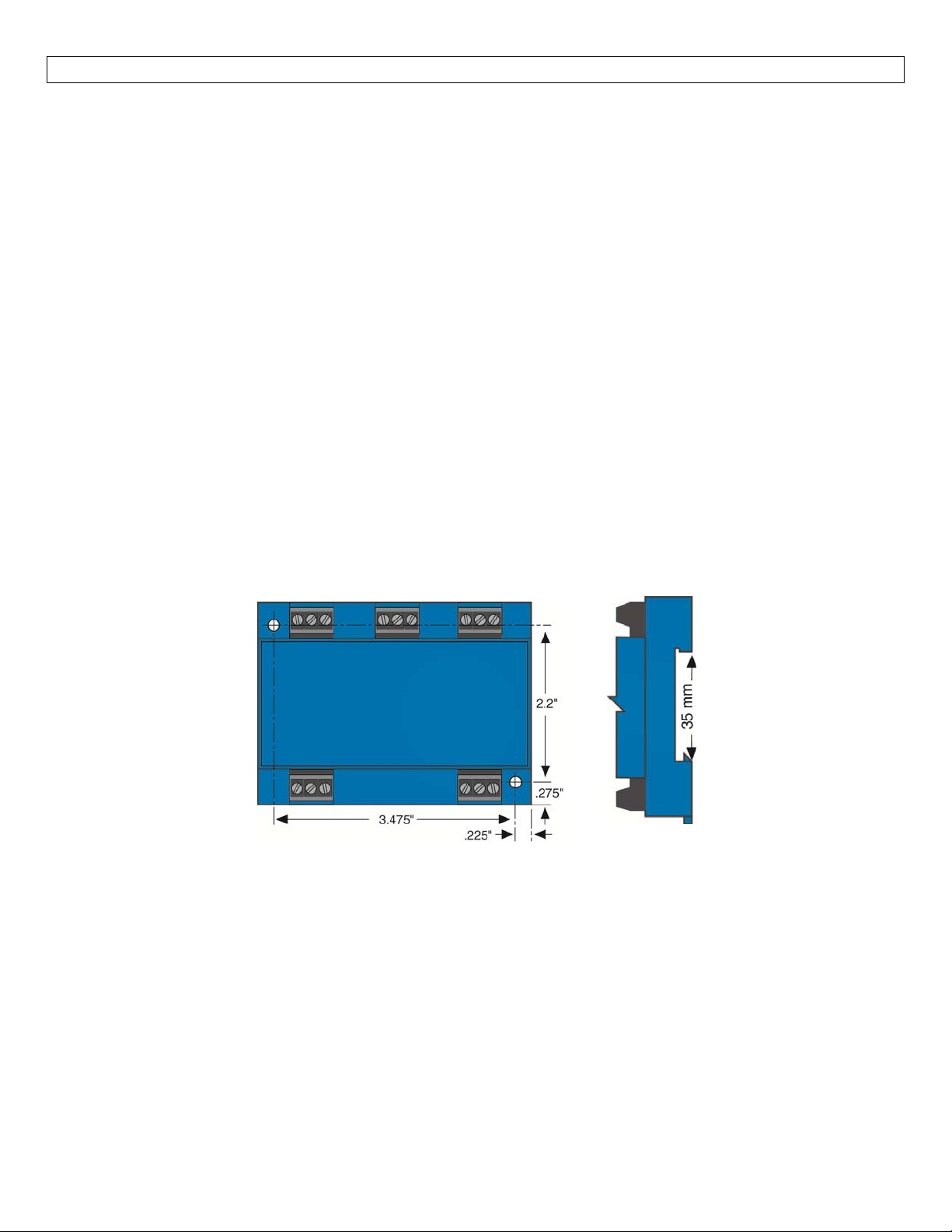
PanelDINRailMounting:Thecontrollermaybemountedbyeitheraback panel using two screws through
mountingholeslocatedatthecornersofthecontrollerorbysnappingthecontrolleron35mmDINRail.
Note:Alwaysinstallthecontrollerinalocationwhereitdoesnotcomeintocontactwithliquid.
6
Page 7
GETTINGSTARTED StepFour
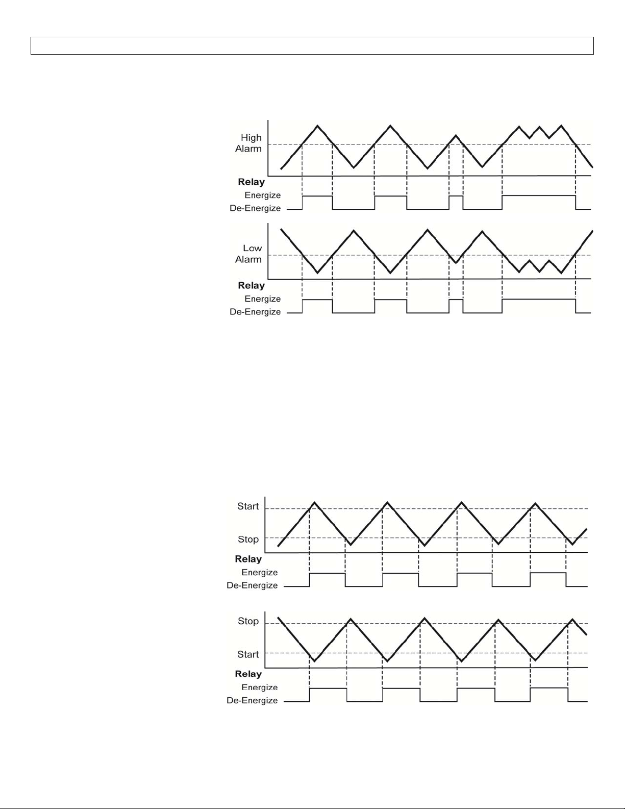
FeaturesofaSingleInputHighorLowRelay:SingleInputRelays(Relay1orRelay2w/latchturnedOFF)are
designedtoswitchfroma singleset‐point.ItturnsitsinternalrelayONorOFF(assetbytheinvertswitch)in
responsetothepresenceofliquid,andchangestherelaystatusbackagainwhenthesensorisdry.
High Alarm:Invert is OFF.
Relay will energize when the
levelrises abovethe highalarm
setting and will de‐energize
when it drops below the high
alarmsetting.
LowAlarm:InvertisON.Relay
will energize when the level
drops below the low alarm
setting and will de‐energize
when it rises above the low
alarmsetting.
Singleinputhighorlowrelaysmaybeusedwithanydevicethatoutputsa4‐20mAsignal.Therelayisasingle
pole, double throw type; the controlled device can be connected to either the normally open or normally
closedsideoftherelay.Atimedelayfrom0to60secondscanbesetbeforetherelayrespondstothesensor
input.Typicalapplicationsforsingleinputrelaysarehighlevelorlowlevelswitch/alarmoperations(opening
a drain valve whenever liquid level rises to a set‐point) and over‐flow protection (turning off a pump or
soundinganalarmwhenahighlevelisreached).
FeaturesofaLatchingRelay(automaticfillorempty):Thelatchingrelay(relay2only)isdesignedtoswitcha
relay on and off at two different levels.It turns its internal relay ON or OFF (as set by the invert switch) in
responsewhenthelevelisabovethehighsettingorbelow thelowsetting.Therelaywillnotchangeitsstate
whenthelevelisbetweenthehighandlowsetting.
AutomaticEmpty:
Latch is ON & Invert is OFF.Relay
will energize when level reaches
high setting (both settings are
submersed).Relaywillde‐energize
when level is below the bottom
setting(bothsettingsaredry).
AutomaticEmpty:
Latch is ON & Invert is ON.Relay
will energize when level is below
the bottom setting (both switches
are dry).Relay will de‐energize
when level is above the high
setting(bothsettingsarewet).
7
Page 8
GETTINGSTARTED(continued) StepFour
The Latching Relay (Automatic Fill/Empty) may beusedwith any device that outputs a 4‐20 mA signal.The
relayis asinglepole,doublethrowtype;thecontrolleddevicecan beconnectedtoeitherthe normallyopen
ornormallyclosed sideoftherelay.Typical applicationsforLatching Relays areautomaticfilling (starting fill
pump at a lowlevel and stopping pump at a high level) or automatic emptying operations (opening a drain
valveatahighlevelandclosingvalveatlowlevel).
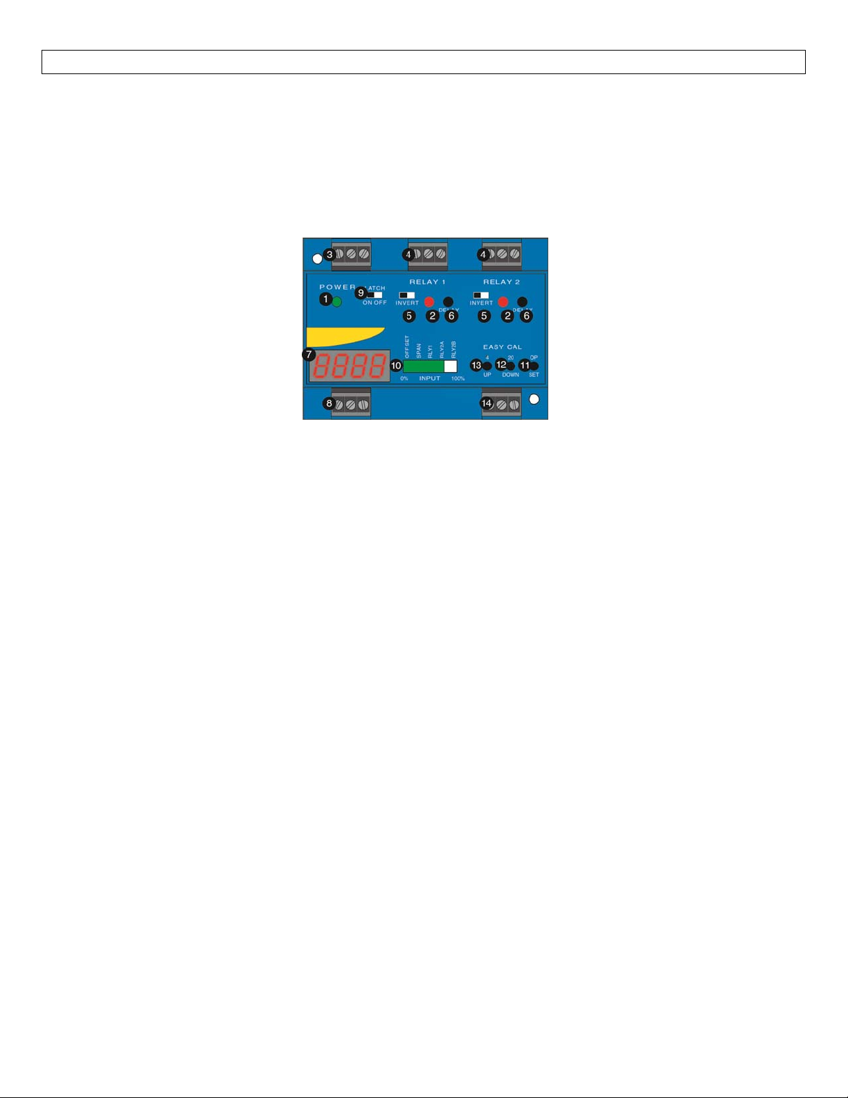
GuidetoControls:Belowisalistingandthelocationofthedifferentcomponentsforthecontroller:
1. Powerindicator:ThisGreenLEDlightswhenACpowerisON.
2. Relay indicator:This Red LED will light whenever the controller energizes the relay, in response to the
transmitterinputandafterthetimedelay.
3. ACPowerterminals:Connectionof120VACpowertothecontroller.Thesettingmaybechangedto240
VAC if desired.This requires changing internal jumpers; this is covered in the Installation section of the
manual.Polarity(neutralandhot)doesnotmatter.
4. Relay terminals (NC, C, NO):Connect the device you wish to control (pump, alarm etc.) to these
terminals: supply to the COM terminal, and the device to the NO or NC terminal as required.The
switcheddeviceshould be anon‐inductiveloadofnot more than10amps;for reactive loads thecurrent
must be derated or protection circuits used.When the red LED is ON and the relay is in the energized
state,theNOterminalwillbeclosedandtheNCterminalwillbeopen.
5. Invertswitch:Thisswitchreversesthelogic oftherelay controlinresponse totheswitch(es): conditions
thatusedtoenergizetherelaywillnowde‐energizetherelayandviceversa.
6. Timedelay:Setsdelayfrom0to60
7. Digitaldisplay:Showsthecurrent4‐20mAsignalinengineeringunits.
8. Input terminals:Connect the transmitter wires to these terminals:A 24 VDC power is provided for
currentloopwithanadditional28VDCpowerterminalifrequired.
9. Latchswitch (relay2):Thisswitchdetermineshow therelaywillbeenergizedinresponse tothetwoset
points.WhenLATCH isOFF, therelayresponds tosetpoint RLY2Aonly;whenLATCHis ON,therelaywill
energiz
orbothdry).Therelaywillremainlatcheduntilbothsetpointschangeconditions.
10. BarGraph:Displays4‐20mAsignalasapercentageoftherange.
11. OP/SET:Usedtoscrollbetweensetpointsdurin
12. 20/Down:UsedtodecreasedisplayvalueduringprogrammingandforEasyCal™Spansetup.
13. 4/Up:UsedtoincreasedisplayvalueduringprogrammingandforEasyCal™Offsetsetup.
14. RepeaterOutput:Isolatedterminalwhichreproducesthe input4‐20mAsignal.Terminalrequires12
VDCpowerforoperation.
eorde‐energizeonlywhenbothsetpoints(RLY2AandRLY2B)areinthesamecondition(bothwet
seconds.HoldDelaybuttontoincreasedelayin5secondincrements.
gprogramming.
‐36
8
Page 9
ELECTRICAL StepFive
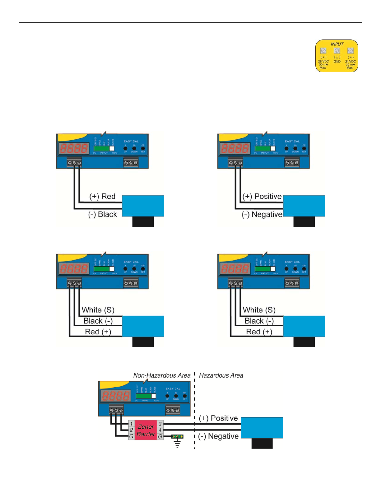
WiringtoInput Terminals:Signalinputis alwaysthroughthe 24VDCterminal.The 28VDC
terminal is used as an alternative power supply for three‐wire devices.Please note a
difference between 2‐wire and 3‐wire level transmitters and sourcing and sinking modes
below.Below is a quick review of wiring the LVCN‐51 Series to common 4‐20 mA
transmitters.
LVCN‐2700Series(LVU2710,LUV2718,LVU2726&
LVU2732)&LVCN414Series(LVCN414,LNCV414‐
I,LVCN210&LVCN318)
Sourcingmode(FactorySetting)
LVU800Series(LVU809,LVU816,LVU826&
LVU832)
SourcingMode(FactorySetting)
LVU‐300Series(LVU‐301only)
SourcingMode(FactorySetting)
UltrasonicLevelTransmitter(IntrinsicallySafe)(LVU‐201Aonly)
Sinkingmode(internaljumpermustbechanged)
LVU‐300Series(LVU‐303only)
Sinkingmode(internaljumpermustbechanged)
9
Page 10
ELECTRICAL(continued) StepFive
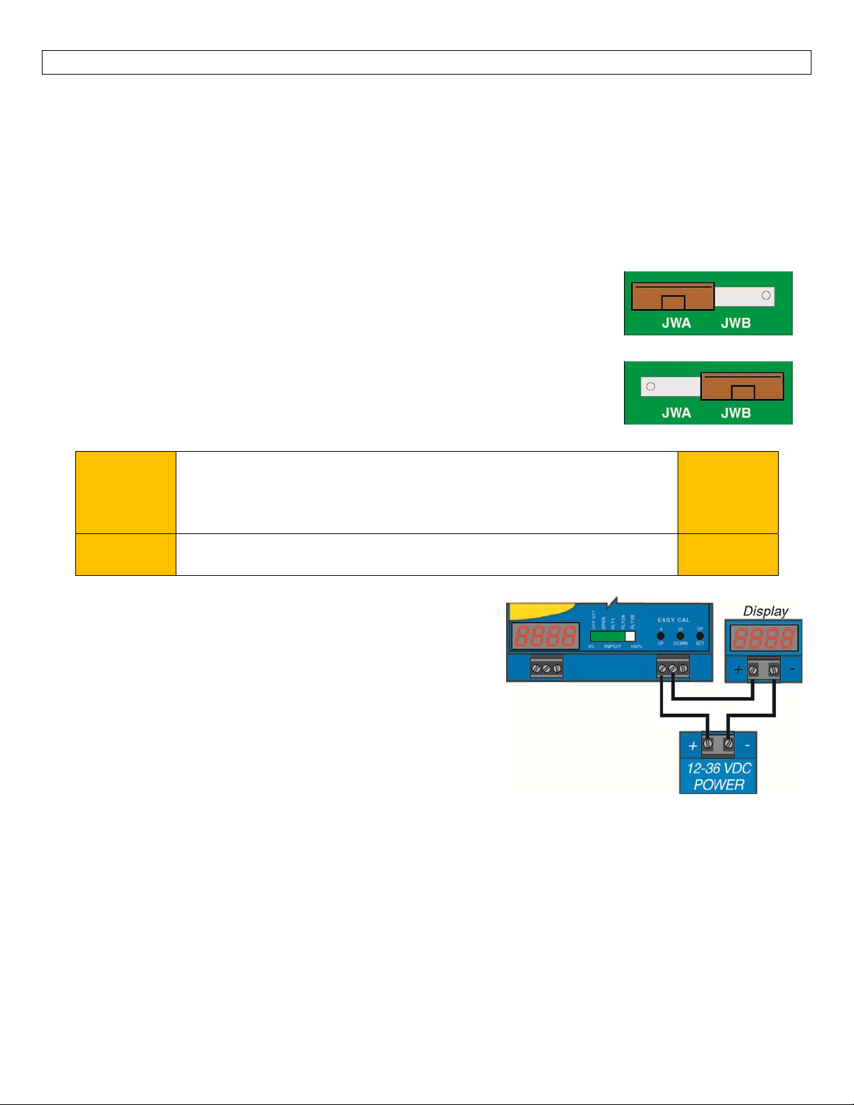
Setting Input Polarity (Sourcing vs. Sinking modes):The LVCN‐51 Series can be set in one of two modes,
sourcingandsinking.TheLVCN‐51Seriesisshippedfromthefactoryinthesourcingmode.Thisiscompatible
withany looppoweredtransmitter suchasthe LVCN‐2700Series(LVU2710, LUV2718,LVU2726& LVU2732),
LVU800 Series (LVU809, LVU816, LVU826 & LVU832), LVCN414 Series (LVCN414, LNCV414‐I, LVCN210 &
LVCN318)andthethree‐wireUltrasonicLVU‐300Series(LVU‐301only)withnoadjustmentrequired.Ifusing
aLVU‐300Series(LVU‐303 only) or Ultrasonic LevelTransmitter(IntrinsicallySafe)(LVU‐201Aonly), follow
theinstructionsbelow.
1. Removetheback panelofthe controllerandgently slidetheprinted
circuit
board(PCB)fromthehousing.UsecautionwhenremovingthePCB.
2. LocatejumpersJWAandJWBonthePCB.
3. Tochangefrom sourcingto sinking,removejumperfromJWAandplaceon
JWB.TheLVCN‐51
Seriesis shipped fromthefactoryinthe sourcing mode
(JWAactive).
4. GentlyreturnPCBintohousingandreplacebackpanel.
Note:Looppowereddevicescanoperateineitherthesouringorsinkingmodes.
LVCN‐2700Series(LVU2710,LUV2718,LVU2726&LVU2732),LVU800
NoChange
Required
Series(LVU809,LVU816,LVU826&LVU832),LVCN414Series
(LVCN414,LNCV414‐I,LVCN210&LVCN318)andthethree‐wire
UltrasonicLVU‐300Series(LVU‐301only)
Change
Required
UltrasonicLevelTransmitter(IntrinsicallySafe)(LVU‐201Aonly)
LVU‐300Series(LVU‐303only)or
RepeaterOutput:The isolatedrepeateroutputreproducesthe
input4‐20mAcurrentsignal.Thissignalcanberepeatedtoany
other device that accepts a 4‐20 mA input, suchasaPLC,DCS,
SCADA, chart recorder or another display.The repeated 4‐20
mAsignalisnotanexcitedoutput.Anexternalpowersupplyis
required and should not exceed a maximum of 36 VDC.See
the wiring diagram to the right for instructions in wiring all
threecomponents(repeateroutput,powersupply andthe new
device)inserieswitheachother.
SourcingMode
SinkingMode
Sinkingor
Loop
Devices
Sourcing
Devices
10
Page 11
ELECTRICAL(continued) StepFive
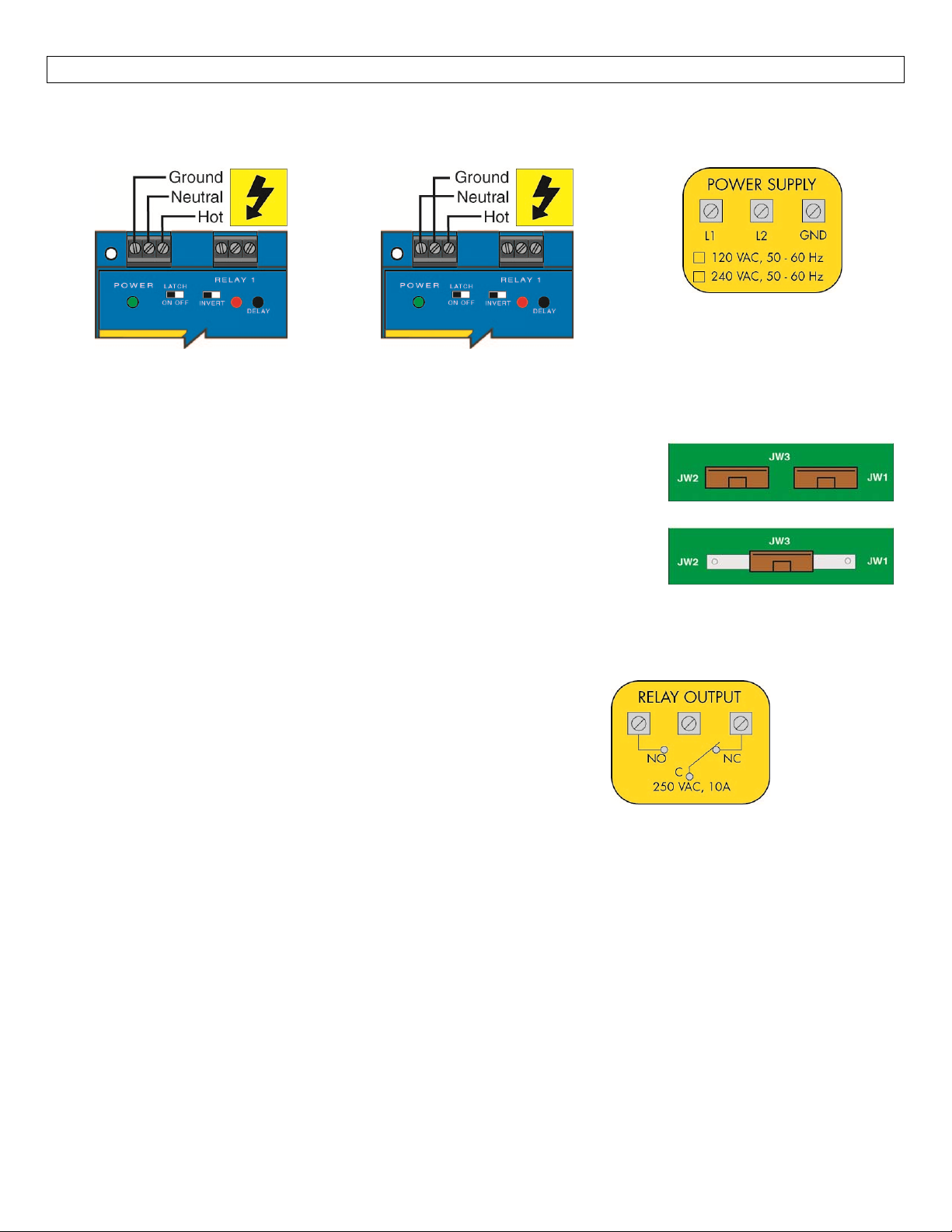
VACPowerInputWiring:Observe the POWER SUPPLY label ontheLVCN‐51Series.Thelabelidentifies the
power requirement (120 or 240 VAC) and the terminal wiring.Note: Polarity does not matter with the AC
inputterminal.
Changing from 120 to 240 VAC:The LVCN‐51 Series is shipped from the factory configured as a 120 VAC
powereddevice.
1. Remove the back panel of the controller and gently slide the printed
Toswitchto240VAC,followtheinstructionsbelow.
120VACJumperSetting
circuitboard(PCB) from the housing.Use cautionwhenremovingthe
PCB.
2. LocatejumpersJWAandJWBonthePCB.
3. To change from sourcing to sinking, remove jumper from
JWA and
240VACJumperSetting
place on JWB.The LVCN‐51 SERIES is shipped from thefactoryin the
sourcingmode(JWAactive).
4. GentlyreturnPCBintohousingandreplacebackpanel.
RelayInput Wiring:Therelay isa singlepole,double
throwtyperated at 250VoltsAC,10 Amps.The two
terminal NO and NC (normally open and normally
closed) will be used in different applications.
Remember that the "normal" state is when the relay
coilisde‐energizedandthe Red re
layLEDis Off/de‐
energized.
11
Page 12
APPLICATIONEXAMPLES StepSeven
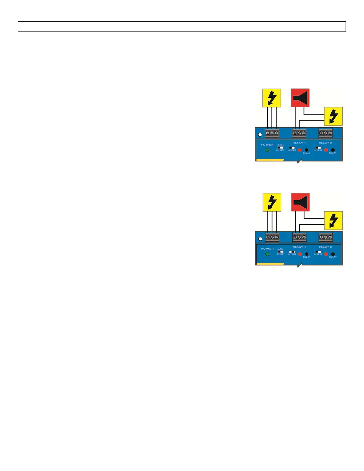
LowLevelAlarm:Thegoalistomakesurethatthe liquidlevel doesnot fallbelow acertainpoint.Ifitdoes,
analarmissupposedtosound,alertingtheoperatorofalowlevelcondition.
Ifpowerisaccidentallycuttothecontroller,thesensor'sabilitytonotifytheoperatorofalowlevelcondition
couldbelost.Thesystemmustalerttheoperatornotonlytolowliquidlevel,buttocontrollerpowerloss.
To do this, connect the hot lead of the alarm to the NC side of the relay
terminalofthecontroller.Ifpowerislost,therelaywillbede‐energized,and
the alarm will sound (if there is still power to the alarm circuit itself).The
alarm circuit should have a non‐interruptible power supply or some other
indicatororbackupalarmtowarnofapowerfailureinthealarmcircuit.
In this application, the normal status of the sensor at the bottom if thetank
will be wet, and the relay will be energized holding the alarm circuit open.
Both the relay LED and the Input LED will be on simultaneously, so for this
application,InvertshouldbesettotheOFFposition.
HighLevelAlarm:In the samemanor,thissystem can beusedto sound analarmwhenfluid reachesahigh
level, with just a change in the location of the sensor andthe setting of the
Invertswitch.
The alarm is still connected to the NC side of the relay to allow for a power
failurealarm.
The sensor is normally dry.In this condition, we want the relay to be
energized so the alarm does not sound: i.e., the Red relay LED should be on
whenevertheInputLEDisAmber.SoweturnInvertOn.Ifthefluidlevelrises
tothehighsensorpoint,thesensorgoes on, the relay de‐energizes,andthe
alarmsounds.
12
Page 13
APPLICATIONEXAMPLES(cont.) StepSeven
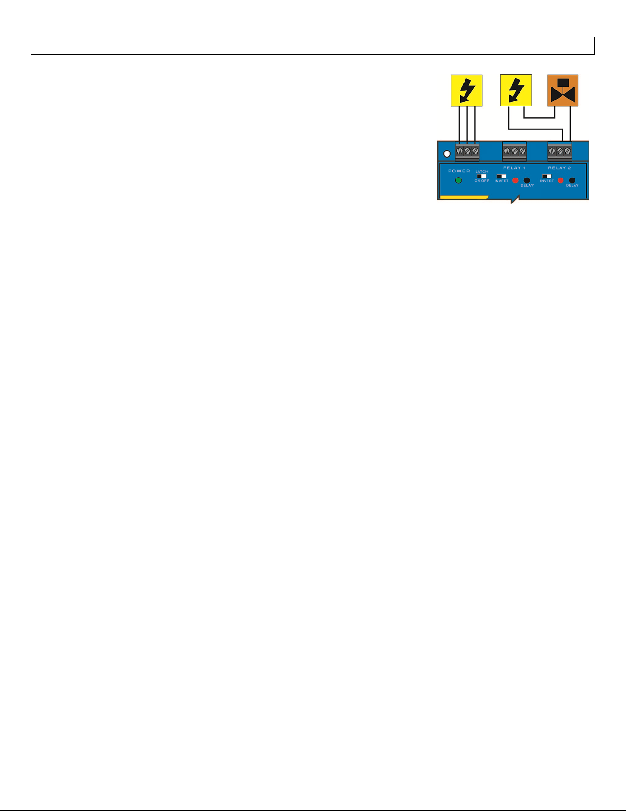
Automatic Fill:This system consists of a tank with a valve controller by the
LVCN‐51 Series.At a low set point, the valve opens, filling the tank.At the
high set point, the valve closes.Part of a proper fail‐safe design for this
particularsystemisthatifpowerislost to the controller for any reason,the
valvefillingthetankmustclose.Therefore,we connect the valve to the NO
sideof therelay.Whentherelayisenergized,thevalvewillopenand fillthe
tank.Therelay indicatorwill corresponddirectlytotheOpen/Closestatusof
thevalve.
NOTE: If the device’s load exceeds the rating of the controller’s relay, a
stepperrelayofhighercapacitymustbeusedaspartofthesystemdesign.
DeterminingthesettingsofLATCHandINVERT:Thisisthewaythesystemmustoperate:
Whentheliquidlevelisbelowthelowsetpoint,thevalveshouldopen,startingtofillthetank.
Whentheliquidisabovethelowsetpoint,thevalvewillremainopen.
Whentheliquidreachesthehighsetpoint,thevalveshouldclose.
Latch:Inanytwo‐sensorcontrolsystem,LATCHmustbeON.
Invert:Referringto thelogicchartinStepNine, welookforthe settingthatwill de‐energizetherelay (valve
close)whenbothinputsarewet.Inthissystem,InvertshouldbeON.
AutomaticEmpty:Inthesamemanner,thecontrollercanbeusedtoautomaticallyemptyatankwithjusta
changetothesettingoftheINVERTswitch:
• ThevalveisstillconnectedtotheNOsideoftherelaytoallowforapowerfailurefail‐safecondition.
• Thenormalstateofthevalveisclosed.Inthisstate,wewanttherelaytobeenergizedatthehighset
point(openingvalvetodraintank).Therelaywillde‐energizeatthelowsetpoint(closingvalve).
Note:Afail‐safe design isimportant.Ifthe tank isbeingpassivelyfilled, andavalvemust be usedtoactively
emptyit,apowerfailuretoeitherthecontrollerorthepumpcircuitswillcauseoverflow.
13
Page 14
PROGRAMMING StepEight
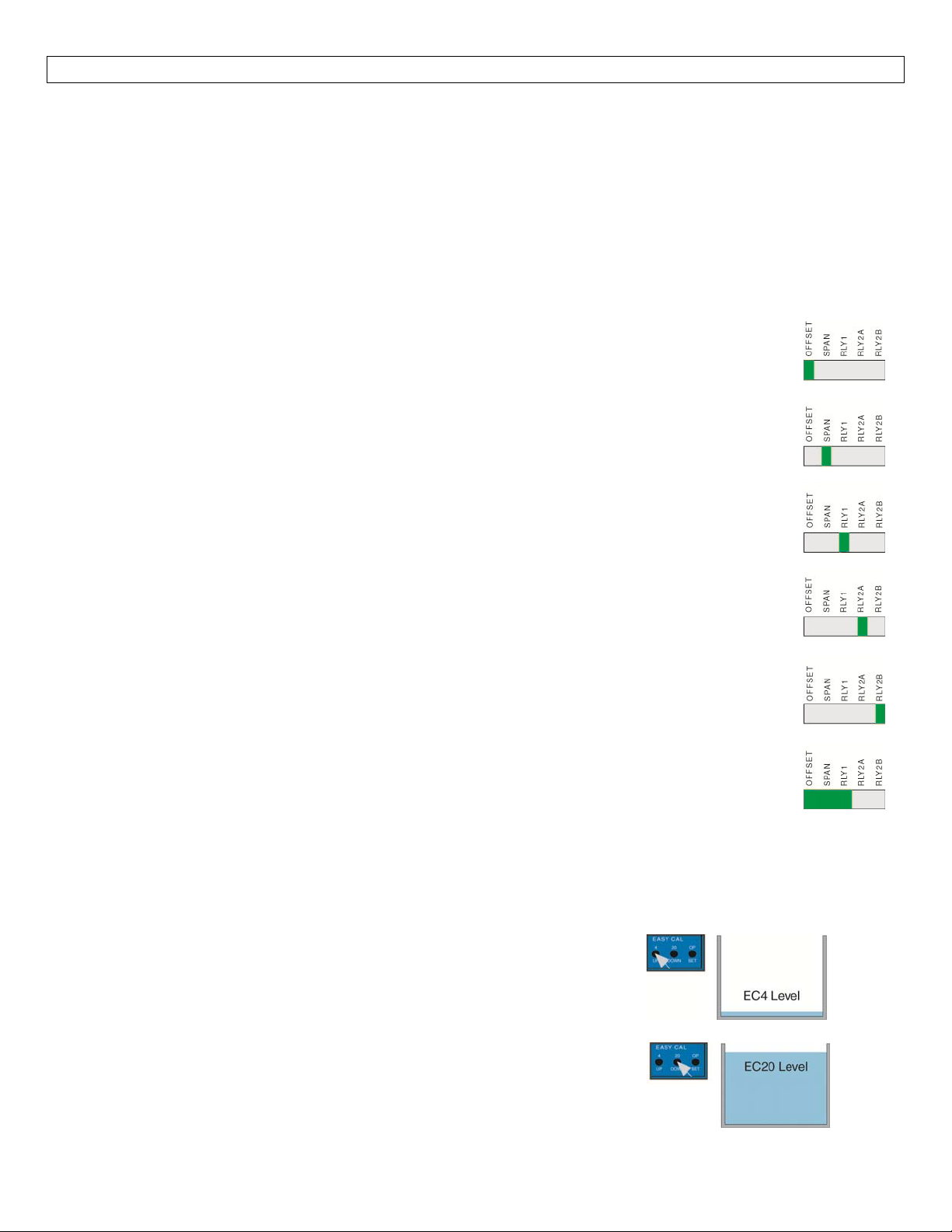
OFFSET:Equivalenttothe4mAsetpointonthetransmitter.Enterthevalueyouwouldliketoseewhenthe
LVCN‐51Seriesreceives4mA.
SPAN:Equivalenttothe20mAsetpointonthetransmitter.Enterthevalueyouwouldliketoseewhenthe
LVCN‐51Seriesreceives20mA.
RLY1,RLY2A,RLY2B:Setpoints
Settingvalues:WiththeLatchOff,ignoresteps9and10.RLY2Bwillnotshowduringtheprogramming
sectionwithLatchOff.
1. PresstheSETbuttononce.Immediately,theLEDbargraphwillbegintoflashone
Greenbarnex
2. UseUP/DWNbuttonstochangedisplaytothedesiredOFFSETvalue.
3. PresstheSETbuttonagain.Immediately,theLEDbargraphwilljumponeGreenbarto
therightnexttoSPAN.
4. UseUP/DWNbuttonstochangedisplaytothedesiredSPANvalue.
5. PresstheSETbuttonagain.Immediately,theLEDbargraphwilljumponeGreenbarto
therightnexttoRLY1.
6. UseUP/DWNbuttonstochangedisplaytothedesiredRLY1value.
7. PresstheSETbuttonagain.Immediately,theLEDbargraphwilljumponeGreenbarto
therightnexttoRLY2A.
8. UseUP/DWNbuttonstochangedisplaytothedesiredRLY2Avalue.
9. PresstheSETbuttonagain.Immediately,theLEDbargraphwilljumponeGreenbarto
therightnexttoRLY2B.
10. UseUP/DWNbuttonstochangedisplaytothedesiredRLY2Bvalue.
ttoOFFSET.
forRelays.ValuesmustbebetweenOFFSETandSPAN.
11. PresstheSETbuttonagain.Immediately,theLEDbargraphwillreturnbacktoit
normaloperationofsolidbars.
EasyCalCalibration:TheOffsetandSpanpoints may be programmed directly to a specificleve
These are the EasyCal 4 (Empty tank) and EasyCal 20 (Full tank) values.Note: the level of the tank must
physicallybeatitsdesiredlevelwhenusingEasyCal.Ifnot,the EasyCalwillacceptthelevelandthevalueson
thedisplaywillbeincorrect.Usethefactoryresettostartoverifthisoccurs.
To calibrate EC4, set the tank to the new Offset level.Press [4]
buttononceand [E]will appearinthedisplay. Press[4]buttonagain
and[C]willappearinthedisplayandEC4isset.
To calibrate EC20, set the tank to the new Span level. Pr
buttononceand[E]willappearinthedisplay.Press[20]buttonagain
and[C]willappearinthedisplayandEC20isset.
14
ess [20]
linthetank.
Page 15
APPENDIX StepNine
ControllerLogic:Pleaseusethefollowingguidetounderstandtheoperationofthecontrollers.
1. PowerLED:MakesuretheGreenpowerLEDisONwhenpowerissuppliedtothecontroller.
2. BarGraphLED:Thebargraph LED on the controller willalwaysindicatethe proportional 4‐20 mA input
signalgoingtotheLVCN‐51Seriescontroller.i.e.:ifthetankis25%full,then25%ofthebargraphwillbe
litGreen.Ifa single Amber barappears,this indicates aninputcurrentof less than4mA.Ifa single Red
LED appears, this indicates an input current greater than 20 mA.Use this feature to confirm the input
signalfortheLVCN‐51Series.
3. RelayLEDs:ThenormalstateoftherelayiswhentheLEDisOFF.Whentherelaybecomesenergized,the
RedLED willlight.Ifpower isremovedfrom thecontroller,the relaywillreturn tothenormal state(LED
OFF).
4. Display:Willindicatetheproportionalleveloftheliquidbaseduponthe4‐20mAinput.IfEasyCalisused
foreithertheemptytanklevel,fulltanklevelorboth,the displaywillignorethe4‐20mAinputsignaland
usetheEasyCalsettingasitsemptyand/orfullposition.
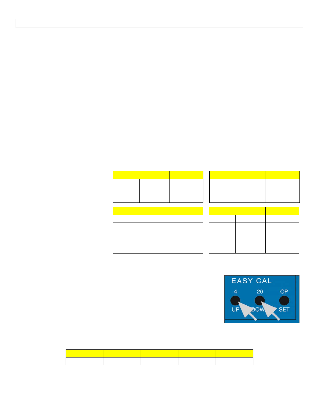
RelayLatchLogicTable(relay2only):
Therelaycaneitherbeanindependentrelay(highorlowlevelalarm)
orcanbealatchingrelay(automaticfillorempty)with latchON.With LatchOFF,therelaywillonlyrespond
totheRLY2Asetting.RLY2Bwillbeignored.
WithLatchOFF,thesettingforRLY
2Bwillbeignored.
Allchangesto
the relay’s state will occur from
theRLY2Asetting.
With Latch ON, the relay will
actuate when the level is above
RLY2AandRLY2B.Therelaywill
not change its condition if the
level is between RLY 2A and RLY
2B.Therelay willreverseitsstate
InvertOFF LatchOFF
RLY2A RLY2B Relay
ON
OFF
NoEffect
NoEffect
InvertOFF LatchON
RLY2A RLY2B Relay
ON
OFF
ON
OFF
ON
ON
OFF
OFF
NoChange
NoChange
ON
OFF
ON
OFF
InvertON LatchOFF
RLY2A RLY2B Relay
ON
OFF
NoEffect
NoEffect
InvertON LatchON
RLY2A RLY2B Relay
ON
OFF
ON
OFF
ON
ON
OFF
OFF
NoChange
NoChange
OFF
ON
OFF
ON
when the level is below both RLY
2AandRLY2Bsettings.
Factory Reset:Returns the LVCN‐51 Series to its original factory settings,
includingsettingtheOFFSETto4 mA and the SPAN to 20 mA.Toperforma
FactoryReset, first removepowerto the controller.Holdboththe 4/UP and
20/DWN buttons while adding power to the LVCN‐51 Series.An “F” for
Factory Reset will appear in the display indication the Factory Reset was
achieved.If an “E” for Error appears, the Factory Reset was not performed
and you will need to try again.Note: make sure both buttons are pressed
whileaddingpower.The“E”willappearifonlyoneofthebuttonsispressed.
Factory
SettingsforLVCN‐51Series
OFFSET SPAN RLY1 RLY2A RLY2B
4.0 20.0 6.0 18.0 8.0
15
Page 16
APPENDIX(continued) StepNine
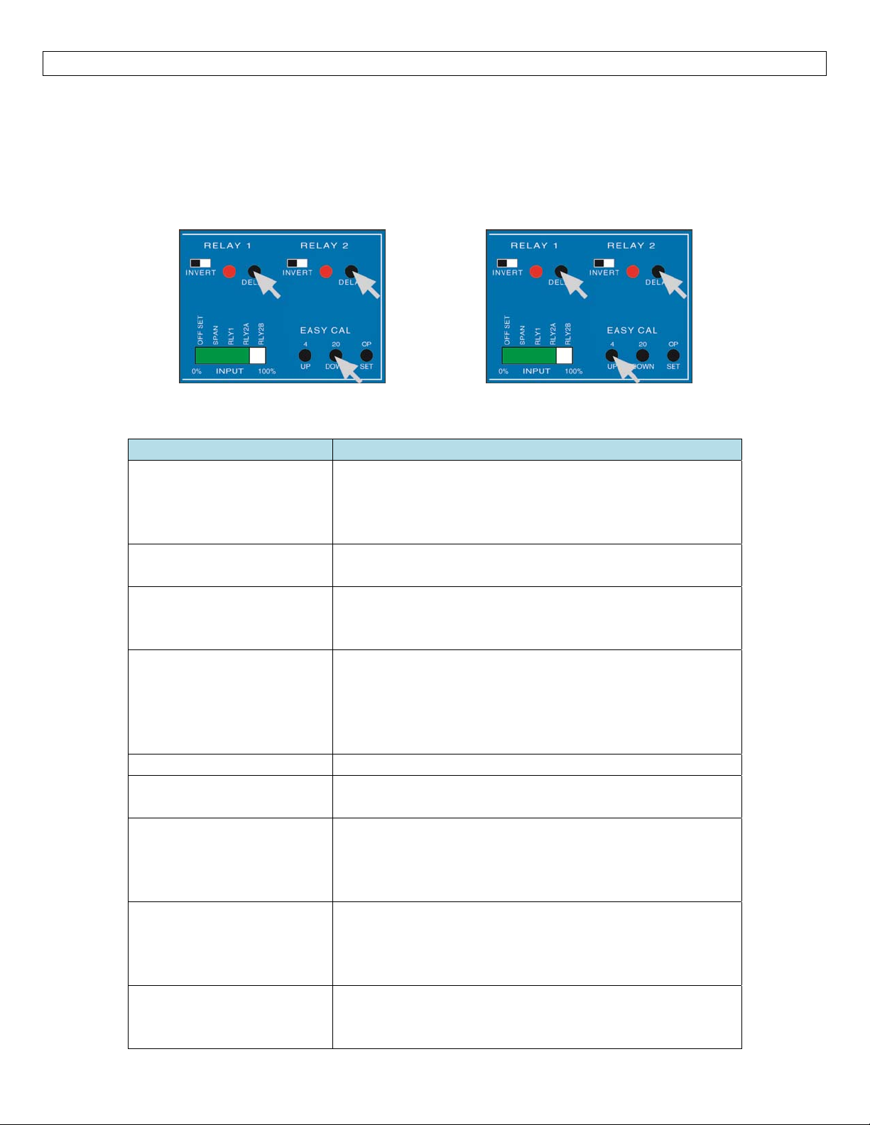
LockOutFunction:ThebuttonsonthefaceoftheLVCN‐51Seriescanbedisengagedorlockedout.To
lockoutthebuttons,pressbothdelaybuttonsandtheDWNbuttonsimultaneously(seebelowleft).Thiswill
lockoutallofthebuttonsandpreventanaccidentalchangingofsettings.Tounlockthebuttons,pressboth
delaybuttonsandtheUPbuttonsimultaneously(seebelowright).
Troubleshooting
Displayisnotreading
correctlevel.
BarGraphisnotindicating
thecorrectlevel.
BarGraphshowsasingle
Amberbar.
BarGraphshowsasingle
Redbar.
RLY2Bdoesnotappear. FlipLatchswitchtoON.
Relayswitchesonlyfrom
RLY2A(ignoresRLY2B).
LevelreachesalarmON,
butrelayisOFF.
PumporValveissupposed
tostop,butitdoesnot.
Controllerispowered,but
nothinghappens.
LockOutON
(LOCKED)
PROBLEM SOLUTION
First check the Bar Graph to make sure it is indicating
the correct level.If not, check transmitter.If so,
performa factoryresetontheLVCN‐51Seriesandreset
values.
Checkthetransmitter’s4‐20mAoutputmakingsureitis
spannedcorrectlyfortheapplication.
This indicates a currentinputless than 4mA.Check for
looseoropen wiresbetween thetransmitterandLVCN‐
51Seriesandchecktheoutputofthetransmitter.
This indicates a current input greater than 20mA.
Remove power immediately.Check for a short in the
wiring between the transmitter and LVCN‐51 Series or
for some other power source that is affecting the input
loop.
LatchisturnedOFF.FlipthelatchswitchtoturnON.
First, check to make sure the input LED is ON.If not,
checkwiringtosensor.
Second, check status of Relay LED.If incorrect, flip the
Invertswitchtochangetherelaystate.
First,checkto make surethebargraphis indicating the
correct level.Next check the relay settings. Finally,
check status of Relay LED.If incorrect, flip the Invert
switchtochangetherelaystate.
First check the Power LED to make sure it is Green.If
not,checkthewiring,powerandmakesuretheterminal
isseatedcorrectly.
LockOutOFF
(UNLOCKED)
16
Page 17
EXERCISE StepTen
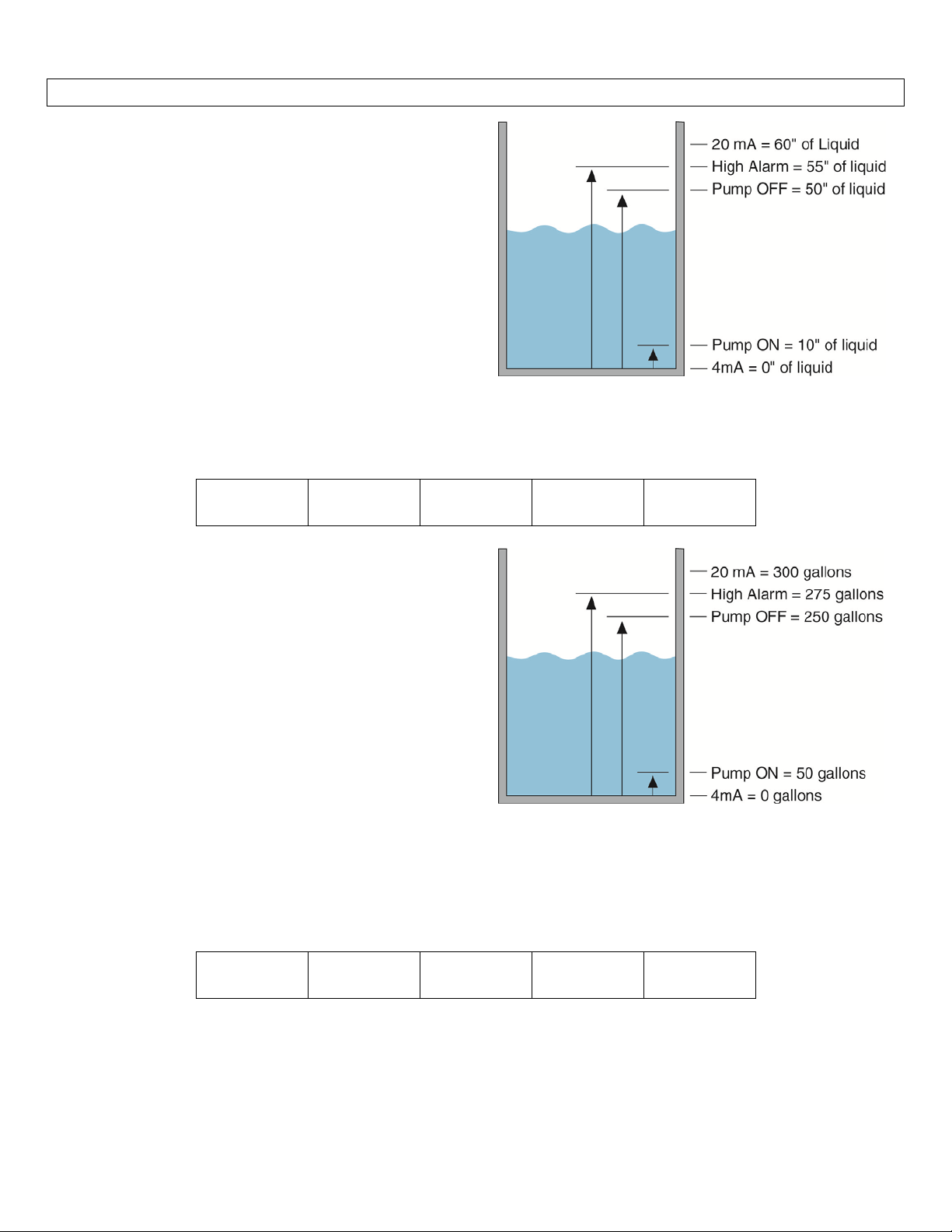
The following exercise demonstrates inventory
control with automatic filling and a high level alarm.
The usable range is 60 inches of liquid.The pump
starts filling at 10 inches of liquid and stops filling at
50 inches of liquid.A high level alarm occurs at 55
inchesofliquid.
EnterallvaluesintotheLVCN‐51Seriesininches.The
OFFSET is the corresponding 4 mA setting in inches.
The SPAN is the corresponding 20mA setting in
inches.RLY2Aand RLY2Bisdedicatedtothe fillingof
the tank because RELAY2 is a latching relay.RLY1 is
dedicatedtothehighlevelalarmbecauseitisasingle
set point relay.
programmingtheLVCN‐51Series.
The next exercise demonstrates the same inventory
control with automatic filling and a high level alarm.
However,theunitshavebeenchangesfrominchesto
gallons.Within the tank, 1” = 50 gallons of liquid.
The usable range is now 300 gallons of liquid.The
pump starts filling at 50 gallons of liquid and stops
filling at 250 gallons of liquid.A high level alarm
occursat275gallonsofliquid.
Use the following values for
OFFSET
0.0
SPAN
60.0
RLY1
55.0
RLY2A
50.0
RLY2B
10.0
Enter all values into the LVCN‐51 Series in gallons.
The OFFSET is the corresponding 4 mA setting in
gallons.TheSPANisthecorresponding20mAsetting
ingallons.RLY2AandRLY2Bisdedicatedtothefilling
ofthetankbecauseRELAY2isalatchingrelay.
dedicatedtothehighlevelalarmbecauseitisasingle
set point relay.Use the following values for
programmingtheLVCN‐51Series.
OFFSET
0
17
SPAN
300
RLY1is
RLY1
275
RLY2A
250
RLY2B
50
Page 18
EXERCISE(continued) StepTen
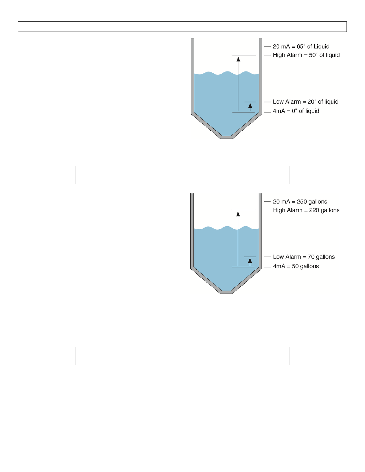
The following exercise demonstrates inventory
control with a high and low level alarm.The usable
rangeisbetween16and56inchesofliquid.Thehigh
level alarm occurs at 50 inches of liquid and the low
levelalarmoccursat20"ofliquid.
EnterallvaluesintotheLVCN‐51Seriesininches.The
OFFSET is the corresponding 4mA setting in inches.
The SPAN is the corresponding 20mA setting in
inches.RLY1 is dedicated to the high level alarm
because it is a single set point relay.RLY2A is
dedicated to the low level alarm because the latch is
turned off on Relay 2.Use the following valu
programmingtheLVCN‐51Series.
OFFSET
0.0
The next exercise demonstrates the same inventory
controlwithahighandlowlevelalarm.However,the
units have been changes from inches to gallons.
Alongthestraightside of the tank, 1”=50gallonsof
liquid.The usable range is now from 50 to 250
gallons of liquid.The high level alarm occurs at 220
gallons of liquid.The low level alarm occurs at 70
gallonsofliquid.
SPAN
65.0
es for
RLY1
50.0
RLY2A
20.0
RLY2B
N/A
EnterallvaluesintotheLVCN‐51Seriesingallons.
TheOFFSETisthecorresponding4mAsettingin
gallons.TheSPANisthecorresponding20mAsetting
ingallons.RLY1isdedicatedtothehighlevelalarm
becauseitisasinglesetpointrelay.RLY2Ais
dedicatedtothelowlevelalarmbecausethelatchis
turnedoffonRelay2.Usethefollowingvaluesfor
programmingtheLC52‐1001.
OFFSET
0
SPAN
250
RLY1
220
RLY2A
70
RLY2B
N/A
18
Page 19

19
Page 20

20
 Loading...