

Page 1
®
LVCN4300 & LVCN400 Series
Capacitive Level Measurement
Page 2

®
Page 3

Contents
Introduction .................................................4
Models & Dimensions .........................................5
Wiring Diagram ..............................................6
Installation ..................................................8
Calibration .................................................10
Handling ..................................................11
Technical Specifications ......................................12
Trouble Shooting ............................................13
www.omega.com e-mail: [email protected]
03
Page 4
Introduction
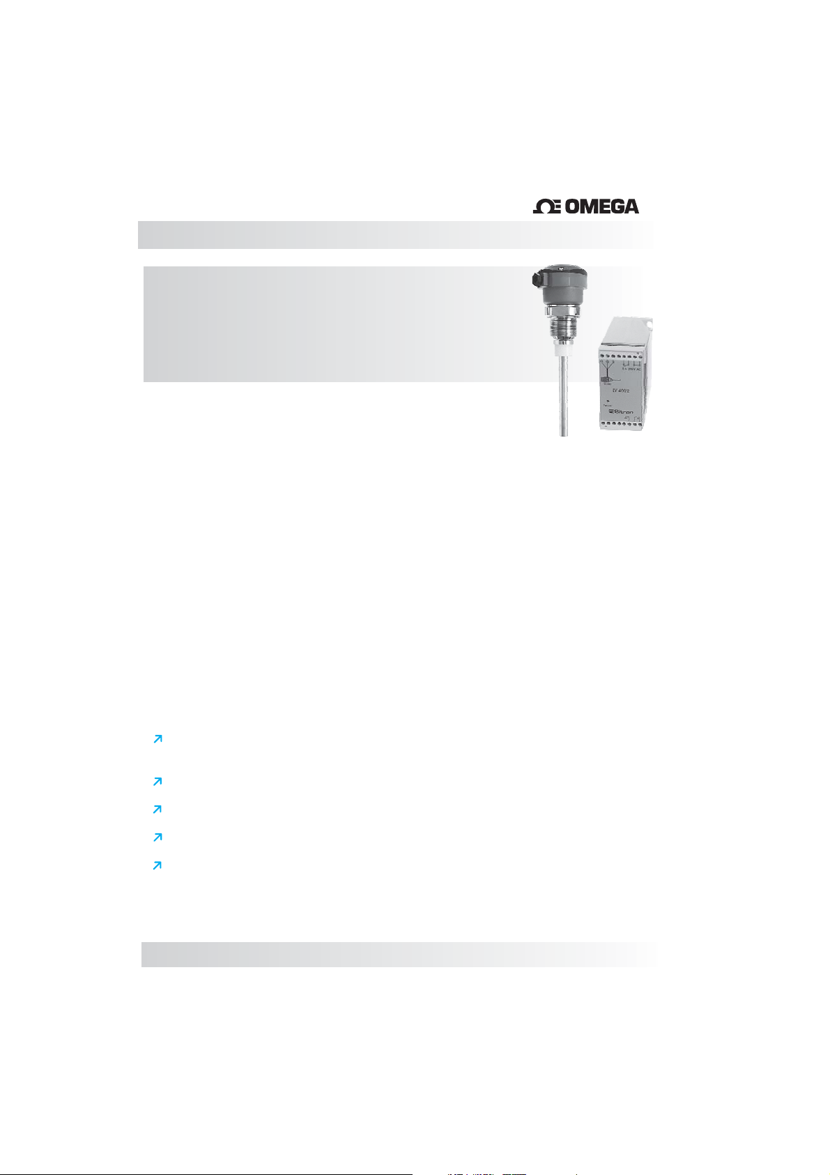
LVCN4300 - Capacitive Point
Level Sensor
LVCN400 Series - Relay Controllers
The LVCN4300 Series, together with the LVCN400 Series Relay
Controllers are designed to detect the level of a wide variety of solids
and liquids, including both conductive and non-conductive materials.
®
Because of its all 316SS construction the is typically
specified for high temperature or high pressure applications, or for
appications requiring extremely high mechanical resistance in such
products as cement, sand, coal, grains, etc. When supplied with Halar
coated active sensing tip, the can be applied in corrosive or
aggressive mediums.
Made of 316 Stainless Steel, the LVCN4300 is available with various
types of process connections such as threaded, flange or sanitary.
Custom connections available upon request.
The LVCN400 Series can be ordered for varying supply voltages;
24Vdc ( , 110Vac or 220Vac with an
SPDT relay output.
LVCN401) (LVCN402) (LVCN403)
LVCN4300
LVCN4300
Features
Wide range of applications/industries:
I.e. water, oils, corrosives, solids, powders, grains, etc.
Accurate and reliable measurement
No moving parts - Rugged construction
Can operate at high temperatures and pressure
Functions on conductive as well as non-conductive mediums
04
Page 5
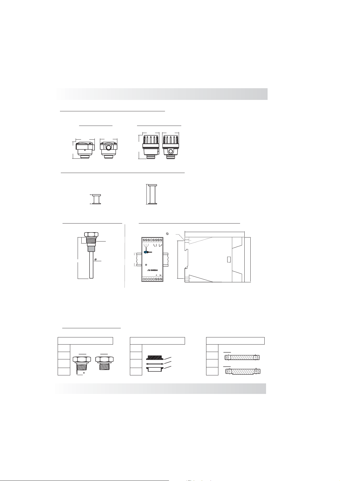
Mounting Options for LVCN4300
Models & Dimension
Nylon Housing
89mm
76mm
80mm
Aluminium Housing
89mm
126mm
89mm
Extended Necks for High Temperature
50mm
Extended necks for medium (up to 120°C) and high temperature (up to 150°C)temperature
LVCN4300 Standard
1”NPT
20
L
L= Insertion length
½”
100mm
LVCN400 Series Relay Controllers
6mm
35mm
1
+
234567
_
S
LVCN401
Power
8
5a250VAC
69.8mm
®
1591113141210 16
111mm
84mm
Note: Insertion Lengths greater than 150mm will require the balance to be ordered with a
non-active portion of that insertion length. This can affect how coatings can be ordered
with this model.
Process Connections
Tri-Clamp Flange
2”
TC Connection
Rubber Seal
Process Connection
3”
1”
1½”
2”
2½”
FF
RF
3/4”
1”
1½”
2”
Threaded
NPT
1,75
BSP
1½”
2½”
www.omega.com e-mail: [email protected]
ANSI 150#
ANSI 300#
05
Page 6
Wiring Diagram
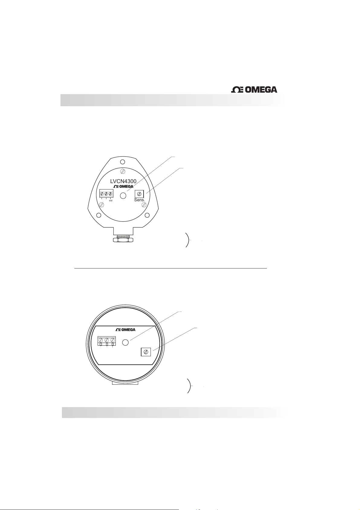
LVCN4300- Nylon Housing
®
(L1) LED: Indicates Level Detection
(P1) Sensitivity Adjustment
LVCN4300
3
2
1
_
out
+
®
Sens.
1- Positive
2- Negative
3- Out
LVCN4300 - Aluminum Housing
®
2
3
1
_
out
+
LVCN4300
on
Sens.
Connection to the LVCN400 Controller
(L1) LED: Indicates Level Detection
(P1) Sensitivity Adjustment
06
1- Positive
2- Negative
3- Out
Connection to the LVCN400 Controller
Page 7
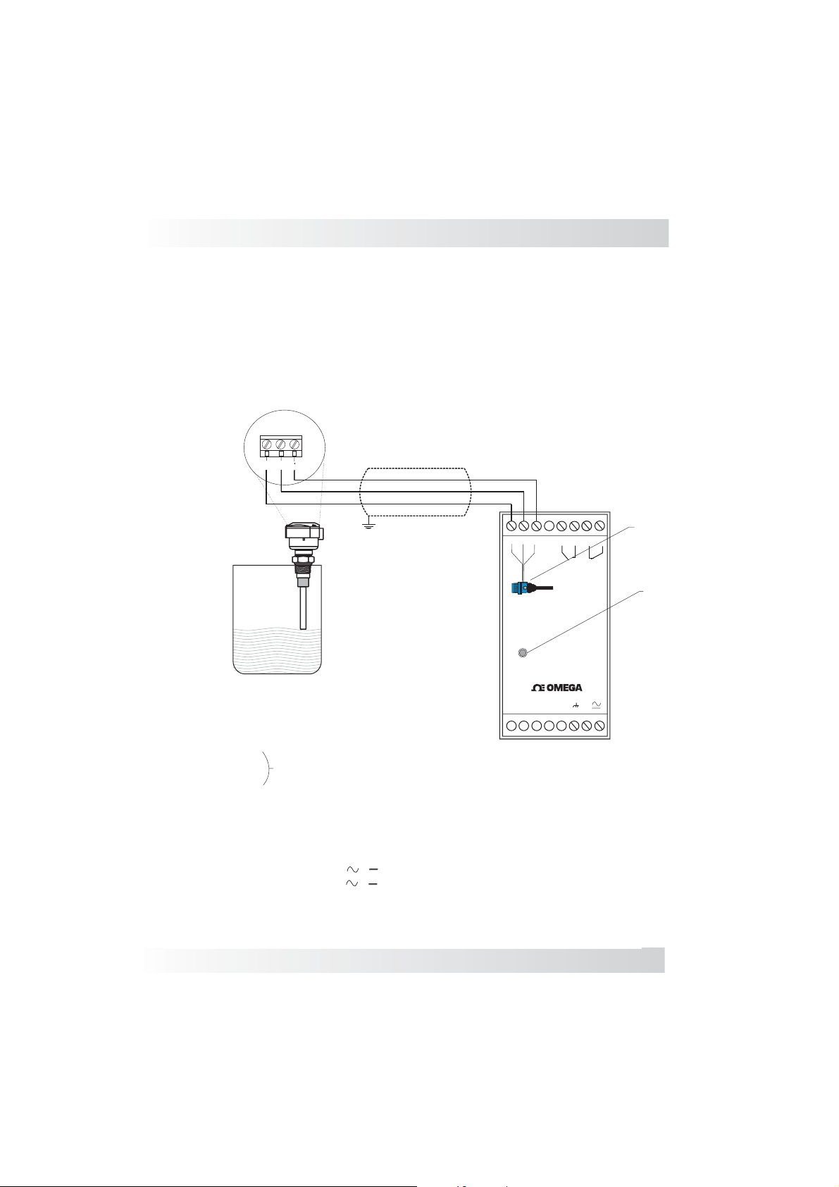
Wiring Diagram
ControllerLVCN400 Series Relay
Note: The LVCN4300 series works in conjuction with the
LVCN400 Relay controller and will not work without it.
& LVCN401LVCN4300 Probe Controller
2
1
3
_
out
+
1-
Out ( Probe Power supply)
235- Contact NO
6- Common
7- Common
8- Contact NC
14- Ground
15- Power Supply ( )( )
16- Power Supply ( )( )
L2- LED: Level Indication
L3- LED: Power
Shielded
1
+
Power
234
_
S
5678
(L2)
5 a 250 V AC
(L3)
LVCN401
®
1591113141210 16
www.omega.com e-mail: [email protected]
07
Page 8
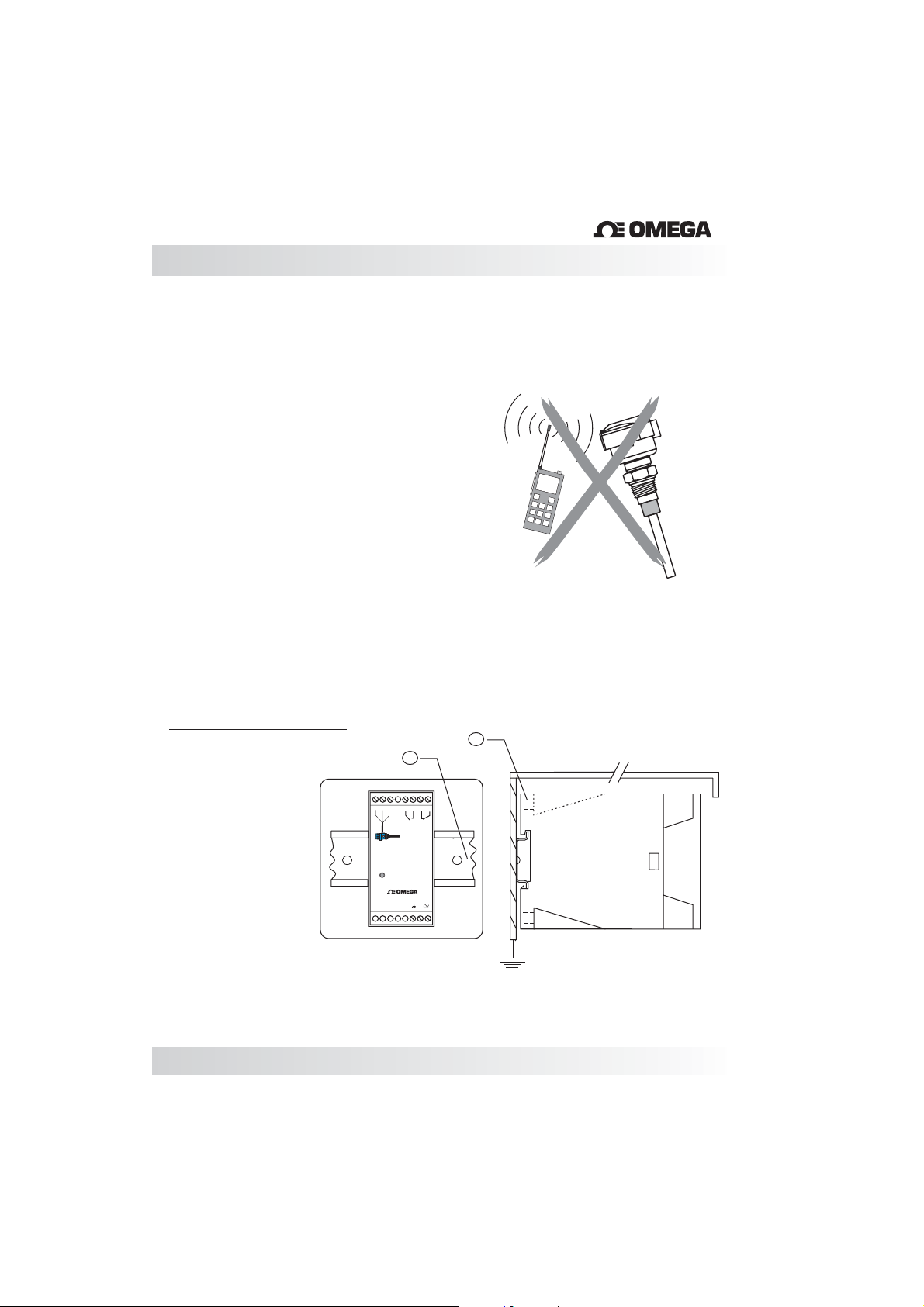
Installation
When making connections between the controller
and the probe use reliability cables and make sure
they are grounded.
Shielded cables prevent interference to the
eletronic signal and protect against false
measurements.
To avoid radio frquency interference and possible
malfunction, keep hand held communication
equipment away from the LVCN4300 and
LVCN400 Series. If this unavoidable make a metal
shield around the the level switch and confirm that
the unit hasbeen properly grounded.
Do not install the controller in harsh environments
and humid. Respect class protection, working
temperature and protect the same from rain and
excessive heat.
Also confirm that a stable Power Supply is used to
prevent equipment malfunction.
®
Controller Mounting
Panel mounting with
the protection cover
A- DIN trail (35mm)
B- Screws
08
1
234567
_
S
+
Power
A
5a 250 V AC
LVCN401
B
Cover
8
®
1591113141210 16
Side view
Grounding
Page 9
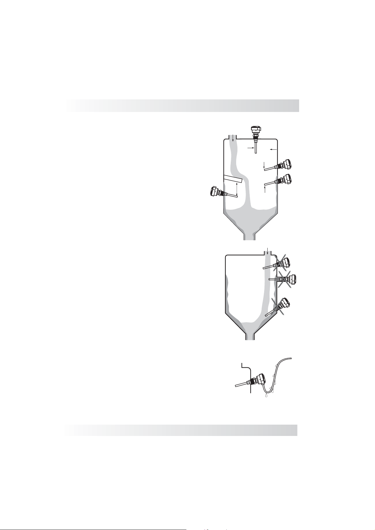
Installation
Verify that the location the probe is to be mounted
is not directly in the path of the product as it enters
the vessel. (Fig.1)
When installing more than one probe, verify that
they are separated by a minimum distance of
500mm. (Fig. 1)
Material falling ontothe probe can causedamage
or switching errors. If this is unavoidable, it is
recommended that a protective shield be installed
above the probe.The shield is also recommended
when the probe is use for a low level switch or in
the outflow ofthe product. (Fig. 2)
The tip of the probe should point slightly
downward ( when possible) so that if there is any
excess of product it will easily slide from the
probe. (Fig. 2)
When installing from the top of the tank confirm
that the tip of the probe has cleared the side of the
vessel at least500mm. (Fig. 3)
Fig. 2
Fig. 3
Shield
Fig. 4
500mm
500mm
Fig. 1
500mm
When installing the sensor directly to the tank
make sure that the rod extends beyond the inner
wall of the tank, by as much as possible, so that
internal build up or other debris does not interfere
with the sensor's performance. (Fig. 2 correct Fig.
4 incorrect)
Ensure that theconduit is facing downward so that
water does not enter the housing from the cable
entry point. (Fig.5)
www.omega.com e-mail: [email protected]
Fig. 5
09
Page 10
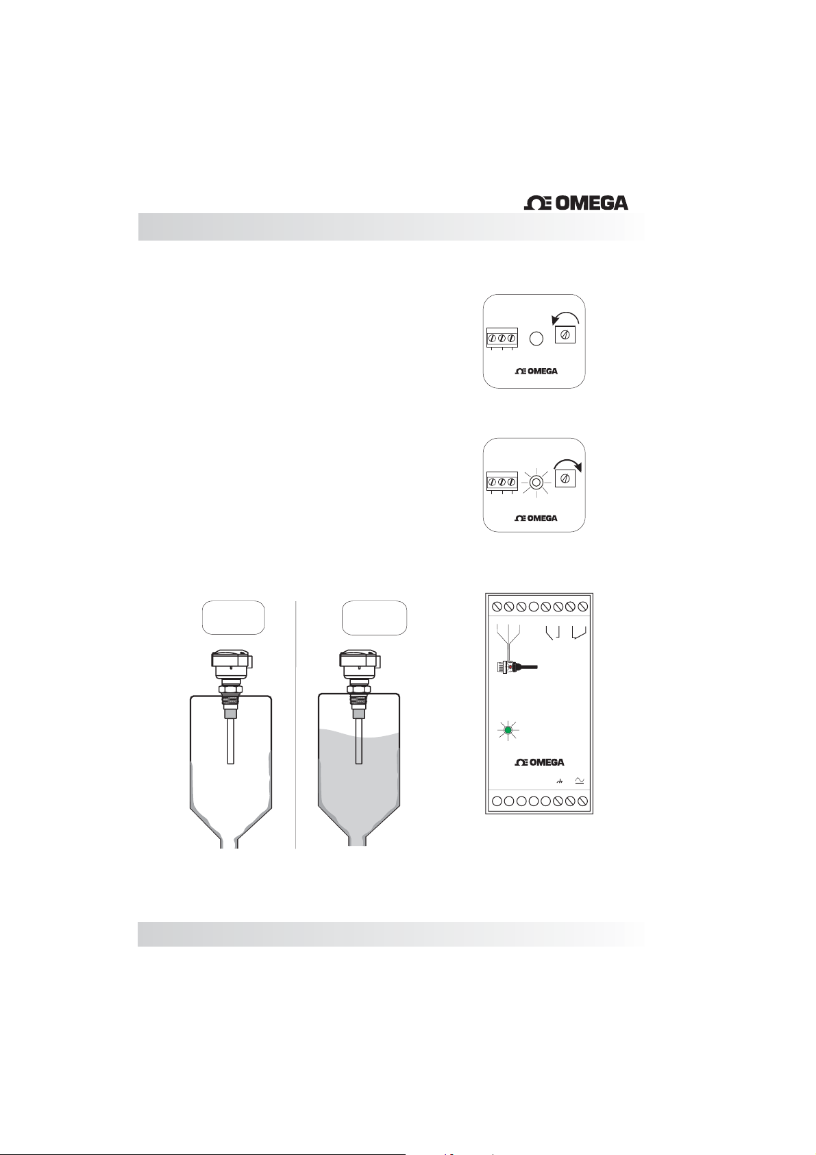
Calibration
Calibration
1. Install the probe and power it on. The green
LED (L3) onthe controller should beon.
2.Turn the potentiometer (P1) counter-clockwise
(Fig.1) before the tank is filled.
4.Fill the tank until the probe is in contact with the
medium.
5. Turn the potentiometer clockwise until the LED
(L1) of the probe and the LED (L2) on the
controller are on.(Fig.2)
Products with a low dielectric constant may
require most orall of theactive length of the probe
to be covered by the product before the controller
activates the relay.
red
Fig.1
Fig.2
LVCN4300
3
2
1
_
out
+
LVCN4300
3
2
1
_
out
+
®
Sens.
L1
®
Sens.
L1
®
10
Probe: (L1)- off
Controller: (L2)- off
(L3)- on
Probe: (L1)- on
Controller: (L2)- on
(L3)- on
1
+
234
_
Power
S
L2
L3
5678
5A - 250 V AC
LVCN401
®
1591113141210 16
Page 11
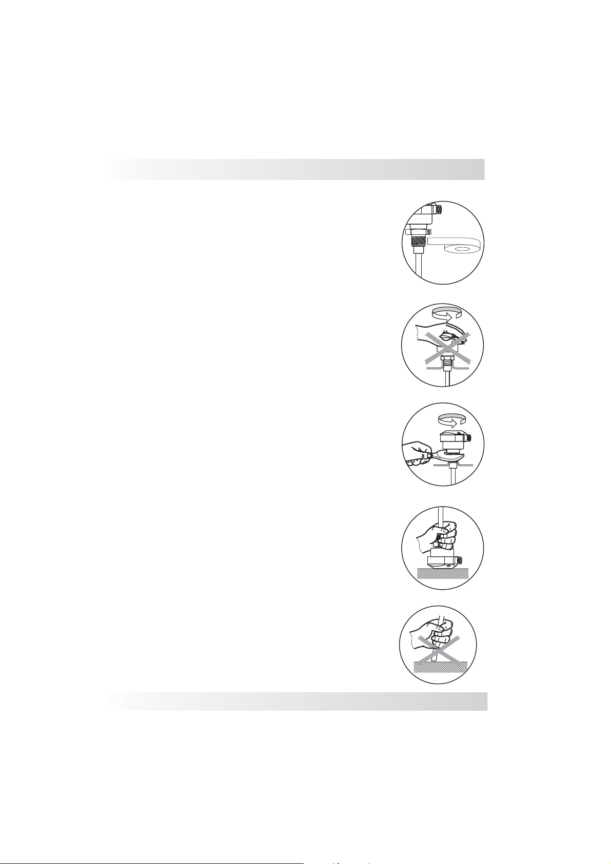
Handling
Probes:
Seal the thread with Teflon tape before
installation. (Fig. 1)
Do not turn or handle by the housing. (Fig. 2)
When tightening the sensor, use only use the
316S.S. hexagon fitting to achieve a seal, do not
twist with thebody of the sensor. (Fig. 3)
The probe should not be dropped or suffer any
impact or fall that could damage the electronics or
the coating ofthe probe. (Fig. 4and 5)
Periodic visual inspection of the probe is required
to check for corrosion or deposit build-up. If
deposits are found, clean the sensor to ensure
optimum performance.
Fig. 1
Fig. 2
Fig. 3
Fig. 4
Care should be taken when handling and installing
probes with coated rods to avoid scratching them.
Scratching the coating could interfere with the
probe performance.
When cleaning therod use a softbrush or rag.
www.omega.com e-mail: [email protected]
Fig. 5
11
Page 12
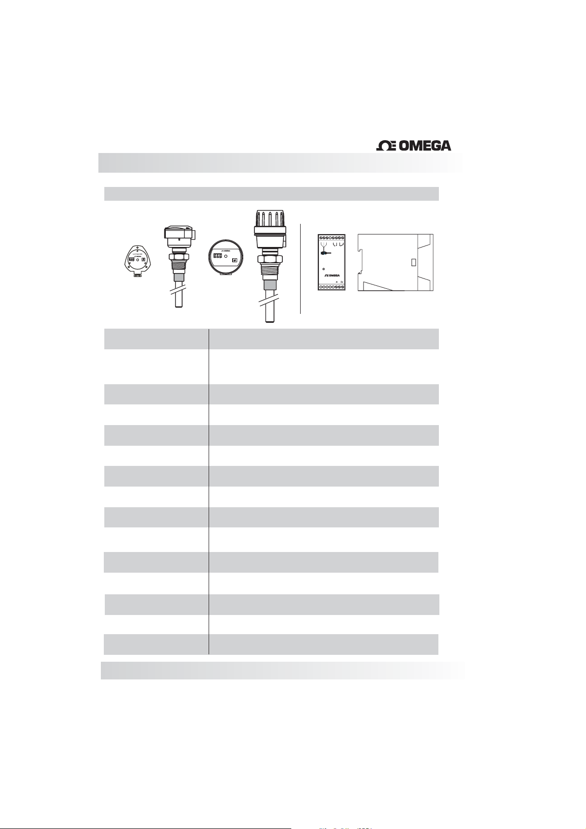
Technical Specification
LVCN4300 + LVCN400 Series
®
2
3
LVCN4300
®
3
2
1
_
out
Sens.
+
Nylon housing
1
LVCN4300
_
out
on
+
Sens.
Aluminum housing
1
8
234567
_
S
+
5a 250 V AC
LVCN401
Power
®
1591113141210 16
LVCN400 - Controller
®
Application
Power Supply
Consumption
Adjustment
Sensitivity
Level Indication
Output
Electrical Connection
Process Connection
Wetted Parts
Enclosure Material
Housing
Max. Pressure
Level Detection for Solids and liquids.
LVCN401: 24Vdc (+/- 10%)
LVCN402: 110Vac (50/60Hz)
LVCN403: 220Vac (50/60Hz)
2VA
Sensibility
0to5pF
LED ON/OFF
Relay (SPDT) 5A-250Vac
Cable Gland - 1/2” NPT or M12 connector
3/4” to 1 1/2” BSP or NPT Flange or Sanitary
316SS, ETFE or ECTFE Coated
Relay : ABS ( Resistant thermoplastic)
Nylon Fiberglass (Optional Aluminum)
290 PSI (20 Bar)
Operating Temperature
Class Protection
12
Probe: (-10 to 120ºC) / Controller -10 to 60°C
Probe: IP 65 / Controller: IP40
Page 13

Trouble Shooting
Fail
Relay does not
work
Relay does not
turn off
Cause
LED off,
without Power Supply
Lack of signal from
LVCN400
Low sensitivity
Coating on the rod
is damaged
Material Build-up on the rod
Solution
Check the Power Supply
Verify the connections
Adjust sensitivity with
the potentiometer
Consult for repair or
replacement
Clear the rod
www.omega.com e-mail: [email protected]
13
Page 14
Page 15

M-3995/0912
 Loading...