

Page 1
®
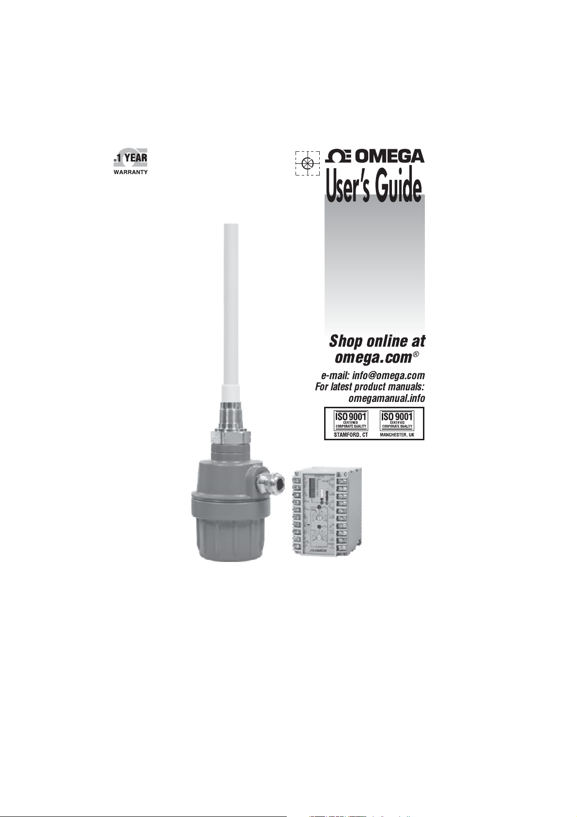
LV3000 and LVCN410 Series
Continuous Level Measurement
Page 2

®
Page 3

Contents
Introduction .................................................4
Models & Dimensions .........................................5
Wiring Diagram
Mounting Note
Installation .................................................11
Calibration .................................................15
Handling ..................................................18
Technical Specifications ......................................19
Trouble Shooting
..............................................7
...............................................9
............................................21
www.omega.com e-mail: [email protected]
03
Page 4
Introduction
LV3000 and LVCN410 Series
Continuous Level
Measurement
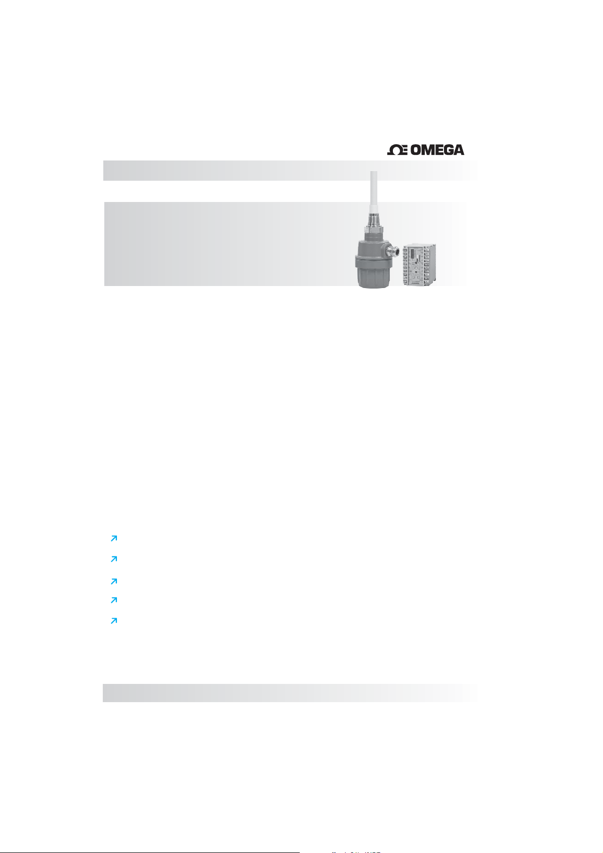
The LV3000 Series Capacitance Level Measurement System is designed to
measure and control the level in most industrial applications. The probe
works in conjunctionwith the Series of levelcontrollers. The is
available in 316SS with optional ETFE tubing or ECTFE coatings (required for
conductive or aggressive mediums). The LVCN410 controller with an integrated
bar graph display gives the operator an overview of the level within the vessel.
With 4...20mA output signal and up to 2 Relay switch outputs, this system
provides a complete level control solution for mostapplications.
How it works:
A capacitor consists of the probe’s rod as one plate and the metallic wall of the
vessel (or a secondary reference rod or sheath) as the other plate. As the
medium rises and displaces the empty space within the vessel, the dielectric
constant around the probe changes. This change is recorded andconverted into
either a relay switch output or a 4…20mA output signal which is proportional to
the level withinthe vessel. By using this principle, the + Series
can be applied in a wide range of products such as most liquids, powders,
pastes and granular mediums.
LVCN410 LV3000
LV3000 LVCN410
LV3000
®
Features
Used in a wide range of application/industries
Accurate and reliable measurement.
No moving parts - Rugged construction.
Can operate at hight temperatures and pressure.
Functions on conductive as well as non-conductive medias.
04
Page 5
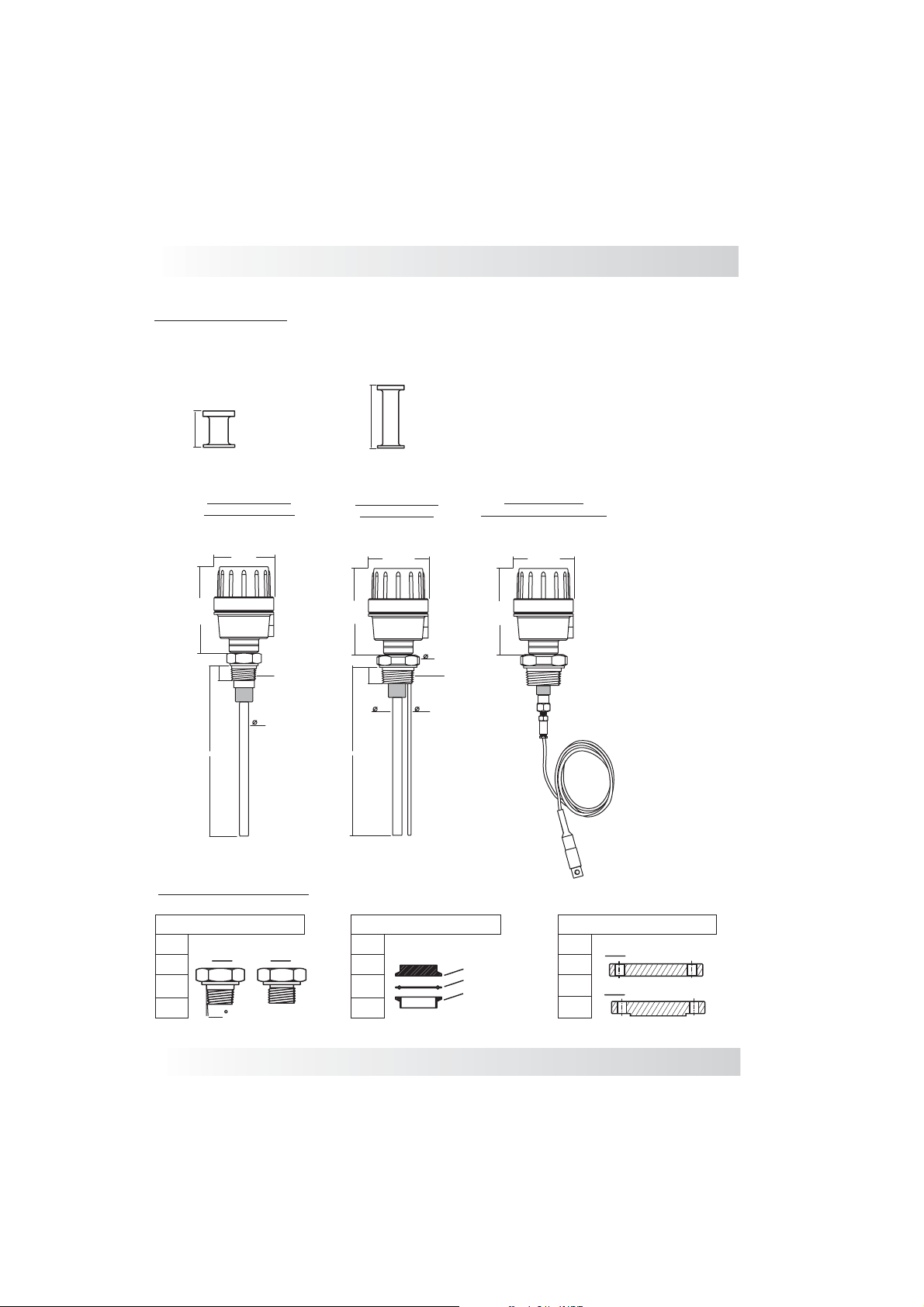
Mounting Options
Extended Necks for Higher Temperatures
Models & Dimensions
50mm
100mm
Note: Medium T (up to 120°C) and High Temperature (up to 150°C)emperature
LV3000 Standard
Aluminum Housing
89mm
126mm
1”NPT
½”
L
LV3000 Standard
Reference Rod
89mm
126mm
25
L
1 1/2”NPT
½”
1/4”
(also w/ Reference Cable)
66
Obs: Minimum Insertion Length for the LV3000 is 1/2 meter
Process Connection
LV3000 w/ cable
89mm
126mm
Tri-Clamp Flange
1½”
2”
2½”
3”
3/4”
1”
1½”
2”
Threaded
NPT
1,75
BSP
www.omega.com e-mail: [email protected]
TC Connection
Rubber Seal
Process Connection
1”
1½”
2”
2½”
FF
RF
ANSI 150#
ANSI 300#
05
Page 6
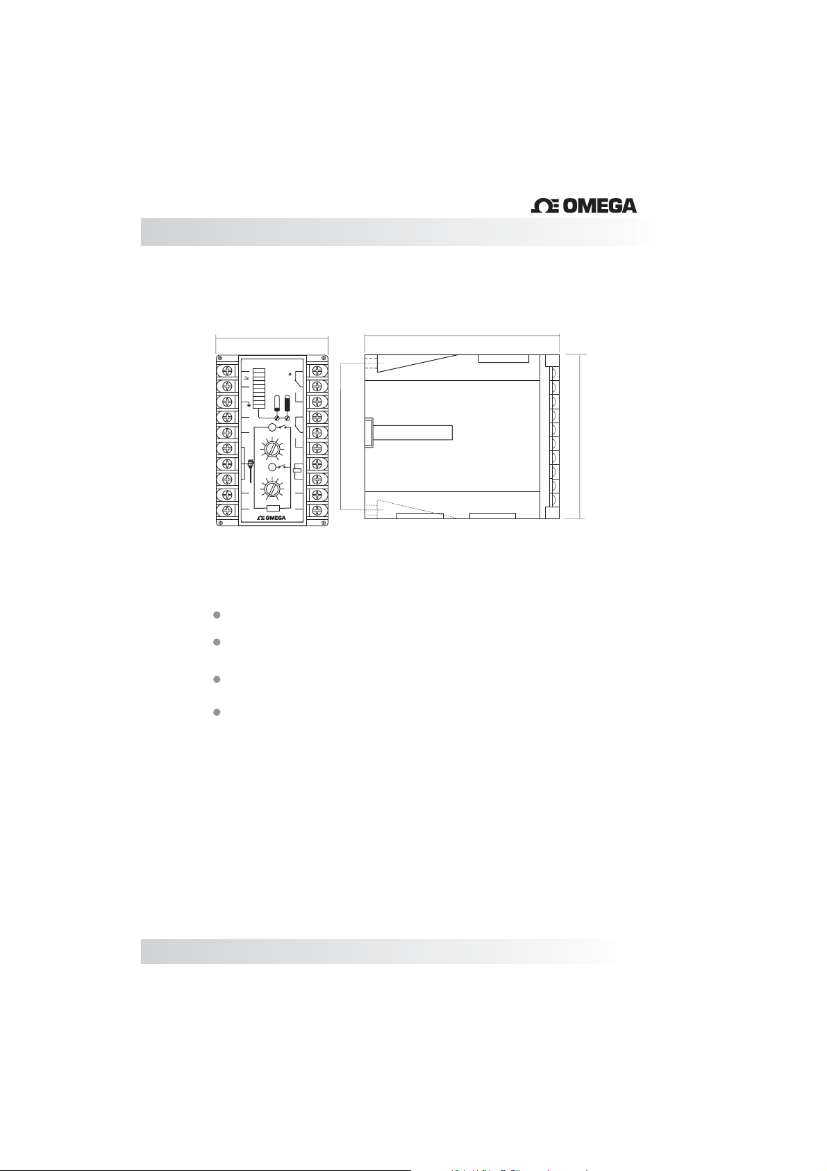
Models & Dimensions
LVCN410
®
75mm
LVCN410
1
2
3
4
5
High
6
S
7
+
Low
8
_
9
out
0/5Vcc
10
100%
90
80
70
60
C N 200
50
40
30
20
10
5
4
3
2 8
1
0
5
4
3
2 8
1
0
LIMIT
20
Power
19
18
17
16
6
7
15
9
10
14
+
Test
_
6
13
7
12
+
9
out
10
4/20mA.
_
11
®
99mm
Features
Bargraph Level Indicator from 0 to 100%
Output 4...20mA or (0...5 Vdc optional)
with Zero and Span adjustment
2 Outputs Relay (Low and High) with with
individual set-point Adjustment
P vailable in 24Vdc
ower Supply a (LVCN411)
or 85...265Vac
(LVCN412)
109mm
110mm
06
Page 7
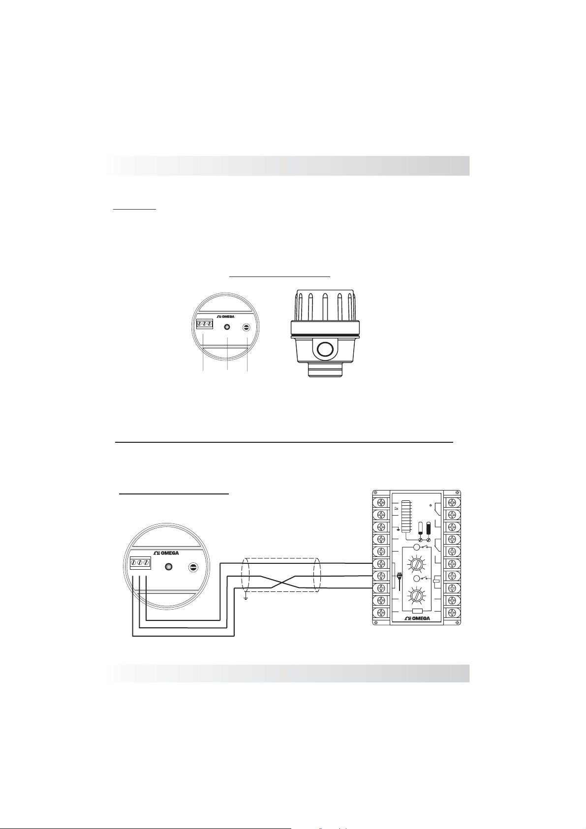
Wiring Diagram
LV3000:
The LV3000 Series works in conjunction with theLVCN410 Controller.
Do not powerthe probe with another brandof controller.
ALUMINUM HOUSING
LV3000
®
II
I
-
+
S
L1- LED Status: Connected
S1- Sensitivity Control
P1- Power Supply and Output Signal.
III
On
Sens.
(L1) (S1)(P1)
Important: Before connecting the equipmente, make sure it is properly
powered as show on ID tag.
LV3000 & LVCN410
+
1
Aluminum Housing
LV3000
®
II
I
-
+
S
On
III
Sens.
13Vdc
S
-
+
Max. 300 meters
Shield
www.omega.com e-mail: [email protected]
S
+
-
2
3
4
5
6
6
S
7
7
+
8
8
_
9
out
0/5Vcc
10
LVCN410
-
High
3
2 8
1
Low
3
2 8
1
20
100
%
Power
90
80
19
70
60
50
LVCN410
40
30
18
20
10
17
16
5
4
6
7
15
9
0
10
14
+
Test
5
_
6
13
4
7
12
+
9
out
10
0
4/20mA.
_
11
LIMIT
®
07
Page 8
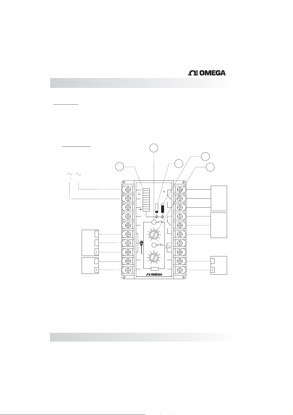
Wiring Diagram
LVCN410
A- Bargraph Level Indication.
B- LED Set-point Indication (Low & High).
C- Adjust Zero ( low level).
D
- Adjust Span (high level)
E- Adjust Set-point.
®
Power Supply
DC: 24Vdc +- 10% (LVCN411)
AC: 85...265Vac (LVCN412)
A
()
(+)
6
S
Output
Probe
(Optional)
Output
0..5v
7
+
8
9
+
10
1
2
3
4
5
6
7
8
9
0/5Vcc
10
+
_
S
+
_
out
B
LVCN410
100%
Power
90
80
70
60
50
LVCN410
40
30
20
10
High
5
4
6
3
2 8
1
0
5
Low
6
4
3
2 8
1
10
0
LIMIT
D
C
20
19
18
17
16
7
15
9
10
14
+
Test
_
13
7
12
+
9
out
4/20mA.
_
11
®
E
18 19 20
17
15 16
12
11
NC
C
NO
NC
NO C
+
Output
Relay Hight
Output
Relay Low
Output
4...20mA
8
Page 9
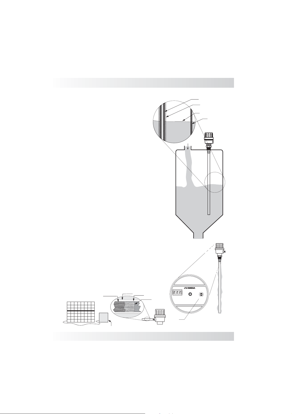
Mounting Notes
Mediums that are conductive will cause a short
circuit between a bare stainless steel probe and
the tank wall. For that reason we recommend
the use of ECTFE or other types of insulating
coatings on the rod's surface. (Fig. 1)
Material build-up also affects the accuracy of
RF capacitive measurements, and therefore
additional adjustment to the probe's sensitivity
is recommended in applications where build-up
is a concern. (Fig. 2)
Housings must also be compatible with the
requirements for wash-down, wet, and/or dusty
environments. Hazardous environments may
require the housing to be certified. In addition,
the active probe might need to be intrinsically
safe or have an intrinsic safety barrier. (Fig. 3)
The electronic circuitry of the probe performs
several functions such as rectifying and filtering
the incoming power, generating the radio
frequency signal, measuring the changes in
current flow, analog signal generators and
display meters. The circuitry is provided with
potentiometer adjustments for setting
sensitivity that is located in the housing of the
probe. These adjustments give an added level
of fine-tuning which enable the user to control
the probe's sensitivity with greater accuracy.
(Fig. 3)
Fig. 1
Bare Rod
Coating
(ETFE or )ECTFE
Conductive Medium
Steel Tank
Fig. 2
Variation in current input (power supply) to the
probe will affect the output. Therefore, a stable
power supply should be available.
Fig. 4
Wire Shield
Power Supply
(Fig. 4)
Conduit
Cable
www.omega.com e-mail: [email protected]
Wires
Conduit
Fig. 3
-
+
S
Sensibility
LV3000
On
®
II
I
III
Sens.
09
Page 10
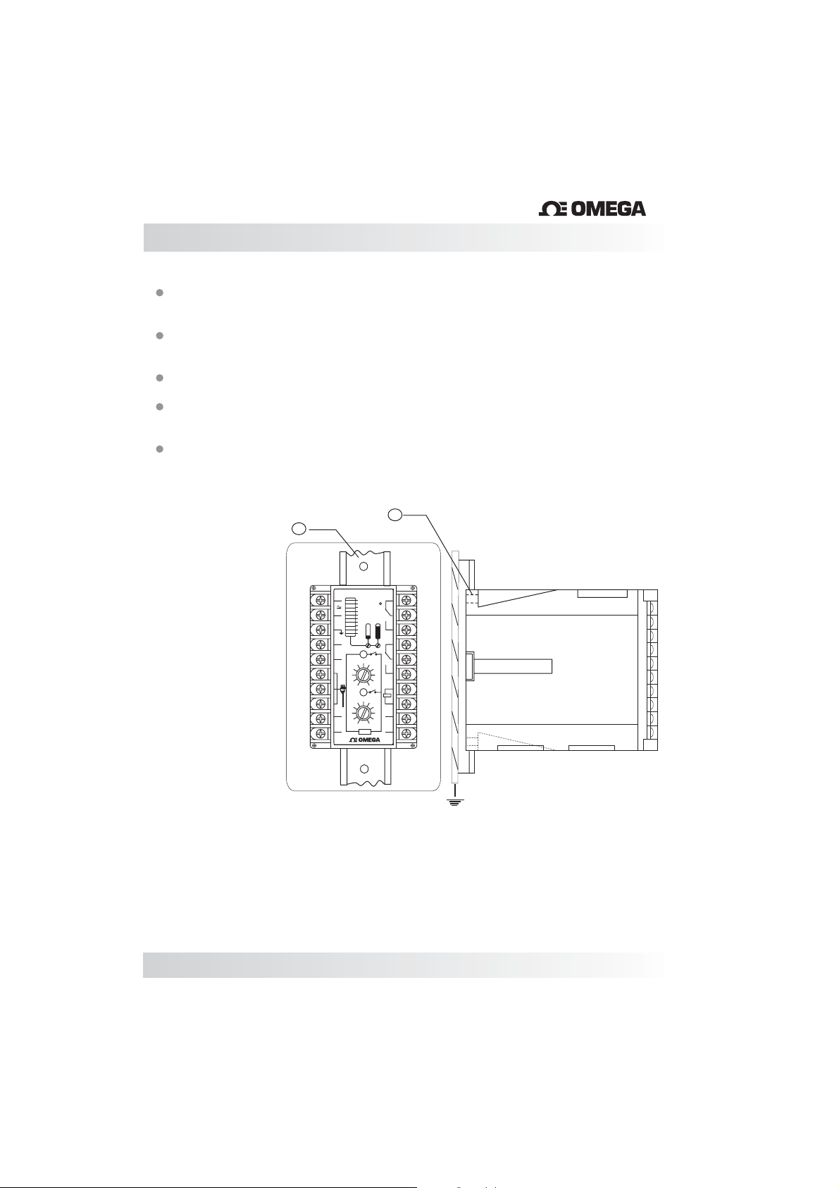
Mounting Notes
When making connections between the controller and the probe use
reliable cables and make sure they are grounded.
Shielded cables prevent interference improving and protecting against
false measurements.
Do not install the controller in harsh environmentsand humidity.
Respect class protection, working temperature and protect the same
from rain and excessive heat.
A stable power supplyprevents damage and equipment malfunction.
®
Panel mounting with
the protection cover
C- DIN trail (35mm)
D- Screws (3,5mm)
Note: LVCN410 can be
installed vertically or
horizontally.
C
D
LVCN410
+
1
2
-
3
4
5
6
S
7
+
8
_
9
out
0/5Vcc
10
100
90
80
70
60
50
40
30
20
10
High
5
4
3
2 8
1
0
5
Low
4
3
2 8
1
0
LIMIT
%
LVCN410
20
Power
19
18
17
16
6
7
15
9
10
14
+
Test
_
6
13
7
12
+
9
out
10
4/20mA.
_
11
®
Side View
Ground
10
Page 11
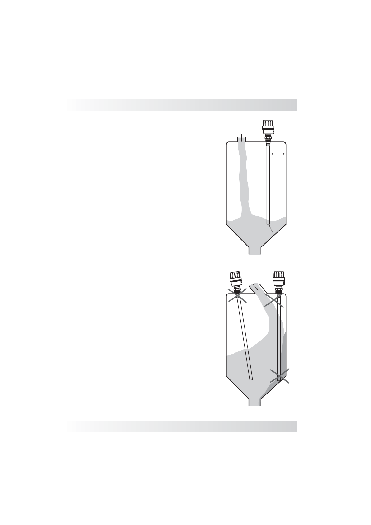
Installation
When installing the probe either directly to the
tank, or utilizing a connection, the capacitance
probe should be mounted on the top of the tank,
never on the side or angle, so that the rod stays
parallel to the tank wall.
(Fig. 1 correct Fig. 2 Incorrect)
The mounting location of the probe should stay
clear away from the point where the medium
enters, this will avoid false reading from the sensor
while being filled.
(Fig. 1 correct Fig. 2 Incorrect)
The recommended distance of installation of the
probe from the internal wall is a minimum of
500mm, and from the tip of the rod to the bottom of
the tank is 100mm, this will prevent a false signal
and possible build up between the wall and probe.
(Fig. 1 correct Fig. 2 Incorrect)
For high pressure and explosion proof
Note:
applications, care should be taken when tightening
the connection as achieving a proper seal is very
important.
Fig. 1
500mm
100mm
Fig. 2
www.omega.com e-mail: [email protected]
11
Page 12
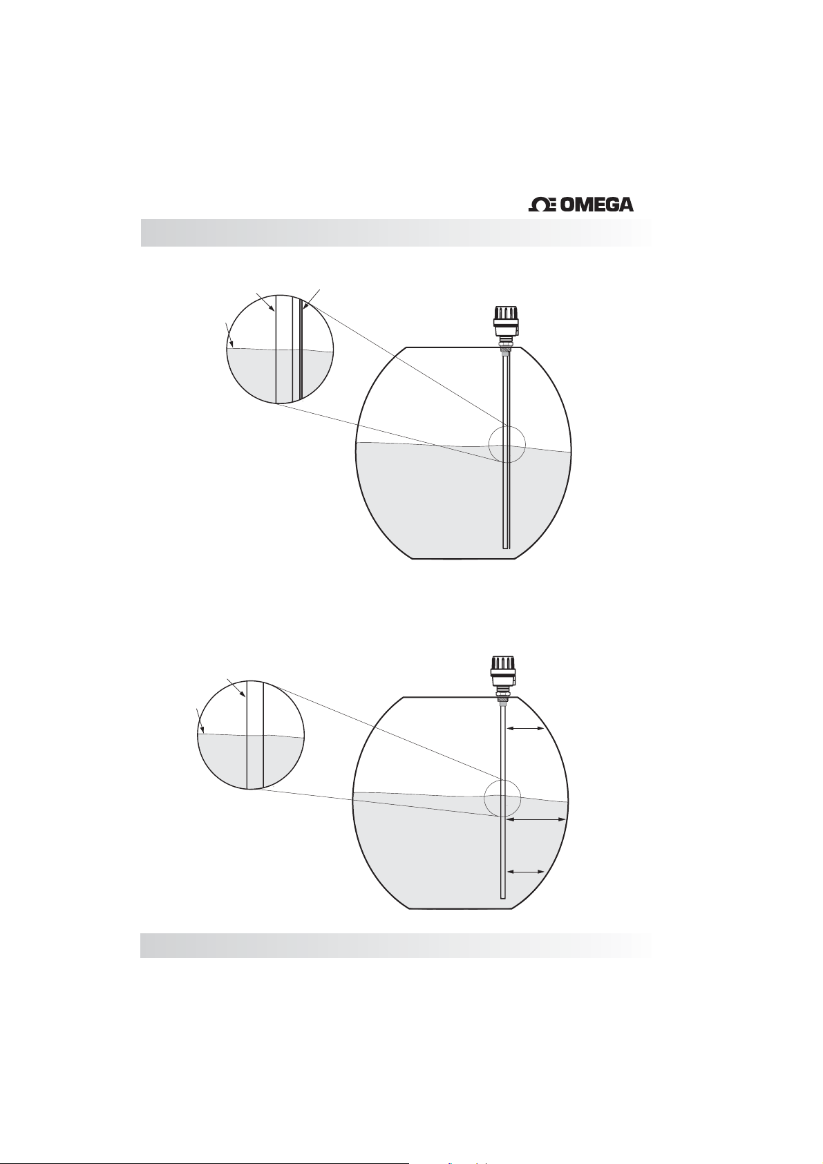
Installation
®
Rod
Level
Referrence Rod
In order to achieve a linear output
signal, the main rod of the probe
must have a parallel reference
either to the tank or to a
secondary reference rod or
sheath. If the probe is mounted
without this parallel reference
within a cylindrical tank that is
mounted on its side, the output
signal will not be linear. Please
consult one of our application
engineers if you have further
questions.
(Correct/Fig.2 incorrect)
Single Rod
Fig. 1
Fig. 2
12
Level
L=y
L=z
L=x
Page 13
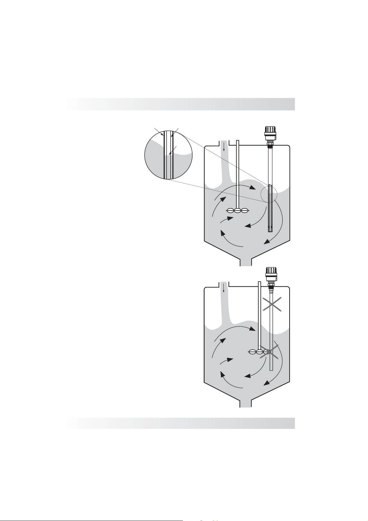
Installation
Sheath
The tank must be free from turbulence or
vortices throughout use. If this is not
possible we highly recommend a stilling
well or sheath.
(Fig. 1 correct, Fig. 2 incorrect)
Ensure that mounting position does not
interfere with any obstructions wthin the
vessel or tank.
(Fig. 1 correct, Fig. 2 incorrect)
Rod
Fig. 1
Level
Fig. 2
www.omega.com e-mail: [email protected]
13
Page 14
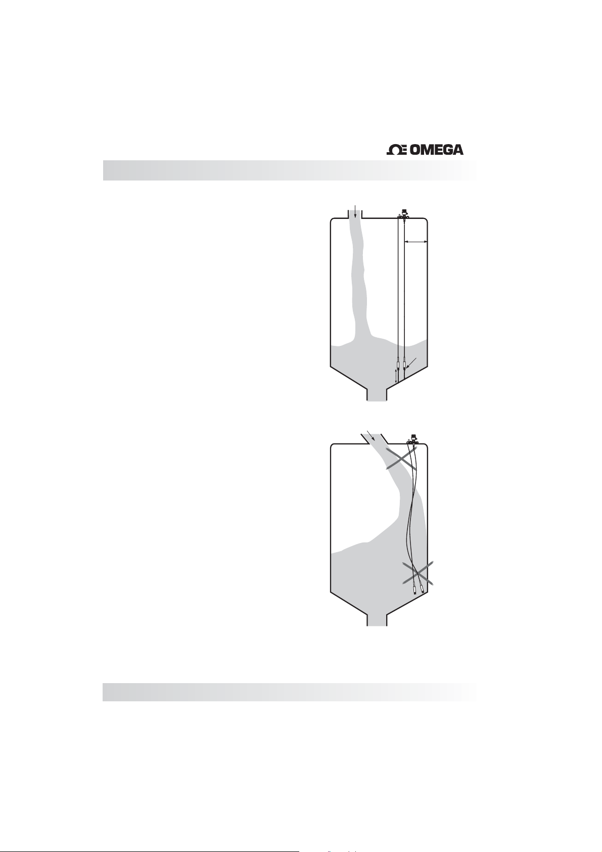
Installation
®
When installing the LV3000 with cable and
reference be sure that they are well connected
to the bottomof the tank and that it hasno slack.
(Fig. 1 correct Fig. 2 Incorrect)
The mounting location of the probe should stay
clear away from the point where the medium
enters, this will avoid false reading from the
sensor while being filled.
(Fig. 1 correct Fig. 2 Incorrect)
The recommended distance of installation of
the probe from the internal wall is a minimum of
500mm, and from the tip of the pendulum to the
bottom of the tank is 100mm, this will prevent a
false signal and possible build up between the
wall and probe.
(Fig. 1 correct Fig. 2 Incorrect)
If the cable is secure to the bottom of the vessel
it must be isolated and the vessel is steel it must
be isolated so that it does not create a short
circuit.
Fig. 1
500mm
Isolator
100mm
Fig. 2
14
Page 15
LVCN Controller Calibration
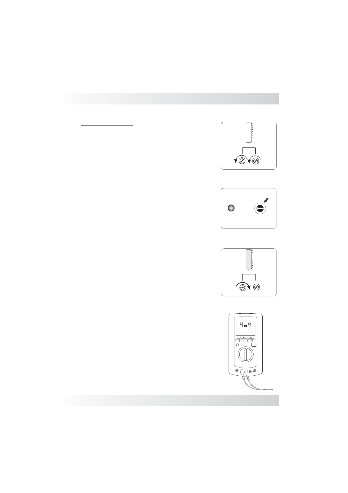
Adjustment 4mA
It is recommended that an multimeter be connected
according to the figure(fig.4) to monitor the current
value during the calibration. Prior to calibration it is
recommended that both potentiometers are reset.
Turn both potentiometers counter-clockwise or
approximately 5 turns. (Fig. 1)
The bargraph is calibrate according to the signal
(4mA-0% and 20mA- 100%).
1) Drain the tank to minimum level (Zero%or 4mA).
2) Select the Sens. switch 1,2,3 located in the probe
Unit LV3000. It is recommended to begin with Sens.
switch 1. (Fig. 2)
3) Use the Zero potentiometer to set the current
value for the actual level to 4mA or 0%. Turn the
potentiometer clockwise to increase current. Turn
the potentiometer counter-clockwise to decrease
current. If you are unable to set the probe at 4mA,
alter the Sensitivity potentiometer (Fig.2) position
and try to adjust the minimum value (4mA) through
the Zero Potentiometer again. (Fig.3)
Fig.1
Fig.2
Fig.3
On
100
Zero
Span
LV3000
I
Sens.
100
Span
Zero
%
90
80
70
60
50
40
30
20
10
II
III
%
90
80
70
60
50
40
30
20
10
www.omega.com e-mail: [email protected]
Fig.4
15
Page 16
LVCN Controller Calibration
®
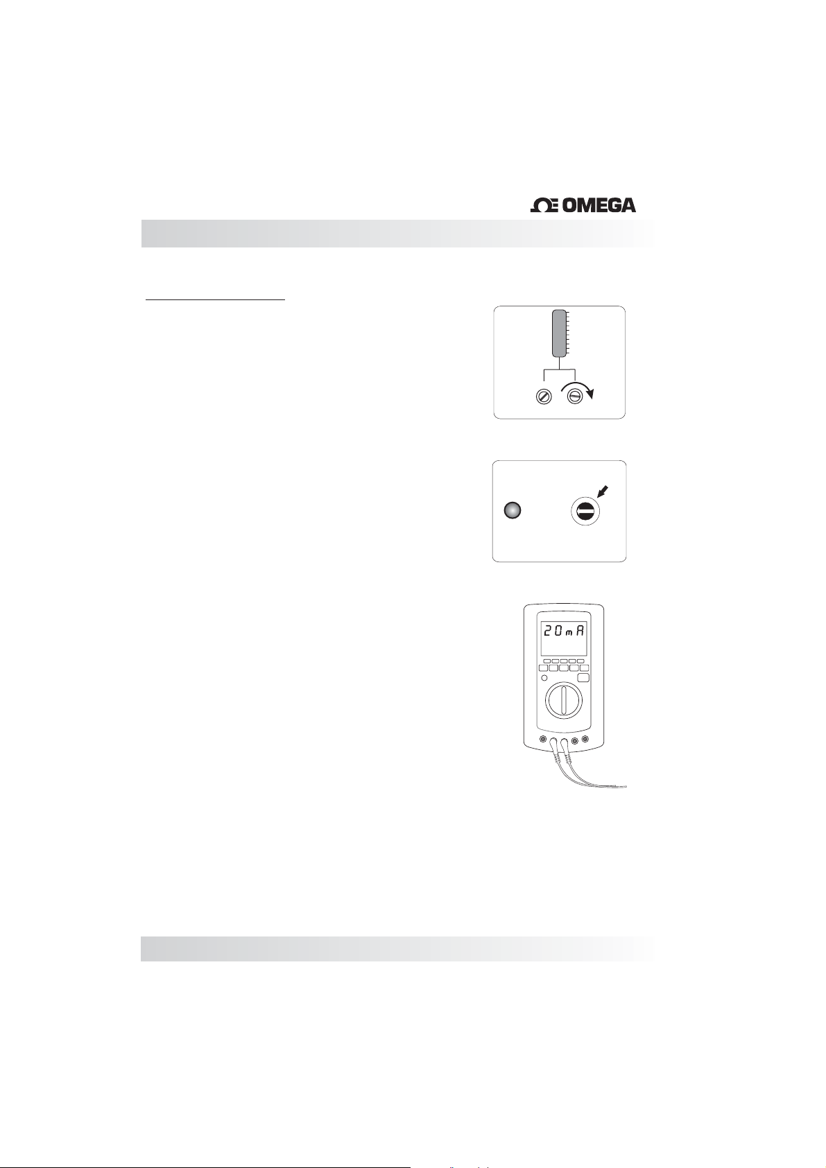
Adjustment 20mA
After calibrating the minimum value (4mA or 0%), fill
up the tank to maximum level (100% -level).
4) Use the Span potentiometer to set the current
value for the actual level to 20mA or 100%. Turn the
potentiometer clockwise to increase current. Turn
the potentiometer counter-clockwise to decrease
current (Fig.5).
5) If the current is lower than 20mA or 100% after fully
turning the Span Potentiometer clockwise, it is
necessary to increase the sensitivity by selecting the
next level of the switch ( Sens.). If the current still
remains lower than 20mAor 100%, continue on to the
next level until achieve 20mA.
6) With the 20mA or 100% signal adjusted itis best to
re-adjust the Zero. Drain the tank back down to the
starting level and re-adjust (if necessary) the
minimum level to 4mA or 0% one more time. After
this stage, set-up is complete.
Fig.5
Fig.4
Full bargraph
On
100
90
80
70
60
50
40
30
20
10
Span
Zero
LV-3000
I
Sens.
%
II
III
16
Page 17
LVCN410 Calibration
LVCN410 Set-Point adjustment
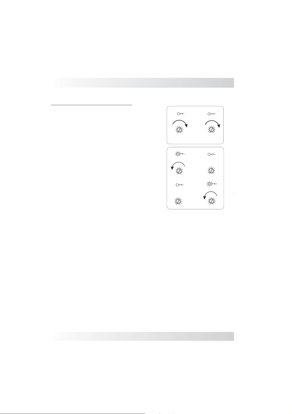
After completed the calibration, it is necessary to be done
to adjust the set-point outputs of the case is used.
LVCN410 controller has 2 outputs Relay (SPDT),with indication
LOW and HIGH. To adjust, make sure the outputs are not
actuated (statement made by the LED’s), if necessary turn
the potentiometers clockwise (fig.1).
1) Low Level Control.
Fill the tank to the first point , then turn the potentiometer
(Low) counter-clockwise until the LED indicator turn-on.
2) High Level Control.
Fill the tank to the second point, then turn the
potentiometer (High) counter-clockwise until the LED
indication turn-on.
With two adjusted points, confirm the points draining and
filling the tank until the set-points, re-adjust if necessary.
Fig.1
1)
2)
Low
Low
Low
3
2 8
1
5
4
3
2 8
1
0
Output Relay
5
4
3
2 8
1
0
5
4
0
High
5
4
6
7
9
10
3
2 8
1
0
6
7
9
10
High
5
4
6
7
9
10
3
2 8
1
0
Output Relay
6
7
9
10
High
5
6
7
9
10
4
3
2 8
1
0
6
7
9
10
www.omega.com e-mail: [email protected]
17
Page 18
Handling
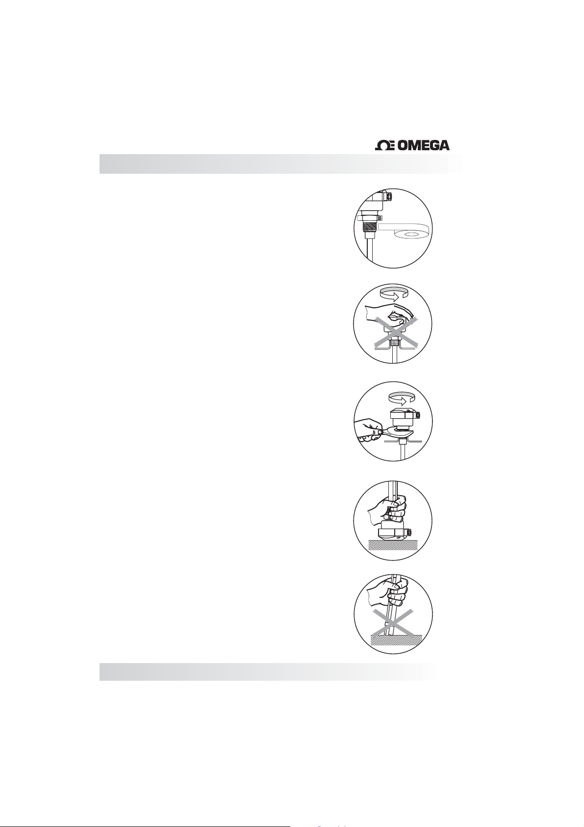
Probes:
Seal the thread with Teflon tape before
installation. (Fig. 1)
®
Fig. 1
Do not turn or handle by the housing. (Fig. 2)
When tightening the sensor, use only use the
316S.S. hexagon fitting to achieve a seal, do not
twist with the body of the sensor. (Fig. 3)
The probe should not be dropped or suffer any
impact or fall that could damage the electronics or
the coating of the probe. (Fig. 4 and5)
Periodic visual inspection of the probe is required
to check for corrosion or deposit build-up. If
deposits are found, clean the sensor to ensure
optimum performance.
Care should be taken when handlingand installing
probes with coated rods to avoid scratching them.
Scratching the coating could interfere with the
probe performance.
Fig. 2
Fig. 3
Fig. 4
When cleaning the rod use a soft brush or any
other similar object.
18
Fig. 5
Page 19
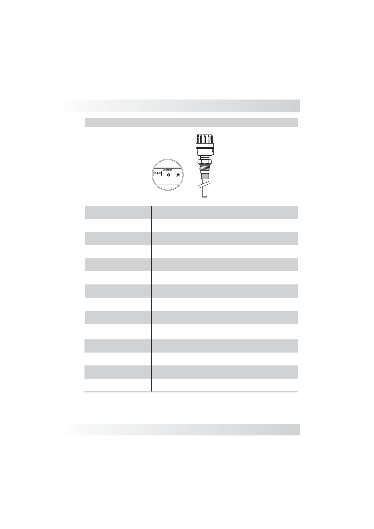
LV3000 Aluminum Housing
Aluminum Housing
LV3000
®
II
I
-
+
S
III
On
Sens.
Technical Specification
Application
Current Consumption
Adjustment
Sensitivity Range
Frequency Oscillation
Accuracy
Repeatability
Electrical Connection
Process Connection
Wetted Parts
Enclosure Material
Max Pressure
Operating Temperature
Class Protection
Continuous Level Measurement for Liquids and Solids
22mA max
Sensibility. (1,2,3 stages)
100 to 5500pF
400 kHz
0.5%
+/- 1mm
½” NPT, M12 Conector or Cable Gland
3/4” to 1 1/2” BSP or NPT Flange or Sanitary Connections
316 Stainless Steel, ETFE, ECTFE
Aluminum
290 PSI (20 Bar)
-10 to 80ºC
(IP 65)
www.omega.com e-mail: [email protected]
05
19
Page 20
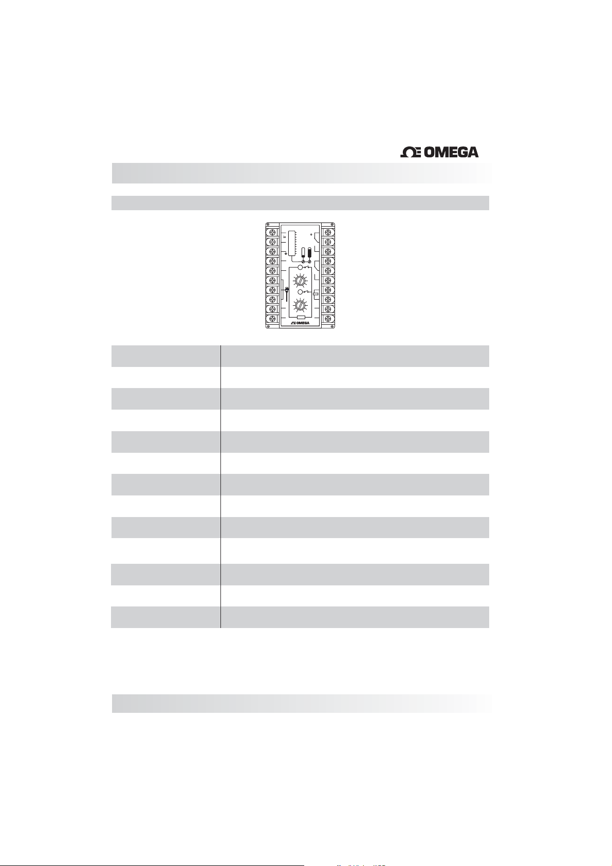
Technical Especifications
Controller LVCN410
LVCN410
+
1
100
90
80
70
2
-
60
50
40
30
3
20
10
4
5
High
5
4
3
6
S
2 8
1
0
7
+
5
Low
8
_
4
3
2 8
9
1
out
0
0/5Vcc
10
LIMIT
®
20
%
Power
19
C N 200
18
17
16
6
7
15
9
10
14
+
Test
_
6
13
7
12
+
9
out
10
4/20mA.
_
11
®
Application
Operating Voltage
Current Consumption
Adjustment
Output
Accuracy
Repeatability
Level Indication
Dimensions
Enclosure Material
Fixation
Operating Temperature
Class Protection
Continuous Level Measurement for Liquids and Solids
24Vdc (10%) (LVCN411)
85...264 Vac (50/60Hz) (LVCN412)
22mA max
Zero & Span and 2 Set-Point Control
4...20mA & 2 Relay Output (SPDT 5A-250Vac)
0.5%
+/- 1mm
Bargraph
x xxx
L W H ( 109mm 75mm 110mm )
ABS ( Thermoplastic Resistant )
2 screws & DIN Trail(35mm)
32 to 140º F (0 to 60ºC)
(IP 64)
20
Page 21
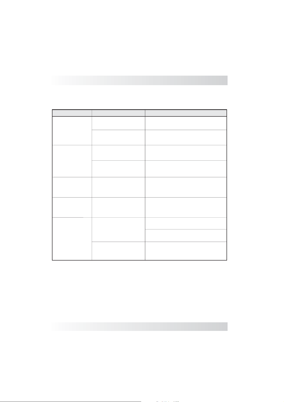
Trouble Shooting
Fault
No signal
Signal over
22mA
Signal Fluctuating
Signal under
20mA
Lack of linearity
Cause Solution
No power supply
Inadequate connection
Probable short circuit
Sensitivity to high
Lack of signal from
referance rod
Sensitivity to low
Reference is incorrect
Coating on the rod
is damaged
Verify power supply
Verify the polarity of the power supply
Verify that the rod is coated for
conductive mediums
Adjust sensibility again
Verify the grounding
Adjust sensibility again
Add a Reference
Sheath the rod
Send back for repair
www.omega.com e-mail: [email protected]
21
Page 22
Page 23

M-3996/0912
 Loading...