

Page 1

1
Page 2

2
Page 3

INTRODUCTION/TABLEOFCONTENTS StepOne
The general purpose indicator displays tank level or volume in engineering units with 1‐4 relay status
indicators, and is compatible with any LVCN‐414, LVCN‐210 & LVCN‐318 Series level sensor that's been
configured with LVCN‐414‐SW 6.0 software and updated to V50 firmware or higher. Powered by the LVCN‐
414,LVCN‐210&LVCN‐318Seriessensor,thefield mountindicatormaybelocatedupto4.5m (15')fromthe
sensor.LVCN‐40Seriesrequiresno programming.The indicatorrepeatsthe measuredvalue,applicablerelay
status and set point configuration of the attached sensor. If the level
changing,theycanbeeasilymadethroughthefieldindicator.
TableofContents
Specifications:.........................................................................................................................................................4
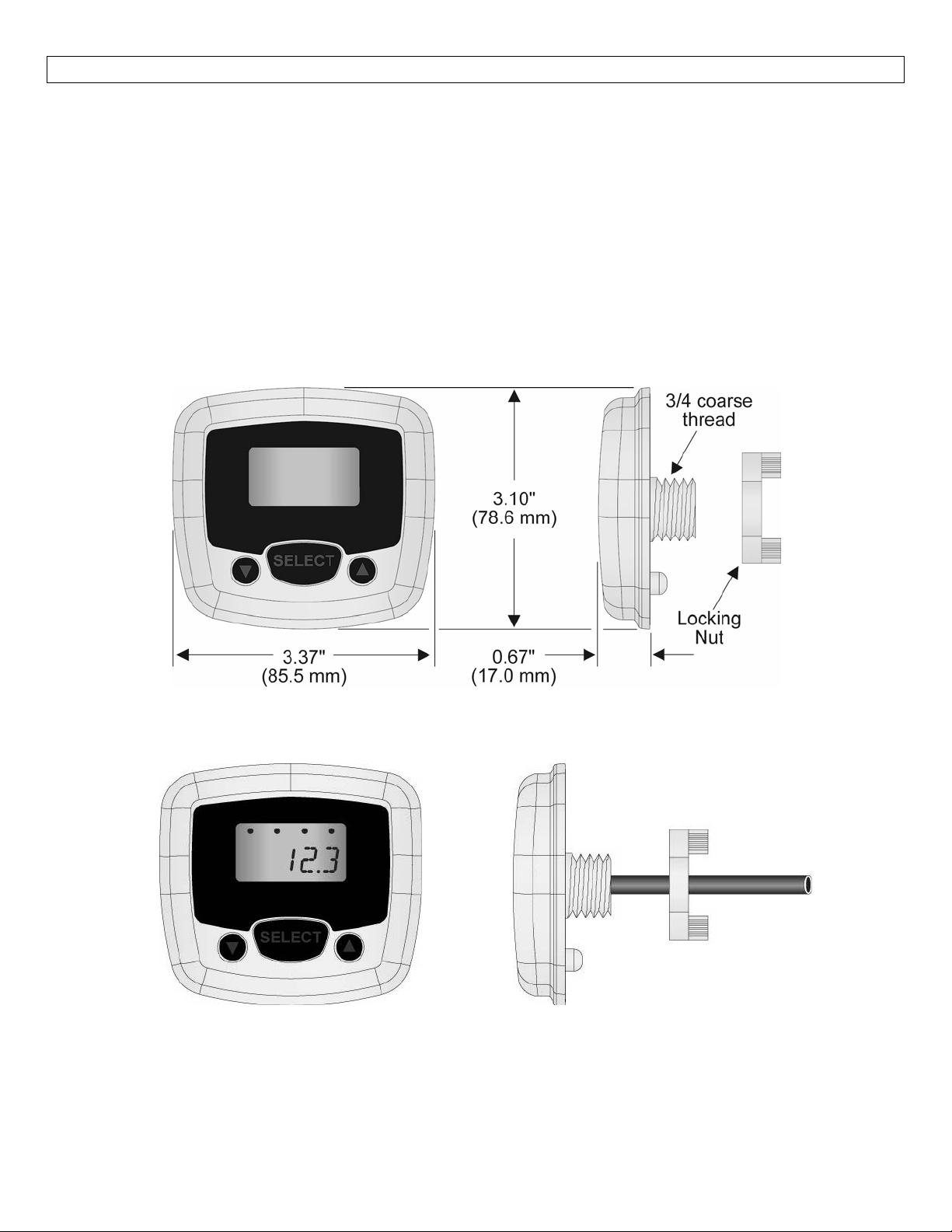
Dimensions: .........................................................................................................................................................4
Components:..............................................................................................................................................4
SafetyPrecautions:................................................................................................................................................5
GettingStarted:......................................................................................................................................................6
Wiring: .........................................................................................................................................................7
AddingaLoopPoweredDisplay:...............................................................................................................7
UnderstandingLVCN
LiquidHeightvs.Volume:..........................................................................................................................8
Linearvs.Non‐Linear:................................................................................................................................9
Example#1(VolumeOutput):.......................................................................................................9
Example#2(CurrentOutput):.....................................................................................................10
RelaySettings:.........................................................................................................................................11
Installation: .......................................................................................................................................................12
LVCN‐40SeriesGettingAround:..........................................................................................................................13
Menu:.......................................................................................................................................................13
ChangingaPumpSetPoint:.....................................................................................................................14
ChanginganAlarmSetPoint:..................................................................................................................15
Troubleshooting....................................................................................................................................................16
DisplayDescriptors:..................................................................................................................................16
‐414,LVCN‐210&LVCN‐318Seriessensors:.......................................................................8
sensor’s relay set points require
3
Page 4
SPECIFICATIONS/DIMENSIONS StepTwo
Displaytype: LCD,6‐digitwith4relay
indicators
Displayunits: Engineeringunits,liquidvolume
orheight
Displayoutput:‐9999.9to99999.9
Characterheight: 0.374"(9.5mm)
Decimalpoint: Fixed
Dotindication: Relaystatus
Userinterface: Threebutton
Sensorinput: AnyLVCN‐414,LVCN‐210&
LVCN‐318Seriessensor
Dimensions
Supplyvoltage: Providedbythelevelsensor
Operatingtemp.: F:‐4°to140°
C:‐20°to60°
Cabletype: 4‐conductor,#22AWG
Cablelength: 4'(1.2m)
Cablematerial: Polyurethane
Enclosurerating: NEMA4(IP65)whenmounted
Enclosuremat’l: Polycarbonate
Enclosuretype: Panelmount
Buttonmat’l: Siliconrubber
Compliance: CE,RoHS
IncludedComponents
LVCN‐40Seriescomeswitha4’(1.2m)cable,lockingnutandtheManual.
LVCN‐40SeriesFrontView LVCN‐40SeriesSideView
4
Page 5

SAFETYPRECAUTIONS StepThree
Aboutthis Manual:PLEASEREAD THEENTIRE MANUALPRIOR TOINSTALLING ORUSINGTHISPRODUCT.
This manual includes informationontheLVCN‐40Series level indicator from OMEGA ENGINEERING.Please
referto thepart numberlocated onthe switchlabeltoverifytheexactmodelconfiguration,whichyouhave
purchased.
User’s Responsibility for Safety:OMEGA ENGINEERING manufactures a broad range of level sensing
technologies.Whileeachofthesesensorsisdesignedtooperateinawidevarietyofapplications,itistheuser’s
responsibilitytoselectasensormodelthatisappropriatefortheapplication,installitproperly,performtestsof
the installed system, and maintain all components. The failure to do so could result in property damage or
seriousinjury.
ProperInstallationandHandling:Onlyprofessionalstaffshould installand/orrepairthisproduct.Install
the levelindicatorwith the includedlockingnut and never overtightenthe indicator withintheinstallation.
Alwayscheckforleakspriortosystemstart‐up.
WiringandElectrical:Asupplyvoltage of12to 28VDC isusedtopowerthe LVCN‐40Seriesand theLVCN‐
414,LVCN‐210&LVCN‐318Seriessensor.El ectri calwiringofthetransmittershouldbeperformedinaccordance
withallapplicablenational,state,and localcodes.
Material Compatibility:The enclosure is made of Polycarbonate (PC) with the Cable made of
PolyurethaneandtheButtonsmadeofsiliconrubber.Makesurethatthemodel,whichyouhaveselected,is
chemicallycompatiblewiththeapplicationmedia.
Enclosure: Whilethelevelindicatorhousingisliquid‐resistantthe LVCN‐40 Series is not designed to be
operationalwhenimmersed.Itshouldbemountedinsuchawaythattheenclosureandlevelindicatordonot
comeintocontactwiththeapplicationmediaundernormaloperationalconditions.
MakeaFail‐SafeSystem:Designafail‐safesystemthataccommodatesthepossibilityofLVCN‐414,LVCN‐
210&LVCN‐318Series/LVCN‐40Seriesand/orpowerfailure.OMEGAENGINEERINGrecommendstheuseof
redundantbackupsystemsandalarmsinadditiontotheprimarysystem.
Flammable, Explosive or Hazardous Applications:LVCN‐40 Series should not be used within classified
hazardousenvironments.
Safety
Installationshouldbedonebyproperlytrainedstaff
Supplyvoltageshouldneverexceedamaximumof28VDC
Makesurethesensorischemicallycompatiblewithyourapplication
Designafail‐safesystemthataccommodatesthepossibilityofsensorand/orpowerfailure
Thissensorshouldnotbeusedinclassifiedhazardousenvironments
5
Page 6
GETTINGSTARTED StepFour
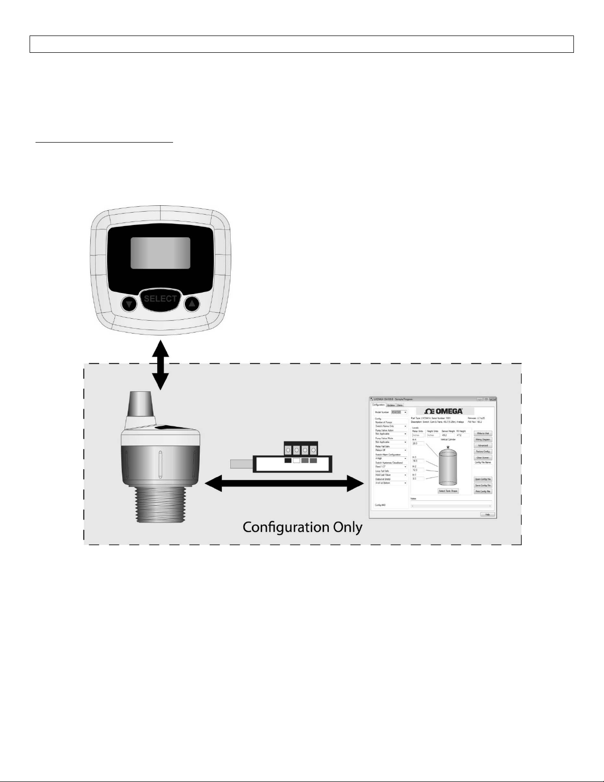
LVCN‐40Seriesdoesnotrequireanyconfiguration.LVCN‐40Serieslevelindicatorwillautomaticallyreadthe
configuration of the attached LVCN‐414, LVCN‐210 & LVCN‐318 Series sensor and display the level per the
sensor’sconfiguration.The sensordoesrequireconfigurationwiththeLVCN‐414‐SW6.0software(especially
if any relays are to be used).For a copy of the LVCN‐414‐SW 6.0 software, please go to
http://www.Omega.com/ftp
ProductsandthenclickontheLVCN414folder.BeforeattachingLVCN‐40Seriestoanysensor,configurethe
LVCN‐414,LVCN‐210&LVCN‐318Series sensortoLVCN‐414‐SW6.0software viatheFob.Oncethesensor
configured,removetheFobandattachtheLVCN‐40Series.
, click on the Flow, Level, pH, Environmental, and Pressure Section, select
is
Note:Please refertoLVCN‐414,LVCN‐210 & LVCN‐318Seriesmanualfor the wiring, configuration with the
LVCN‐414‐SW6.0softwareandinstallationofthesensor.
6
Page 7
WIRING StepFive
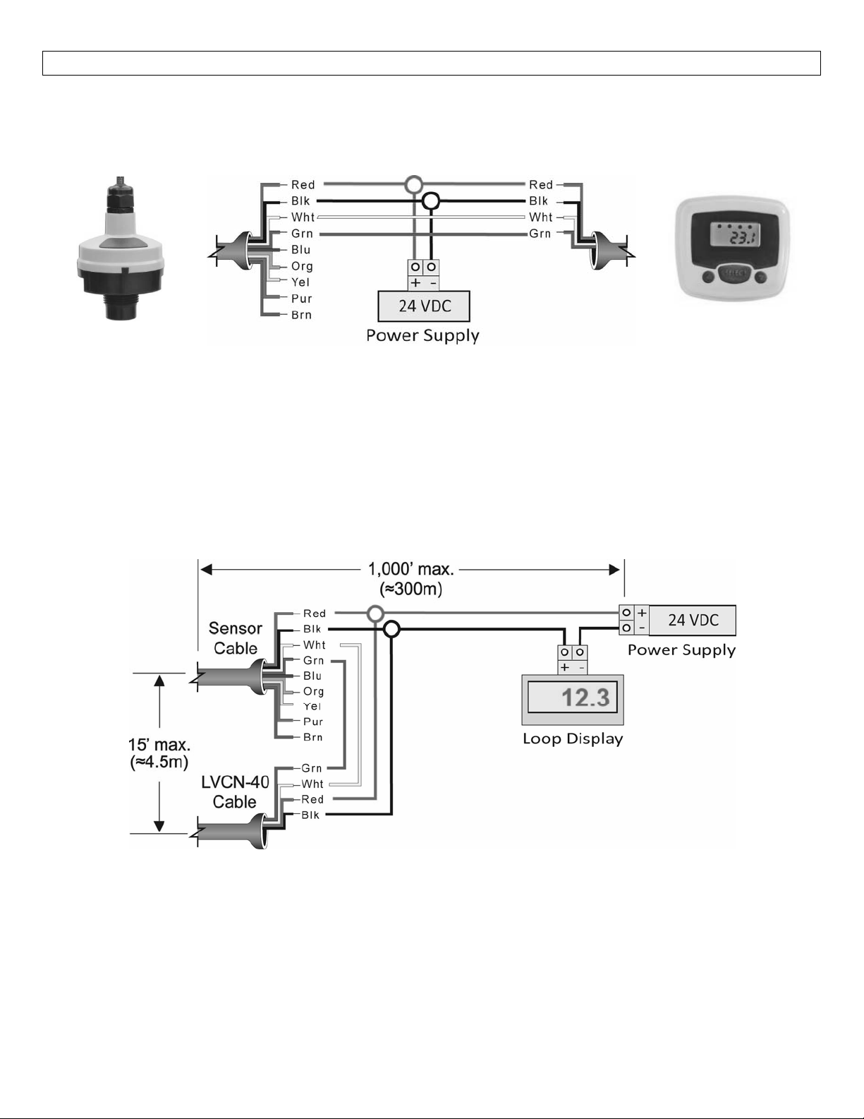
WiringLVCN‐40SeriestoanyLVCN‐414,LVCN‐210&LVCN‐318SeriesSensor:LVCN‐40Seriesandassociated
levelsensorrequirea12to28VDCpowersupplytooperate.ThemaximumcabledistancebetweenLVCN‐40
Seriesandthesensoris15’(4.5m).FollowthebelowstepstowireLVCN‐40serieswiththesensor:
Sensor
WiringidenticalforallseriesofLVCN‐414,LVCN‐210&LVCN‐318SeriesSensors.
UseonlytheRed,Black,GreenandWhitewires.
1. ConnecttheRedandBlackwiresofbothLVCN‐40Seriesandthesensortothe12‐28VDCpowersupply.
2. ConnecttheGreenandWhitewiresofLVCN‐40SeriestothecorrespondingGreenandWhitewiresofthe
sensor.
3. IsolatetheGreenandWhitewiresfromactivepowertopreventashortoftheconfigurationcircuit.
AddingaLoopPoweredDisplay
LVCN‐40Series
GeneralSafety
Wherepersonalsafetyorsignificantpropertydamagecanoccurduetoaspill,theapplicationmust
havearedundantbackupsafetysysteminstalled.
Wiringshouldalwaysbedonebyalicensedelectrician.
Supplyvoltageshouldneverexceed28VDC.
Protectthesensorfromelectricalspikesbyisolatingthepower.
Designafail‐safesystemforpossibleindicatorand/orpowerfailure.
NeverusethesensorinenvironmentsclassifiedasHazardous.
7
Page 8
UNDERSTANDINGLVCN‐40SERIES StepSix
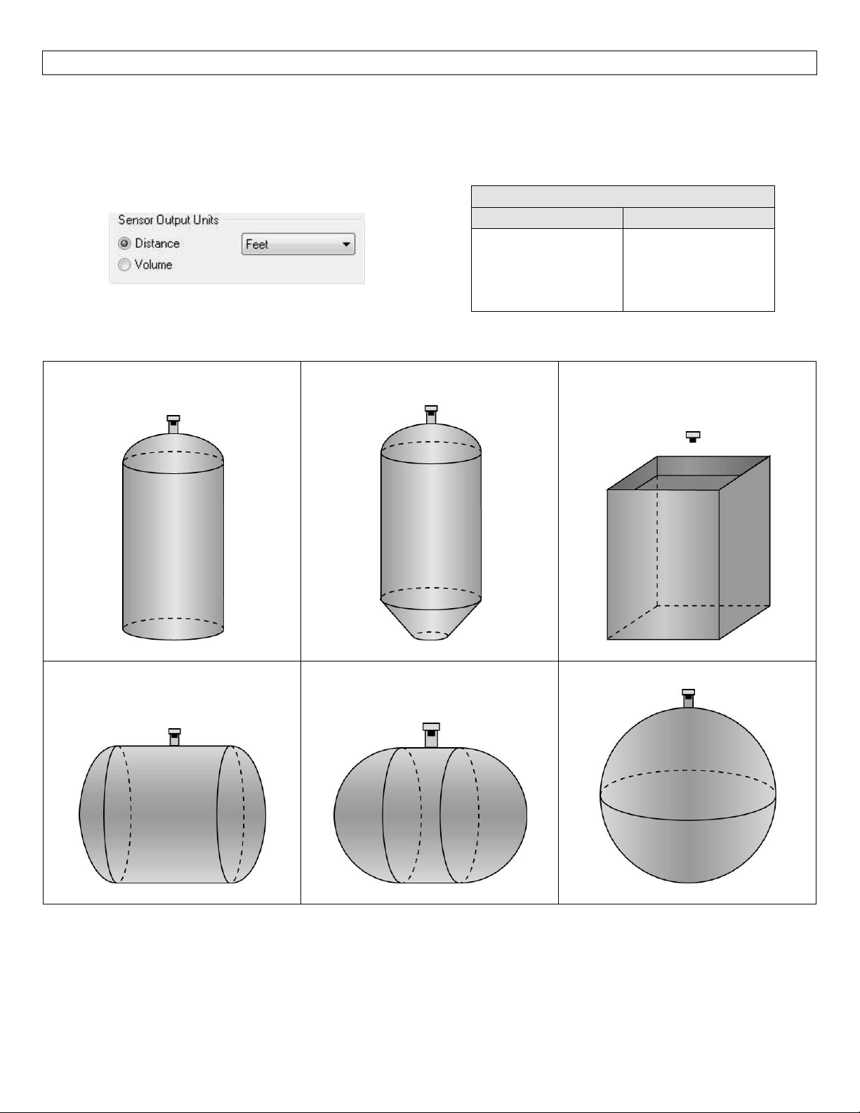
LevelHeightvs.Volume:ThelatestversionofLVCN‐414‐SW6.0softwarehasanewfeaturewhichallowsthe
sensor tobeconfigured to read eithertheheightof the liquid or thevolumeofthe liquid.This selection is
made under the Sensor Output Units selection of either Volume (volume of liquid) or Distance (height of
liquid).SeethechartbelowfortheengineeringunitoptionsavailableforbothDistanceandVolume.
UnitsofMeasurement
Distance Volume
Inches
Cm
Feet
Meters
Gallons
Liters
Thereare6differenttankshapesthatyoucanselectwithLVCN‐414‐SW6.0Software.
VerticalCylinderTank
HorizontalCylinderTank
withEndCaps
VerticalCylinderTank
withConeBottom
HorizontalCylinderTank
withSphericalEndCaps
RectangularTank
SphericalTank
8
Page 9
UNDERSTANDINGLVCN‐40SERIES StepSix
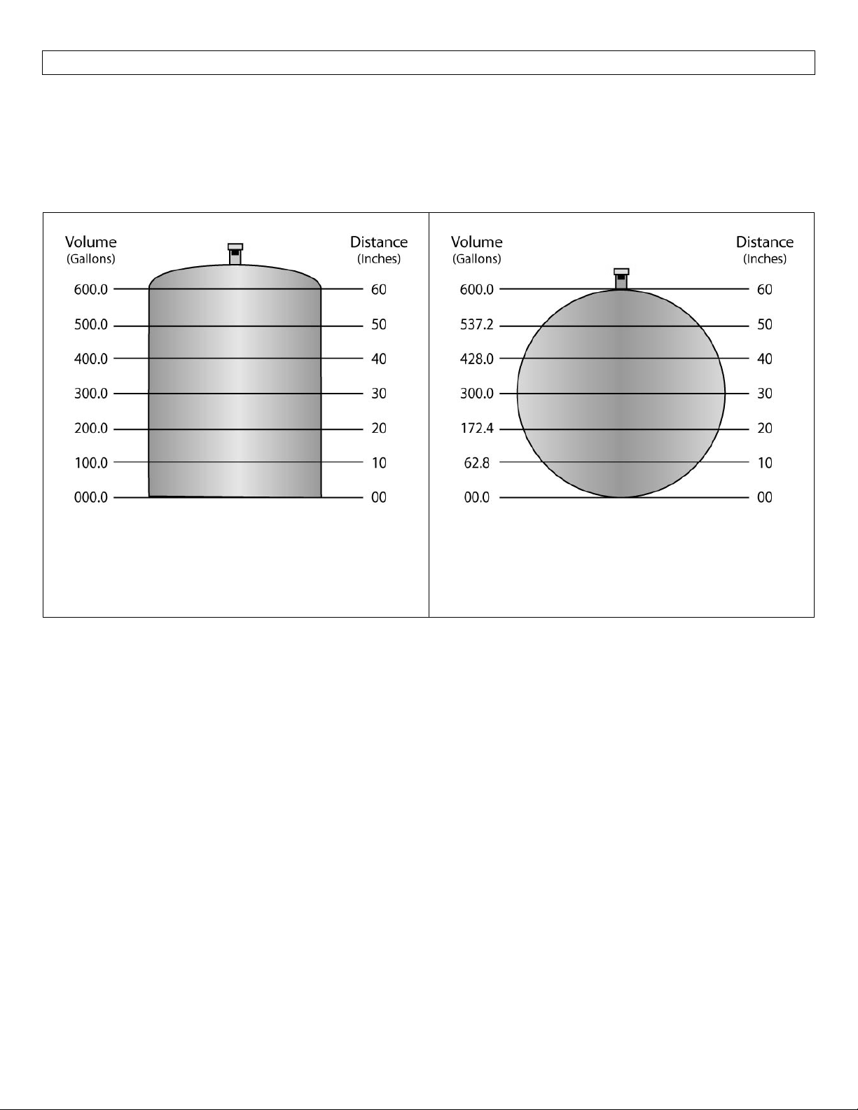
Linearvs.Non‐Linear:Twooftheshapes(Vertical CylinderTankandRectangularTank) willalwaysprovidea
linearoutput,regardless ofselectingDistance orVolume.Theremainingfourshapes (VerticalCylinderTank
withConeBottom,HorizontalCylinderTankwith EndCaps, HorizontalCylinder TankwithSphericalEndCaps
andSphericalTank)willhavealinearoutputwhenDistanceisselected,butwillhaveanon‐linearoutputwhen
volumeisselected.
VerticalCylindricalTank
HorizontalCylinderTankwithEnd
Caps
In the above illustration, 10” of liquid will always
beequalto100gallonsofliquid(1”=10gallons).
Whenvolumeisselected,the4‐20mAoutputfromthesensorwillbe proportionaltothevolumeofthetank,
nottheheightofthetank.Thismeansthatthecurrentoutputwilltrackthevolumeofthetank(ingallonsor
liters) within a non‐linear tank(VerticalCylinder
Caps,HorizontalCylinderTankwithSphericalEndCapsorSphericalTank).
Whenconnecting the4‐20 mAoutput toa display,the currentsignalwillfollowthevolumeofthetank.The
displaywillalsoreflectthevolumeofthetank
Example#1(VolumeOutput):Intheillustrationsabove,@20”ofliquid,thedisplaywillshow200.0gallonsin
theVerticalCylindrical Tank.However, intheHorizontal CylinderTankwith EndCaps,the same levelof20”
wouldshow172.4gallons.
Tank with ConeBottom,HorizontalCylinderTank with End
andnottheheightoftheliquid.
In the above illustration, 10” of liquid does not
equal 100 gallons.The 10” at the bottom
representsariseof62.8gallonswherethechange
between 10” and 20” represents an increase of
109.6gallons.
9
Page 10
UNDERSTANDINGLVCN‐40SERIES StepSix
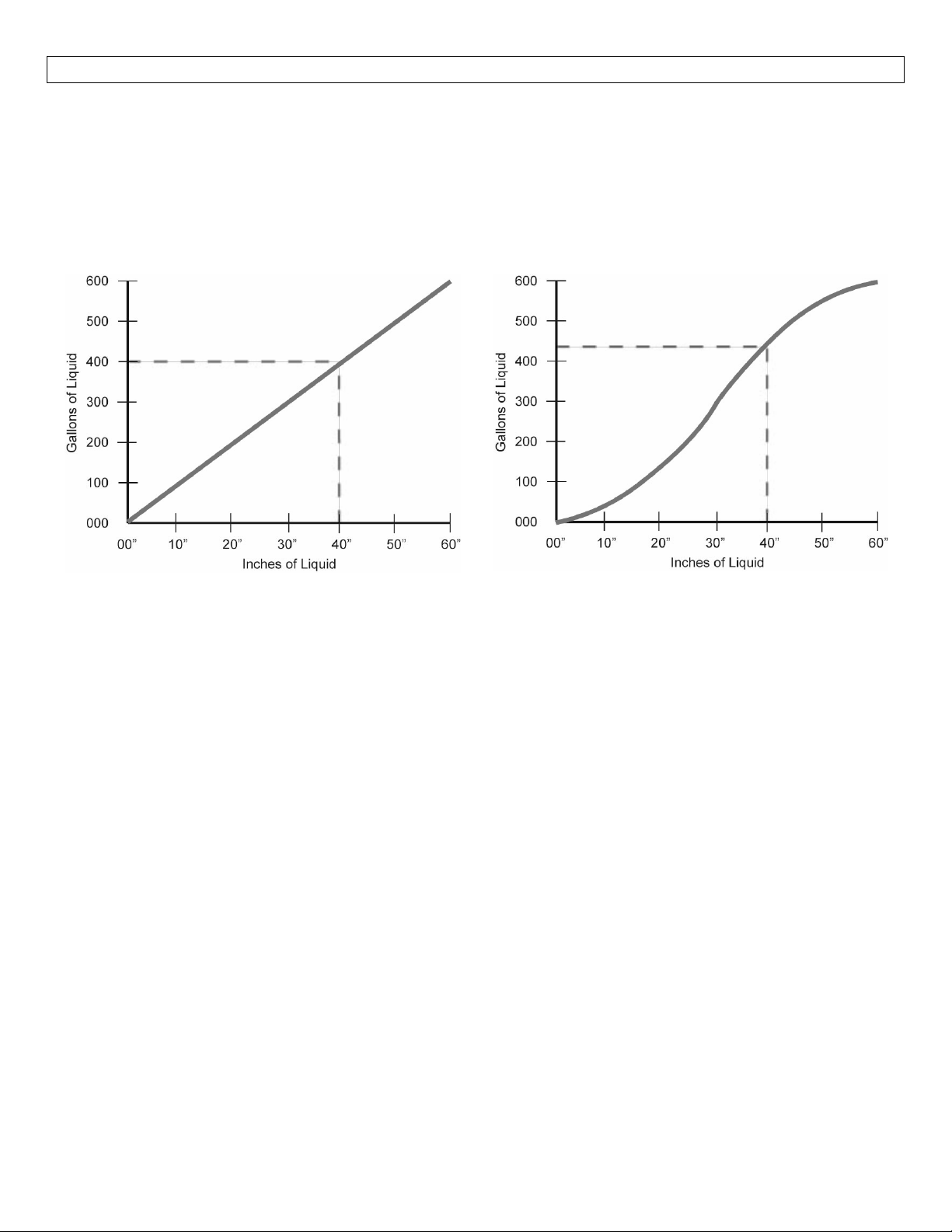
Example#2(Current Output):inthe illustrationsbelow,the 4mA signalisset at0”(0.0 gallons)andthe 20
mAsignalissetto60”(600.0gallons).IntheVerticalCylindricalTank,40”ofliquidwilloutputacurrentsignal
of 14.67mA.However, in the Horizontal Cylindrical Tank withEnd Caps, 40” of liquid will output a current
signal of 15.41mA.A simple loop display set with 4mA = 0 gallons and 20 mA = 600 gallons willshowtwo
differentvolumesbaseduponthetankshape configuration.VerticalCylindrical Tankwill show400.0gallons
whileHorizontalCylindricalTankwith
EndCapswillshow428.0gallons.
VerticalCylindricalTank
10”ofliquid willalwaysbe equalto100 gallons
ofliquid(1”=10gallons).
1”ofliquiddoes not equal 10 gallons.The 10”
HorizontalCylinderTankwithEndCaps
at the bottom represents a rise of
where the change between 10” and 20”
representsanincreaseof109.6gallons.
62.8 gallons
10
Page 11
UNDERSTANDINGLVCN‐40SERIES StepSix
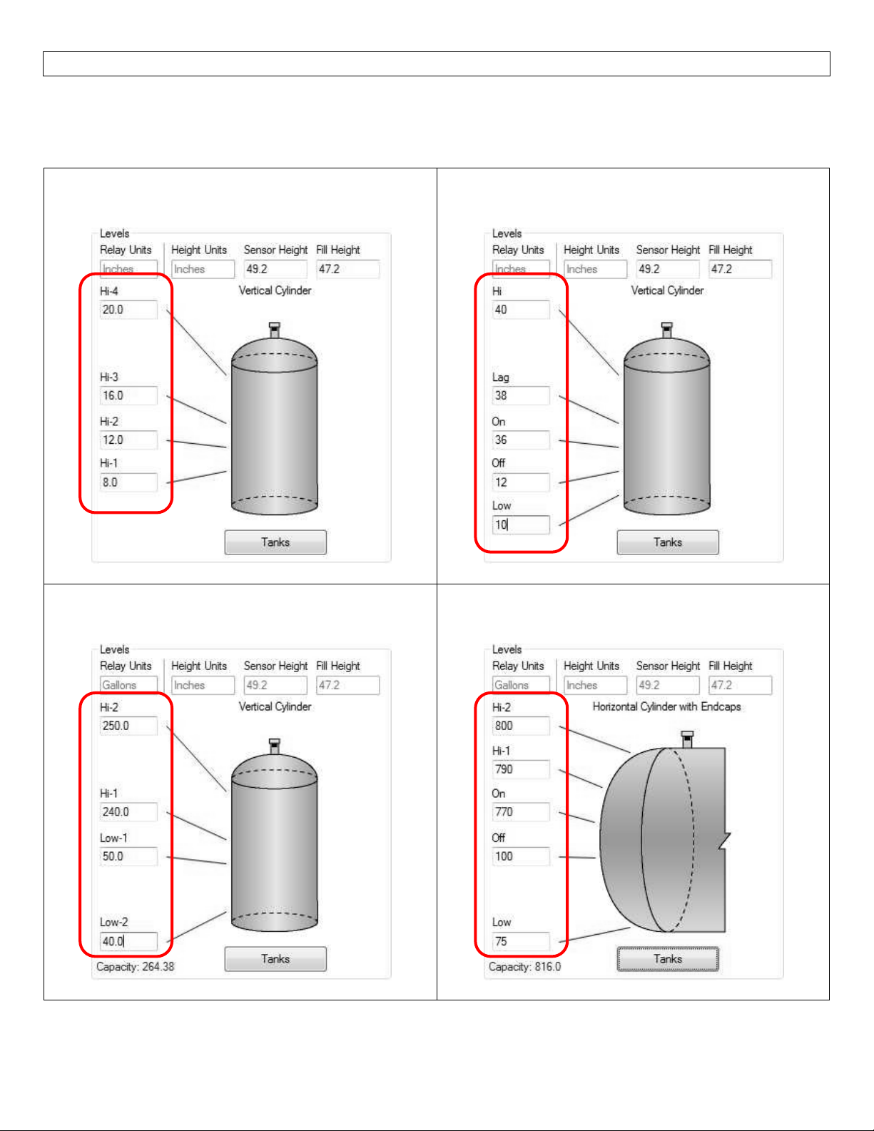
Relay Settings:LVCN‐40 Series not only displays the level reading oftheLVCN‐414,LVCN‐210&LVCN‐318
Seriessensor(HeightorVolume),butLVCN‐40Seriesalsoallowsyoutoadjustthesettingsforrelays.LVCN‐40
SerieswillnotallowchangestoSensorHeightorFill‐Height,justtherelaysettings.
The sensor configuredtoreadinches of liquid plus 4
highalarmrelays.
The sensor configured to read inches of liquid plus
duplexrelaysandhighandlowalarmrelays.
Thesensorconfigured toreadgallons ofliquidplus 2
highalarmand2lowrelays.
Thesensorconfiguredtoreadgallonsofliquidplusan
autoemptyrelaysandhighandlowalarmrelays.
11
Page 12
INSTALLATION StepSeven
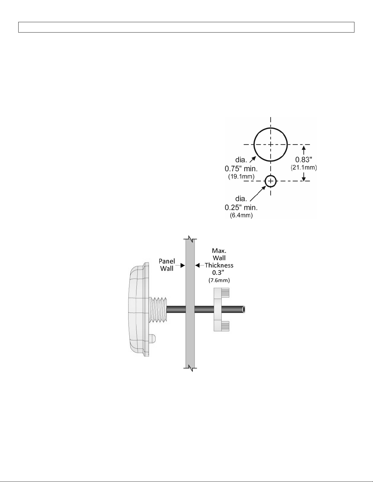
LVCN‐40Series isdesignedfortypicalpanelmountinstallations,eitherlocatedwithinaninstrumentpanelor
throughthewallofaNEMAboxenclosure.
Panel Mount: The maximum cable distance between LVCN‐40 Series and LVCN‐414, LVCN‐210 & LVCN‐318
Seriessensoris15’(4.5m).Follow thebelow
locatednearthesensor:
1. Drill(1)large0.75”(19.1mm)diameterholeinthe
panelforthecableandnipple.
2. Drill (1) small 0.25” (6.4mm) diameter hole 0.83”
(21.1mm) below the large hole that will prevent
the
installedindicatorfromrotatingoffcenter.
3. Runtheindicatorcablethroughthelargetophole
andlockingnut(ontherearsideofthepanel).
4. Properly align the indicator with the flat gasket
and holes on the panel. Then press the indicator
inplaceagainstthepanel.
stepsto installtheindicator ina panelorNEMA boxenclosure
5. Tighten thelocking nutdownover thenippleand
routethecablefortermination.
12
Page 13
GETTINGAROUNDLVCN‐40SERIES StepEight
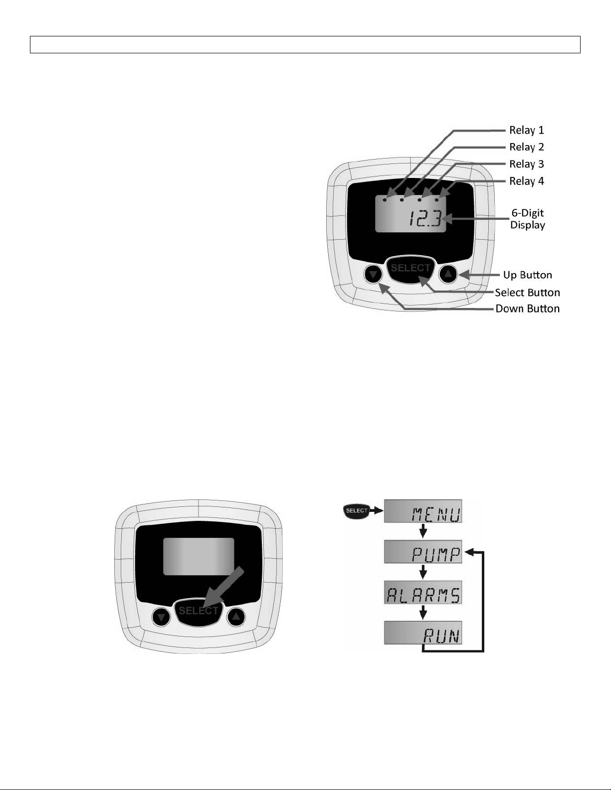
LVCN‐40Seriesfeaturesa6‐digitdisplaywithrelayindicatorsandathree‐buttonuserinterface.Theindicator
displays themeasuredvalue and relay statusoftheconnected sensor (if thesensorhasrelays and they are
configuredforuse).
Relay 1‐4 – Indicates when the sensor’s relay is
energized.Note: Not all LVCN‐414 series sensor
modelshaverelays.
o If the sensor does not have any relays, then
theindicatorswillremainoff.
6‐digit Display – Shows the liquid level in height
(inches, cm, feet or meters) or the volume of
liquid(gallonsorliters).
o Theselectionofheightvs.volumeissetinthe
LVCN‐414‐SW6.0software.
UpButton–Usedtoincreaseasetpointvalue.
Select Button – Used to enter the Menu and
acceptvalues.
Down Button – Used to decrease a set point
value.
Note:To increase the scrolling speed of the display,
hold down the SELECT button while simultaneously
pressingtheUPorDOWNbutton.
Entering the MENU:If desired, users can change the sensor’s relay ALARM, VALVE or PUMP ON‐OFF set
pointsusingLVCN‐40 Series.Toenter themenuLVCN‐40 SeriesMENUfunctions,press andhold theSELECT
button for 5 seconds.TheMENUwillthenscroll between theconfiguredPUMP,ALAMRSand RUN modes.
Note:IftherelaysareconfiguredforPUMPSandALARMS,thenbothwillappearinthemenu.Iftherelaysare
configuredforAlarmsonly,thenPUMPwillnotappear.Iftherelays areconfigured forPUMPS only(also for
valves),thenALARMSwillnotappear.
Tochangeapumpsetpointvalue,pressSELECTwhenPUMPappears.
TochangeanAlarmsetpointvalue,pressSELECTwhenALARMSappear.
Toexitthemenuandreturntorunmode,pressSELECTwhenRUNappears.
13
Page 14
GETTINGAROUNDLVCN‐40SERIES StepEight
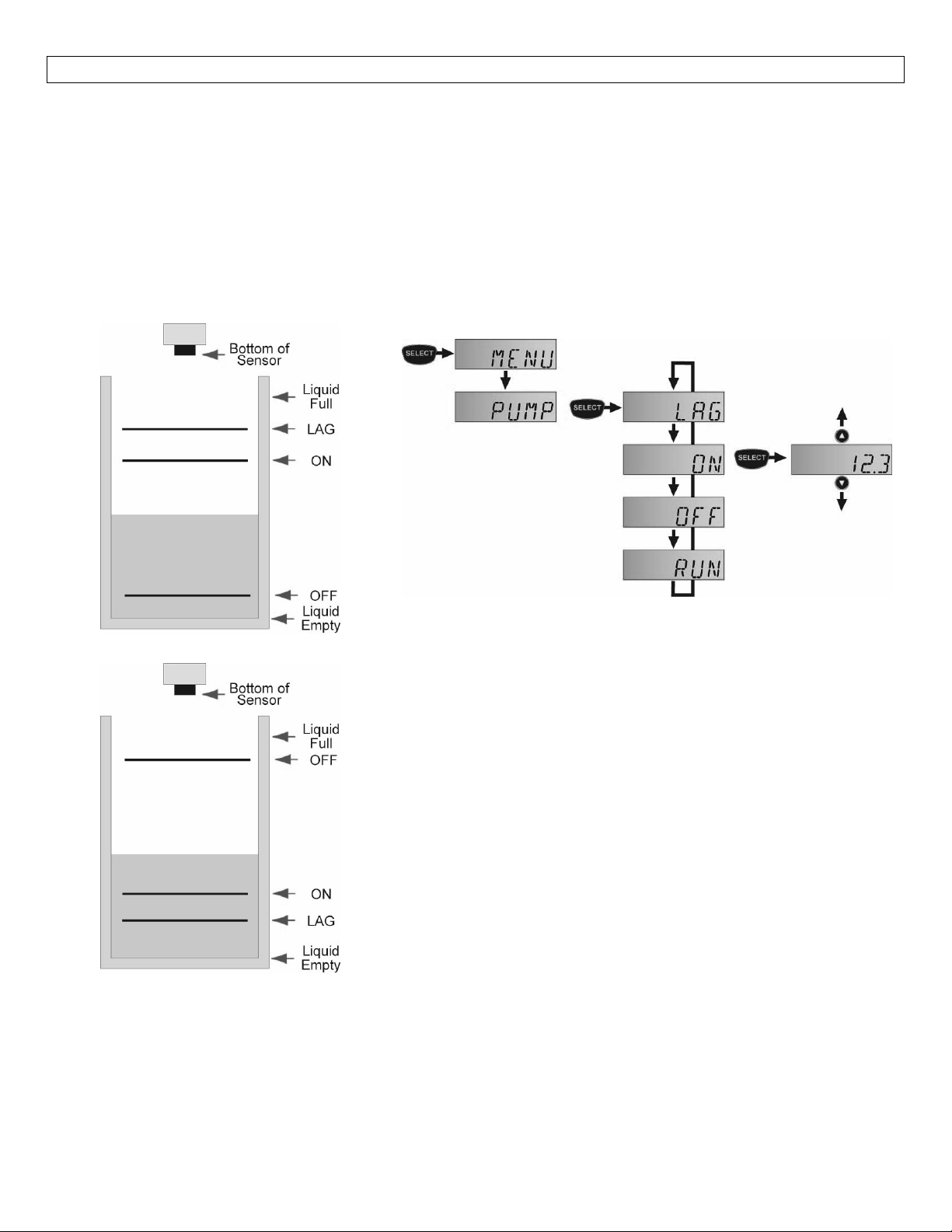
ChangingaPumpSetPoint:Sensors(LVCN‐414,LVCN‐210&LVCN‐318Series)withrelayshave(1‐4)channels
activeontheLVCN‐40Series.IfafteraccessingtheMENU,PUMPappearsinthedisplay,thenatleast(1)relay
isconfigured forpump orvalve control.Simplexpumpcontrolhas(1)ONand(1)OFFsetting.Duplexpump
control(2‐pumps)hasathirdadditionalLAGsetting.Note:Priortomakinganychanges,werecommendthat
you write down all existing set point values.The example below highlights a duplex pump system in an
automatic empty or automatic fill operation with (1) LAG, (1) ON and (1) OFF set point.Use the following
stepstochangeyoursimplexorduplexpumpcontrolsettings.
AutomaticEmptyOperation
AutomaticFillOperation
TechTips
Neverplacearelaysetpoint(ON,OFF,LAG)attheliquidemptyorliquidfullposition.Youshould
atleastsomedistanceorvolumebufferseparatingthem.Forexample,ina500gallontank,therelay
setpointscouldbeplacedat≥10gallonsor≤490gallons.
StepstoChangePumpSet Points
1. HoldSELECTfor5secondstoentertheMENU.
2. PressSELECTwhenPUMPappears.
3. PressSELECTwhenthesetpoint(ON,OFF,LAG)youwantto
changeappears.
4. PresstheUPandDOWNbuttonstoincreaseordecreasethe
setpointtothedesiredvalue.Toscrollfaster,holdSELECT
whilepressingUPorDOWN.
5. Toenterthesetpoint,holdSELECTfor2seconds.
6. Tochangeanothersetpoint,pressSELECTwhentheset
pointappears.
7. ToexittheMENU,pressSELECTwhenRUNappears.
have
14
Page 15
GETTINGAROUNDLVCN‐40SERIES StepEight
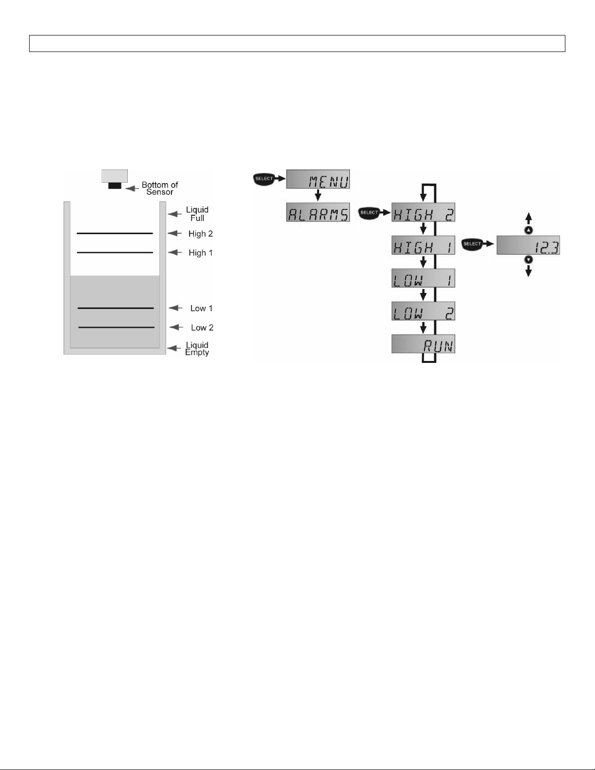
Changing an Alarm Set Point:Sensors (LVCN‐414, LVCN‐210 & LVCN‐318 Series) with relays have (1‐4)
channelsactiveon theLVCN‐40Series.Ifafteraccessing theMENU,ALARMS appearsin thedisplay,thenat
least(1) relayisconfiguredas analarm.The Alarmsettings maybeinanycombinationofLOWand/or HIGH
alarms(4‐HIGH,1‐LOW&3‐HIGH,2‐LOW&2‐HIGH,etc.).Note:Priortomakinganychanges,werecommend
that youwritedownallexisting set point values.The examplebelowhighlightsa 2‐LOW and 2‐HIGH alarm
operationwith(4)setpoints.Usethefollowingstepstochangeyouralarmsettings.
StepstochangeAlarmsettings:
1. HoldSELECTfor5secondstoentertheMENU.
2. PressSELECTwhenALARMSappears.
3. PressSELECTwhenthesetpoint(HIGH2,HIGH1,LOW1,LOW2)youwanttochangeappears.
4. Press the UP and DOWN buttons to increase or decrease the set point to the desired value.To scroll
faster,holdSELECTwhilepressingUPorDOWN.
5. Toenterthesetpoint,holdSELECTfor2seconds.
6. Tochangeanothersetpoint,pressSELECTwhenthesetpointappears.
7. ToexittheMENU,pressSELECTwhenRUNappears.
Hints:
Neverplacearelaysset point (High 1, Low 1) at the liquid emptyorliquidfullposition.Youshould
haveat leastsomedistanceorvolumebuffer separatingthem.Forexample,ina 500gallon tank,the
relaysetpointscouldbeplacedat≥10gallonsor≤490gallons.
15
Page 16
TROUBLESHOOTING StepNine
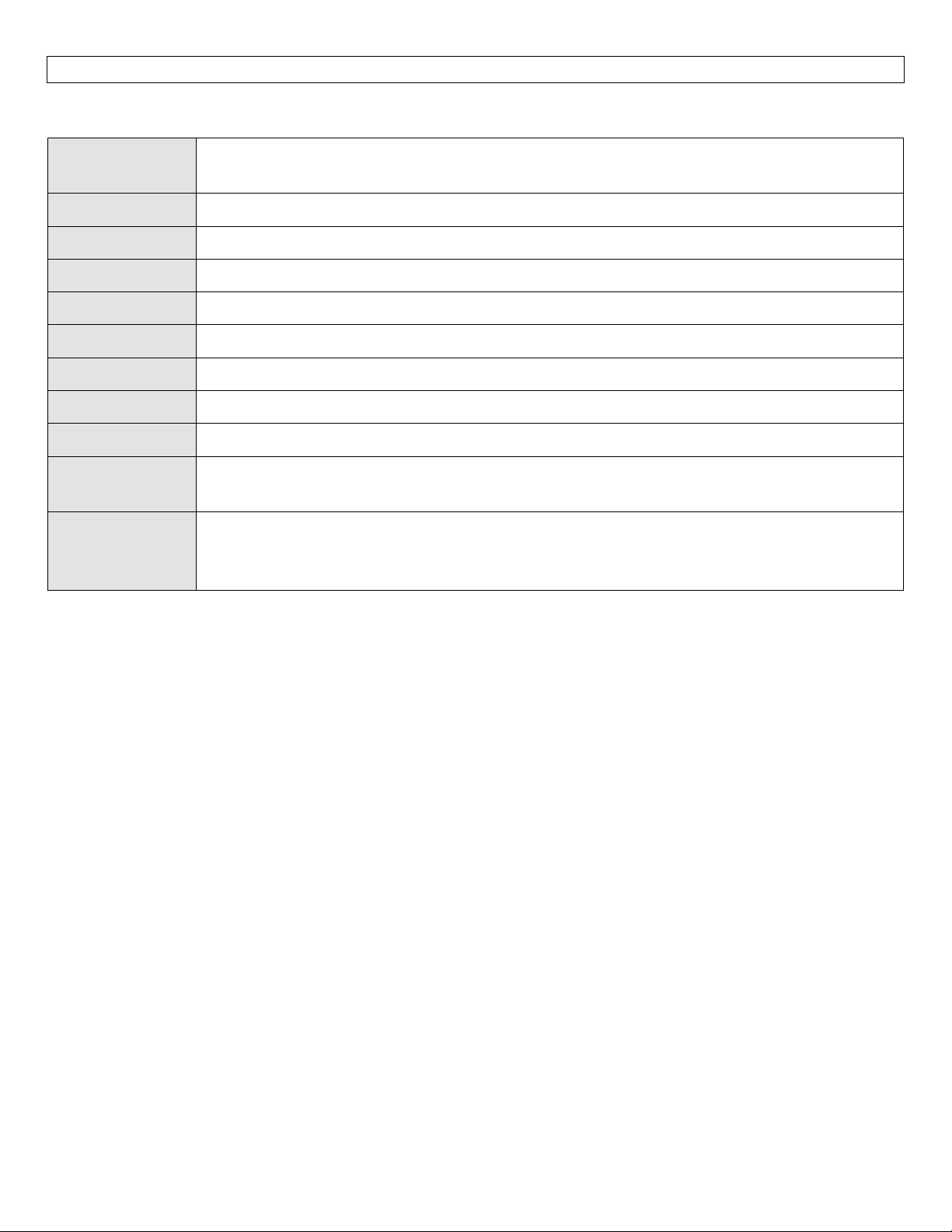
DisplayDescriptors:Thefollowingarethedisplay’soperationaldescriptors,meaningandcorrectiveaction:
WARMUP
MENU Indicatesthemenuforconfigurationofrelaysetpoints.
PUMP PUMPistheidentifierfortherelaysetpointsaffectingPumporValveoperations.
OFF OFFistherelaysetpointthatturnsOFFthepump.
ON ONistherelaysetpointthatturnsONthepump.
LAG LAGisthesetpointthatturnsONthelagpump.
ALARM AlarmistheidentifierfortherelaysetpointsaffectingAlarmoperations.
HIGH# HIGH#istherelaysetpointthatenergizesahighalarmrelay.
LOW# LOW#istherelaysetpointthatenergizesalowalarmrelay.
CHECKWIRES
UPDATEFWREV
WARMUPisseenwhenpowerisfirstappliedtothesensorandLVCN‐40Series.WARMUP
indicatesthatthedisplayiswaitingforthesensortoacquireandsendavalidlevelreading.
NotAllfourwiresareproperlyconnectedtothesensor.Checkthewiringbetweenthe
LVCN‐40Seriesandthelevelsensor.
Theattachedsensorisnotrunningaversionofthefirmware(50.0orhigher)thatis
compatiblewithLVCN‐40Series.ConnecttheLVCN‐414,LVCN‐210orLVCN‐318Seriesto
theLVCN‐414‐SW6.0softwareandupdatethefirmware.
16
Page 17

17
Page 18

18
Page 19

19
Page 20

20
 Loading...