

Page 1
1 2
Page 2

Page 3

INTRODUCTION/TABLEOFCONTENTS StepOne
The small tank sensor is an innovative level sensor family that replaces float, conductance and pressure
sensors that fail due to contact with dirty, sticking and scaling media in small (< 4’/1.25m) to medium
(<18’/5.5m)talltanks.Appliedinskid,machine,toolandprocessapplications, the general purpose sensors
areavailablewithsingleandmulti‐functioncapabilitiesincludingmeasurement,switchingandcontrol.
NewFeatures
Easilychangeoutputfromdistancetovolume
Selectfrom6standardtankshapesora16pointstrappingtableforcustomer/oddsizetanks
TableofContents
Specifications:.........................................................................................................................................................4
Dimensions: .........................................................................................................................................................5
SafetyPrecautions:................................................................................................................................................6
Components: .........................................................................................................................................................7
GettingStarted:......................................................................................................................................................8
USB®FobInterface:...............................................................................................................................
LVCN414‐SWSoftware:..........................................................................................................................................9
1.OutputConfiguration:..........................................................................................................................10
LVCN414,LVCN210,LVCN318,LVCN414‐Rseries:......................................................................10
LVCN414‐Iseries:........................................................................................................................17
LVCN414‐Vseries:........................................................................................................................19
2.TankShapeSelection:..........................................................................................................................22
3.LevelConfiguration:.............................................................................................................................27
4.WritetoUnit:.......................................................................................................................................29
Wiring: .......................................................................................................................................................30
WiringDiagram:.......................................................................................................................................30
WireConnections:....................................................................................................................................31
SwitchInductiveLoads:............................................................................................................................32
Installation: .......................................................................................................................................................33
MountingGuide:......................................................................................................................................33
FittingSelection:......................................................................................................................................34
TankAdapter:...............................................................................................................................34
Riser:............................................................................................................................................34
Flange:..........................................................................................................................................35
SideMountFitting:......................................................................................................................35
StandPipe:...................................................................................................................................36
AdvancedFeature:...............................................................................................................................................37
Appendix: .......................................................................................................................................................38
SampleProgram:......................................................................................................................................38
UpdatingSoftware:..................................................................................................................................39
UpdatingTransmitterFirmware:.............................................................................................................40
StrappingTable:.......................................................................................................................................41
Linervs.Non‐Linear:................................................................................................................................42
Troubleshooting....................................................................................................................................................44
FactoryDefaults........................................................................................................................................44
DemoPage:..............................................................................................................................................45
SolutionTable:.........................................................................................................................................46
....8
3
Page 4

SPECIFICATIONS StepTwo
Range: LVCN414‐I/LVCN414/LVCN414‐
R/LVCN414‐V:49.2”(1.25m)
LVCN210:9.8’(3.0m)
LVCN318:18.0’(5.5m)
Accuracy: LVCN414‐I/LVCN414/LVCN414‐
R/LVCN414‐V:0.125”(3mm)
LVCN210:+/‐0.2%ofrange
LVCN318:+/‐0.2%ofrange
Resolution: LVCN414‐I/LVCN414/LVCN414‐
R/LVCN414‐V:0.019”(0.5mm)
LVCN210:0.039”(1mm)
LVCN318:0.079”(2mm)
Deadband: LVCN414‐I/LVCN414/LVCN414‐
R/LVCN414‐V:2”(5cm)
LVCN210:4”(10cm)
LVCN318:8”(20cm)
Beamwidth: LVCN414‐I/LVCN414/LVCN210/
LVCN414‐R/LVCN414‐V:2”(5cm)
dia.
LVCN318:3”(7.6cm)dia.
Configuration: LVCN414‐SW(software)PC
WindowsUSB®2.0
Memory: Non‐volatile
Supplyvoltage: LVCN414‐I/LVCN414/LVCN210/
LVCN318:24VDC(loop)
LVCN414‐R:12‐24VAC/VDC
LVCN414‐V:12‐28VDC
Consumption: 0.5W
Loopresistance: LVCN414‐I/LVCN414/LVCN210/
LVCN318:400Ohmsmax
Signaloutput: LVCN414‐I/LVCN414/LVCN210/
LVCN318:4‐20mA,two‐wire
LVCN414‐V:0‐5V,0‐10V,976‐
2000Hz
Frequency: LVCN414‐Vonly:sinkcurrent,15
mAnominal
Signalinvert: LVCN414‐I/LVCN414/LVCN210/
LVCN318:4‐20mAor20‐4mA
LVCN414‐V:5‐0V,10‐0V,2000‐
976Hz
Signalfail‐safe: LVCN414‐I/LVCN414/LVCN210/
LVCN318:4mA,20mA,21mA,22
mAorholdlast
LVCN414‐V:Full,emptyorhold
last
Contacttype: LVCN414/LVCN210/LVCN318/
LVCN414‐R:(4)SPSTrelays
Contactrating: LVCN414/LVCN210/LVCN318/
LVCN414‐R:60VA,1Amaximum
Contactfail‐
safe:
LVCN414/LVCN210/LVCN318/
LVCN414‐R:Powerloss:Holdlast,
Poweron:Open,closeorholdlast
Hysteresis: LVCN414/LVCN210/LVCN318/
LVCN414‐R:Selectable
Processtemp.: F:20°to140°
C:‐7°to60°
Temp.comp.: Automatic
Ambienttemp.: F:‐31°to140°
C:‐35°to60°
Pressure: MWP=30PSI
Enclosurerating: Type6Pencapsulated,corrosion
resistance&submersible
Encl.material: Polycarbonate
Strainrelief
ThermoplasticElastomer(TPE)
mat’l.:
Trans.material: PVDF
Cablejacket
Polyurethane
mat’l:
Cabletype: 9‐conductor,shielded
Cablelength: 48”(1.2m)
Processmount: LVCN414‐I/LVCN414/LVCN414‐
R/LVCN414‐V/LVCN210:1”NPT
LVCN318:2”NPT
Mountgasket: FKM
Classification: Generalpurpose
Compliance: CE,RoHS
4
Page 5
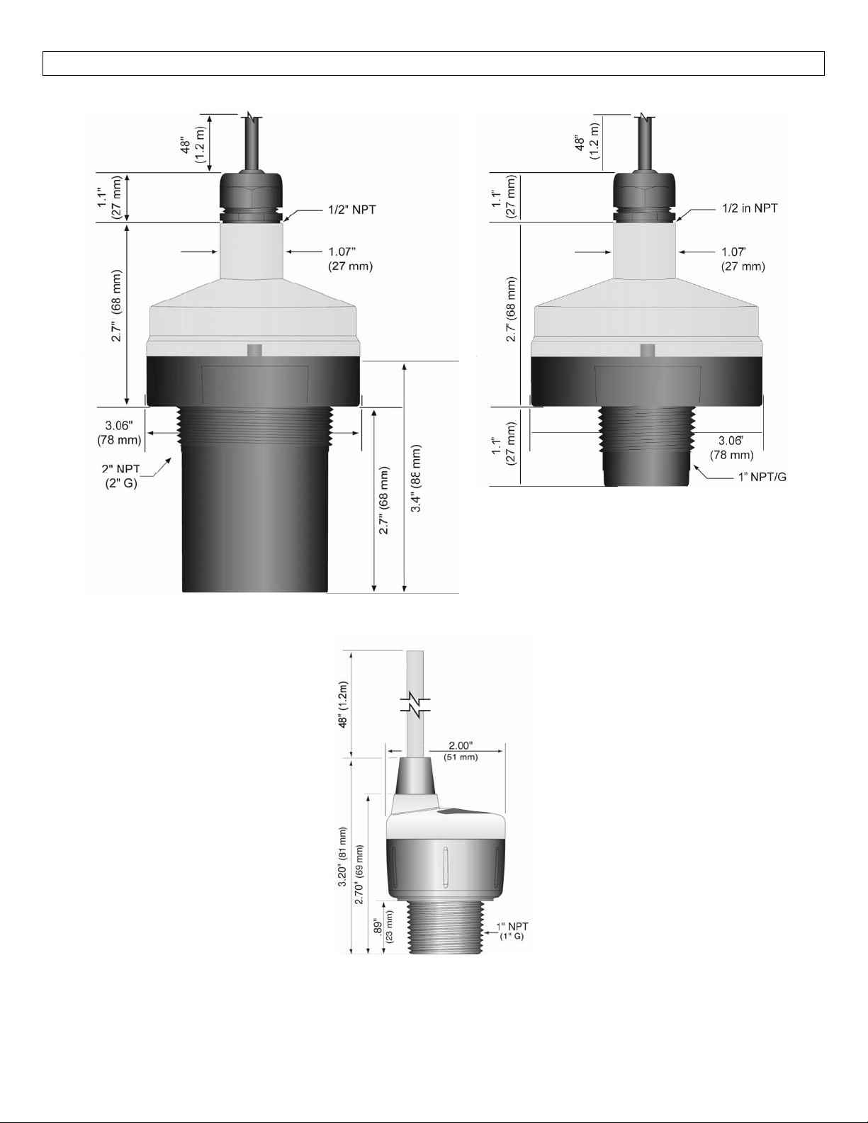
DIMENSIONS StepThree
LVCN318Series LVCN210Series
LVCN414‐I,LVCN414,LVCN414‐R&LVCN414‐VSeries
5
Page 6
SAFETYPRECAUTIONS StepFour
About this Manual:PLEASE READ THE ENTIRE QUICK START PRIOR TO INSTALLING OR USING THIS
PRODUCT.Thismanualincludesinformation onthesmalltank seriesUltrasonicLevelSwitch,controllerand
transmitterfromOMEGAENGINEERING.Pleaserefertothepartnumberlocatedontheswitchlabeltoverify
theexactmodelconfiguration,whichyouhavepurchased.
User’s Responsibility for Safety:OMEGA ENGINEERING manufactures a broad range of level sensing
technologies. While each ofthesesensors is designed to operateina wide variety ofapplications,it is the
user’sresponsibilitytoselectasensormodelthatisappropriatefortheapplication,installitproperly,perform
tests of the installed system, and maintain all components. The failure to do so could result in property
damageorseriousinjury.
ProperInstallationandHandling:Onlyprofessionalstaffshouldinstalland/orrepairthisproduct.Install
thetransmitterwiththeincludedFKMgasketandneverovertightenthetransmitterwithinthefitting.Always
checkforleakspriortosystemstart‐up.
WiringandElectrical:Asupplyvoltageof12to28VDC(VACforLVCN414‐Rseriesonly)isusedtopower
the ultrasonic sensor.Electrical wiring of the transmitter should be performed in accordance with all
applicablenational,state,andlocalcodes.
Material Compatibility:The enclosure is made of Polycarbonate (PC).The transducer is made of
PolyvinylideneFluoride(PVDF).Makesurethatthemodel,whichyouhaveselected,ischemicallycompatible
withtheapplicationmedia.
Enclosure: While thetransmitter housing is liquid‐resistanttheUltrasonic sensor is notdesignedto be
operationalwhenimmersed.Itshould bemountedinsucha waythattheenclosureand transducerdonot
comeintocontactwiththeapplicationmediaundernormaloperationalconditions.
Safety
Installationshouldbedonebyproperlytrainedstaff
Supplyvoltageshouldneverexceedamaximumof28VDC
Makesurethesensorischemicallycompatiblewithyourapplication
Designafail‐safesystemthataccommodatesthepossibilityofsensorand/orpowerfailure
Thissensorshouldnotbeusedinclassifiedhazardousenvironments
Make a Fail‐Safe System:Design a fail‐safe system that accommodates the possibility of transmitter
and/orpowerfailure.OMEGAENGINEERINGrecommendsthe useofredundantbackupsystemsandalarms
inadditiontotheprimarysystem.
Flammable, Explosive or Hazardous Applications:The sensor should not be used within classified
hazardousenvironments.
Warning: Always use the FKM gasket when installing the ultrasonic sensor, and make sure that all
electricalwiringoftheswitchisinaccordancewithapplicablecodes.
6
Page 7
COMPONENTS StepFive
Thesmalltankultrasonicsensor isofferedindifferentmodels.Dependingon themodelpurchased,youmay
ormaynothavebeen shippedallthecomponentsshown below.Youdohowever, needasensor,USB®Fob
andFKMgaskettoconfigure,installandoperatetheultrasonicsensor.
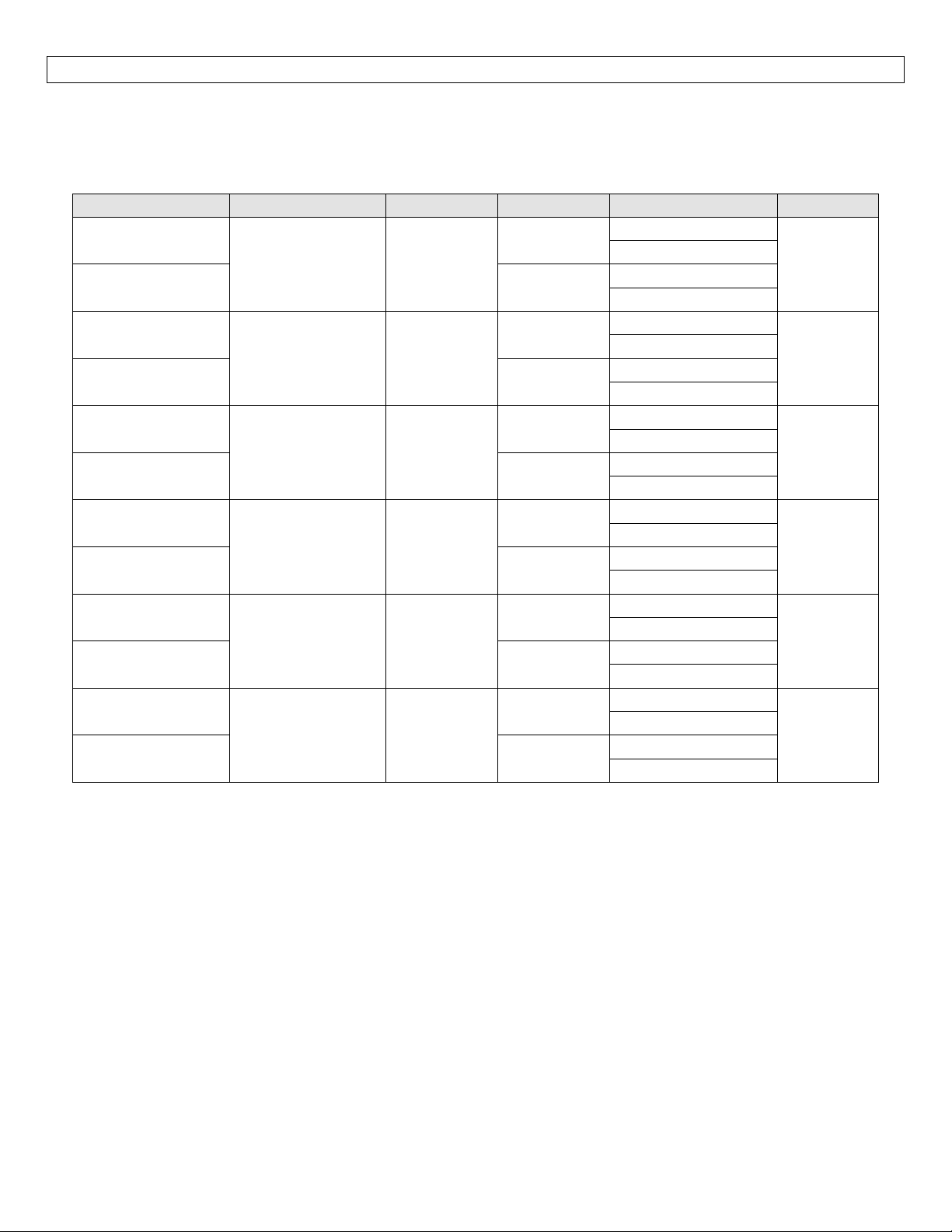
P/N Max.Range DeadBand Thread Fob *Outputs
LVCN414‐I‐B
LVCN414‐I
LVCN414‐I‐G‐B
LVCN414‐I‐G
LVCN414‐B
LVCN414
LVCN414‐G‐B
LVCN414‐G
LVCN210‐B
LVCN210
LVCN210‐G‐B
LVCN210‐G
LVCN318‐B
LVCN318
LVCN318‐G‐B
LVCN318‐G
LVCN414‐R‐B
LVCN414‐R
LVCN414‐R‐G‐B
LVCN414‐R‐G
LVCN414‐V‐B
LVCN414‐V
LVCN414‐V‐G‐B
LVCN414‐V‐G
FKMGasket
o Part #204038 – used with LVCN414‐I,
LVCN414,LV
o Part#200128–usedwithLVCN210series
o Part#200129–usedwithLVCN318series
USB® Fob (Part #LVCN414‐USB) included with
LVCN414‐I, LVCN414, LVCN210, LVCN318,
LVCN414‐RandLVCN414‐Vseries.
o Fob is not in
LVCN414‐B, LVCN210‐B, LVCN318‐B,
LVCN414‐R‐BandLVCN414‐V‐Bseries.
4.1’(1.25m) 2”(5cm)
4.1’(1.25m) 2”(5cm)
9.8’(3.0m) 4”(10cm)
18.0’(5.5m) 8”(20cm)
4.1’(1.25m) 2”(5cm)
4.1’(1.25m) 2”(5cm)
CN414‐R&LVCN414‐Vseries
cluded with the LVCN414‐I‐B,
1”NPT
1”G
1”NPT
1”G
1”NPT
1”G
2”NPT
2”G
1”NPT
1”G
1”NPT
1”G
*Outputs
1. 4‐20mA,looppoweredoutput
2. 4SPST60VArelays
3. Voltage(0to2.5,5or10VDC)output
4. Frequency(976‐2000Hz.)output
NoFob
FobIncluded
NoFob
FobIncluded
NoFob
FobIncluded
NoFob
FobIncluded
NoFob
FobIncluded
NoFob
FobIncluded
NoFob
FobIncluded
NoFob
FobIncluded
NoFob
FobIncluded
NoFob
FobIncluded
NoFob
FobIncluded
NoFob
FobIncluded
1
1,2
1,2
1,2
2
3,4
QuickStartGuide
7
Page 8
GETTINGSTARTED StepFive
The small tank ultrasonic sensor is configured through a free PC software program (LVCN414‐SW).The
software is a free download from OMEGA ENGINEERING’s website.You must download and install the
softwarepriortopluggingintheUSB®Fob.
Pleasegotohttp://www.omega.com/ftp.
ClickonFlow,Level,pH,Environmental,andPressureSectionandpressonProducts
SelecttheLVCN414folder
Selecttheinstaller‐LVCN414InstallerverXpXX.zip
o Thiswilldownloadtheinstallerontoyourcomputer.
o Oncecompleted,runtheinstaller.
LVCN414‐SWSoftwareSystemRequirements
Windows®2000,XP,Vista,7,8
32or64‐bitsystem
1USB®2.0port
10mBharddrivespace
256mBRAM
Internetconnection
USB®FobInterface
The ultrasonic sensor communicate
BeforepluggingyourFobintoyourcomputer’sUSB®port,besure thatyouhaveinstalledtheLVCN414
softwareonyourcomputer.
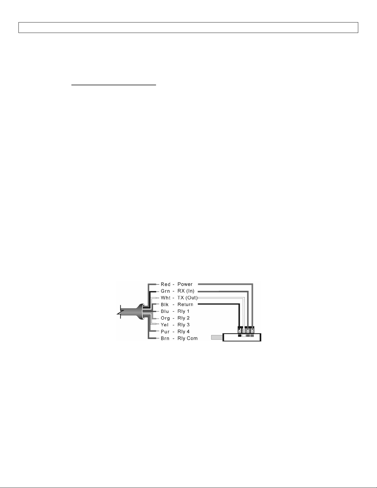
Connectthered,green,whiteandblackwiresfromsensorintothecorrectterminalsontheFob.Tightenthe
screwsontheterminalsandplugyourFobintotheUSB®portofyourcomputer.
Wiringidenticalforallseries–UseonlytheRed,Black,GreenandWhitewires.
Themaximumcabledistancebetweenthecomputerandultrasonicsensoris15’.Thisonlyapplieswhen
configuringthesensor.
s with LVCN414‐SW software through a USB® interface called a Fob.
‐SW
Oncetheultrasonic sensor isconfiguredand priortoinstallation,isolatethe whiteandgreenwiresfrom
activepowertopreventashortoftheconfigurationcircuit.
Note:When
therequiredpowertotheultrasonicsensor.
usingtheFob,donotaddVDCpower.TheFob,whenconnectedtothecomputer,willprovide
8
Page 9
LVCN414‐SWSOFTWARE StepSix
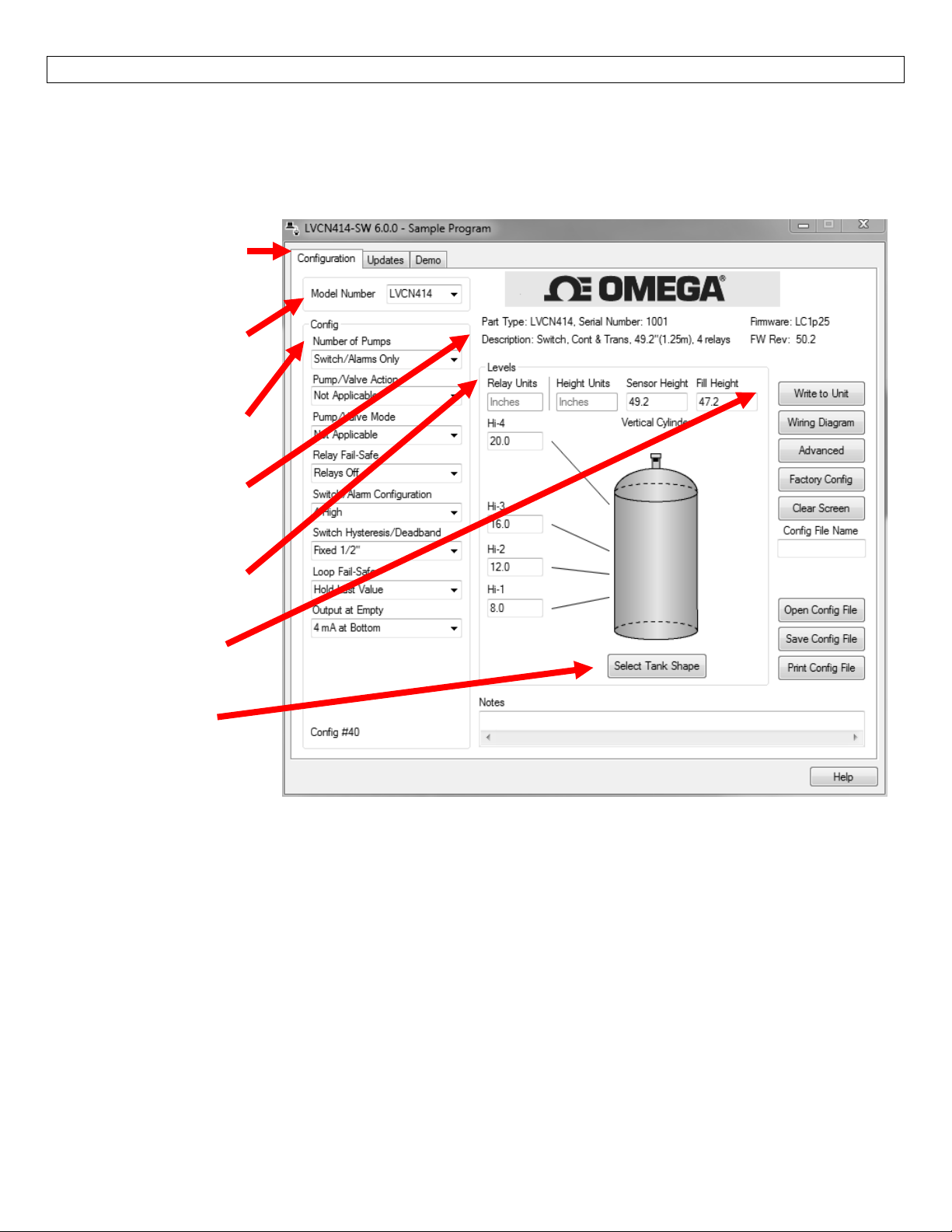
With the ultrasonic sensor connected toyourcomputer,opentheLVCN414‐SWsoftware by clicking on the
software’sicon.Followsteps1‐3toconfigurethetransmitter.Click“Help”inthelowerrighthandcornerand
openthehelp menuforadditionalinstructions.Ifyouneedadditional assistanceusingthesoftware,please
contactanOMEGAENGINEERINGApplicationsengineer.
TabsforConfiguration,
UpdatesandDemomode
ModelSelector
(SampleProgramOnly)
ConfigurationSelector
SensorDetails
LevelConfiguration
ActionButtons
TankSelector
AboveScreenCaptureisfortheLVCN414Series.
ConfiguringLVCN414,LVCN210&LVCN318SerieswithLVCN‐414‐SWSoftware
1. OutputConfiguration
a. Configurestherela
b. Setsfail‐safefortherelaysandthesensor’soutput(current,voltageorfrequency).
2. TankShapeSelection
a. Definestheshapeofthetankaswellasthedimensional informationforthetankwithrespect
tothesensor’slocationonthetank.
3. LevelConfiguration
a. Entersthedist
4. WritetoUnit
a. Uploadstheconfigurationintothesensor.
b. Providesacustomwiringdiagram.
ysintermsofpump/valveoperationsaswellashighorlowalarms.
ancevaluesfortheoperationalrangeofthesensor.
9
Page 10
SOFTWARE‐OUTPUTCONFIG.–LVCN414,LVCN210,LVCN318andLVCN414‐RSeriesonly StepSix
1.OutputConfiguration
Thissectioniswhere youselecttheapplication’s configurationsettings.Startfromthetop andworktothe
bottom,choosingtheselectionsthatareapplicabletoyourconfiguration.“NotApplicable”willautomatically
showwhenaselectiondoesn’tapplytoyourconfigurationsettings,and youmaymoveon.Allconfiguration
settingsmustbeselectedorhave“NotApplicable”beforeyoucancontinuetothenextstep.Note:Pressing
theClearScreenbuttonwillresettheconfigurationtableandallowaccesstoallofthefeatures.
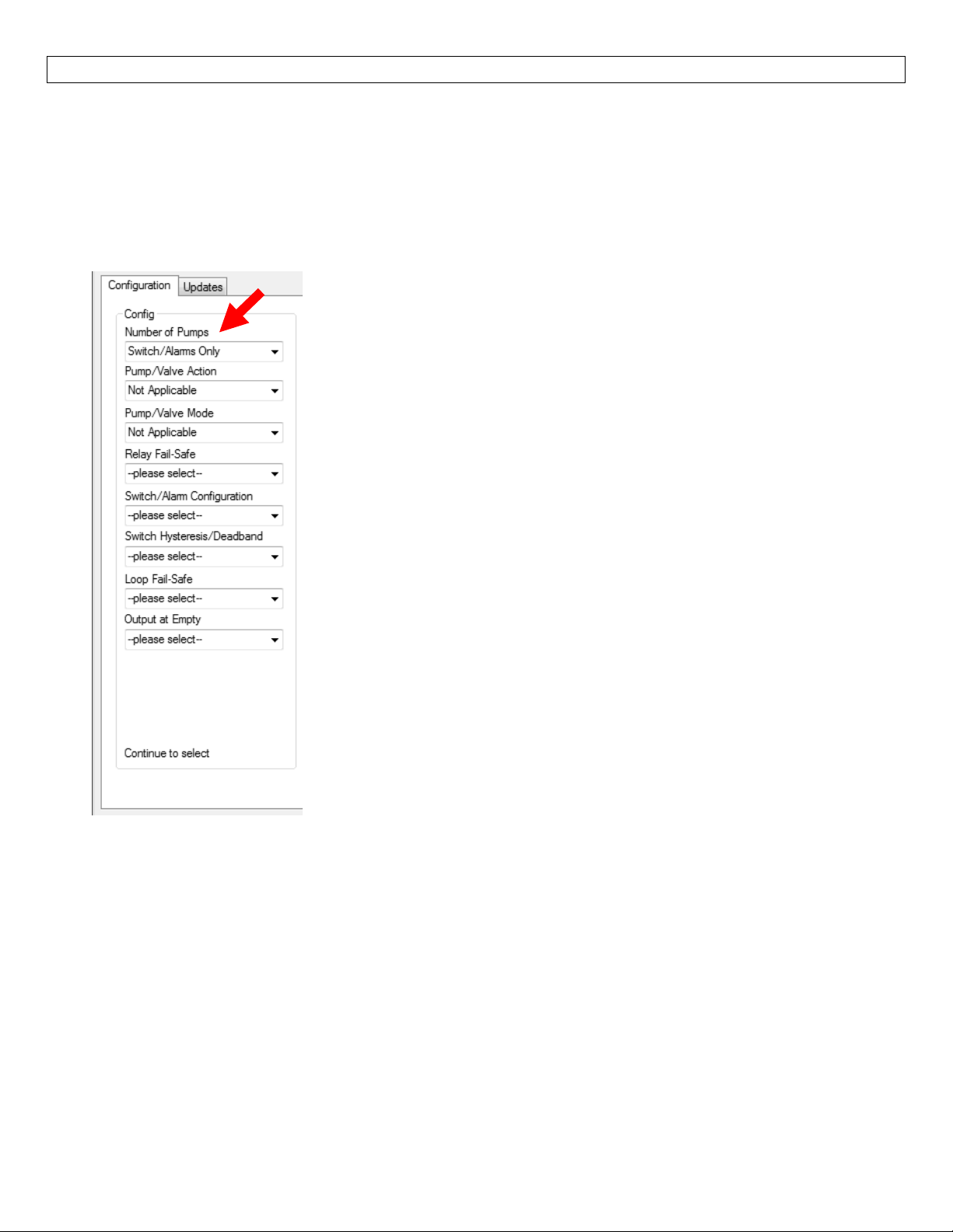
NumberofPumps
Thisfeatureallowsyoutoselectthenumberofpumpsorvalves used.
This is thesetting that activates thecontrol capabilities of upto two
relays.ControlrelaysareoftenreferredtoasLatchingrelays.
o Switch/Alarms Only – Therelays will be standardsingle point
relays(Highand/orLowalarms).Relaysarenon‐latching.
o 1‐ Pump/Valve – One relay will be configuredas a controlor
latchingrelay(relaywillhaveastartlevelandaseparatestop
level).Use this setting to control one pump or valve for
automaticfillingoremptyingofatank.
o 2‐Pumps/Valves – Two relays are configured as control or
latchingrelays.Eachrelaywillhavea unique start level and a
common stop level.Use thissettingto control two pumpsor
valvesforautomaticfillingoremptyingofatank.
o 4‐20mATransmitterOnly–Thissettingwilldisengageallofthe
relays.Use this function if you are not using any relays and
usingonlythe4‐20mAcurrentoutput.
Note:Rightclickonanymenuthatyoumayhavequestionsontoopenthehelpmenu.
Note:Toreset,presstheClearScreenbutton.
10
Page 11
SOFTWARE‐OUTPUTCONFIG.–LVCN414,LVCN210,LVCN318andLVCN414‐RSeriesonly StepSix
Pump/ValveAction
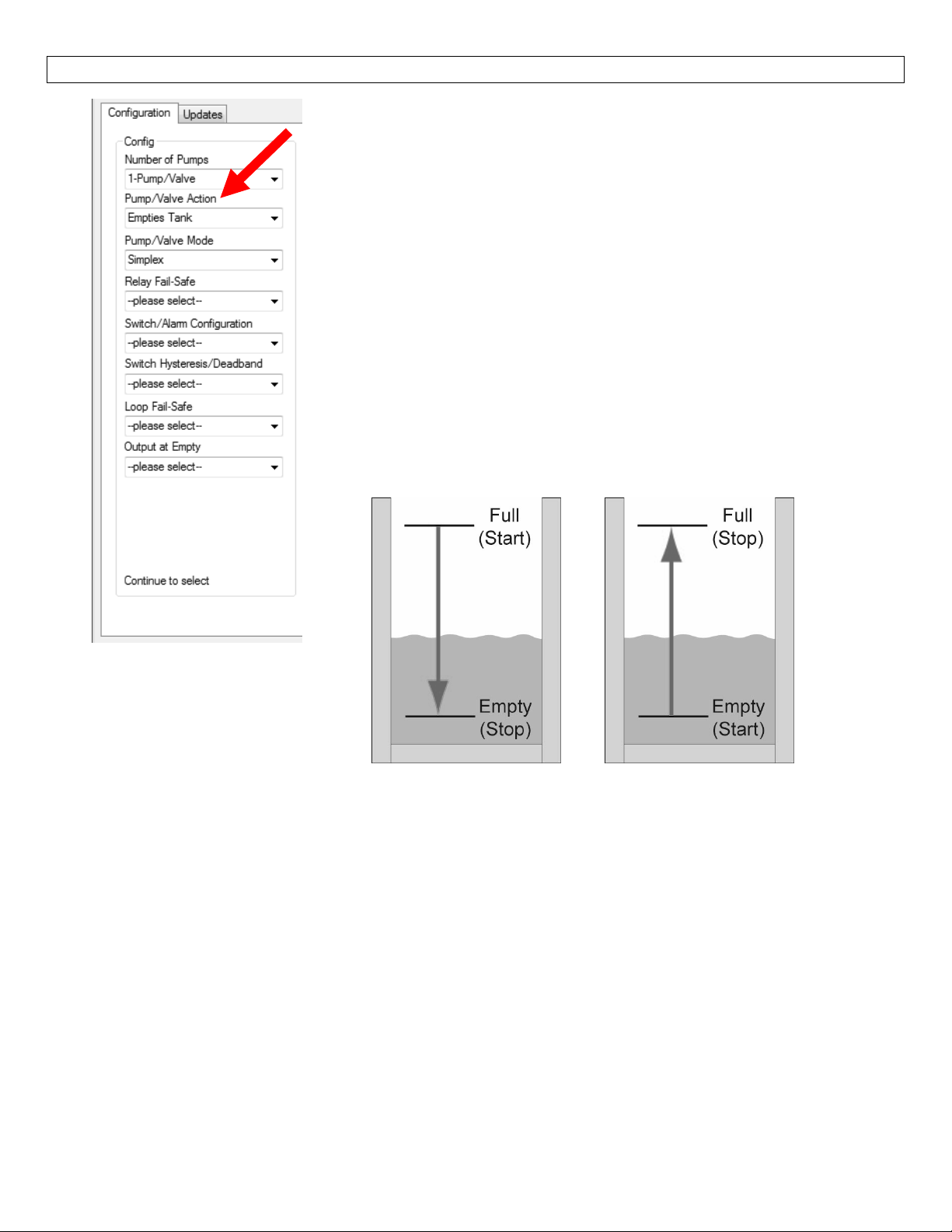
Thisfeatureallowsyoutoselectifthepumpsorvalveswillbeusedto
automatically fill or empty the tank.For 2‐Pump/Valve mode, both
devices must be the same(automatic fill or empty).You cannot set
onerelayforfillandtheotherforempty.
o EmptiesTank– Willsetrelay(s) toautomaticallyemptyatank.
StartlevelwillbeabovetheStoplevelforeachrelay.
o Fills Tank – Will set relay(s) to automatically filla tank.Start
levelwillbebelowtheStoplevelforeachrelay.
o Not Applicable – Appears when this function is not available
(such as when Switch/Alarms Only or 4‐20mA Transmitters
Onlyareselected).
EmptiesTank FillsTank
(AutoEmpty) (AutoFill)
Note:Rightclickonanymenuthatyoumayhavequestionsontoopenthehelpmenu.
Note:Toreset,presstheClearScreenbutton.
11
Page 12
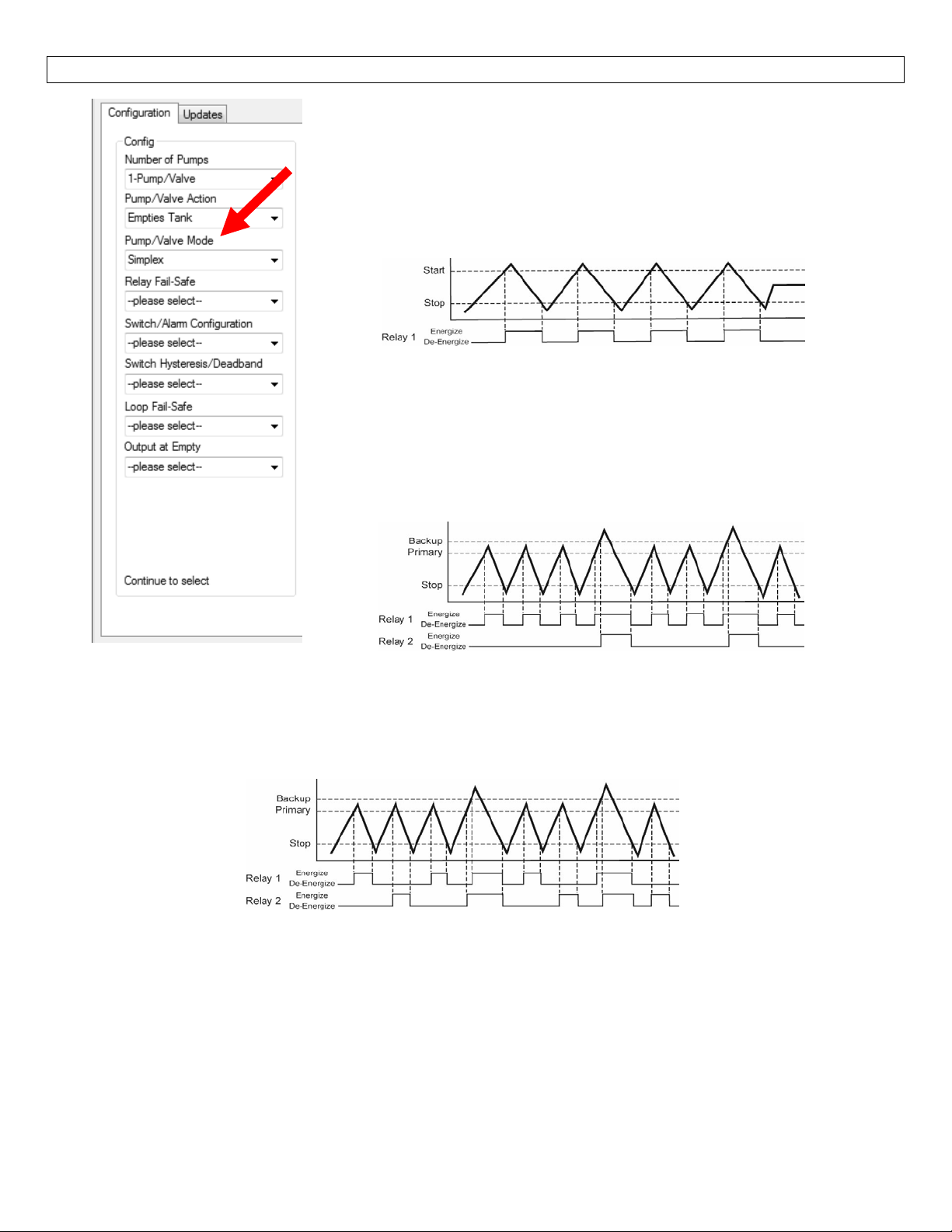
SOFTWARE‐OUTPUTCONFIG.–LVCN414,LVCN210,LVCN318andLVCN414‐RSeriesonly StepSix
Pump/ValveMode
This feature allows you to select the mode for a control or latching
relay.Pump/Valvemodeisnotactive for Switch/AlarmsOnlyor4‐20
mATransmitterOnly.
o Simplex–Allowsfortherelaytobeusedasanautomaticfillor
empty.This is the default and only configuration when 1‐
Pump/Valveisselected.
SimplexusedtoEmptyTank(example)
o Lead/Lag–Allowsforth
and a common stop level.The first relaywill be identified as
the lead relay andthesecondrelayas the lag.Each time the
lead level isreached, the firstrelay will always start.Th
relaywillonlystartwhenthelaglevelisreached.Allrelayswill
stopatthecommonofflevel.
Lead/LagusedtoEmptyTank(example)
o Duplex‐Allowsforthetworelaystohavetwodifferentstartlevels,acommonstop levelandwill
alternatetherelayswhenthefirststart level is reached.The two relayswillalternateeachtime
theleadlevelisreachedandtheremainingrelaywillstartwhenthelaglevelisreached.Allrelays
willstopatthecommonofflevel.
etworelaystohaveuniquestartlevels
e lag
DuplexusedtoEmptyTank(example)
o NotApplicab
4‐20mATransmittersOnlyareselected).
Note:Rightclickonanymenuthatyoumayhavequestionsontoopenthehelpmenu.
Note:Toreset,presstheClearScreenbutton.
le–Appearswhenthisfunctionisnotavailable(suchaswhenSwitch/AlarmsOnlyor
12
Page 13
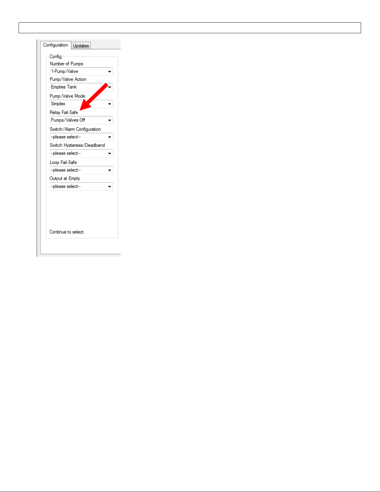
SOFTWARE‐OUTPUTCONFIG.–LVCN414,LVCN210,LVCN318andLVCN414‐RSeriesonly StepSix
RelayFail‐Safe
This feature allows you to select the fail‐safe state for the relays.
Whenthesensorregainssignal, theoutputcurrentwill revert backto
thecurrentlevelcondition.
o Relays Off ‐ The relays will revert to the OFFstate.Appears
whenSwitch/AlarmsOnlyisselected.
o Relays On ‐ The relays will revert to the ON state.Appears
whenSwitch/AlarmsOnlyisselected.
o Hold State‐Therelay(s) will remainin the samestate as the
lastechodetected.Whenthe sensorregainssignal,the relays
willreverttothelevelwhenthesignalwasregain.
o Pump/Valves Off ‐ The relays will revert to the OFF state.
Appearswhen1‐Pump/Valveor2‐Pumps/Valvesareselected.
o Pump/Valves On ‐ The relays will revert to the ON state.
Appearswhen1‐Pump/Valveor2‐Pumps/Valvesareselected.
o Not Applicable – Appears when this function is not available
(suchaswhenTransmittersOnlyareselected).
Note:Rightclickonanymenuthatyoumayhavequestionsontoopenthehelpmenu.
Note:Toreset,presstheClearScreenbutton.
13
Page 14
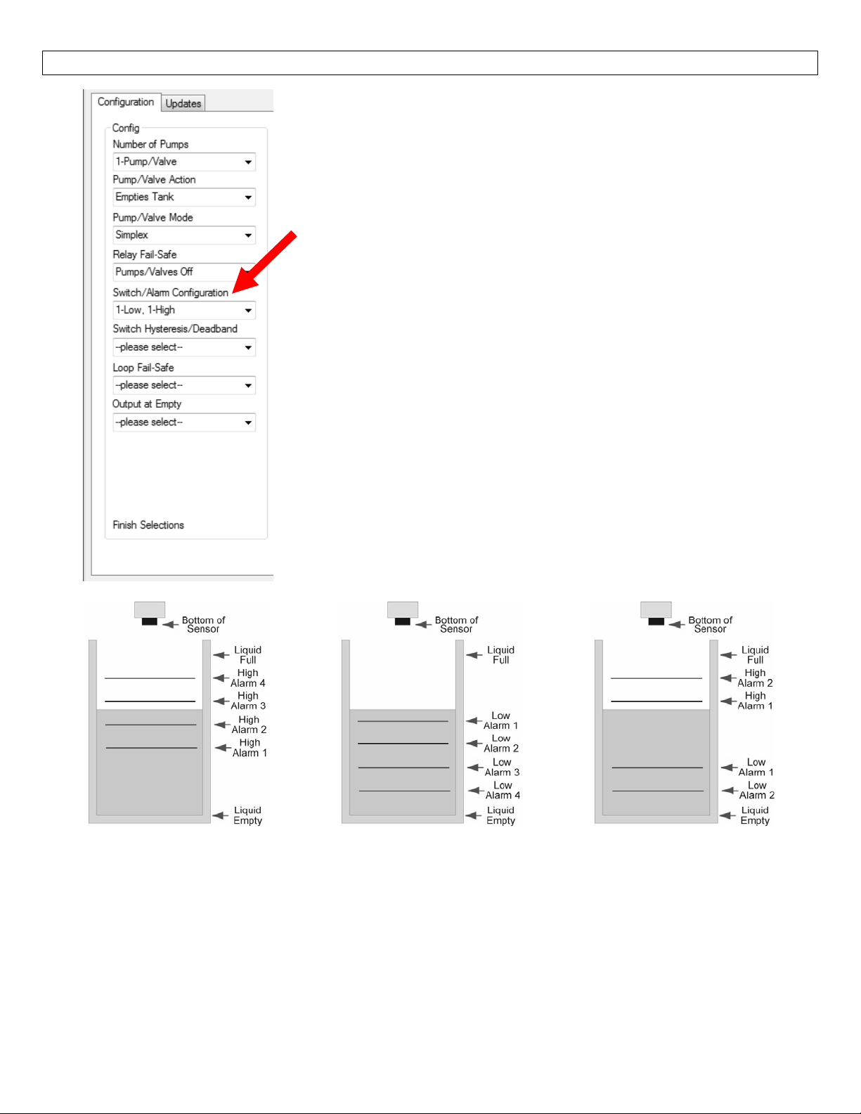
SOFTWARE‐OUTPUTCONFIG.–LVCN414,LVCN210,LVCN318andLVCN414‐RSeriesonly StepSix
Switch/AlarmConfiguration
This feature allows you to select the operation for the switches /
alarms(usedas ahighorlow alarm).Thissettingadjuststhenumber
ofavailablerelaysbasedupontheprevioussettings.
o NoAlarm–Turnsoffalloftheremainingrelays.
o High Alarm Options – Set from 1 to 4 High Alarms (1‐High, 2‐
High,3‐High,4‐High).
o Low Alarm Options – Set from 1 to 4 Low Alarms (1‐Low, 2‐
Low,3‐Low,4‐Low).
o Combination Alarms – Set a combination of High and Low
Alarms (1‐Low 1‐High, 1‐Low 2‐High, 2‐Low 1‐High, 2‐Low 2‐
High,1‐Low3‐High,3‐Low1‐High).
o Not Applicable – Appears when this function is not available
(suchaswhenTransmittersOnlyisselected).
HighAlarmOptions LowAlarmsOptions CombinationAlarms
(4High) (4Low) (2Highand2Low)
Note:Rightclickonanymenuthatyoumayhavequestionsontoopenthehelpmenu.
Note:Toreset,presstheClearScreenbutton.
14
Page 15
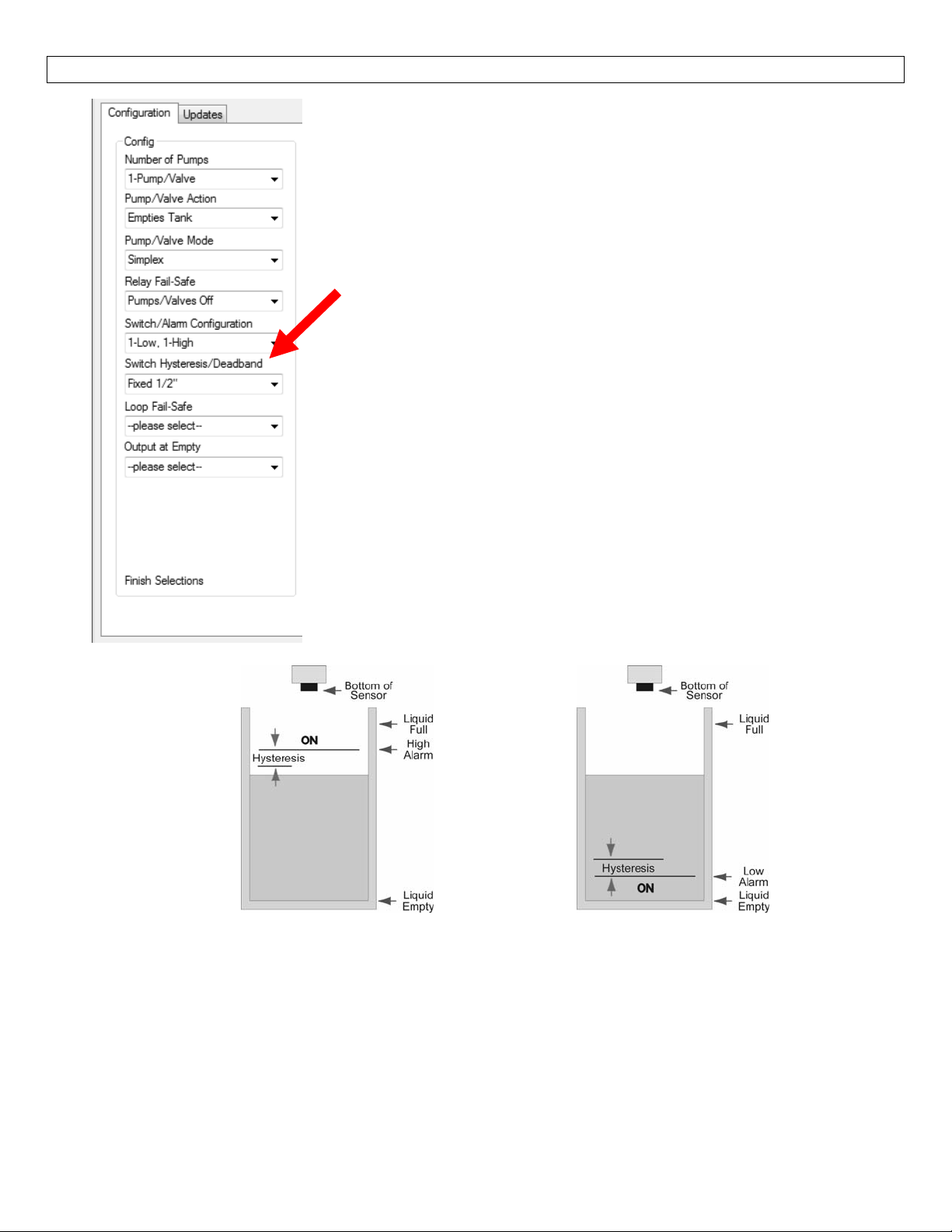
SOFTWARE‐OUTPUTCONFIG.–LVCN414,LVCN210,LVCN318andLVCN414‐RSeriesonly StepSix
SwitchHysteresis/Deadband
This feature allows you to select a hysteresis or dead band for the
remaininghighand/orlowalarms.
o OptionsforHysteresis/Deadband –NoHysteresis,¼”, ½”,1”,
2”,½cm,1cm,2cm,5cmorNotApplicable.
o High Alarms – Relay activates above set point.Relay will
deactivatewhenlevelgoesbelowthesetpointplusthevalueof
thehysteresis.
o Low Alarms – Relay activates below set point.Relay will
deactivatewhenlevelgoesabovethesetpointplusthevalue of
thehysteresis.
HighAlarmw/Hysteresis
Note:Rightclickonanymenuthatyoumayhavequestionsontoopenthehelpmenu.
Note:Toreset,presstheClearScreenbutton.
LowAlarmw/Hysteresis
15
Page 16
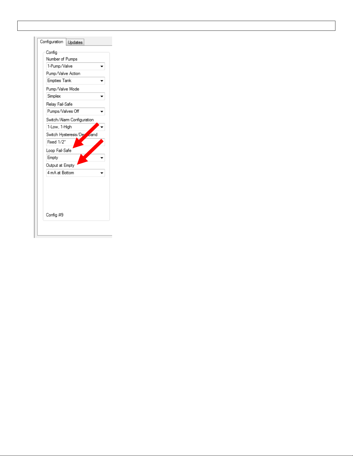
SOFTWARE‐OUTPUTCONFIG.–LVCN414,LVCN210,LVCN318andLVCN414‐RSeriesonly StepSix
LoopFail‐Safe‐(NotAvailablewithLVCN414‐Rseries)
This feature allows you to select the fail‐safe current output if the
sensor fails to detect a return signal. Whenthesensorregainssignal,
theoutputcurrentwillrevertbacktothecurrentlevelcondition.
o Hold Last Value‐Theoutput will remain in the samestateas
thelastecho detected.Example:Ifthe outputwas6.7mA just
prior to thelost signal, thedevice will continueto output 6.7
mA.Sensorwillindicatethelevelwhensignalwasregain.
o Empty‐ The output will revert to the current value for an
emptycondition.When4mAatBottomisselected,thesensor
willoutput4mAwhenafail‐safeconditionoccurs.If20mAat
Bottom is selected, thesensor will output 20mAwhen a fail‐
safeconditionoccurs.
o Full ‐ The output will revert to the current value for a full
condition.When 4 mA at Bottom isselected, the sensor will
output 20 mA when a fail‐safe condition occurs.If20 mA at
Bottomisselected,thesensorwilloutput4mAwhenafail‐safe
conditionoccurs.
o Overfill(21mA)‐Theoutputcurrentwillgoto21mAwhenthe
returnsignalislost.
o Overfill(22mA)‐Theoutputcurrentwillgoto22mAwhenthe
OutputatEmpty‐(NotAvailablewithLVCN414‐Rseries)
This feature allows youto select the orientation ofthe 4 to 20mAoutput (4 to 20mAor 20 to 4mA).
Choosewhichoutputsetting bestfitstheapplication.Typicalinstallationsare setwith4mA at Bottom.
Thiswillnotaffecttheperformanceofthesensor other than the output.The factory default is4mA at
bottom and 20mA attop. When connecting your sensor to a display, yo
settings.
o 4mAatBottom‐Theoutput current willbe4mAwhenthesensor measures anemptytankand
20mAwhenthesensormeasuresafulltank.
o 20mAatBottom‐Theoutputcurrentwillbe20mAwhenthesensormeasuresanemptytankand
4mAwhenthesensormeasuresafulltank.
Note:Right
Note:Toreset,presstheClearScreenbutton.
clickonanymenuthatyoumayhavequestionsontoopenthehelpmenu.
returnsignalislost.
u must account for your output
16
Page 17
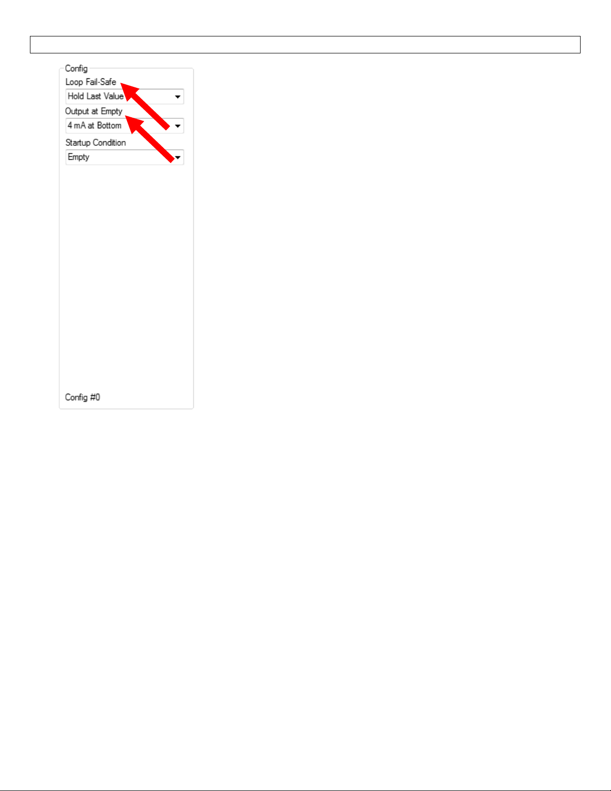
SOFTWARE‐OUTPUTCONFIGURATION–LVCN414‐ISeriesonly StepSix
LoopFail‐Safe
This feature allows you to select the fail‐safe current output if the
sensor fails to detect a return signal. Whenthesensorregainssignal,
theoutputcurrentwillrevertbacktothecurrentlevelcondition.
o Hold Last Value‐Theoutput will remain in the samestateas
thelastecho detected.Exampl
prior to thelost signal, thedevice will continueto output 6.7
mA.Sensorwillindicatethelevelwhensignalwasregain.
o Empty‐ The output will revert to the current value for an
emptycondition.When4mAatBottomisselected,thesensor
willoutput4mAwhenafail‐safeconditionoccurs.If20mAat
Bottom is selected, thesensor will output 20mAwhen a fail‐
safeconditionoccurs.
o Full ‐ The output will revert to the current value for a full
condition.When 4 mA at Bottom isselected, the sensor will
output 20
Bottomisselected,thesensorwilloutput4mAwhenafail‐safe
conditionoccurs.
mA when a fail‐safe condition occurs.If 20 mA at
e:Ifthe output was6.7mAjust
o Overfill(21mA)‐Theoutputcurrentwillgoto21mAwhenthe
returnsignalislost.
o Overfill(22mA)‐Theoutputcurrentwillgoto22mAwhenthe
returnsignalislost.
OutputatEmpty
This feature allows youto select the orientation ofthe 4 to 20mAoutput (4 to 20mAor 20 to 4mA).
Choosewhichoutputsetting bestfitstheapplication.Typicalinstallationsare setwith4mA at Bottom.
Thiswillnotaffecttheperformanceofthesensor other than the output.The factory default is4mA at
bottom and 20mA attop. When connecting your sensor to a display, you must account for your output
settings.
o 4mAatBottom‐Theoutput current willbe4mAwhenthesensor measures anemptytankand
20mAwhenthesensormeasuresafulltank.
o 20mAatBottom‐Theoutputcurrentwillbe20mAwhenthesensormeasuresanemptytankand
4mAwhenthesensormeasuresafulltank.
Note:Right
Note:Toreset,presstheClearScreenbutton.
clickonanymenuthatyoumayhavequestionsontoopenthehelpmenu.
17
Page 18
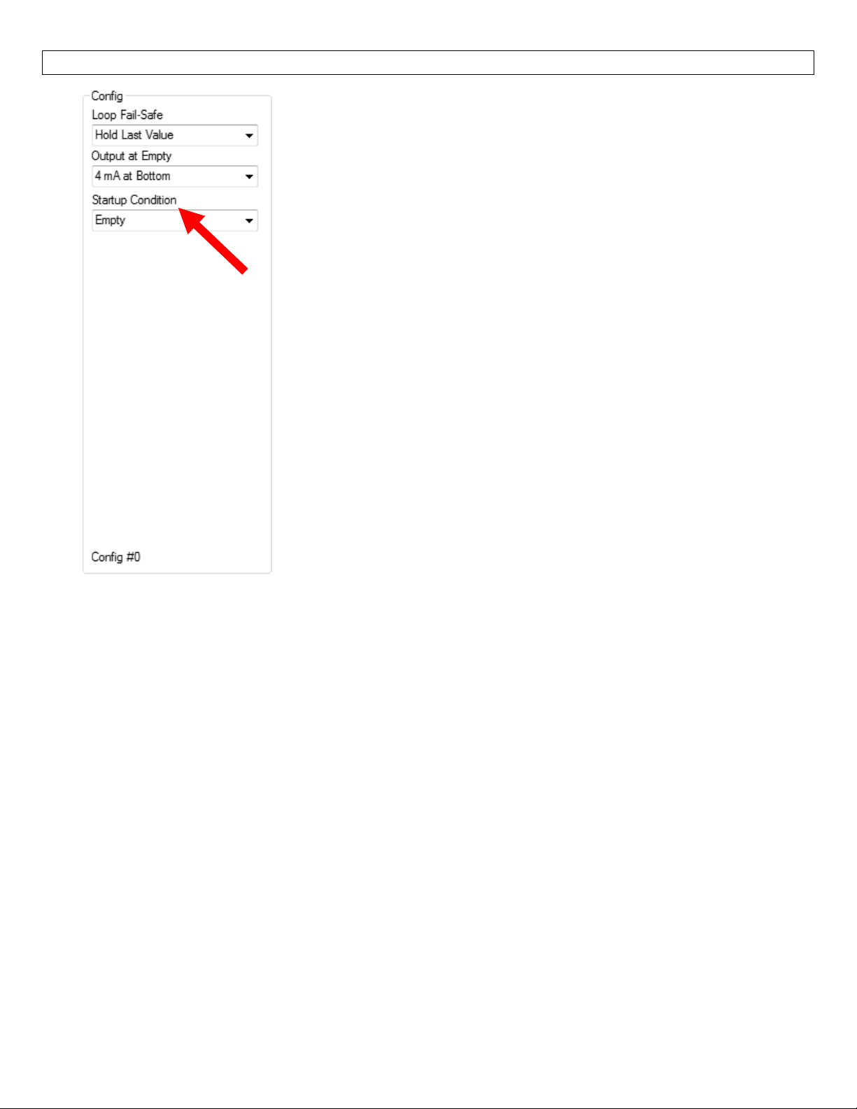
SOFTWARE‐OUTPUTCONFIGURATION–LVCN414‐ISeriesonly StepSix
StartupCondition
Thisfeatureallowsyoutoselectthestartupcurrentwhenpowerisfirst
appliedtothesensor.TheLVCN414‐Iwillconsumetheselectedpower
whileitisacquiringtheleveloftheliquid.Whenthecorrectlevelhas
beenidentified,theoutput will adjusttothecorrectoutput.Use this
feature to avoid false alarms with the controller when power isfirst
applied.
o Empty‐Thecurr
an empty condition.When 4 mA at Bottom is selected, the
sensorwilloutput 4mAwhile thesensorpowersup.If20mA
at Bottom is selected, the sensor willoutput20mAwhilethe
sensorpowe
o Mid Tank (12 mA) – The output will hold at 12 mA until the
correctlevelisread.
o Full ‐ The output will revert to the current value for a full
condition.When 4 mA at Bottom isselected, the sensor will
output20mAwhilethesensorpowersup.If20mAatBottom
isselected,thesensorwilloutput4mAwhilethesensorpowers
Note:Rightclickonanymenuthatyoumayhavequestionsontoopenthehelpmenu.
up.
o Overfill(22mA)‐Theoutput currentwillgo to22mAwhile the
sensorpowersup.
entoutputwill revert tothecurrentvaluefor
rsup.
Note:Toreset,presstheClearScreenbutton.
18
Page 19
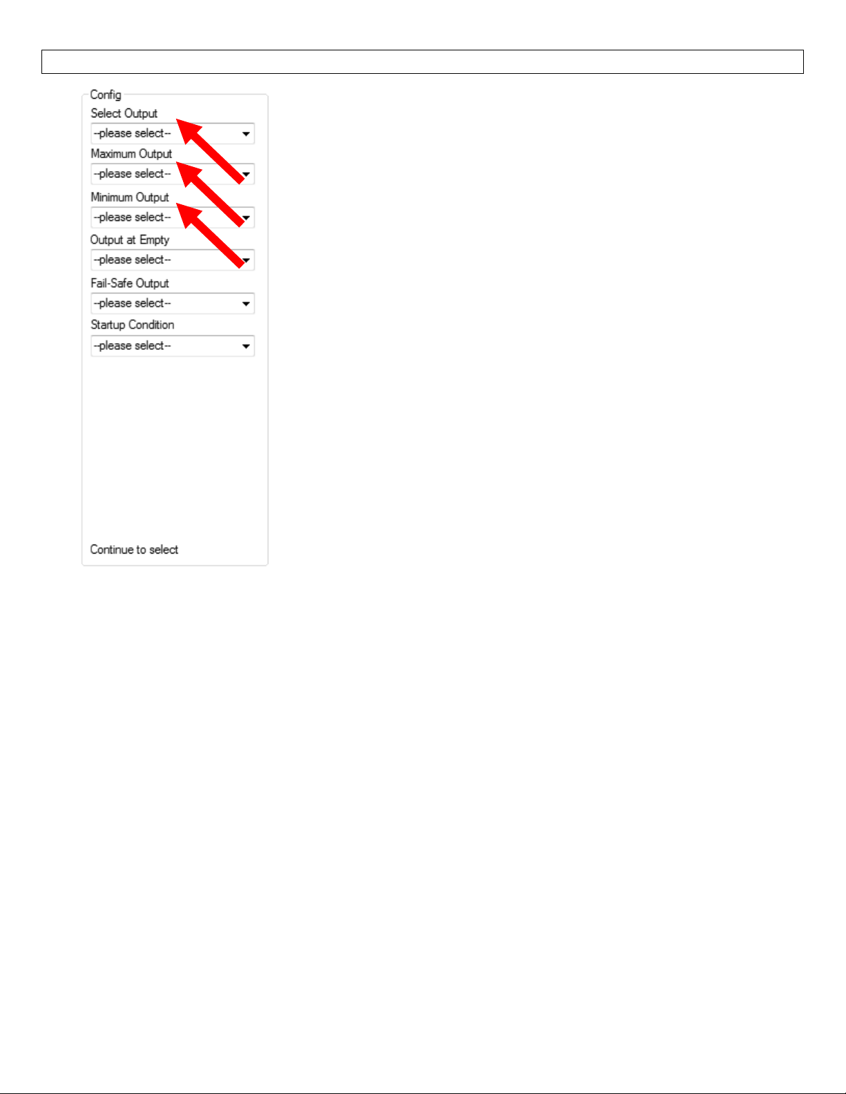
SOFTWARE‐OUTPUTCONFIGURATION–LVCN414‐VSeriesonly StepSix
SelectOutput
ThisfeaturesetstheoutputfortheLVCN414‐Vseries.Theoutputcan
eitherbeavoltageoutputorafrequencyoutput.
o Voltage – Select this option foravoltage output.You will be
abletoselectvoltagescaleof0‐2.5V,0‐3.3V,0‐5Vor0‐10V.
o Frequency – Select this option for a frequency/pulse output.
Theoutputwillbefixedfrom976to2000Hz.
MaximumOutput
This sets the maximum output for the LVCN414‐V series.If Voltage
was selected above, then the maximum value will be in Volts.If
Frequencyisselected,thenthemaximumvaluewillbeinHertz.
o Voltage–Choosefrom:2.5Volts,3.3Volts,5Voltsor10Volts.
o Frequency–Thisvalueisfixedat2000Hz.
MinimumOutput
ThissetstheminimumoutputfortheLVCN414‐Vseries.IfVoltagewas
selectedabove,thentheminimumvaluewillbeinVolts.IfFrequency
isselected,thentheminimumvaluewillbeinHertz.
o Voltage–Choosefrom:0.25Volts,0.5Volts,0.833Volts,1Volt
or2Volts.
o Frequency–Thisvalueisfixedat976Hz.
Note:Rightclickonanymenuthatyoumayhavequestionsontoopenthehelpmenu.
Note:Toreset,presstheClearScreenbutton.
19
Page 20
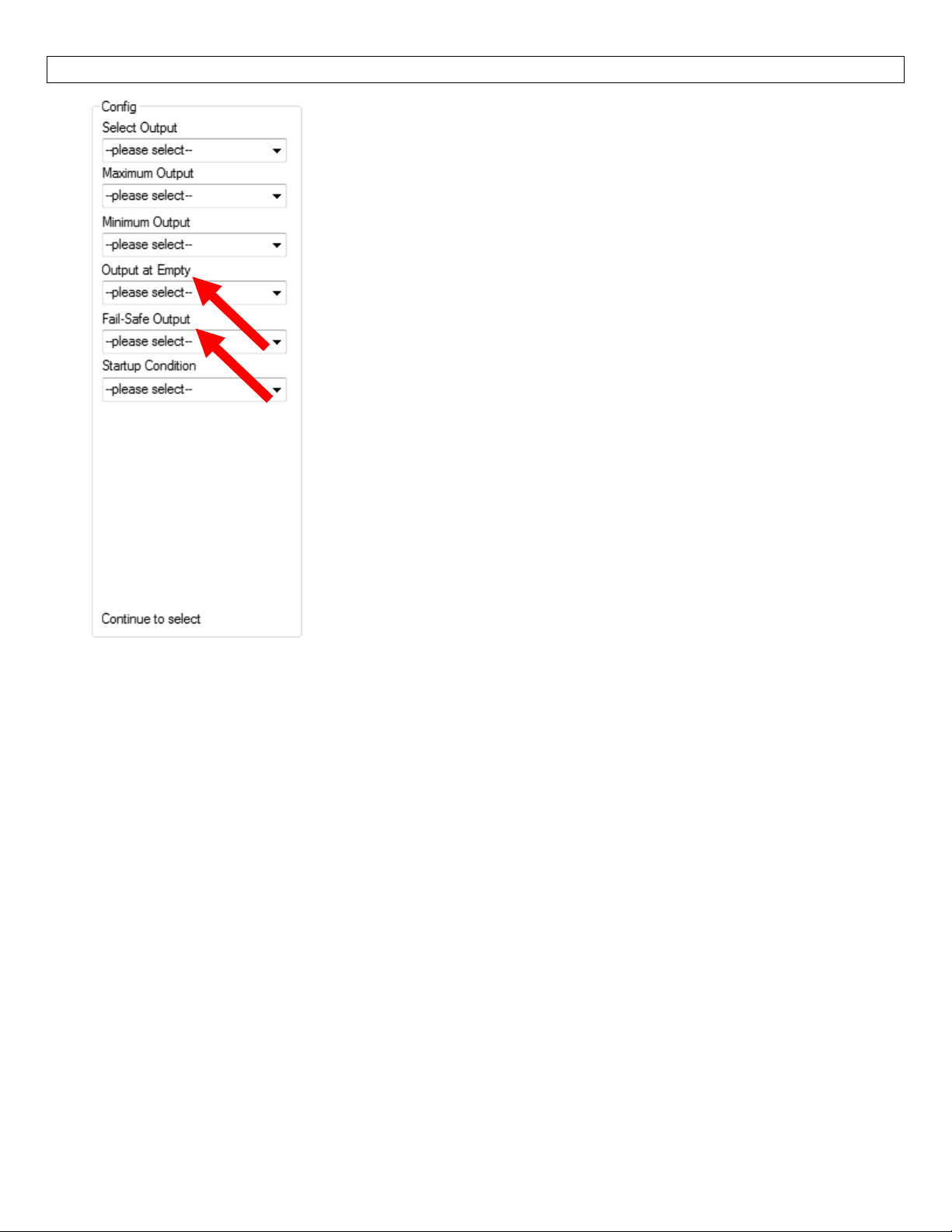
SOFTWARE‐OUTPUTCONFIGURATION–LVCN414‐VSeriesonly StepSix
OutputatEmpty
This feature allows you to select the orientation of the voltage or
frequencyoutput(ex.Empty=1voltandfull=10voltsvs.empty=10
volts and full = 1 volt).Choose which output setting best fits the
application.Typical installations are set with MinimumOutput.This
will not affectthe performance ofthe sensor otherthan the output.
When connecting your sensor to adisplay, youmustaccountfor your
outputsettings.
Minimum Output ‐ The output current will be the smallest
o
value.If reading in Voltage,thiswill be the minimumoutput
voltage.IfreadinginFrequency,thiswillbe976Hz.
o Maximum Output ‐ The output current will be the largest
value.Ifreadingin Voltage, this will be the max
voltage.IfreadinginFrequency,thiswillbe2000Hz.
Fail‐SafeOutput
Thisfeatureallows youtoselectthe fail‐safeoutputifthe sensorfails
to detect a returnsignal. When the sensorregainssignal, the output
currentwillrevertbacktothecurrentlevelcondition.
imum output
o Hold Last Value‐Theoutput will remain in the samestateas
o Empty‐The output will revert to the current value for an empty condition.When Minimum
Output isselected,thesensor will output the lowestvoltageorfrequencyvaluewhenafail‐safe
condition occurs.If Maximum Output is selected, thesensor will outputthe highest voltage or
frequencyvaluewhenafail‐safeconditionoccurs.
o Full ‐ The output will reverttothecurrentvaluefor a full condition.When MinimumOutputis
selected,thesensorwill output the highest
occurs.If Maximum Output is selected, the sensor will output thelowest voltage orfrequency
valuewhenafail‐safeconditionoccurs.
Note:Rightclickonanymenuthatyoumayhavequestionsontoopenthehelpmenu.
Note:Toreset,presstheClear
Screenbutton.
thelastechodetected.Example:Iftheoutputwas6.7voltsjust
prior to thelost signal, thedevice will continueto output 6.7
volts.Sensorwillindicatethelevelwhensignalwasregain.
voltageorfrequencyvalue when afail‐safecondition
20
Page 21
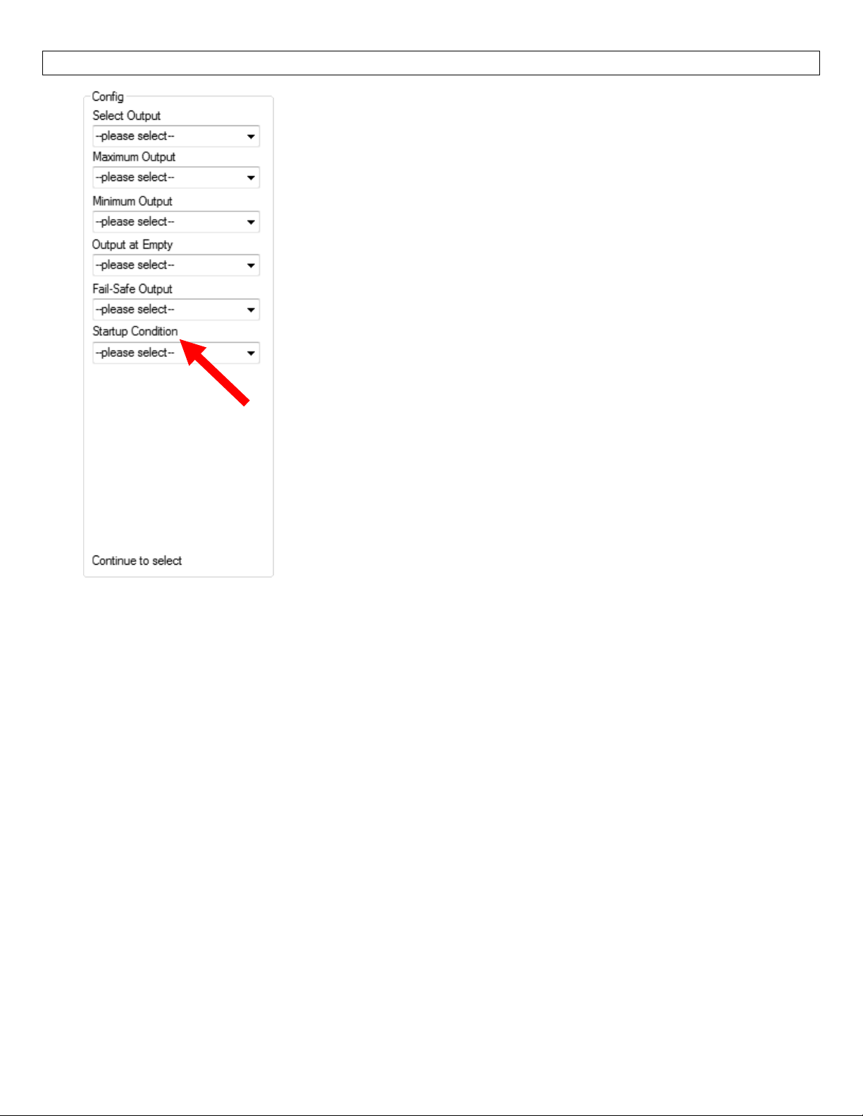
SOFTWARE‐OUTPUTCONFIGURATION–LVCN414‐VSeriesonly StepSix
StartupCondition
Thisfeatureallowsyoutoselectthestartupcurrentwhenpowerisfirst
applied to the sensor.The LVCN414‐V will consume the selected
power while itis acquiring thelevel of theliquid.When the correct
levelhasbeenidentified, the output willadjusttothecorrectoutput.
Usethisfeaturetoavoidfalsealarmswith
firstapplied.
o Empty‐ The output will revert to the current value for an
empty condition.When Minimum Output is selected, the
sensor will outputthe lowest voltageor frequency value until
thetruelevelis acquired.IfMaximumOutputis selected,
sensorwilloutputthehighestvoltageor frequency value until
thetruelevelisacquired.
o Mid Tank – The output will hold at the mid level of the
MinimumandMaximumOutputuntilthecorrectlevelisread.
thecontrollerwhenpoweris
the
o Full‐The output will revert to the current value for a full
condition.WhenMinimum Output isselected,thesensorwill
output the highest voltage or frequency value until the true
level is acquired.If Maximum Output is selected, the sensor
Note:Rightclickonanymenuthatyoumayhavequestionsontoopenthehelpmenu.
Note:Toreset,presstheClearScreenbutton.
willoutputthelowestvoltageorfrequencyvalueuntilthetrue
levelisacquired.
21
Page 22
SOFTWARE‐TANKSHAPESELECTION StepSeven
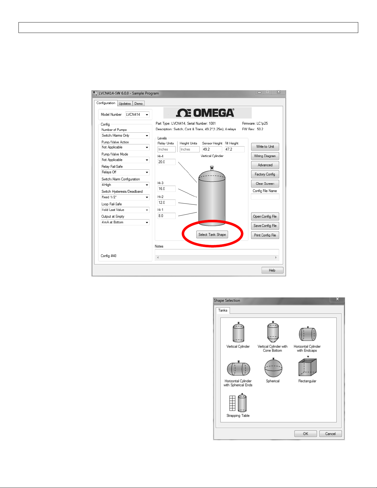
2.TankShapeSelection
The sensor may be configured in volumetric units (Gallons or Liters) or Distance (Height of Liquid) units
(inches,cm,feetor meters).TheLVCN‐414‐SWsoftwarewilldefault inDistance(HeightofLiquid) withunits
of Inches.To change the unitsortochange from Distance to Volume,presstheSelectTank Shape button
locatednearthecenterofthewindow.
ShapeSelectionWindow:ThiswindowwillshowsthedifferenttankshapeoptionsavailableinWebCal™.
VerticalCylindrical
VerticalCylindricalwithConeBottom
HorizontalCylindricalwithEndcaps
HorizontalCylindricalwithSphericalEnds
Spherical
Rectangular
Strapping Table –Use this feature formanual entry
ofmeasuredtankdistancesandvolumes.
Select any of the above tank shapes and press OK to
confirm.
22
Page 23
SOFTWARE‐TANKSHAPESELECTION StepSeven
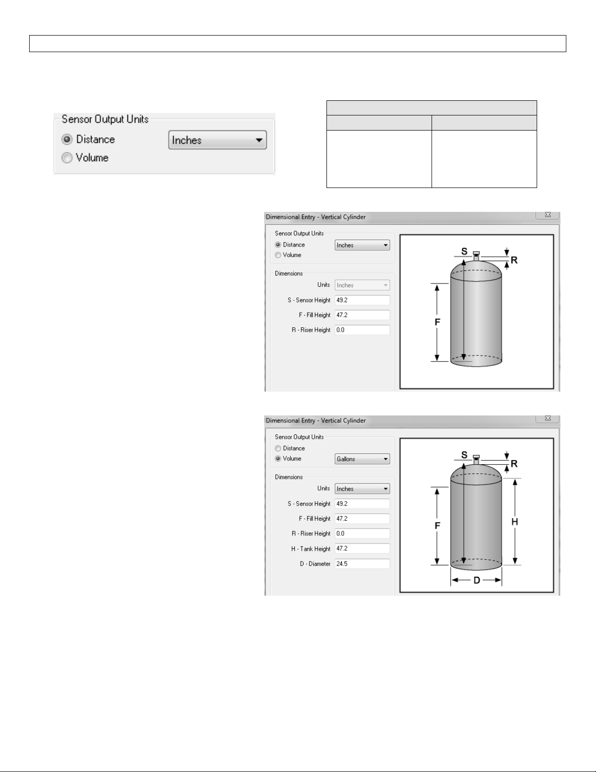
Dimensional Entry – Vertical Cylindrical Example:Choose the Sensor Output UnitsasDistanceorVolume.
AfterchoosingtheSensorOutputUnits,selecttheunitsofmeasurementinthepulldowntotheleft.
UnitsofMeasurement
Distance Volume
Inches
Cm
Feet
Meters
Gallons
Liters
Distance–SensorOutputUnits:
Enterthedimensionsofthetank.Youmust
enterdatainallfieldsshown.
SensorHeight:Distancefrom thebottomof
thetanktothebottomofthetransducer.
FillHeight:Distancefromthebottomofthe
tanktothemaximumliquidheight.
RiserHeight:Distancethesensorisrecessed
withinariser,measuredfromthe bottom of
thesensortotheinsideofthetank.
Volume–SensorOutputUnits:
Enterthedimensionsofthetank.Youmust
enterdatainallfieldsshown.
SensorHeight:Distancefrom thebottomof
thetanktothebottomofthetransducer.
FillHeight:Distancefromthebottomofthe
tanktothemaximumliquidheight.
RiserHeight:Distancethesensorisrecessed
withinariser,measuredfromthe bottom of
thesensortotheinsideofthetank.
Tank Height:Distance from the bottom of
thetanktothetopofthestraightsidewall.
Diameter:Distance of the inside tank
diameter.
23
Page 24
SOFTWARE‐TANKSHAPESELECTION StepSeven
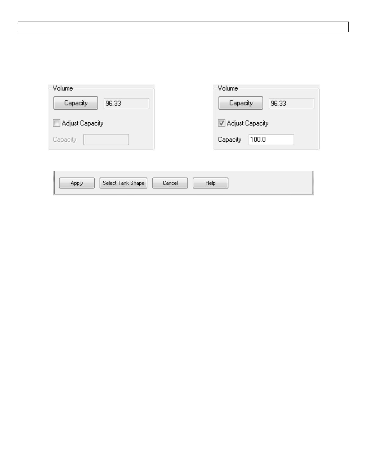
Volume – Tank Capacity:After entering the dimensions, presstheCapacitybuttontoshow the Calculated
Capacityofthe tank.If the CalculatedCapacityisslightly different than the expectedcapacity,clickonthe
AdjustCapacityboxandentertheexpectedcapacityofthetank.IftheAdjustedCapacityismorethan10%of
theCalculatedCapacity,recheckthedimensionsinformationenteredabove.
Whenalldimensionsareentered,presstheApplybuttontoreturntothepreviousConfigurationwindow.
Apply–TransfersthedimensionstotheoriginalConfigurationwindow.
Tanks–ReturnstothepreviousShapeSelectionwindow.
Cancel–ReturnstotheConfigurationwindowwithoutsavinganyinformation.
Help–JumpstotheHelpmenu.
24
Page 25
SOFTWARE‐TANKSHAPESELECTION StepSeven
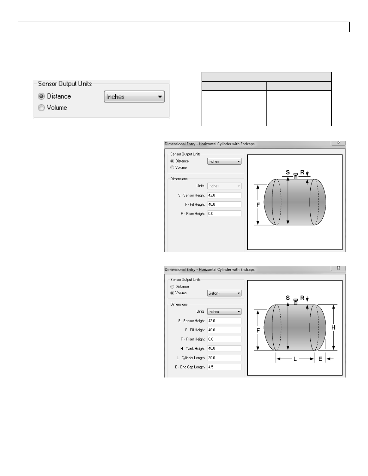
Dimensional Entry – Horizontal Cylindrical with Endcaps Example:Choose the Sensor Output Units as
Distance or Volume.After choosing the Sensor Output Units, select theunits of measurement in thepull
downtotheleft.
UnitsofMeasurement
Distance Volume
Inches
Cm
Feet
Meters
Gallons
Liters
Distance–SensorOutputUnits:
Enter the dimensions of the tank.You must
enterdatainallfieldsshown.
SensorHeight:Distancefromthebottomof
thetanktothebottomofthetransducer.
FillHeight:Distancefrom thebottomofthe
tanktothemaximumliquidheight.
RiserHeight:Distancethesensorisrecessed
withina riser, measured from the bottom of
thesensortotheinsideofthetank.
Volume–SensorOutputUnits:
Enter the dimensions of the tank.You must
enterdatainallfieldsshown.
SensorHeight:Distancefromthebottomof
thetanktothebottomofthetransducer.
FillHeight:Distancefrom thebottomofthe
tanktothemaximumliquidheight.
RiserHeight:Distancethesensorisrecessed
withina riser, measur
ed from the bottom of
thesensortotheinsideofthetank.
TankHeight:Distancefromthebottomofthetanktothetopofthestraightsidewall.
CylinderLength:
Distanceofthestraightlengthofthetank.
EndCapLength:Distanceofoneendcap.Bothendcapswillbeusedinthevolumecalculation.
25
Page 26
SOFTWARE‐TANKSHAPESELECTION StepSeven
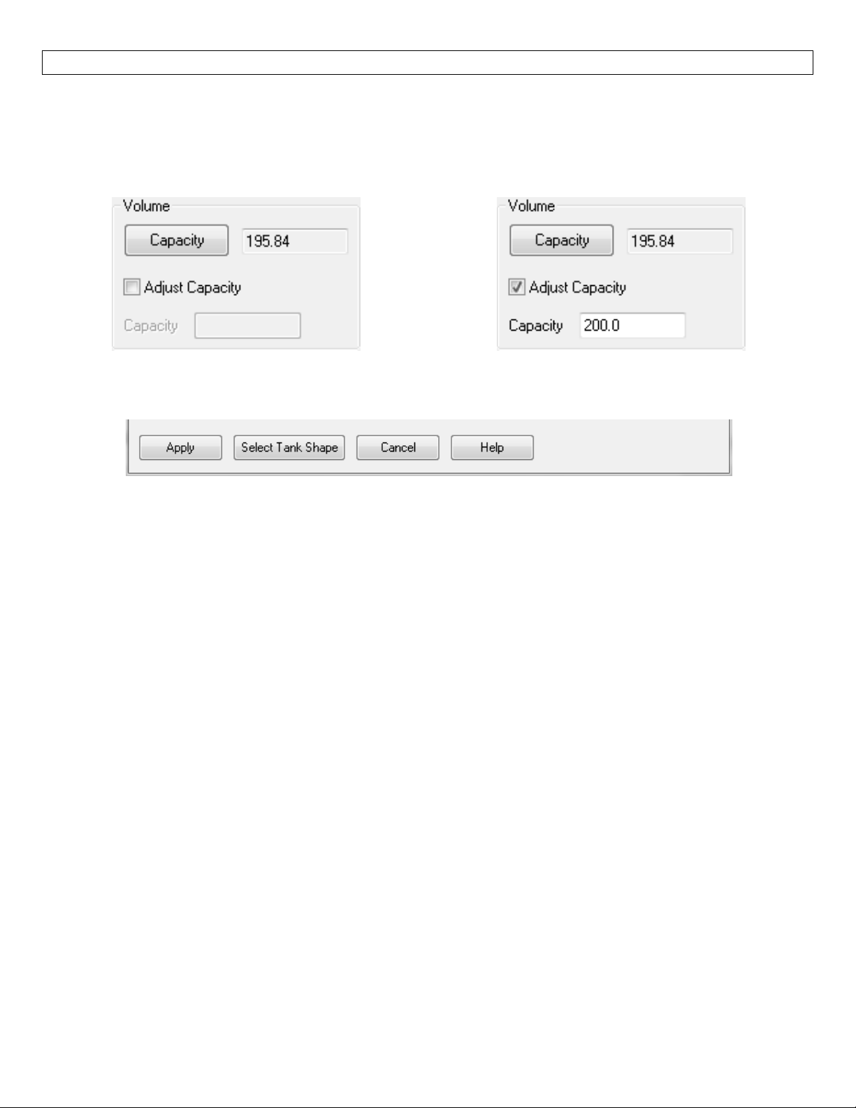
Volume – Tank Capacity:Upon entering thedimensions, presstheCapacitybuttontoshow the Calculated
Capacityofthe tank.If the CalculatedCapacityisslightly different than the expectedcapacity,clickonthe
AdjustCapacityboxandentertheexpectedcapacityofthetank.IftheAdjustedCapacityismorethan10%of
theCalculatedCapacity,recheckthedimensionsenteredabove.
Whenalldimensionsareenterediscompleted,presstheApplybuttontoreturntothepreviousConfiguration
window.
Apply–TransfersthedimensionsbacktotheoriginalConfigurationwindow.
Tanks–ReturnstothepreviousShapeSelectionwindow.
Cancel–ReturnstotheConfigurationwindowwithoutsavinganyinformation.
Help–JumpstotheHelpmenu.
26
Page 27
SOFTWARE–LEVELCONFIGURATION StepSeven
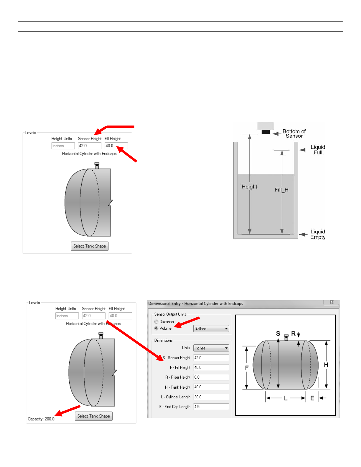
3.LevelConfigurations
Thissectioniswhereyouenterapplicationmeasurementvalues.Thisappliestoallversionsoftheultrasonic
sensor.YoumustentertheSensorHeightandFillHeightvalues.
FortheLVCN414‐I,LVCN414,LVCN210andLVCN318series, the Sensor Height andFill Heightvalues
determinetheoperationalrangeforthe4‐20mAoutput.
FortheLVCN414‐Vseries,the Sensor HeightandFill Heightvaluesdeterminetheoperationalrange
forthevoltageorfrequencyoutput.
SensorconfiguredinVolume
IfVolumeisselectedfortheSensorOutputUnits,thentheSensor Height and Fill Height values cannot be
changedonthispage.TheymustbeadjustedontheDimensionalEntryPage.Note:theCapacityofthetank
willappearinthelowerleftcornerwhenVolumeisselectedunderSensorOutputUnits.
Sensor Height: Distance from
thebottomofthe tanktothe
bottomofthetransducer.
Fill Height: Distance from the
bottom of the tank to the
maximumliquidheight.
27
Page 28
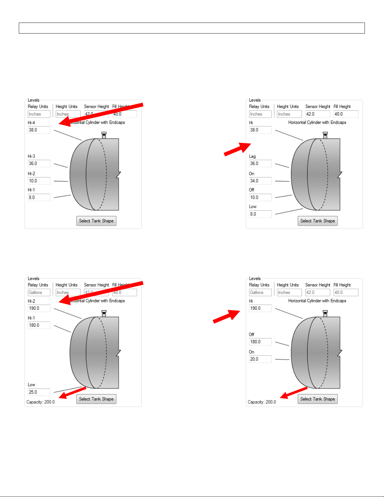
SOFTWARE–LEVELCONFIGURATION StepSeven
RelayValues:(LVCN414,LVCN210,LVCN318andLVCN414‐Rseriesonly)
Thissectioniswhereyouentertheoperationalvaluesforrelays.Youmustentervalueswithinallofthefields
shown.Thevaluefieldsshownarebasedupontheconfigurationofthesensor.Allvaluesmustbeintheunits
ofoperationselectedaboveandare baseduponunits ofliquid.Allrelayvalues mustbegreater
Empty(0)andlessthanLiquidFull(FillHeight).
Example: This sample shows
4 High Level Alarms.As the
level increases from the
bottom –up, each alarm will
activate.
Example: This sample shows
a2‐PumpLead/Lagoperation
with a High and Low alarm
The pumps will automatically
empty the tank and the
alarmswillactivateifthelevel
getstoohighorlow.
.
thanLiquid
SensorconfiguredinVolume
IfVolumeisselectedfortheSensorOutputUnits,thentherelayvaluesmustbeenteredintheunitsselected
(GallonsorLiters)fromtheDimensional EntryPage.Note:the Capacityofthe tankwillappear inthelower
leftcornerwhenVolumeisselectedunderSensorOutputUnits.
Example: This sample shows
2 High Level & 1 Low Level
Alarms.The values are in
unitsofGallons.
Example: This sample shows
a1‐Pumpfilloperationwitha
High alarm.The pump/valve
willautomaticallyfillthe tank
andthealarmswill activateif
thelevelgetstoohigh.Again,
the values for the relays are
inunitsofGallons.
28
Page 29
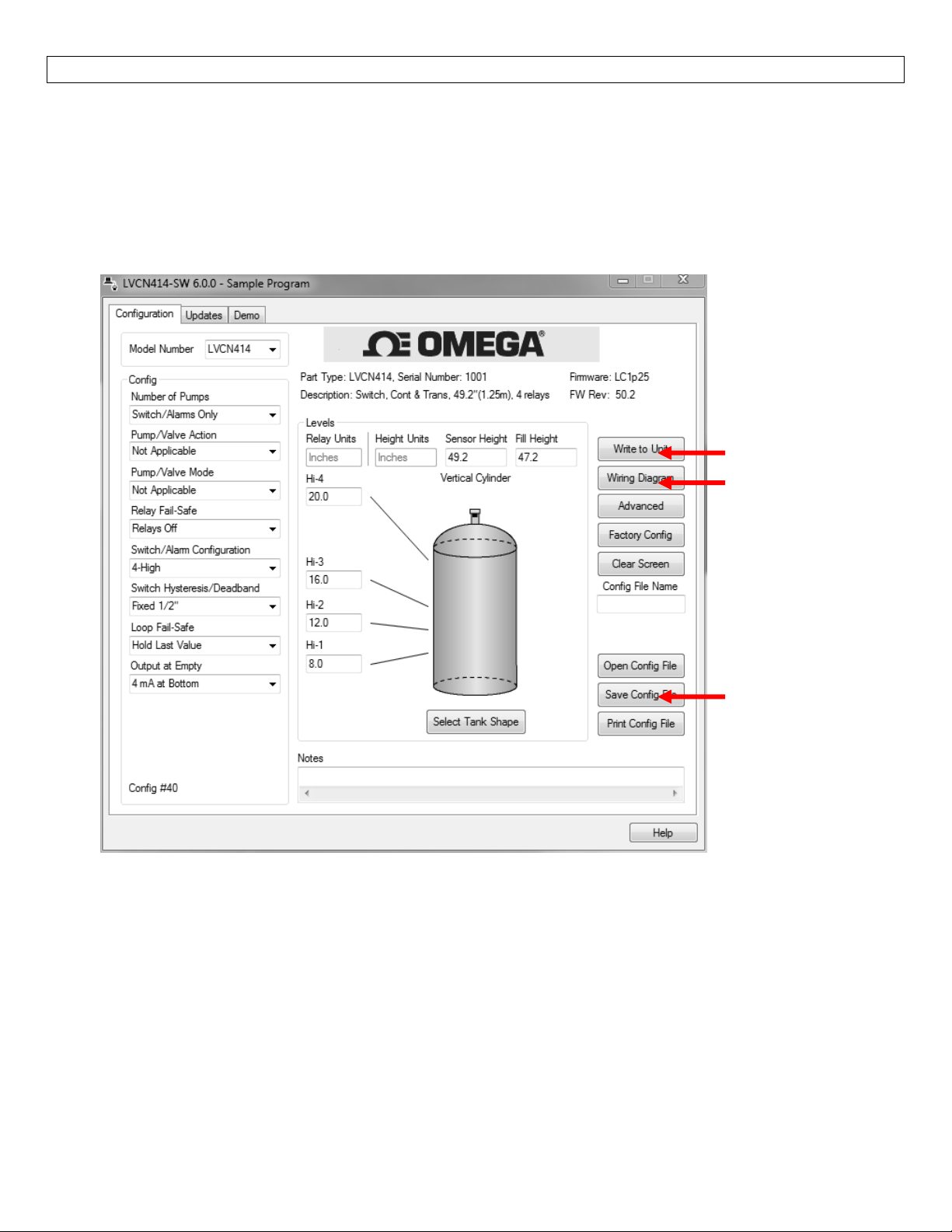
SOFTWARE‐WRITETOUNIT StepEight
4.WritetoUnit
Afteryouhaveenteredconfiguration,tankshapeinformationandlevelconfigurat ions, click“WritetoUnit”
toloadtheconfigurationinto the memory of thesensor.When completed,thisconfiguration will remain
insidethesensor’s memory and will not change unless the sensor is connected to LVCN‐414‐SWsoftware
andanewconfigurationiswrittentothe sen sor. Loss of power will not changeorlosetheconfiguration
withinsensormemory.
WritetoUnit
Wiringdiagram
SaveConfigFile
Next,usethefilemanagementfeaturestosaveyourconfigurationbyclicking“SaveConfigFile”and
wiringdiagrambyclicking“WiringDiagram.”
“SaveConfigFile”will save this configurationasatextfile which canbeloadedbackinto the LVCN‐414‐SW
softwarebypressingthe“OpenConfigFile”button.Itisgoodpracticetosavetheconfigurationfileforeach
different co
applications,thenuseofasingleconfigurationfileisrecommended.
nfiguration with a unique name for easy identification.If using multiple sensors in identical
printyour
“WiringDiagram”willdisplayaPDFfileshowingtheuniquewiringforthespecificconfigurationcreated.The
PDFcanbeprintedorEmailed.Itisgoodpracticetosavethewiringdiagramasabackup.
29
Page 30
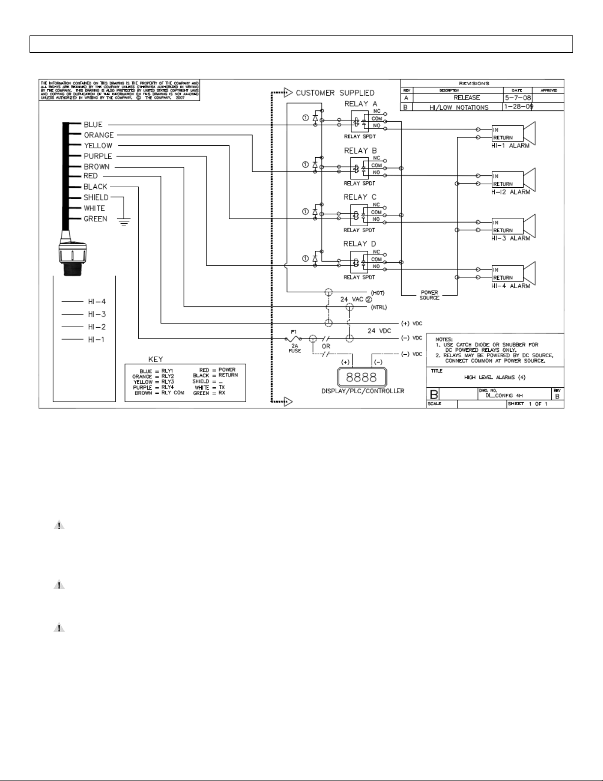
WIRING StepNine
WiringDiagram‐Sample
Diagramwillchangebasedupontheconfigurationofthesensor,
usetheLVCN414‐SWsoftwaretoviewappropriatewiringdiagram.
Wiring:Oncetheultrasonicsensorhasbeeninstalled,followtheWiringDiagramprovidedbythesoftware.A
typicalwiringdiagramisshownabove.OMEGAENGINEERINGrecommendsusingaqualifiedlicensed
electriciantowirethesensorandyourapplication’scomponents.
ConfigureyourultrasonicsensorwiththeLVCN414‐SWsoftwareandusethewiringdiagrambuttonto
viewtheappropriatediagram.Eachconfigurationwillhaveitsownuniquediagram.Thediagram
aboveisonlyasampleandshouldnotbeusedasawiringdiagram.
Alwaysusestepperrelaysbetweenthesensorandexternalloads.ForDCcircuitsuseacatchdiode
suchas1N4148,shownontheWiringdiagramshownabove.
Onceconfigured,isolatethewhiteandgreenwiresfromactivepowertopreventashortofthe
configurationcircuit.
30
Page 31
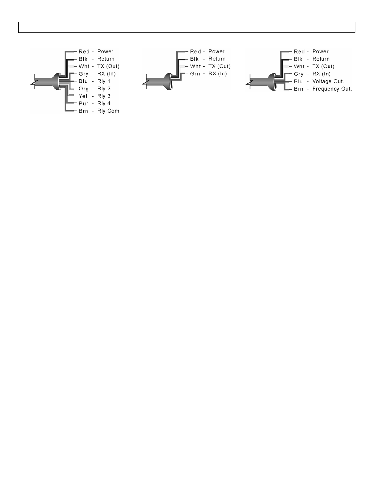
WIRING StepNine
WireConnections:
LVCN414,LVCN210,LVCN318&
LVCN414‐RSeries
Red&Black
Red and Black leads are for connection to a 24 VDC power supply or to a 4‐20 mA loop power source
(LVCN414‐I,LVCN414,LVCN210&LVCN318seriesonly).Theredandblackwirescanbeextendedupto1,000
feetusinga22gaugeorlargerwire,howeverdonotextendthegreenandwhitewires.
White&Green
White and Greenleads arereserved for use with theLVCN414‐SW software andshould not be connected
duringusageintheapplication.Thesewiresshouldnotbeconnectedtothesoftwarewhilepowerissupplied
from any source other than the LVCN414‐USB series Fob.The maximum cable distance between the
computerandthesensoris15’.
Neverallowthewhiteorgreenwirestotouchanypowersupply.
LVCN414‐ISeries LVCN414‐VSeries
Blue,Orange,Yellow,Purple&Brown–(LVCN414,LVCN210,LVCN318&LVCN414‐RSeriesonly)
Blue, Orange, Yellow & Purple wires are the relay contacts (normally open) from each of the relays
respectively.The Brown wire is the common for all the relays.Relay selection is determined by the
configuration.
Blue&Brown–(LVCN414‐VSeriesonly)
UsetheBrownwirefortheFrequencyoutput.UsetheBluewirefortheVoltageoutput.
Generalnotesforelectricalconnections,usageandsafety:
Where personal safety orsignificantpropertydamage can occur due toaspill, the installation must
havearedundantbackupsafetysysteminstalled.
Wiringshouldalwaysbecompletedbyalicensedelectrician.
Supplyvoltageshouldneverexceed28VDC.
Alwaysusestepperrelaysbetweenthe sensor and externalloads.ForDCcircuitsuseacatchdiode
suchas1N4148,shownonpreviouspage.
Protectthesensorfromexcessiveelectricalspikesbyisolatingthepower,wheneverpossible.
ThesensormaterialsmustbeChemicallycompatiblewiththeliquidstobemeasured.
Designafail‐safesystemforpossiblesensorand/orpowerfailure.
NeverusethesensorinenvironmentsclassifiedasHazardous.
31
Page 32
WIRING StepNine
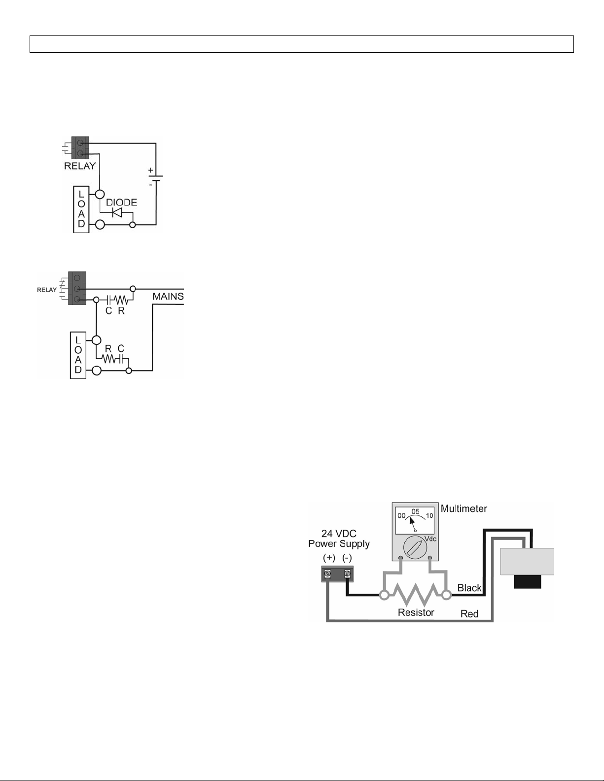
SwitchingInductiveLoads
The use of suppressors (snubbers) is strongly recommended when switching inductive loads to prevent
disrupting the microprocessor’s operation. The suppressors also prolong the life of the relay contacts.
SuppressioncanbeobtainedwithacatchdiodeforDCcircuitsandaresistor‐capacitor(RC)forACcircuits.
CatchDiode
Alwaysusestepperrelay
ForDCcircuitsuseacatchdiodesuchas1N4148,shownonleft.
RefertothefollowingcircuitsforRCnetworkassemblyandinstallation:
ChooseRandCasfollows:
R:0.5to1Ohmsforeachvoltacrossthecontacts
C:0.5to1μFforeachampthroughclosedcontacts
Notes:
1. Usecapacitorsratedfor250VAC.
2. RCnetworksmayaffectloadreleasetimeofsolenoidloads.Check
toconfirmproperoperation.
3. InstalltheRC networkatthemetersrelay screwterminals.AnRC
networkmayalsobeinstalledacrosstheload.Experimentforbest
results.
sbetweenthesensorandexternalloads.
VoltageOutput–(LVCN414‐I,LVCN414,LVCN210&LVCN318Seriesonly)
Theultrasonicsensorcanbeusedasa0to5or0to10VDCoutputdevice.Aresistorwillneedtobeaddedto
thecircuittoenableavoltageoutput(refertothewiringdiagrambelow).
0‐5VDCoutput
o Adda250Ohmresistor
o Actualoutputwillbe0.8to5VDC
0‐10VDCoutput
o Adda500Ohmresistor
o Actualoutputwillbe2to10VDC
WhenusingtheLVCN414‐SWsoftware,underNumberofPumps,select4‐20mATransmitterOnly tosimplify
theconfiguration.
32
Page 33
INSTALLATION StepTen
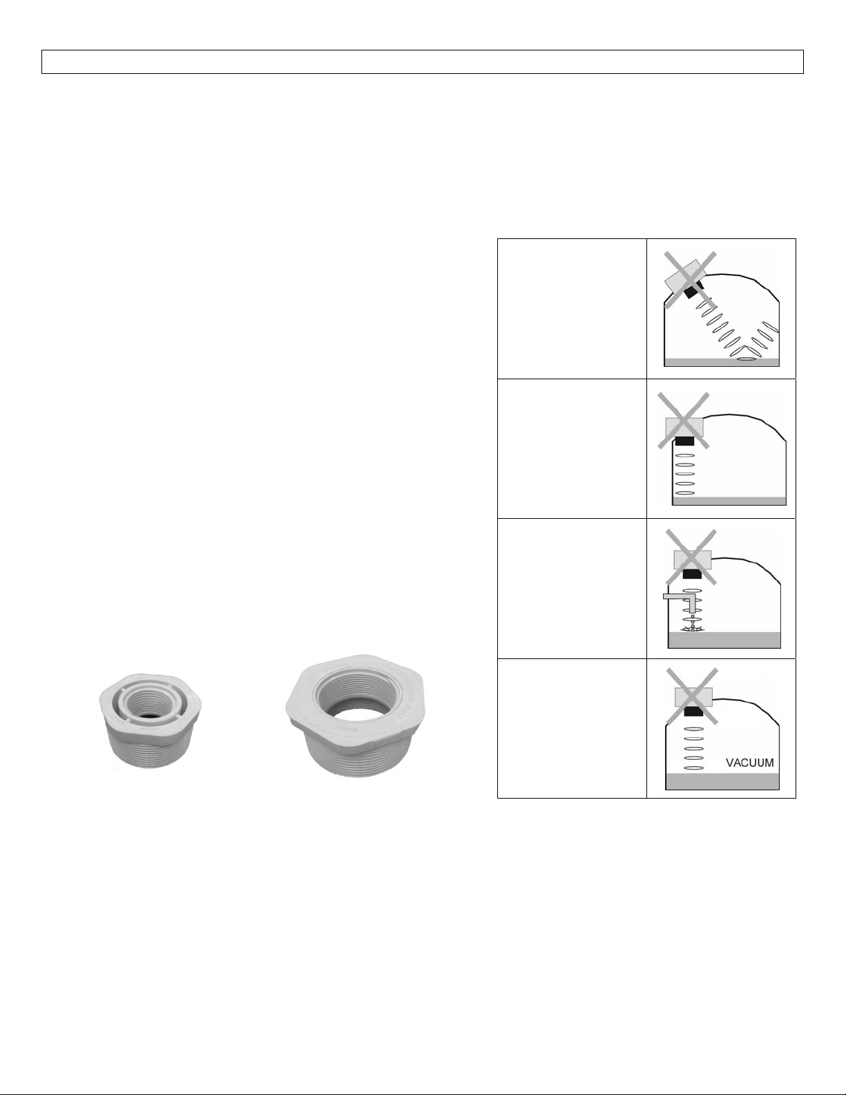
The ultrasonic sensor should always be mounted perpendicular to the liquid surfaceandinstalledusingthe
providedFKMmountinggasket.Makesurethatthefittingandtransmitterthreadsarenotdamagedorworn.
Alwayshand‐tightenthetransmitterwithinthefitting.Performaninstalledleaktestundernormalprocess
conditions prior to system start up.Note: The preferred mounting fitting for the LVCN414‐I, LVCN414,
LVCN210,LVCN414‐R&LVCN414‐Vseriesisaplastic(2”threadx1”thread)reducerbushing.
MountingGuide
1. Donotmountatanangle
2. Liquidshouldneverenterthedeadband
3. SideWall:
a. Mountatleast2”fromthesidewall
Donotinstallat
anglerelativeto
theliquid.
b. ForLVCN318Series‐mountatleast3”fromtheside
wall
4. Donot mount where obstacleswill intrude on sensor’s
beamwidth
a. SeeSpecifications,StepTwo
5. Donotmountinavacuum
Donotinstall
within3”oftank
sidewall.
6. Avoidmountinginthecenterofadometoptank.
7. In cone bottom tank, position the sensor over the
deepestpartofthetank.
Installationinexistingfittings:Iftheexistingfittingislarger
than the threads of the sensor, select a reducer bushing
suchastheLVU800‐2N40(2”threadx1”thread)orLVU800‐
Donotinstallwith
objectsinthe
beam.
3N40(3”threadx2”thread).
Donotinstallin
applicationswith
vacuum.
LVU800‐2N40
LVU800‐3N40
MetalTanks(LVU2710series)
OmegaEngineeringultrasonictransmittershavebeenoptimizedforuseinnon‐metallicfittings.
1. Forbestperformance,avoidtheuseofmetallicfittings.
a. Usea plastic2”x1”reducerbushing(suchasLVU800‐2N40)oraplastic1”tankadapter(such
asLVU800‐1B).
2. While installations directlyinto a 1”metal fitting are not recommended, acceptable results maybe
obtained if the 1”fittingis a half couplinginform and the outer diameterof the coupling is tightly
wrappedinvinyltapetodampenvibrations.
33
Page 34
INSTALLATION StepTen
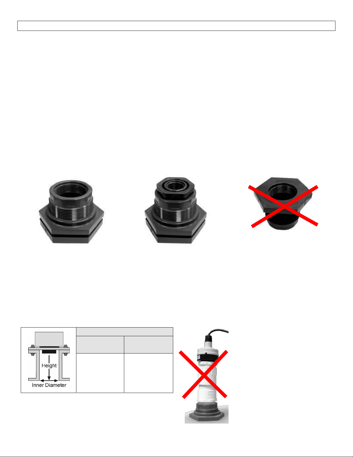
FittingSelection:Checkthepartnumber todeterminetherequiredfittingmountsizeandthreadtype.The
ultrasonic sensor is commonly installed in tank adapters, flanges, brackets or standpipes.Note: Always
includethegasketwheninstallingtheSensor.
1. Tank Adapter:Select a tank adapter fitting for the LVCN414‐I, LVCN414, L
LVCN414‐VorLVCN318series.
a. For best results, select a 2” tank adapter (LVU800‐2B) and add a plastic 2” by 1” reducer
bushing(LVU800‐2N80).
b. Avoid tank adapter (thread x thread) styles and/or pipe stops forward of the installed
transducer.
c. Alwaysmountthetankadaptersothemajorityoffittingisoutsidethetank.
i. Nevermountthetankadapterupsidedownorthebulkofthematerial
2”TankAdapter
SocketxThread
(LVU800‐2Bshown)
TankAdapter (LVU800‐2B)
w/2”x1”ReducerBushing
(LVU800‐2N80shown)
Donotusethreadxthread
TankAdapter
ThreadxThread
VCN210, LVCN414‐R,
isinsidethetank.
2. Riser:Installationswithtall,narrowriserscanimpedetheacousticsignal.
a. Core Out Concrete:Applications wheretankwithaconcreteceilingthathasbeencoredout
canalsobeconsideredasarisertypeapplication.Intheseapplicationsfollowa2:1ratio(Inner
DiametertoCoreHeight)forthediameterofthecore.
b. LVCN318Series:2”(5cm)diameterrisersshouldbenotallerthan4”(10cm).Largerdiameter
risersshouldbenotallerthan12”(30.5cm).
c. LVCN414‐I,LVCN414,LVCN210,LVCN414‐R&LVCN414‐VSeries:
RiserSpecifications
Inner
Diameter
2”(5cm)
4”(10cm)
6”(15cm)
Note:Donotexceedthedimensionslistedabove.
Maximum
Height
3”(7.6cm)
8”(20cm)
12”(30cm)
34
Note: If attempting to raise the
sensorabovethetopofthetank
toallowforahigherfillcapacity,
avoid theuseoftalland narrow
risers.The example to the left
exceeds the dimensions listed in
the Riser Specifications chart.
Use alargertankadapter which
takes into account the Riser
Specifications.
Page 35
INSTALLATION StepTen
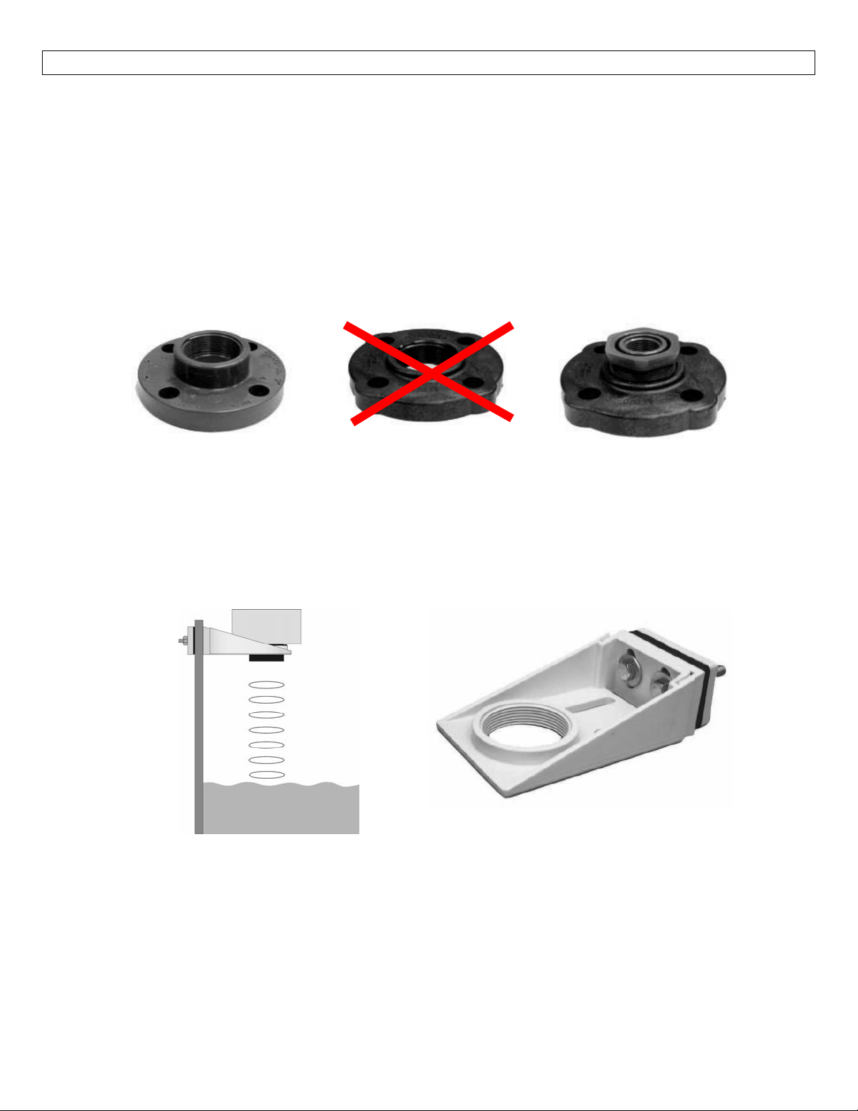
3. Flange(LVCN414‐I,LVCN414,LVCN210,LVCN414‐R&LVCN414‐Vseries):Ifinstallingonaflange,
selectaflangewithathreadthatisabovetheplaneoftheflange.
a. TheLVCN318seriesworkswellwithFlangeinstallations.
b. Avoidtheuseofblindflangeswithtappedthreadsorflangeswherethethreadsareevenwith
theplaneoftheflange,suchastheBanjo1"PolyANSIFlange(seriesAF100).
c. Useaflangewitha2”threadandadda2”to1”reducerbushingtocompletetheinstallation.
2”Flangew/
threadoutofplane
(LVU800‐2Fshown)
Donotusethreadinplane
4. SideMountBracket:Forinstallationsinopentanksandsumps,usetheLVM‐30seriessidemount
bracket.
a. FortheLVCN414‐I,LVCN414,LVCN210,LVCN414‐R&LVCN414‐Vseries,ordertheLVM‐30side
mountbracketandaddaplastic2”x1”ReducerBushing.
b. FortheLVCN318series,ordertheLVM‐30sidemountbracket.
1”Flangew/
threadinplane
2”Flangew/
reducerbushing
(LVU800‐2N80shown)
35
LVM‐30SeriesShown
Page 36
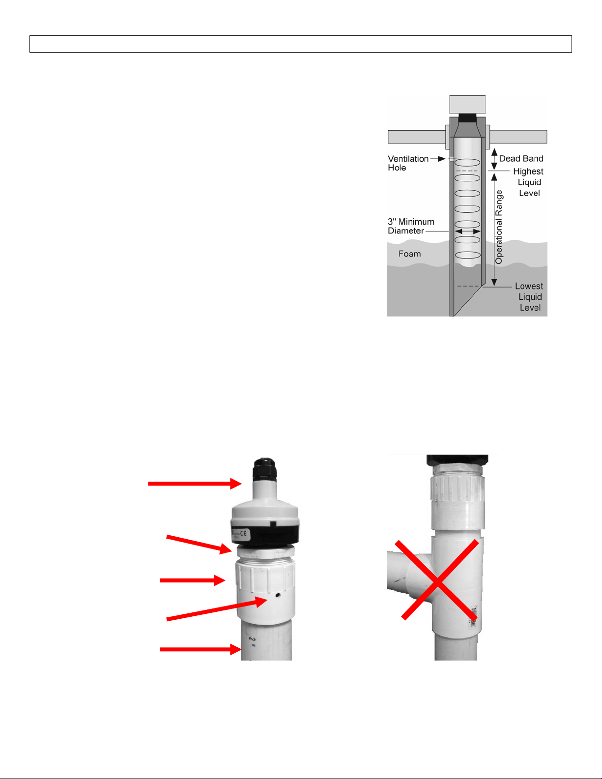
INSTALLATION StepTen
5. StandPipe:Astandpipemaybeusedtodampenturbulenceorwhenfoamispresentinthe
application.
a. Pipecanbemadeofanymaterial.
b. Selectaminimum3”IDpipeforthestandpipe.
i. A 2” pipe is usable with theLVCN414‐I, LVCN414,
LVCN210, LVCN414‐R & LVCN414‐V series, but is
theminimum.
ii. Pipeslargerthan3”canalsobeused.
c. Use a coupling and reducer bushing to attach the
sensortothepipe.
i. Besuretouseaplasticreducingbushingsuchas2”
Threadx1”Threadfitting(ex:LVU800‐2N80)or2”
Slipx1”Threadfitting(ex:LVU800‐2S80).
ii. FortheLVCN318series,useareducerbushingsuch
as3”Threadx2”Threadfitting(ex:LVU800‐2N80)
or3”Slipx2”Threadfitting(ex:LVU800‐3S80).
d. Thepipelengthshouldrunthemeasurementspanand
thebottomofthepipeshouldremainsubmergedatall
timestopreventfoamfromenteringthepipe.
e. Cuta 45° notch atthe bottom of thepipe and drill a
1/4”pressureequalizationholeinthedeadband.
f. Thepumpsshouldnotdriveliquidpasttheopenendof
the stand pipe which causes theliquid in thepipe to
oscillate.
LVCN210
Series
2”(T)x1”(T)
ReducerBushing
(LVU800‐2N40)
2”(SxT)
Coupling
VentHole(1/4”)
2”PVCPipe
LVU2710attachedtoaLLVU800‐
2N40(2”x1”reducerbushing)to
aSxT2”Coupling.
Avoidtheuseofateewithinthe
standpipe.Ateecancreatefalse
signalswhichwillinterferewith
thesensor’sperformance.
36
Page 37
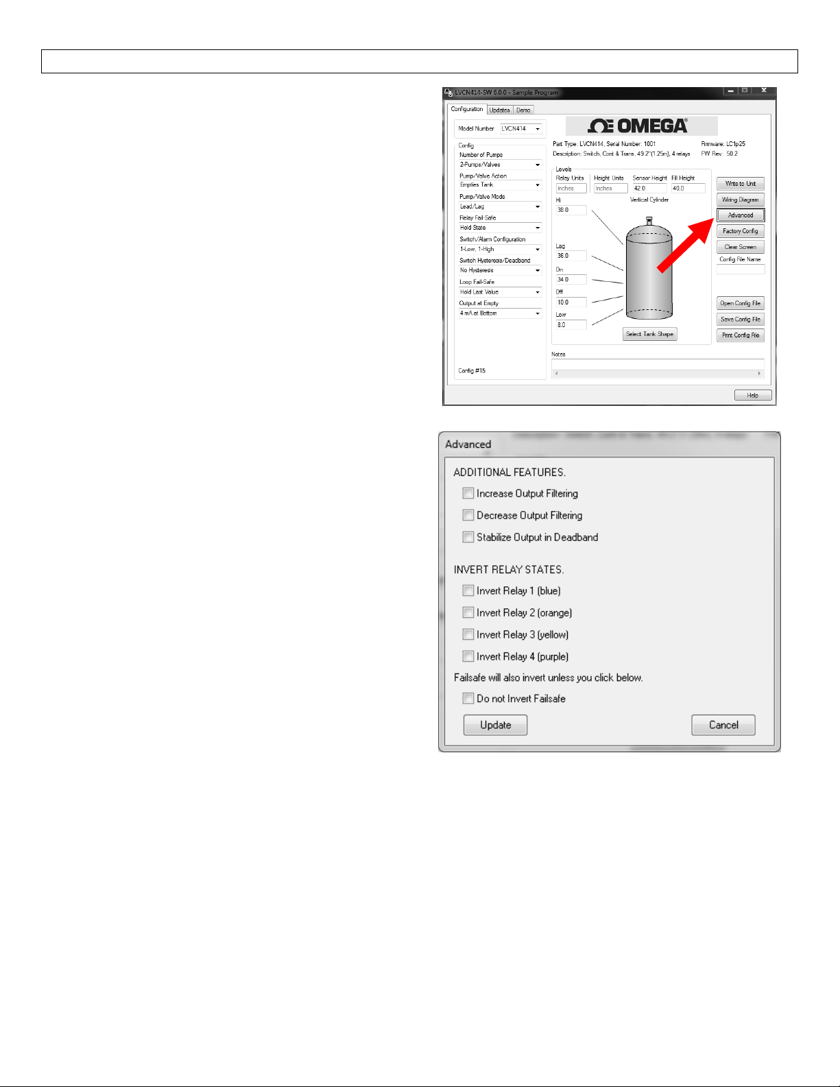
ADVANCEDFEATURES StepEleven
Thistoolis designedtohelpsolve operationalissues.
Changing these settingwill alter the performanceof
yourunit.Pleaseread through thisHELPfileto assist
you in making adjustments orifstillunclear about a
specific issue,please contact OMEGA ENGINEERING,
ApplicationsEngineering.
Note:WhentheAdvancedButtonis highlightedwith
a RED border, this indicates you have selected an
advancedfeature.
Increase Output Filtering: Placing a check
mark in the box will increase the filtering
(averaging) of the analog output.Use this
filter if the 4 to 20 mA output requires a
smooth output for the application such as
openchannelflowmeasurement.
Decrease Output Filtering: Placing a check
mark in the box will eliminate all filtering
(averaging) of the analog output.Enables a
pulsebypulselevel reading.Usethisfilterto
seechangesinlevelaftereverysoundpulse.
Note: Never check increase output filtering and
decreaseoutputfilteringatthesametime.
StabilizeOutputinDeadband:Placingacheck
markintheboxwillactivateafiltertoholdthe
outputatFullifthelevelentersthedeadband
ofthesensor.Thisfilterrequiresthelevel to
leave the deadband at asmooth and steady
rate.
InvertRelayStates:Placingacheckmarkinanyofthefourboxeswillrev
Forexample,ifrelay4isahighalarmthatenergizesabove50.0”ofliquid,checkingtheinvertboxwill
reversesotherelaywillenergizewhenitisbelow50”ofliquid.Invertingtherelaywillalsoinvertthe
fail‐safeoftherelay.Iftherelayisfail‐safeOn,Invertingtherelaywillmakeitfail‐safeOff.
ersethestateofthatrelay.
Fail‐Safewillalsoinvertunlessyoucheckbelow:Thisbutto
isinverted.
37
nwillnotinvertthefail‐safewhenarelay
Page 38
APPENDIX StepTwelve
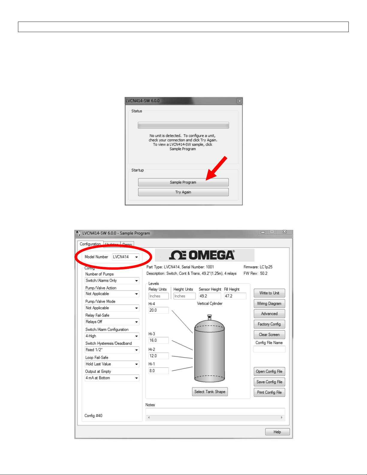
SampleProgram:AsampleversionoftheLVCN‐414‐SWsoftwareisavailableanytimeasensorisnotattached
tothesoftware.TheSampleProgram shows all thefeaturesintheConfigurationTab of the software.Any
configurationcanbeopened(OpenConfigFile),Saved(SaveConfigFile)orPrinted(PrintConfigFile)withthe
SampleProgram.SampleProgramcannotbeviewedifasensorisattachedtothecomputerviatheUSB®Fob.
ToviewtheSampleProgram,starttheLVCN‐414‐SWsoftwarewhenasensorisnotattachedtothecomputer.
Attheopeningscreen,selectSampleProgram.
Selectyourmodeltypeintheupperright‐handcorner.Note:When savingor openi
suretheModelNumbermatchesthesensorsyouintendtouse.
nga configuration,make
38
Page 39
APPENDIX StepTwelve
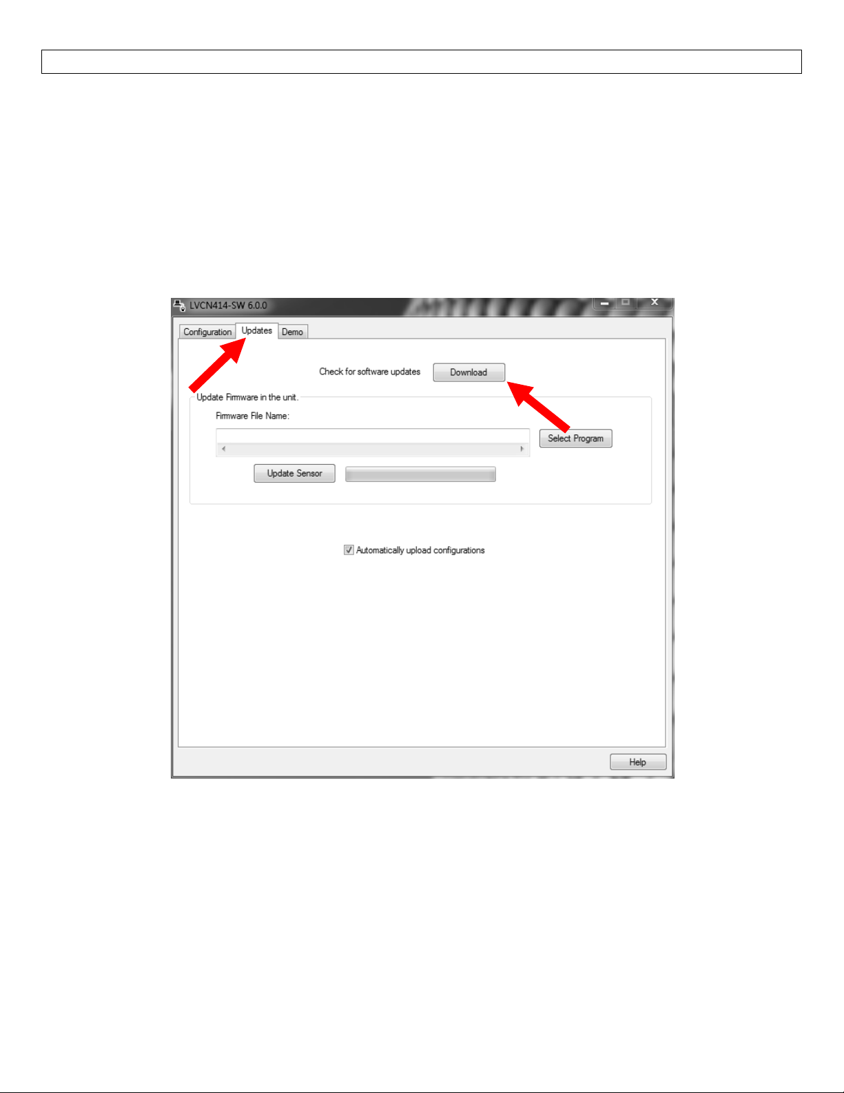
UpdatingLVCN414‐SWSoftware
Thesoftwarecanbeupdateddirectlywithinthesoftware.SimplyclickontheUpdatesTabatthetopofthe
windowandpresstheDownloadbutton.MakesurethatyourcomputerhasaccesstotheInternet.Ifnot,an
errorwindowwillappear.
WhentheDownloadbuttonispressed,thesoftwarewillchecktheversionofsoftwa
mostrecentversionatOMEGAENGINEERING.Iftheversionsaresimilar,awindowindicatingthatthemost
recentversionisinstalled.Ifnot,thenawindowwillappearaskingtodownloadthelatestversion.Followthe
instructionsforinstallingthelatestversion.
reyouareusingwiththe
39
Page 40
APPENDIX StepTwelve
UpdatingTransmitterFirmware
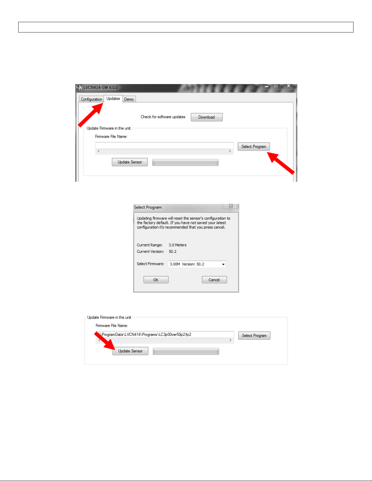
Thesoftwarecanalsobeusedtoupdatefirmwareinsidetheultrasonicsensor.Thisfeatureallowsthesensor
tobeupdatedwhennewfeaturesareadded.FirstopentheLVCN414‐SWsoftwarewithanultrasonicsensor
connectedandthelatestversionofthesoftwareinstalledtoyourPC.
ClickontheUpdatesTabandthenclickonSelectProgramtoselectthefirmwareupdate.
Selectthelatestversion
ConfirmthattheaddressiscorrectandthenclickonUpdateSensortobeginthefirmwareupdate.Thisstep
shouldtakelessthan1minute.Youcanfollowtheprogresswiththestatus
Sensorbutton.Whencompleted,clickontheConfigurationtabtoconfigurethetransmitter.Remember,
whenthefirmwarehasbeenupdated,theunitwillreturntoitsoriginalfactorysettings.
Ifthereisacommunicationinterruptionduringtheupdate,theprocesswillstop.ItisOKtoclickon
UpdateSensoragaintostarttheprocessoveragain.
ofthefirmwarefileandclickonOK.
bartotherightoftheUpdate
40
Page 41
APPENDIX StepTwelve
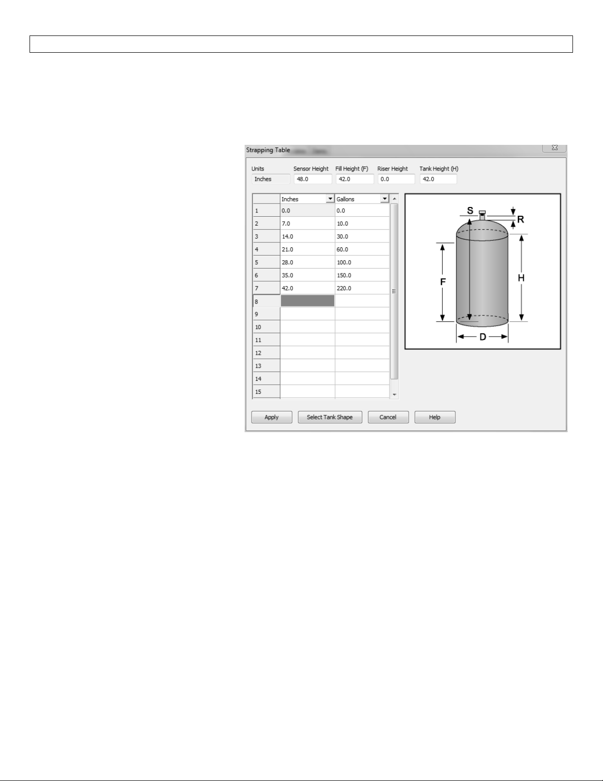
StrappingTable:LVCN‐414‐SWSoftwarefeaturesastrappingtablethatenablesyoutoenterupto16custom
referencepointsinsteadofusingthestandardtankshapes.Thisfeatureisidealforoddshapedtanksortanks
wherespecificlevelsareknownvolumesofliquid.
ToaccesstheStrappingTable,clickonStrappingTablein
Enter the Sensor Height, Fill Height,
Riser Height and Tank Height.This
information is used toconfigure the
sensortothetank.
The Strapping Table also has two
columnsof16pointsforenteringthe
knowntankdata.
Selectthedimensionsand/orvolume
at the top of the two columns
enterthetankdata.
When done, press “Apply” to
transfer the data and return to the
Configurationwindow.
and
theShapeSelectionWindowandpress“OK”.
41
Page 42
APPENDIX StepTwelve
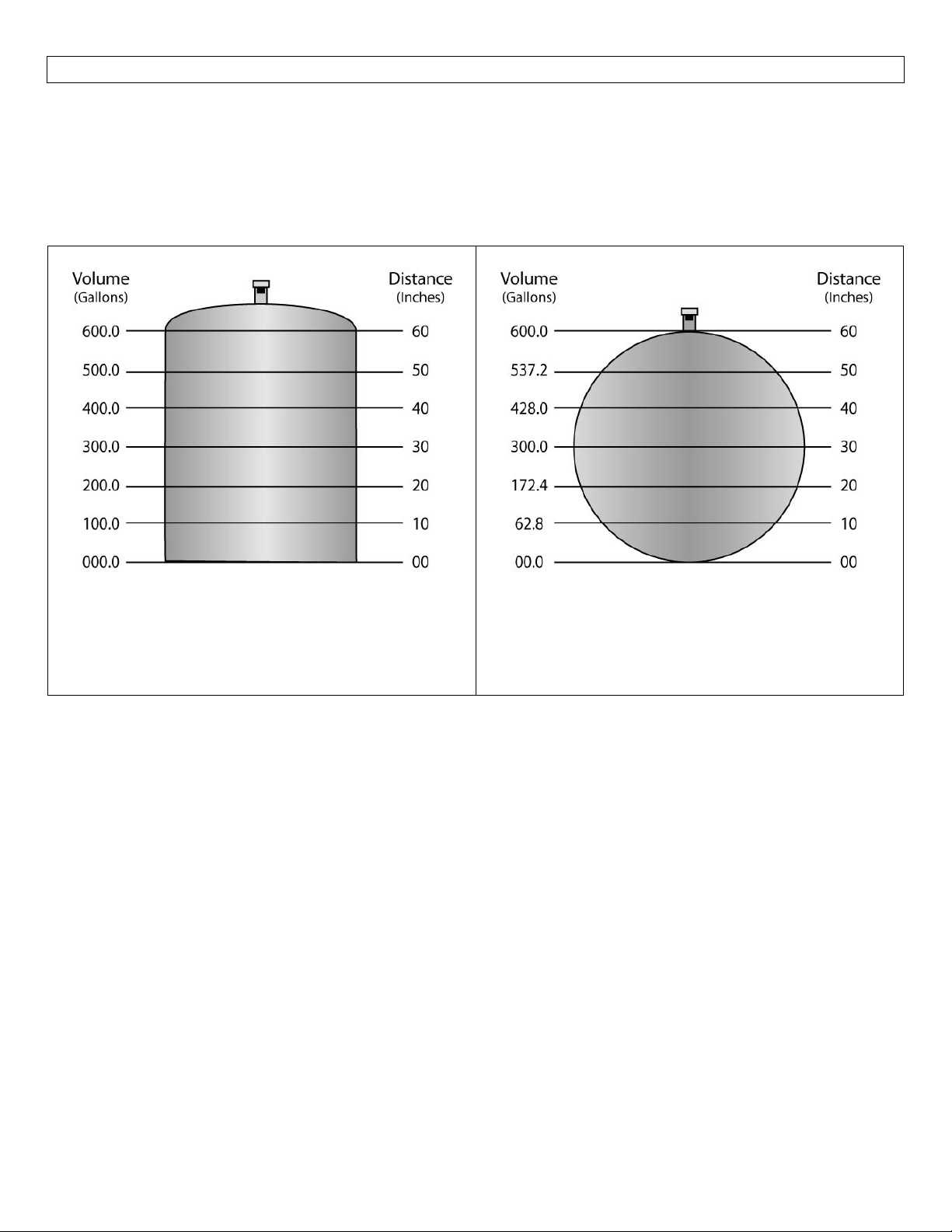
Linearvs.Non‐Linear:Twooftheshapes(VerticalCylinderTankandRectangularTank)willalwaysprovidea
linearoutput,regardlessofselectingDistance orVolume.Theremaining fourshapes(Vertical CylinderTank
withConeBottom,HorizontalCylinderTankwithEndCaps,HorizontalCylinderTank withSphericalEndCaps
andSphericalTank)willhavealinearoutputwhenDistanceisselected,butwillhaveanon‐linearoutputwhen
volumeisselected.
VerticalCylindricalTank
In the above illustration, 10” ofliquidwillalways
beequalto100gallonsofliquid(1”=10gallons).
HorizontalCylinderTankwithEndCaps
In the above illustration, 10” of liquid does not
equal 100 gallons.The 10” at the bottom
representsariseof62.8gallonswherethechange
between 10” and 20” represents an increase of
109.6gallons.
Whenvolumeisselected,the4‐20mAoutputfromthesensorwillbeproportionaltothevolumeofthetank,
nottheheightofthetank.Thismeansthatthecurrentoutputwilltrackthevolumeofthetank(ingallonsor
liters)within a non‐linear tank (Vertical Cylinder Tank with Cone Bottom, Horizontal Cylinde
Caps,HorizontalCylinderTankwithSphericalEndCapsorSphericalTank).
Whenconnectingthesignaloutputtoadisplay,thesignalwillfollowthevolumeofthetank.Thedisplaywill
alsoreflectthevolumeofthetankandnottheheightoftheliquid.
Example#1(VolumeOutput):intheaboveillustrations,@20”ofliquid,thedisplaywillshow200.0gallonsin
theVerticalCylindrical Tank.However, intheHorizontalCylinder TankwithEndCaps, thesamelevelof 20”
wouldshow172.4gallons.
rTankwithEnd
42
Page 43
APPENDIX StepTwelve
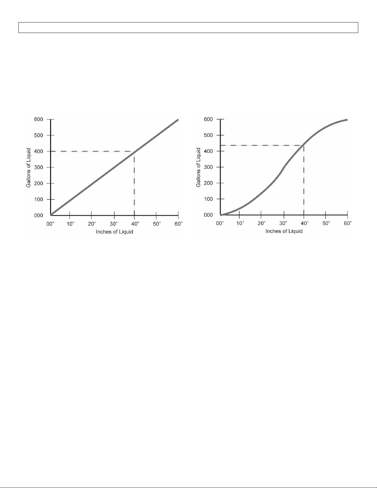
Example #2 (Current Output):In the illustrations on the previous page, the 4mA signal is set at 0” (0.0
gallons)andthe 20mAsignalissetto60” (600.0gallons).Inthe VerticalCylindricalTank,40”ofliquidwill
outputacurrentsignalof14.67mA.However,intheHorizontalCylindricalTank withEndCaps, 40”ofliquid
will output a currentsignal of 15.41mA.A simpleloop display set with4mA = 0 gallons and20 mA = 600
gallonswill show two different volumes based upon the tank shape configuration.Vertical Cylindrical Tank
willshow400.0gallonswhileHorizontalCylindricalTankwithEndCapswillshow428.0gallons.
VerticalCylindricalTank
In the above illustration, 10” ofliquidwillalways
beequalto100gallonsofliquid(1”=10gallons).
HorizontalCylinderTankwithEndCaps
In the above illustration, 1” of liquid does not
equal 10 gallons.The 10” at the bottom
representsariseof62.8gallonswherethechange
between 10” and 20” represents an increase of
109.6gallons.
43
Page 44
TROUBLESHOOTING StepThirteen
FactoryDefault
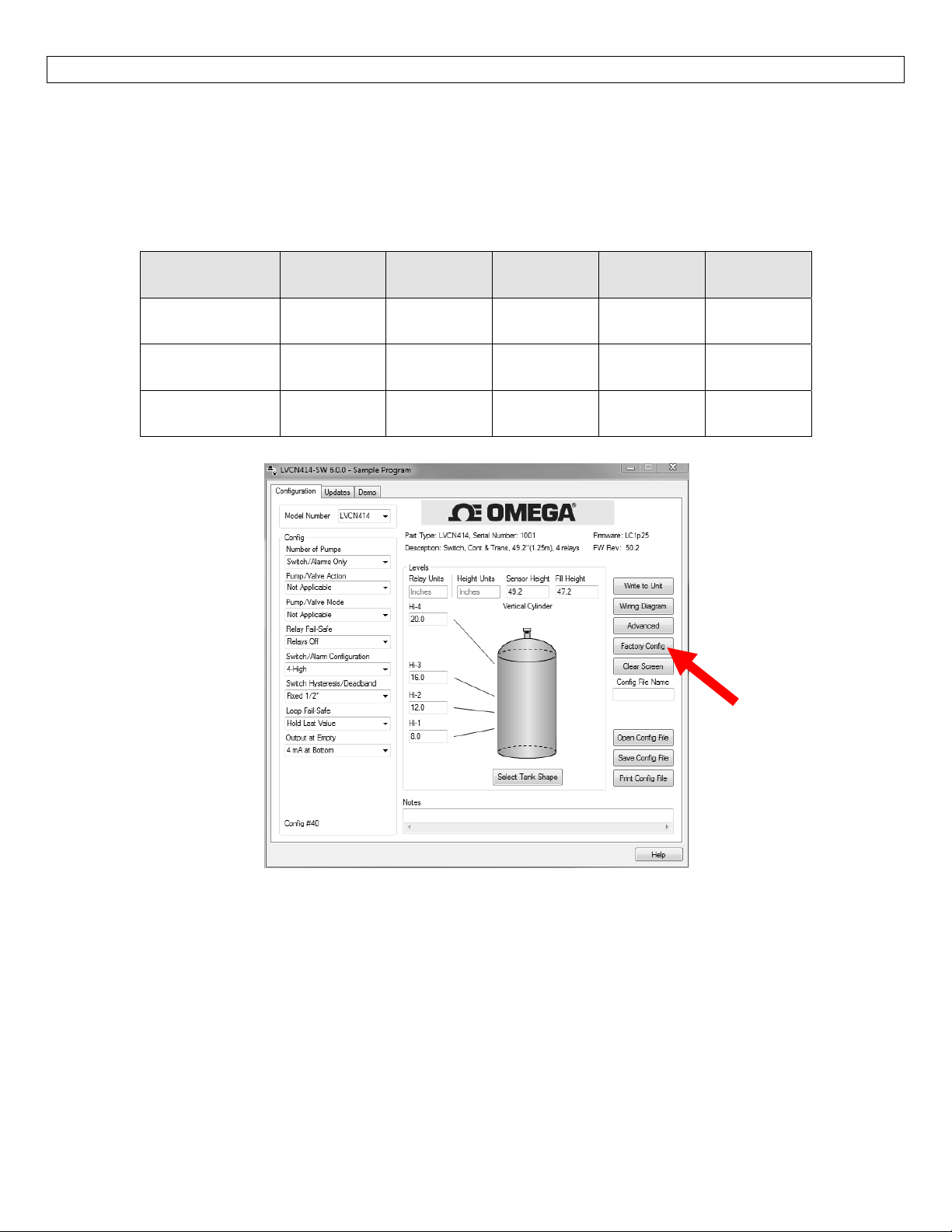
PressingtheFactoryConfigbuttonintheConfigurationmenuwillreturnthescreentothefollowingsettings.
Outofthebox,theultrasonicsensorwilloutputa4‐20mAoutputthatismaximizedforitsoperationalrange.
The transmitter can be used in the original factory setting without configuration with the LVCN4141‐SW
Software.Usethetablebelowtoidentifytheconfigurationofthesensoroutofthebox.
FactoryDefaultsTable
Part
Number
LVCN414
Series
LVCN210
Series
LVCN318
Series
Sensor
Height
49.2”
(125cm)
118.1”
(300cm)
216.5”
(550cm)
Fill
Height
47.2”
(119.8cm)
114.1”
(290cm)
530cm
(208.7”)
Loop
Fail‐Safe
Overfill
(22mA)
Overfill
(22mA)
Overfill
(22mA)
Output
atEmpty
4mA@
Bottom
4mA@
Bottom
4mA@
Bottom
Startup
Condition
Empty
Empty
Empty
44
Page 45
TROUBLESHOOTING StepThirteen
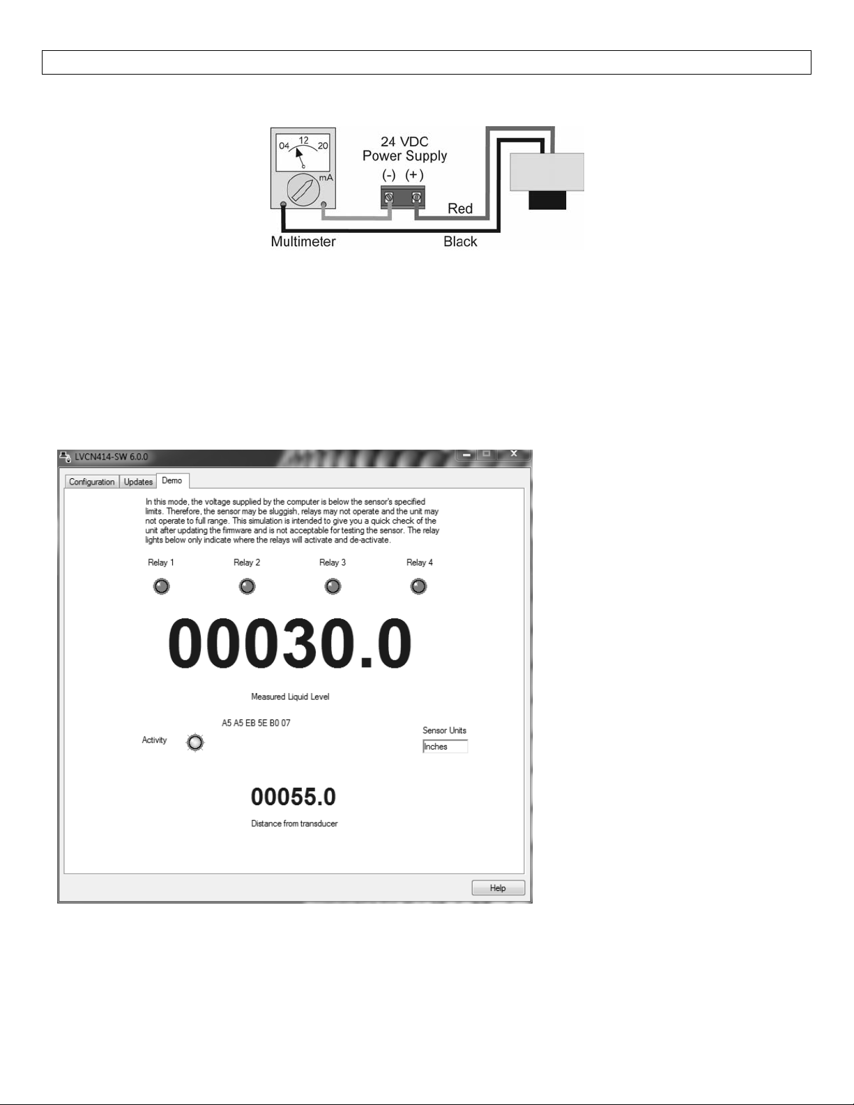
TestingtheTransmitter–LVCN414‐I,LVCN414,LVCN210,LVCN318seriesonly
1. Connectamultimeterinserieswiththeblackwiretoreadthecurrentoutput.
2. Verify that the current increases (tank filling) and decreases (tank emptying) appropriately in the
calibratedspan.
Ifnot,carefullyobserveandattempttocorrelateanyinstallation,levelorapplicationeventformorespecific
troubleshootingdirection.
DemoPage
ToviewtheDemopage(shownhere),clicktheDemotabonthetopofthescreen.
The demo page is a simulation,
useful for verifying the
configuration.There is not
enoughpowergoingtotheunitto
power the relays in the Demo
mode.The larger numbers
represent the liquid level while
the smaller numbers show the
distance from the transducer to
thesurface.
45
The senor must be pointed at a
flatperpendicularsurfacewhilein
the Demo mode.If not, the
displaywillreadLOST.
If the displa
thenthetargetisfurtheraway
from the sensor than the
SensorHeightsetting.
Ifthedisplayreads FULL, then
the target is closer to the
sensor than the Fill‐Height
setting.
y reads EMPTY,
Page 46

TROUBLESHOOTING StepThirteen
PROBLEM SOLUTION
Transmitterindicatesa
currentof0mA
Transmitterjumpstoa
currentreadingbetween
19and20mA
Transmitterindicatesa
currentover23mA
Transmitteralwaysjumps
totheLOSTcondition
Outputoftransmitteris
oppositeofthelevelof
liquid
NoUnitDetected LVCN414‐SW software cannot detect the sensor connected to the
Interneterror.Theserver
nameoraddresscouldnot
beresolved.
Check the wiring for an open circuit.An open circuit is the most
commonissuewitha0mAsignal.
Check the installation ofthetransmitter.Bad installation fittings will
causefalsesignalsnearthetopofthetank,whichtypicallytranslates
to a signal between 19 and 20 mA.Also look for interference just
belowthetransmitter.If thetransmitteris installedina metalfitting,
switchtoaplasticfitting.
Immediatelycheckthewiringforashortcircuit.Thesensoriscurrent
limitedto22mA.Anythingabove23mAindicatesashortcircuit.
Checkthedimensionalconfiguration (Height andFill‐H)ofthesensor.
Makesurethat theFill‐Hsetting correspondstothefulllevelofliquid
(fromthebottomup)andnotthedistancefromthetransmittertothe
liquid(topdown).
ChecktheOutputatEmptySetting.
computer.
CheckthattheFobisconnectedtotheUSBport.
Checkthatallfourwires(Red,Black,WhiteandGreen)aresecurely
attachedtotheFob.
Check in Device Manager that both drivers (Configuration &
EchoFob)arepresent.
Thisisawarningindicatingthecomputerconfiguringthesensorisnot
connected to the internet.Click OK to continue.OMEGA
ENGINEERING recommends being connecting to the internet for all
configurations.Not being connected tothe internet will notprevent
thesensorfrombeingconfigured.
Toturnoffthiswarning,goto theUpdatesTabandclick onthecheck
box “Automatically upload configurations”.Click on NO in the new
windowandthepreviouscheckboxwillbecomeunchecked.WebCal™
willnolongerattempttoconnecttotheinternet.Clickingonthecheck
boxwillrestorethisfeature.
Cannotaccesssomeofthe
featuresinConfiguration
Relaycloses,butdoesnot
openagain
Relaychattersonandoff
repeatedly
As choices are made in Configuration, the software will begin to
eliminatefunctionsthatarenolongeractive.ToresetConfigurationor
getaccesstoallthefeatures,clickontheClearScreenbutton.
Aninductivekickmaybeholdingtherelayclosed.Ifswitching24VDC,
use a diode thathas been installed toactas a snubber (seepage 25
and26).
Mostlikelythe turbulenceinthe tankiscausingthechatter.Increase
theHysteresissettingtocorrect.
46
Page 47

47
Page 48

48
 Loading...