

Page 1

123
Page 2

Page 3

INTRODUCTION/TABLEOFCONTENTS StepOne
The LVCN‐20 and LVCN‐100 Series are general‐purpose level controllers offered in two configurations for
pump and valvecontrol.The LVCN‐100 Series features a single 16A SPDT relay output and can accept one
level sensor as an input.Thispackage has an optional flashing alarm and is idealfor high level or low level
alarm/control.TheLVCN‐20Seriesfeaturesasingle16ASPDTlatchingrelayoutputandcanacceptoneortwo
levelsensor(s)asaninput.Thispackageisidealfortheautomaticfillingoremptyingofatank.Packageeither
controllerserieswithlevelswitch
Features
Fail‐Saferelaycontrolofpumps,valvesoralarmswitha0to60seconddelay
Optionalflashingalarmbringsimmediateattentiontolevelalarmconditions.
PolypropyleneenclosureratedNEMA4Xwithswivelbaseforconduitalignment.
EasysetupwithLEDindicatorsfor
InvertswitchchangesrelaystatefromNOtoNCwithoutrewiring.
ACpowered
TableofContents
Specifications:.........................................................................................................................................................4
Dimensions:.............................................................................................................................................................4
SafetyPrecautions:.................................................................................................................................................5
MakeaFail‐SafeSystem:............................................................................................................................6
Components:...............................................................................................................................................6
GettingStarted:.......................................................................................................................................................7
FeaturesoftheLVCN‐100&LVCN‐110seriesSingleInputController:......................................................7
FeaturesoftheLVCN‐20seriesDualInputController:..............................................................................7
GuidetoControls:.......................................................................................................................................8
Electrical..................................................................................................................................................................9
ConnectingSwitchestoInputTerminals:...................................................................................................9
VACPowerInputWiring:............................................................................................................................9
RelayInputWiring:.....................................................................................................................................9
Changingfrom120to240VAC.................................................................................................................10
Installation............................................................................................................................................................11
ApplicationExmaples............................................................................................................................................12
LowLevelAlarm:.......................................................................................................................................12
HighLevelAlarm:......................................................................................................................................12
LEDIndication:..........................................................................................................................................12
AutomaticFill:...........................................................................................................................................13
AutomaticEmpty:.....................................................................................................................................13
Appendix...............................................................................................................................................................14
ControllerLogic.........................................................................................................................................14
RelayLatchingLogicTable(LVCN‐20only)...............................................................................................14
Troubleshooting........................................................................................................................................14
sensorsandfittings.
sensor(s),powerandrelaystatus.
Page 4
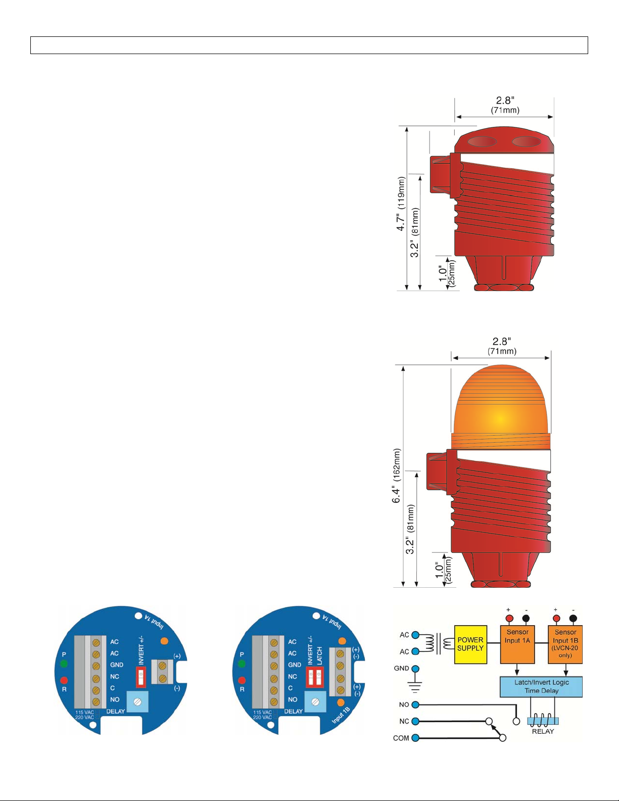
SPECIFICATIONS/DIMENSIONS StepTwo
Controller
Supplyvoltage: 120/240VAC,50‐60Hz.
Consumption: 5Wattsmax.
Sensorinputs: (1)levelswitch
(LVCN‐20seriesonly) (1or2)levelswitches
Sensorsupply: 13.5VDC@27mA
LEDindication: Sensor,relay&powerstatus
Contacttype: (1)SPDTRelay
(LVCN‐20seriesonly) (1)SPDTRelay,Latched
Contactrating: 250VAC,16A
Contactoutput: SelectableNOorNC
Contactdelay: 0to60seconds
Contactlatch: SelectOn/Off‐LVCN‐20only
Electronicstemp.: F:‐40°to158°
C:‐40°to70°
Enclosurerating: NEMA4X(IP65)
Enclosurematerial: PP(U.L.94VO)
(LVCN‐20seriesonly) PP(U.L.94VO)andPolycarbonate
Enclosuremount.: 3/4”NPT
Enclosurerotation: 300°swivelbase
Conduitentrance: Single,1/2"NPT
Certificatenumber: LR79326‐3
CEcompliance: EN61326EMC
EN61010‐1Safety
FlashAlarm(includedwithLVCN‐100only)
Flashtype: Xenontube
Flashfrequency: 1persecond
Strobelife: 10Mcycles
Supplyvoltage: 120VAC,50‐60Hz.
Consumption: 3Wattsmax.
Material: Polycarbonate
Enclosurerating: NEMA4X(IP65)
Color: Amber
SideView
LVCN‐20&LVCN‐110Series
SideView
LVCN‐100Series
LVCN‐100&LVCN‐110Series LVCN‐20Series FunctionalDiagram
4
Page 5

SAFETYPRECAUTIONS StepThree
AboutThis Manual:PLEASEREADTHE ENTIREMANUALPRIORTO INSTALLINGORUSINGTHISPRODUCT.
This manual includes information on three different models of Compact Relay Controllers from Omega
Engineering:LVCN‐100, LVCN‐110 andLVCN‐20.The LVCN‐110 seriesis a single‐input controller with an
optionalFlashAlarmwiththeLVCN‐100series,andtheLVCN‐20isadual‐inputcontroller.Manyaspects
ofinstallationandusearesimilarbetweenthethreemodels.
User’s Responsibility for Safety:OMEGAENGINEERING manufactures severalmodelsof controller, with
differentmountingandswitchingconfigurations.Itistheuser’sresponsibilitytoselectacontrollermodel
that is appropriate for the application, install it properly, perform tests of the installed system, and
maintainallcomponents.
Electrical Shock Hazard:It is possible to contact components on the controller that carry high voltage,
causing serious injury or death.All power to the controller andthe relay circuit(s) itcontrols should be
turned OFF prior to working on the controller.If it is necessary to make adjustments during powered
operation,use extremecautionand useonlyinsulatedtools.Making adjustmentstopoweredcontrollers
isnotrecommended.Wiringshouldbeperformedbyqualifiedpersonnelinaccordancewithall applicable
national,stateandlocalelectricalcodes.
FlammableorExplosiveApplications:Sensormountcontrollersshouldnotbeusedwithexplosiveor
flammableliquids,whichrequireanintrinsicallysafeorexplosionproofrating.Ifyouareunsureofthe
suitabilityofacontrollerforyourinstallation,consultyourOmegaEngineeringrepresentativeforfurther
information.
InstallIn a Dry Location:The LVCN‐100, LVCN‐110 & LVCN‐20seriescontrollerhousingisliquid‐resistant
andmadeofPolypropylene(PP).Wheninstalledproperly,the controllerisnot designedtobe immersed.
It should be mounted in such a way thatit does not normally come into contactwith fluid. Refer to an
industryreferencetoensurethatcompoundsthatmaysplashontothe controllerhousingwillnotdamage
it.Suchdamageisnotcoveredbythewarranty.
RelayContact Rating:Therelayisratedfor a 16 ampresistiveload.Manyloads(such asamotorduring
start‐uporincandescentlights)are reactiveandmayhaveaninrush currentcharacteristicthatmaybe10
to 20 times their steady‐state load rating.The use of a contact protection circuit may be necessary for
yourinstallationifthe16ampratingdoesnotprovideanamplemarginforsuchinrushcurrents.
5
Page 6

SAFETYPRECAUTIONS(cont.) StepThree
Make a Fail‐Safe System: Design a fail‐safe system that accommodates the possibility of relay or power
failure.If power is cut off to the controller, it will de‐energize the relay.Make sure that the de‐energized
stateoftherelayisthesafestateinyourprocess.Forexample,ifcontrollerpowerislost,apumpfillingatank
willturnoffifitisconnectedtotheNormallyOpensideoftherelay.
While the internal relay is reliable, over the course of time relay failure is possible in two modes: under a
heavyload thecontactsmaybe “welded”orstuckinto the energizedposition,orcorrosion maybuildupona
contact so that it will not complete the circuit when it should.In critical applications, redundant backup
systems and alarms must be used in addition to the primary system.Such backup systems should use
differentsensortechnologieswherepossible.
While this manual offers some examples and suggestions to help explain the operation of OMEGA
ENGINEERINGproducts, such examplesareforinformationonlyandarenotintended as a complete guide to
installinganyspecificsystem.
Sensor‐mount controllers:The LVCN‐100, LVCN‐110 & LVCN‐20 series are a cost‐effective, modular liquid
level controller whose body incorporates a female 3/4" NPT (3/4" BSP) fitting, allowing it to be mounted
directly onto any Omega Engineering sensor or any 3/4" connection.Simply provide its required AC power
and a controlled device such as a valve, pump, or alarm that can be switched by the controller’s relay in
responsetothesensorinput.
Sensor‐mountcontrollers are particularly appropriateforsimple processes such ashigh orlow alarms.They
can also be a useful part of more complicated systems, providing a fail‐safe backup in case a centralized
systemfails.
Components:
LVCN‐110 ‐SingleInputHighorLowRelayController
LVCN‐110‐CE ‐SingleInputHighorLowRelayControllerwithCEapproval
LVCN‐100 ‐SingleInputHighorLowRelayControllerwithFlashingAlarm
LVCN‐100‐CE‐SingleInputHighorLowRelayControllerwithFlashingAlarm&CEapproval
LVCN‐100‐220VAC ‐SingleInputHighorLowRelayControllerwithFlashingAlarmconfiguredto220VAC
LVCN‐20‐DualInputAutomaticFillorEmptyRelayController
LVCN‐20‐CE‐DualInputAutomaticFillorEmptyRelayControllerwithCEapproval
Owner’sManual
6
Page 7
GETTINGSTARTED StepFour
Features of the LVCN‐100& LVCN‐110 seriesSingle Input Controller:TheLVCN‐100 & LVCN‐110series are
designed to receive a signal from a single liquid sensor.It turns its internal relay ON or OFF (as set by the
invertswitch)inresponsetothepresenceofliquid,andchangestherelaystatusbackagainwhenthesensoris
dry.
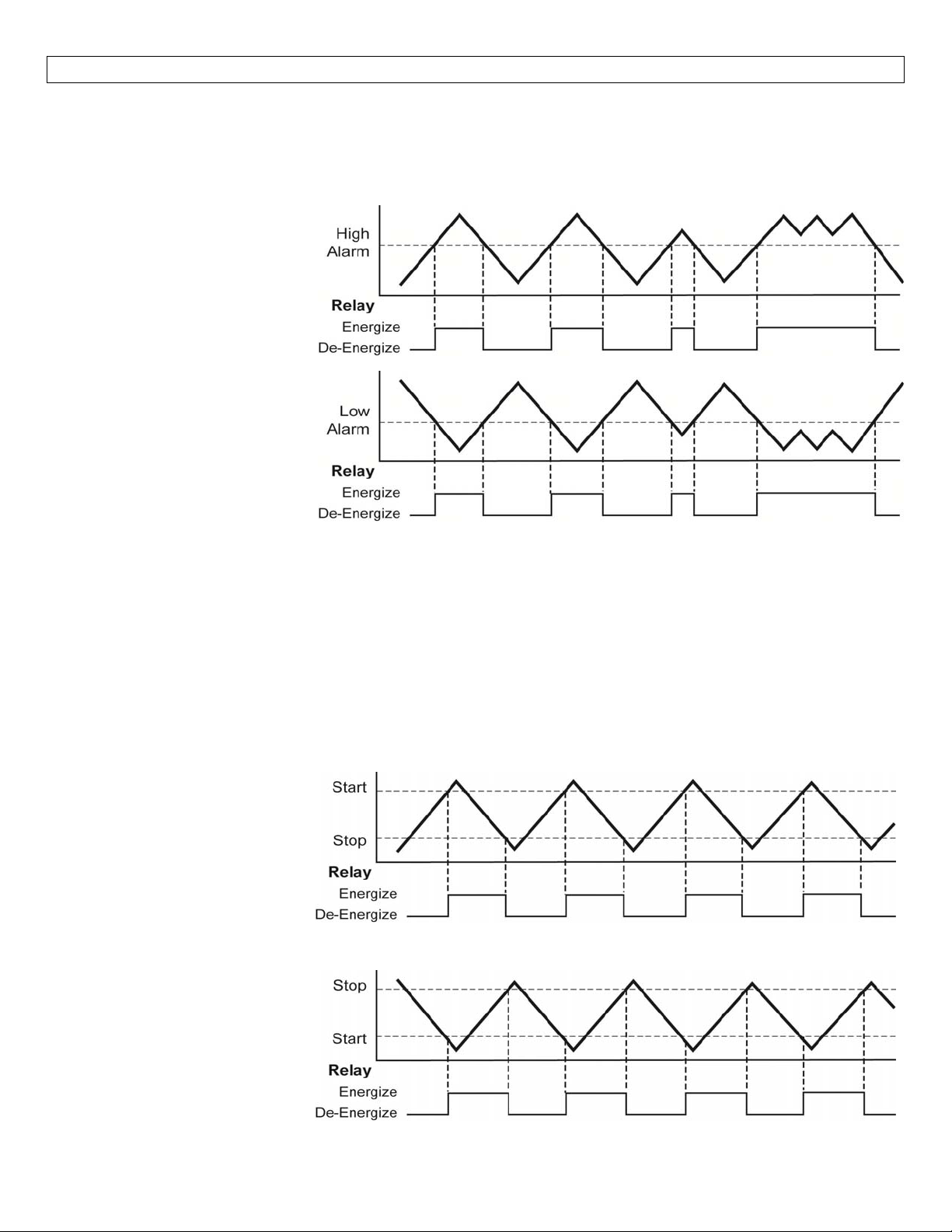
HighAlarm:
Invert is OFF.Relay will
energize when the switch
becomes Wet and will de‐
energize when the switch
becomesDry(outofliquid).
LowAlarm:
InvertisON.Relaywillenergize
when the switch becomes Dry
(out of liquid) and will de‐
energize when the switch
becomesWet.
The LVCN‐100 & LVCN‐110 series may be used with almost any kind of sensor signal: current sensing or
contact closure.The relay is a single pole, double throw type; the controlled device can be connected to
eitherthenormallyopen or normally closedsideof the relay.A time delay from 0 to60 secondscanbeset
before the relay responds to the sensor input.Typicalapplications for theLVCN‐100 & LVCN‐110 series are
highlevelorlow level switch/alarm operations (opening a drain valvewhenever liquid levelrises to a sensor
point)andleakdetection(soundinganalarmwhenaleakisdetected,etc.).
FeaturesoftheLVCN‐20 seriesDualInput Controller:TheLVCN‐20series isdesignedtoreceivesignals from
two liquid sensors.It turns its internal relay ON or OFF (as set by the invert switch) in response to the
presenceofliquidonbothsensors,andchangestherelaystatusbackagainwhenbothsensorsaredry.
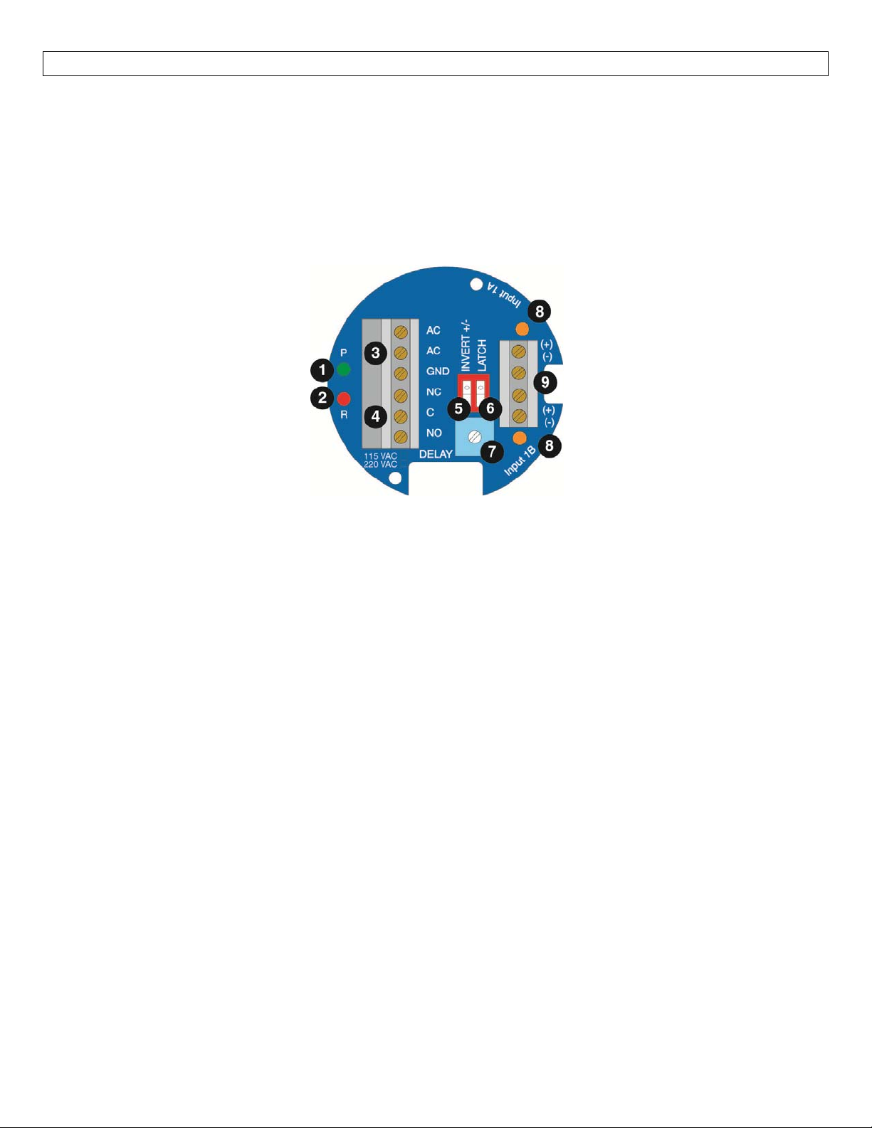
AutomaticEmpty:
Latch is OFF & Invert is OFF.
Relay will energize when level
reaches high switch (both
switches are wet).Relay
de‐energize when level is
belowthebottom switch (both
switchesaredry).
AutomaticEmpty:
Latch is OFF & Invert is ON.
Relay will energize when level
is below the bottom switch
(both switches are dry).Relay
will de‐energize when level
reaches high switch (both
switchesarewet).
will
7
Page 8
GETTINGSTARTED(continued) StepFour
TheLVCN‐20seriesmaybeusedwithalmostanykindofsensorsignal:currentsensingorcontactclosure.The
relayis a singlepole,doublethrowtype; the controlleddevicecanbe connected toeitherthenormally open
ornormallyclosedsideoftherelay.Atimedelayfrom0to60secondscanbesetbeforetherelayrespondsto
thesensorinput.Typical applications for the LVCN‐20 series are automatic filling (starting fillpump at alow
level and stopping pump at a high level) or automatic emptying operations (opening a drainvalve at a high
andclosingvalveatlowlevel).
level
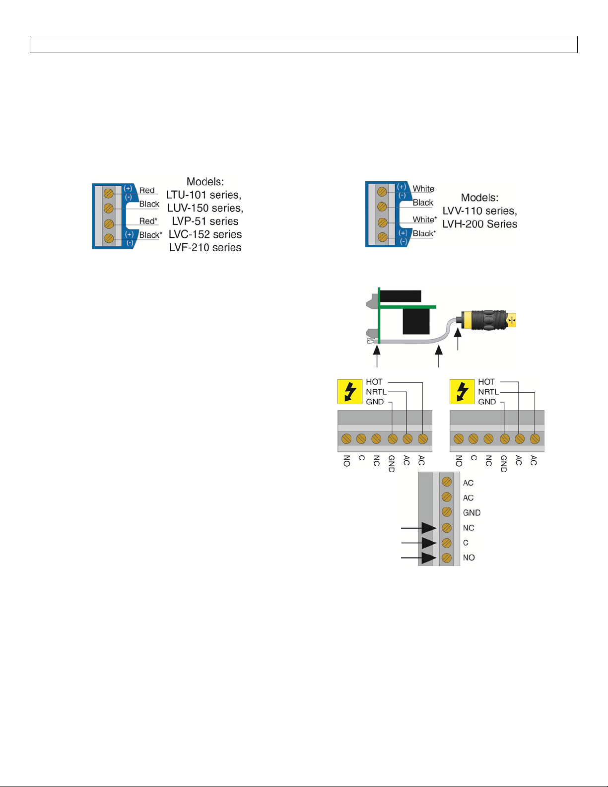
GuidetoControls:Belowisalistingandthelocationofthedifferentcomponentsforthecontroller:
1. Powerindicator:ThisgreenLEDlightswhenACpowerisON.
2. Relayindicator:This redLEDwilllightwheneverthecontrollerenergizestherelay,in
properconditionatthesensorinput(s)andafterthetimedelay.
3. ACPowerterminals:Connection of120VACpower tothecontroller.Thesetting may bechangedto
240VACifdesired.This requireschanging internal jumpers; this is covered in theInstallation section
ofthemanual.Polarity(neutralandhot)doesnotmatter.
4. Relay terminals (NC, C, NO):Connect the device you wish to control (pump, alarm etc.) to these
terminals: supply to the COM terminal, and the device to the NO or NC terminal as required.The
switched device should be a non inductive load of not more than 16 amps; for reactive loads the
current must be deratedor protection circuitsused.When the redLED is ONand the relayis in the
energizedstate,theNOterminalwillbeclosedandtheNCterminalwillbeopen.
5. Invert switch:This DIP switch reverses the logic of the relay control in response to the sensor(s):
conditionsthatusedtoenergizetherelaywillmakeitturnoffandviceversa.
6. Latch switch (LVCN‐20 series only):This DIP switch determines how the relay will be energized in
response to thetwo sensor inputs.WhenLATCH is OFF,the relay respondstosensor Input1A only;
whenLATCHisON,therelaywillenergizeorde‐energizeonlywhenbothsensors(1Aand1B)areinthe
samecondition(wetordry).Therelaywillremainlatcheduntilbothsensorschangestates.
7. Time
8. Input1Aand1Bindicator:TheseamberLEDswilllightimmediatelywheneverthe appropriate sensor
9. Inputterminals:Connectthewiringfrom thesensorstotheseterminals:Atotheupperpair,B(LVCN‐
Delay:Aftertheinput(s)change(s)state,thiscontrolsetsadelayfrom0.15to60secondsbefore
therelaywillrespond.
attachedtotheterminalsdetectsliquid,andwillturnoffwhenitisdry.
20 series only) to the lower pair.Note the polarity:(+) is a 13.5 VDC, 27 mA power supply (to be
connectedtotheredwireofanOmegaEngineeringsensor),and(‐)is thereturnpathfromthesensor
(tobeconnectedtotheblackwireofanOmegaEngineeringsensor).Ifpolarityisreversed,thesensors
willnotwork.
responsetothe
8
Page 9
ELECTRICAL StepFive
Connecting switches to input terminals:Pleasenote adifference between OMEGA ENGINEERING powered
level switches and reed switches.All powered level switches (series LTU‐101, LVU‐150, LVP‐51, LVC‐152 &
LVF‐210) will bewired with theRed wire tothe (+) terminal and theBlack wire tothe (‐) terminal.OMEGA
ENGINEERINGreedswitches(seriesLVV‐110&LVH‐200)willhaveaparticularwiringbaseduponpartnumber.
Seetheillustration below to indicate wiring foryour switch.Note:the Shield wirewill beusedonlyfor long
cablerunsorwhereexcessiveelectricalnoiseis
PoweredLevelSwitches ReedSwitches
present.
SwitchCable:WheninstallinganOmegaEngineering
level switch, adjust the cable away from the printed
circuitboards in thecontroller body.Avoid breaking
the seal between thetop of thelevel switch andthe
plasticcoatedcable.
VAC Power Input Wiring:
the LVCN‐100, LVCN‐110 & LVCN‐20 series.Note:
PolaritydoesnotmatterwiththeACinputterminal.
RelayInputWiring:Therelayisasingle pole,double
throwtyperatedat250VoltsAC,16Amps.Thetwo
terminal NO and NC (normally open
closed) will be used in different applications.
Rememberthat the "normal"state is when therelay
coilis de‐energized andtheRedrelayLED isOff/de‐
energized.
Observe the labeling on
and normally
9
Page 10
ELECTRICAL(continued) StepFive
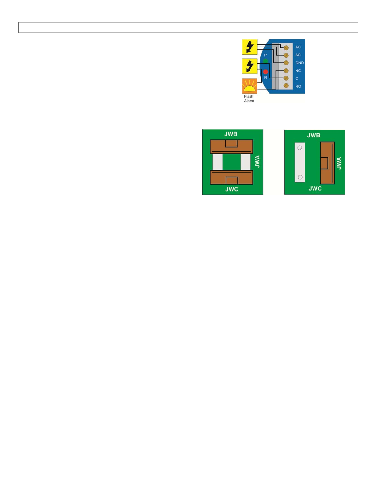
Flash Alarm Output (LVCN‐100 series):With the
FlashAlarmwired NC; it canbeusedasahighorlow
level alarm, depending on the setting for the invert
switch.TheFlashAlarmcanalsobewiredNO.
Changingfrom120to240VAC:
1. Remove the two screws from the top of the
printed circuit board (PCB) and gently slide the
PCB from the housing.Use caution when
removingthePCB.
2. LocatedjumpersJWA,JWBandJWConthePCB.
3. Tochangeto240VAC, removejumpersfromJWB
and JWC and place a single jumper across JWA.
To change to 120 VAC, remove jumper JWA and
placejumpersacrossJWBandJWC.
4. Gently return PCB into housing and replace the
twoscrews.
120VAC 240VAC
Configuration Configuration
10
Page 11
INSTALLATION StepSix
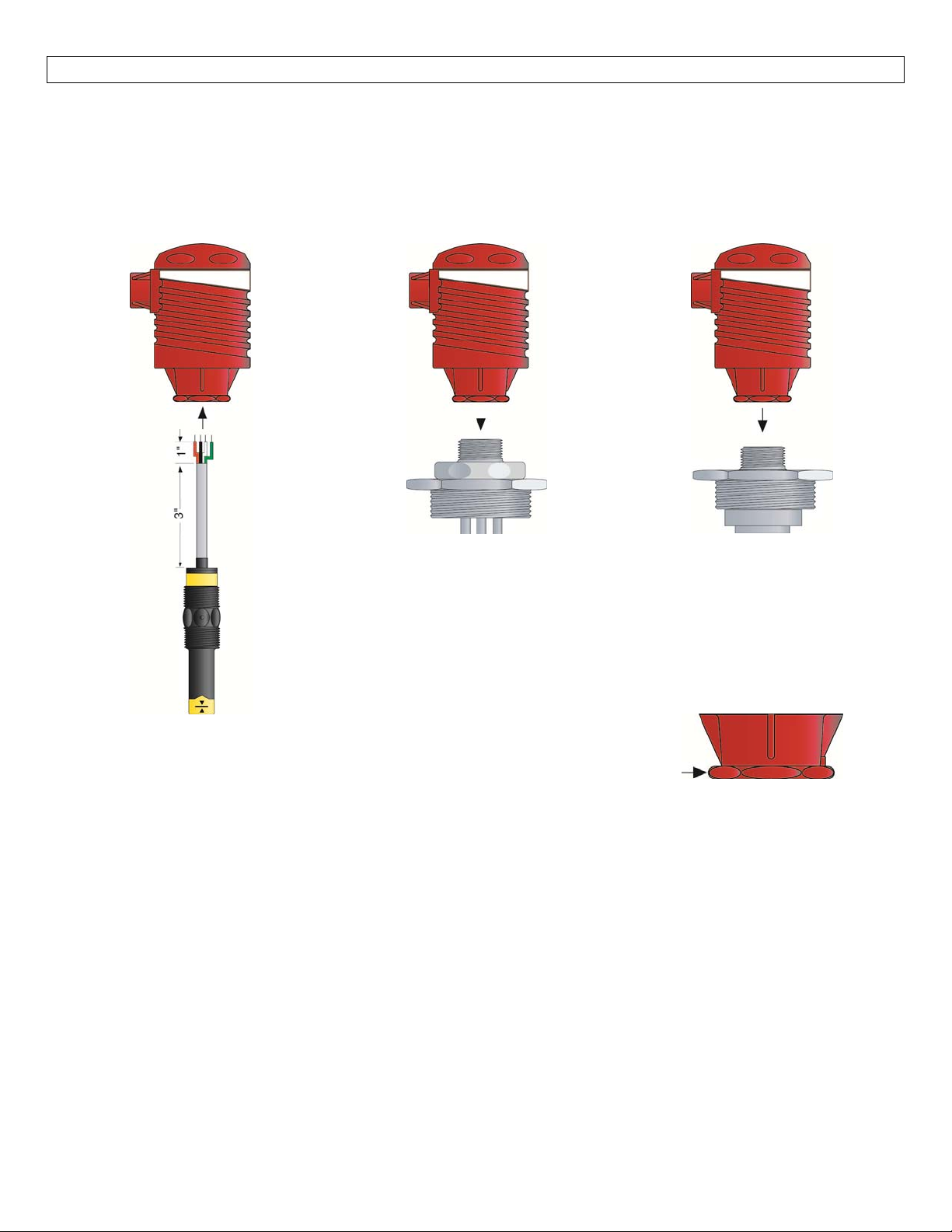
3/4" NPT Mounting Thread:Installation of the compact relay controller takes advantage of the 3/4" NPT
threadlocatedonitsbase.Thismakesthecontrollerfullycompatiblewithanyof Omega Engineering's level
switchesorLVM‐10seriesorLVM‐51Seriesmountingsystems.
Mountingdirectlytoasensor MountingtoLVM‐10Series
LevelTrackMountingSystem
MountingtoLVM‐50Series
SingleSwitchFittingAssembly
Note:Alwaystightenthecontrollerfromthe wrenchflatlocatedonthe
swivelbase.Nevertightenfromthebodyofthecontroller.
11
Page 12
APPLICATIONEXAMPLES StepSeven
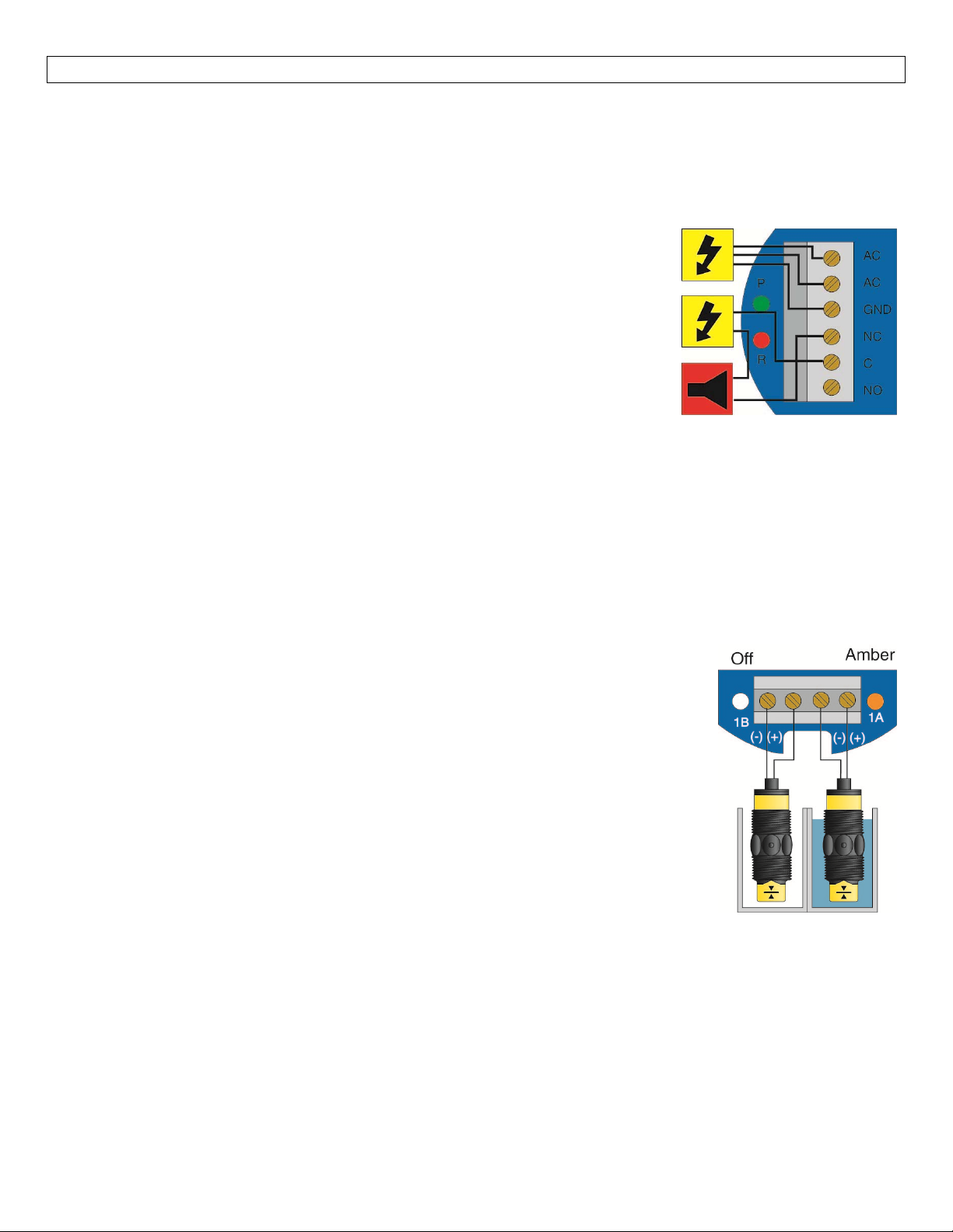
LowLevelAlarm:The goalisto makesurethattheliquidlevel doesnotfallbelowacertainpoint.Ifitdoes,
analarmissupposedtosound,alertingtheoperatorofalowlevelcondition.
Ifpowerisaccidentallycuttothecontroller,thesensor'sabilitytonotifytheoperatorofalowlevelcondition
couldbelost.Thesystemmustalerttheoperatornotonlytolowliquidlevel,buttocontrollerpowerloss.
To do this, connect the hot lead of the alarm to the NC side of the relay
terminalofthecontroller.If powerislost, therelaywillbede‐energized,and
the alarm will sound (if there is still power to the alarm circuit itself).The
alarm circuit should have a non‐interruptible power supply or some other
indicatororbackupalarmtowarnofapowerfailureinthealarmcircuit.
In this application, the normal status if the sensor at the bottom if the tank
will be wet, and the relay will be energized holding the alarm circuit open.
Both the relay LED and the Input LED will be on simultaneously, so for this
application,InvertshouldbesettotheOFFposition.
HighLevelAlarm:In thesamemanor,thissystemcanbe used to sound an alarm when fluid reaches a high
level,withjustachangeinthelocationofthesensorandthesettingoftheInvertswitch.
ThealarmisstillconnectedtotheNCsideoftherelaytoallowforapowerfailurealarm.
Thesensorisnormally dry.Inthiscondition,wewanttherelayto beenergizedsothealarmdoesnotsound:
i.e.,theRedrelayLEDshouldbeonwhenevertheInputLEDisAmber.SoweturnInvertOn.Ifthefluidlevel
risestothehighsensorpoint,thesensorgoeson,therelayde‐energizes,andthealarmsounds.
LEDIndication:UseLED'slocatedabovetheinputterminalstoindicatewhetherthe
switch is in a wet or dry state.With powered switches, Green indicates dry and
Amberindicateswet.Withreedswitches,AmberindicateswetandnoLEDindicates
dry.Note: reed switches maybe wired in reverse so that wet indicates dry and
Amberindicatesdry.
12
Page 13
APPLICATIONEXAMPLES(cont.) StepSeven
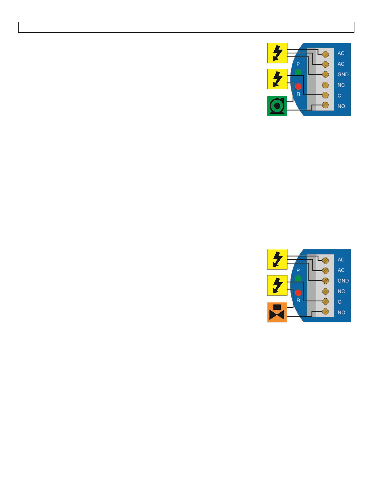
AutomaticFill:This system consists ofa tank with ahigh level sensor, a low
levelsensor,anda pumpthatis controlledbythe controller.Partofaproper
fail‐safe design for this particular system is that if power is lost to the
controller for any reason, the pump filling the tank must be turned off.
Therefore,we connectthepumptothe NO sideoftherelay.Whentherelay
is energized, the pump will turnon andfill the tank.The relay indicator will
corresponddirectlytotheON/OFFstatusofthepump.
NOTE:Ifthe pump motorload exceedstherating of thecontroller’s relay, a
stepperrelayofhighercapacitymustbeusedaspartofthesystemdesign.
DeterminingthesettingsofLATCHandINVERT:Thisisthewaythesystemmustoperate:
Whenboththehighandlowsensorsaredry,thepumpshouldturnon,startingtofillthetank.
Whenthelowsensorgetswet,thepumpshouldstayon.
Whenthehighsensorgetswet,thepumpshouldturnoff.
Latch:Inanytwo‐sensorcontrolsystem,LATCHmustbeON.
Invert:Referringtothelogicchart in Step Nine, we lookforthesettingthatwill de‐energize the relay (start
thepump)whenbothinputsarewet(AmberLEDs).Inthissystem,InvertshouldbeON.
DeterminingAorB input connections:When LATCH is ON, there is no effective differencebetweenInputA
andB,sincebothsensorsmusthavethesamesignalinorderforstatustochange.Whenwiringanytwo‐input
relaysection,theonlyconsiderationforhookingaparticularsensortoAorBisifLATCHwillbeOFF.
Automatic Empty:Note that similar system logic can be used for an
automaticemptyoperationsimplybycontrollingapumpthatpumpsfluidout
of the tank instead of into it.However, note the importance of fail‐safe
design.If the tank is being passively filled, and a pump must be used to
activelyempty it, a powerfailuretoeitherthecontroller or the pump circuits
willcauseoverflow.
Alternatively,anelectrically‐controlleddrainvalvecouldbeused.Inthiscase,
the valve should be a type that will automatically open if power is lost; in
other words, power must be used to hold it closed.The valve would be
connectedto
thepowerthatwasholdingitshut,andfluidwilldrainfromthetank into some othersafecontainmentuntil
power is restored. In this system, whenever the red relay LED of the controller is ON, the drain is closed,
allowingfluidtorise.
Inthiscase,Invertshould be ON: when both sensorsare wet,therelayde‐energizes,theswitch to the valve
opens,andthetankwilldrain.
theNOsideoftherelay—ifpowerislosttothecontroller,therelayde‐energizes,thevalveloses
13
Page 14
APPENDIX StepEight
ControllerLogic:Pleaseusethefollowingguidetounderstandtheoperationofthecontrollers.
1. PowerLED:MakesuretheGreenpowerLEDisONwhenpowerissuppliedtothecontroller.
2. Input LED(s):The input LED(s) on the controller will be Amber when the switch(es) is/are wet and OFF
whentheswitch(es)is/aredry.IftheLED'sarenotswitchingtheinputLED,testthelevelswitch.
3. LVCN‐100 & LVCN‐110 only:Whentheinput LED turn OFFandON, the relay LEDwillalso switch.With
invertOFF,therelayLED will be ON whenthe input LED is ONand OFF whenthe input LED is OFF.With
invertON,therelayLEDwillbeOFFwhentheinputLEDisONandONwhentheinputLEDisOFF.
4. LVCN‐20 only:When both inputs are wet (Amber LED's ON), the relay will be energized (Red LED ON).
Afterthat, if oneswitch becomes dry,the relay will remainenergized.Only when both switchesaredry
(both amber LED's OFF) will the controller de‐energize the relay.The relay will not energize again until
bothswitchesarewet.SeetheRelayLatchLogicChartbelowforfurtherexplanation.
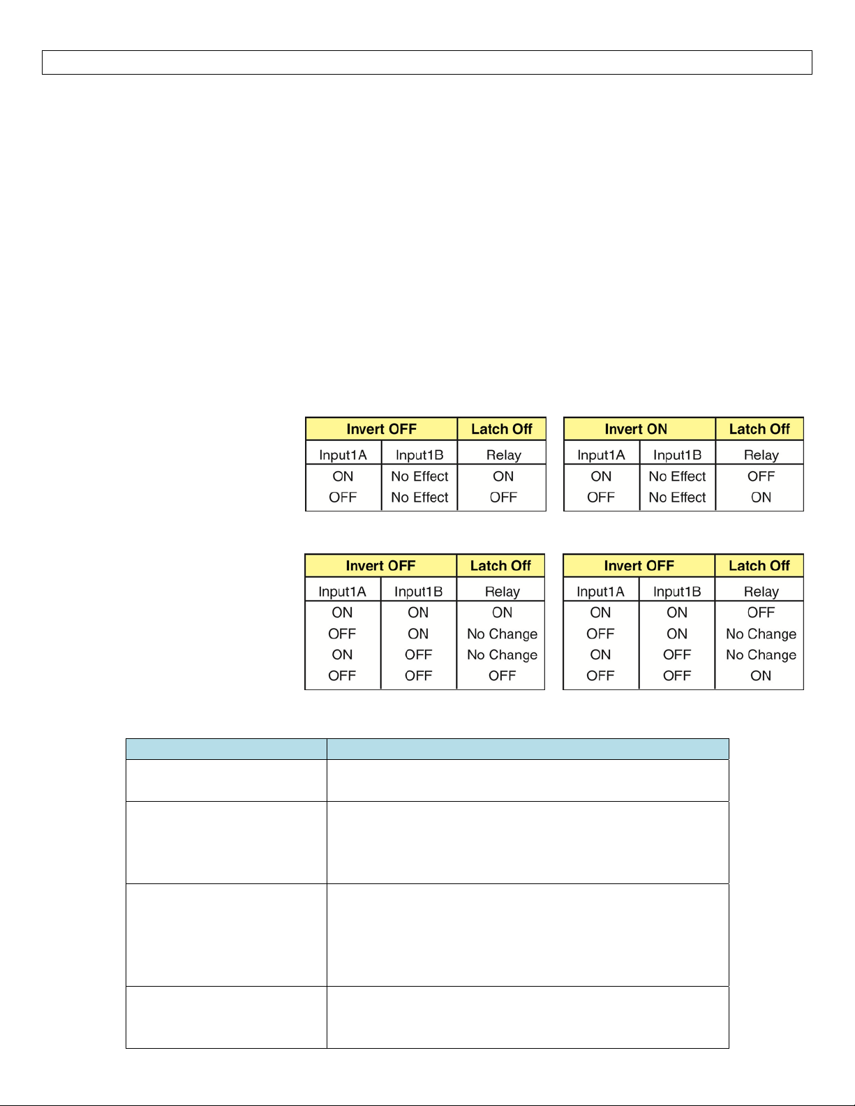
Relay Latch Logic Table (LVCN‐20 only):The relay can either be an independent relay (high or low level
alarm)or can be a latching relay(automatic fill orempty) with latchON.With Latch OFF, the relay will only
respondtotheINPUT1Asetting.INPUT1Bwillbeignored.
With Latch ON, the relay will
actuatewhenINPUT1AandINPUT
1Bare in the samecondition.The
relay will not change its condition
until both inputs reverse their
state.
Caution:Some sensors
(particularly buoyancy sensors)
may have their own inverting
capability (wired NO or NC).This
will change the logic of the invert
switch.Checkyoursystemdesign.
Troubleshooting
PROBLEM SOLUTION
Relayswitchesonlyfrom
input1A(ignoresinput1B)
LevelreachesalarmON,
butrelayisOFF.
PumporValveissupposed
tostop,butitdoesnot.
Controllerispowered,but
nothinghappens.
LatchisturnedOFF.FlipthelatchswitchtoturnON.
First, check to make sure the input LED is ON.If not,
checkwiringtosensor.
Second, check statusof RelayLED.If incorrect,flip the
Invertswitchtochangetherelaystate.
First,checktomakesuretheinputLEDsarebothinthe
satestate(bothONorbothOFF).Ifnot,checkwiringto
sensoreachsensor.
Second, check statusof RelayLED.If incorrect,flip the
Invertswitchtochangetherelaystate.
First check the Power LED to make sure it is Green.If
not,checkthewiring,powerandmakesuretheterminal
isseatedcorrectlyoverthe6‐pins.
14
Page 15

1516
Page 16

 Loading...