

Page 1

1
Page 2

2
Page 3

INTRODUCTION/TABLEOFCONTENTS StepOne
The LVCN‐120/‐130/‐140 Series Controllers are general‐purpose level controllers offered in three
configurationsfor pumpand valvecontrol.TheLVCN‐140Series featuresasingle10ASPDTrelayoutputand
canacceptonelevelsensorasaninput.TheLVCN‐130Seriesfeaturesasingle10ASPDTlatchingrelayoutput
and can accept one or two level sensor(s) as an input.This package is ideal for the automatic filling or
emptying of a tank.The LVCN‐120 Series features both a single 10A SPDT and asingle 10A Latching SPDT
relay.This packageallowsforathree‐input
and an alarm operation (high or low).The LVCN‐120 series can also be a two‐input controller that can
performdualalarms(2‐high,2‐lowor1‐high,1‐low).Packageeithercontrollerserieswithlevelswitchsensors
and
fittings.
Features
Fail‐Saferelaycontrolofpumps,valvesoralarmswitha0to60seconddelay
Optionalflashingalarmbringsimmediateattentiontolevelalarmconditions.
PolypropyleneenclosurecanbeDINrailmountedorbackpanelmounted.
EasysetupwithLEDindicatorsforsensor(s),powerandrelaystatus.
InvertswitchchangesrelaystatefromNOtoNCwithoutrewiring.
ACpowered
TableofContents
Specifications:.........................................................................................................................................................4
Dimensions:.............................................................................................................................................................4
SafetyPrecautions:.................................................................................................................................................5
MakeaFail‐SafeSystem:............................................................................................................................6
Components:...............................................................................................................................................6
GettingStarted:.......................................................................................................................................................7
FeaturesoftheSingleInputHighorLowRelay:.........................................................................................7
FeaturesoftheDualInputAutomaticFill/EmptyRelay:............................................................................7
GuidetoControls:.......................................................................................................................................8
Electrical..................................................................................................................................................................9
ConnectingSwitchestoInputTerminals:...................................................................................................9
VACPowerInputWiring:............................................................................................................................9
RelayInputWiring:...................................................................................................................................10
Changing
Installation............................................................................................................................................................11
ApplicationExmaples............................................................................................................................................12
LowLevelAlarm:.......................................................................................................................................12
HighLevelAlarm:......................................................................................................................................12
LEDIndication:..........................................................................................................................................12
AutomaticFill:...........................................................................................................................................13
AutomaticEmpty:.....................................................................................................................................13
Appendix...............................................................................................................................................................14
ControllerLogic.........................................................................................................................................14
RelayLatchingLogicTable(LVCN‐120&‐130Seriesonly).......................................................................14
Troubleshooting........................................................................................................................................14
from120to240VAC.................................................................................................................10
system that canperformaautomaticoperations(fill or empty)
3
Page 4
SPECIFICATIONS/DIMENSIONS StepTwo
Supplyvoltage: 120/240VAC,50‐60Hz.
Consumption: 5Wattsmax.
Sensorinputs: (1)levelswitch
(LVCN‐130seriesonly) (1or2)levelswitches
(LVCN‐120seriesonly) (1,2or3)levelswitches
Sensorsupply: 13.5VDC@27mA
LEDindication: Sensor,relay&powerstatus
Contacttype: (1)SPDTRelay
(LVCN‐130seriesonly) (1)SPDTRelay,Latched
(LVCN‐120seriesonly) (2)SPDTRelays,only1Latched
Contactrating: 250VAC,10A
Contactoutput: SelectableNOorNC
Contactdelay: 0to60seconds
Contactlatch: SelectOn/Off
(LVCN‐120&LVCN‐130seriesonly)
Electronicstemp.: F:‐40°to158°
C:‐40°to70°
Enclosurerating: 35mmDIN(EN50022)
Enclosurematerial: PP(U.L.94VO)
Failsafety: Powerfail‐safe
CEcompliance: EN61326EMC
EN61010‐1Safety
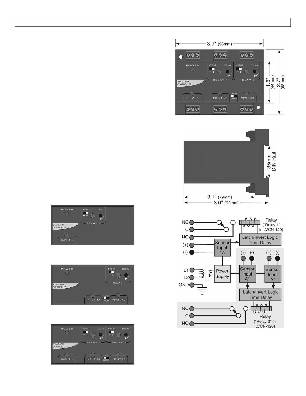
TopView‐AllModels
SideView‐AllModels
LVCN‐140seriesfaceplate:1sensorinput,1relayoutput.
LVCN‐130series
Therelayincludedisalatchingrelay.
LVCN‐120seriesfaceplate:3sensorinput,2relayoutputs.
Onerelayislatchingandtheotherisasingleinputrelay.
faceplate:2sensorinputs,1relayoutput.
InternalControllerLogic
4
Page 5

SAFETYPRECAUTIONS StepThree
AboutThisManual:PLEASEREADTHEENTIREMANUALPRIORTOINSTALLINGORUSINGTHIS PRODUCT.
This manual includes information on three different models of Remote Relay Controllers from OMEGA
ENGINEERING:LVCN‐120,LVCN‐130andLVCN‐140series.Manyaspectsofinstallationandusearesimilar
betweenthethreemodels.Wheretheydiffer,themanualwillnoteit.Pleaserefertothepartnumberon
thecontrolleryouhavepurchasedasyouread.
User’s Responsibility forSafety:OMEGAENGINEERING manufactures several modelsofcontroller, with
differentmountingandswitchingconfigurations.Itistheuser’sresponsibilitytoselectacontrollermodel
that is appropriate for the application, install it properly, perform tests of the installed system, and
maintainallcomponents.
Electrical Shock Hazard:It is possible to contact components on the controller that carry high voltage,
causing serious injury or death.All power tothecontrollerandtherelaycircuit(s)it controls should be
turned OFF prior to working on the controller.If it is necessary to make adjustments during powered
operation,use extremecautionanduseonly insulatedtools.Makingadjustmentstopoweredcontrollers
isnotrecommended.Wiringshouldbeperformedbyqualifiedpersonnelinaccordancewithallapplicable
national,stateandlocalelectricalcodes.
FlammableorExplosiveApplications:TheentireLVCN‐120/‐130/‐140seriesremotemountcontrollers
shouldnotbeusedwithexplosiveorflammableliquids,whichrequireanintrinsicallysafeorexplosion
proofrating.Ifyouareunsureofthesuitabilityofacontrollerforyourinstallation,consultyourOmega
Engineeringrepresentativeforfurtherinformation.
InstallInaDryLocation:Thecontrollerhousingisnotdesignedtobeimmersed.Wheninstalledproperly,
the controller is not designed to be immersed.It should be mounted in such a way that it does not
normallycomeintocontactwithliquid.Refertoanindustryreferencetoensurethatcompoundsthatmay
splashontothecontrollerhousingwillnotdamageit.Suchdamageisnotcoveredbythewarranty.
RelayContactRating:Therelayisratedfora10ampresistiveload.Manyloads(suchasa motorduring
start‐uporincandescentlights)arereactiveandmayhavean inrushcurrentcharacteristicthatmaybe10
to 20 times their steady‐state load rating.The use ofa
yourinstallationifthe10ampratingdoesnotprovideanamplemarginforsuchinrushcurrents.
contact protection circuit may be necessary for
5
Page 6

SAFETYPRECAUTIONS(cont.) StepThree
Make a Fail‐Safe System: Design a fail‐safe system that accommodates the possibility of relay or power
failure.If power is cut off to the controller, it will de‐energize the relay.Make sure that the de‐energized
stateoftherelayisthesafestateinyourprocess.Forexample,ifcontrollerpowerislost,apumpfillingatank
willturnoffifitisconnectedtotheNormallyOpensideoftherelay.
While the internal relay is reliable, over the course of time relay failure is possible in two modes: under a
heavyload thecontactsmaybe“welded”orstuckintothe energizedposition,orcorrosionmaybuildupona
contact so that it will not complete the circuit when it should.In critical applications, redundant backup
systems and alarms must be used in addition to the primary system.Such backup systems should use
differentsensortechnologieswherepossible.
While this manual offers some examples and suggestions to help explain the operation of OMEGA
ENGINEERINGproducts, suchexamplesareforinformationonlyandare notintended asa completeguideto
installinganyspecificsystem.
Components:
LVCN‐140 ‐SingleInputHighorLowRelayController
LVCN‐140‐CE ‐SingleInputHighorLowRelayControllerw/CE
LVCN‐130 ‐DualInputAutomaticFill/EmptyRelayController
LVCN‐130‐CE ‐DualInputAutomaticFill/EmptyRelayControllerw/CE
LVCN‐120‐ThreeInputAutoFill/EmptyRelayControllerwithSingleInputHighorLowRelay
LVCN‐120‐CE‐ThreeInputAutoFill/EmptyRelayControllerwithSingleInputHighorLowRelayw/CE
Owner’sManual
6
Page 7
GETTINGSTARTED StepFour
FeaturesofaSingleInputHighorLowRelay:SingleInputRelays(LVCN‐140series,LVCN‐130serieswithlatch
turned OFF and LVCN‐120 series) are designed to receive a signal from a single liquid sensor.It turns its
internalrelayONor OFF (assetbythe invert switch) in responsetothe presenceofliquid,and changes the
relaystatusbackagainwhenthesensorisdry.
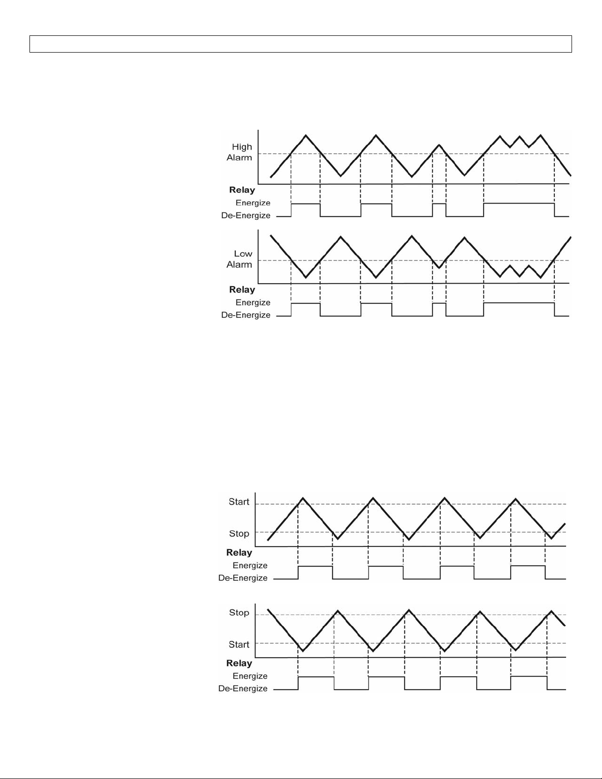
HighAlarm:
Invert is OFF.Relay will
energize when the switch
becomes Wet and will de‐
energize when the switch
becomesDry(outofliquid).
LowAlarm:
InvertisON.Relay
when the switch becomes Dry
(out of liquid) and will de‐
energize when the switch
becomesWet.
willenergize
SingleInputRelaysmaybeusedwithalmostanykindofsensorsignal:currentsensingorcontactclosure.The
relayis asingle pole,double throwtype; thecontrolleddevicecanbe
ornormallyclosedsideoftherelay.Atimedelayfrom0to60secondscanbesetbeforetherelayrespondsto
the sensor input.Typical applications for Single Input Relays are high level or low level switch/alarm
operations(openinga drainvalvewheneverliquidlevel risestoasensorpoint) andleakdetection (sounding
analarmwhenaleakisdetected,etc.).
FeaturesofaDualInput AutomaticFill/EmptyRelay:The DualInput AutomaticFill/EmptyRelay (LVCN‐120
andLVCN‐130seriesonly)isdesignedtoreceivesignals fromtwoliqui dsensors.ItturnsitsinternalrelayON
or OFF (as set by the invertswitch)inresponsetothepresenceofliquidonbothsensors, and changes the
relaystatusbackagainwhenbothsensorsaredry.
AutomaticEmpty:
Latch is ON & Invert is OFF.Relay
will energize when level reaches
high switch (both switches are
wet).Relay will de‐energize when
level is below the bottom switch
(bothswitchesaredry).
AutomaticEmpty:
Latch is ON & Invert is ON.Relay
will energize when level is below
the bottom switch (both switches
are dry).Relay will de‐energize
when level reaches
(bothswitchesarewet).
high switch
connected toeither thenormallyopen
7
Page 8
GETTINGSTARTED(continued) StepFour
TheDualInputAutomaticFill/EmptyRelay maybeusedwithalmostanykindofsensorsignal:currentsensing
orcontactclosure.Therelay is asinglepole, double throw type;thecontrolled device canbeconnected to
eitherthenormally openornormally closedsideofthe relay.Atime delayfrom0 to60seconds canbeset
beforethe relayrespondstothesensorinput.Typicalapplications forDual InputRelays areautomatic filling
(starting fill pump at a low level and stopping pump at a high level) or automatic emptying operations
(openingadrainvalveatahigh
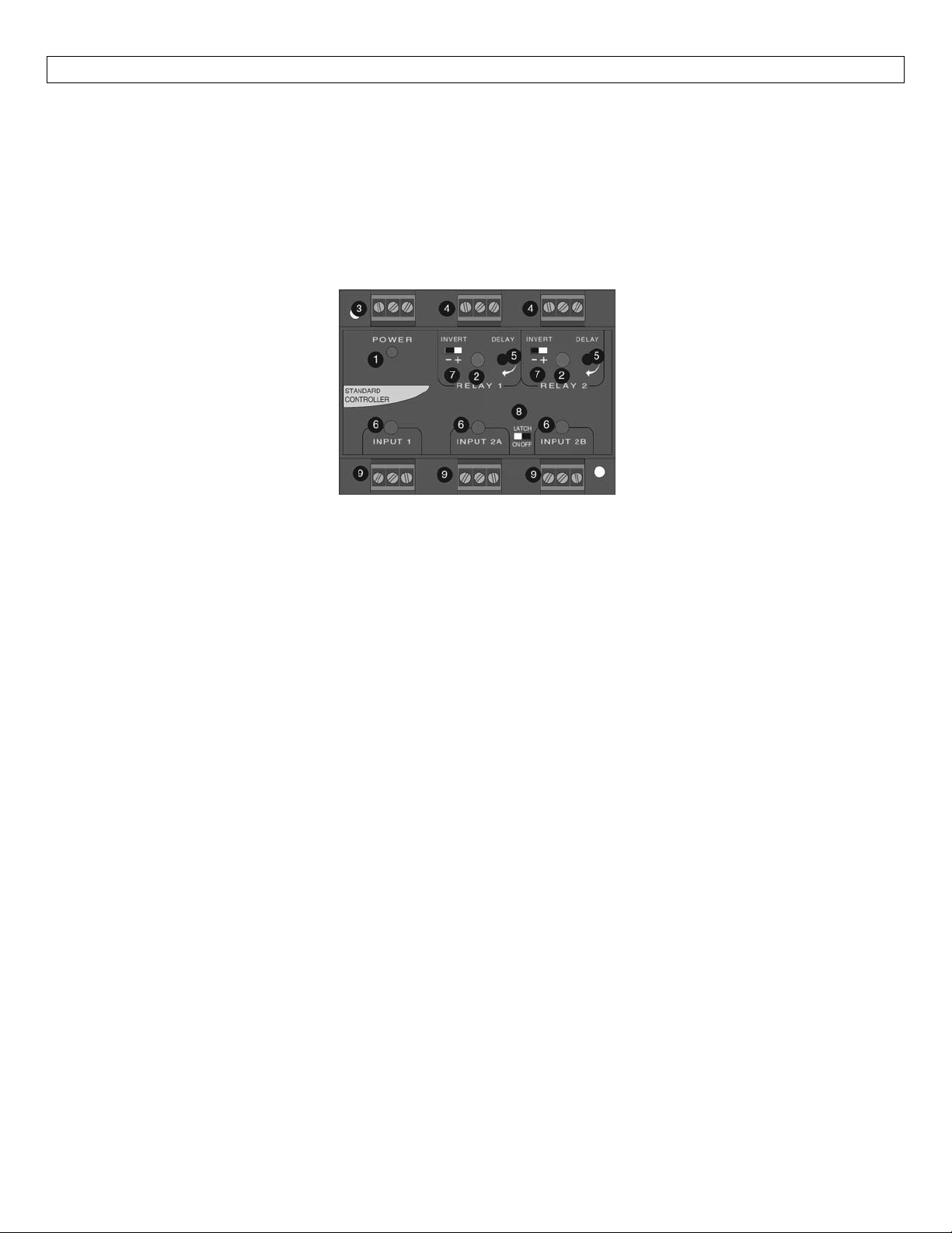
GuidetoControls:Belowisalistingandthelocationofthedifferentcomponentsforthecontroller:
levelandclosingvalveatlowlevel).
1. Powerindicator:ThisgreenLEDlightswhenACpowerisON.
2. Relay indicator: This red LED will light whenever the controller energizes the relay,
properconditionatthesensorinput(s)andafterthetimedelay.
3. ACPowerterminals:Connection of120VACpowertothecontroller.The settingmaybechangedto240
VAC if desired.Thisrequireschanginginternaljumpers; this is covered in the Installation section of the
manual.Polarity(neutralandhot)doesnotmatter.
4. Relayterminals(NC,C,NO):Connectthedeviceyouwishtocontrol(pump,alarmetc.)totheseterminals:
supply totheCOMterminal,andthedeviceto the NO or NC terminal asrequired.Theswitcheddevice
shouldbe anon‐inductive loadof notmore than10 amps;for reactiveloads thecurrentmustbederated
orprotectioncircuitsused.WhentheredLEDisONandtherelayisintheenergizedstate,theNOterminal
willbeclosedandtheNCterminalwillbeopen.
5. Time delay: Use
andswitchbreak.
6. Inputindicators:UsetheseLEDsforindicatingWETorDRYstatusofswitch.WhenswitchisWET,LEDwill
beAmber.WhenswitchisDRY, LEDwill eitherbeGreenforpowered switchesor OFFforreed switches.
Note:PoweredswitchesmaybereversedforWET/OFF,DRY/Amberindication.
7. Invertswitch:Thisswitchreversesthe logicof therelay controlin responsetotheswitch(es):conditions
thatusedtoenergizetherelaywillnowde‐energizetherelayandviceversa.
8. Latch
9. Inputterminals:Connecttheswitchwirestotheseterminals:Notethepolarity:(+)isa13.5VDC,27mA
switch (LVCN‐120 and LVCN‐130 series only):This switch determines how the relay will be
energizedinresponse tothetwosensorinputs.WhenLATCHisOFF,therelayrespondstosensorInputA
only;whenLATCH is ON, therelaywill energize orde‐energizeonlywhen both switches(Aand B) arein
the same condition (both wet or both dry).The relay will remain latched until both switches change
conditions.
powersupply(connectedtotheredwire
from the sensor (connected to the black wire of a OMEGA ENGINEERING level switch).If polarity is
reversed,thesensorswillnotwork.
potentiometer to set delay from 0.15 to 60 seconds.Delay occurs during switch make
ofaOMEGAENGINEERINGlevelswitch),and(‐)isthereturnpath
in response to the
8
Page 9
ELECTRICAL StepFive
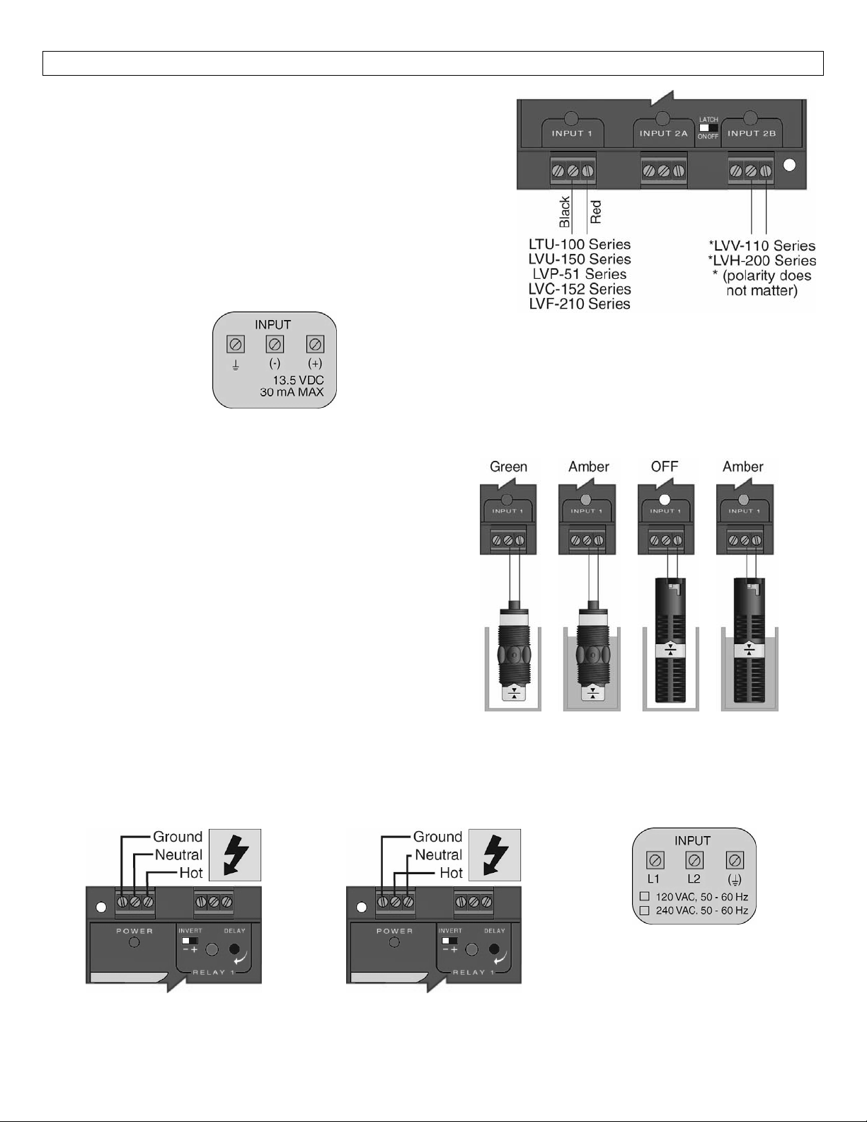
Connecting switches to input terminals:Please note a
difference between OMEGA ENGINEERING powered level
switchesandreed switches.All poweredlevelswitches (series
LTU‐100, LVU‐150, LVP‐51, LVC‐152 & LVF‐210 series) will be
wired withtheRedwireto the (+) terminaland the Black wire
the(‐)terminal.OMEGAENGINEERINGreedswitches(series
to
LVV‐110 & LVH‐200 series) will have a particular wiring based
uponpartnumber.Seetheillustrationbelowtoindicatewiring
foryourswitch.Note:theShieldwire willbeusedonlyforlong
cablerunsorwhereexcessiveelectricalnoiseispresent.
* LVV‐110 series can be wired using the
White and Black wires for NO operations
or the Red and Black wires for NC
LED Indication:Use LED's located above the input
terminalstoindicatewhethertheswitchisinawetor
dry state.
dry and Amber indicates wet.With reed switches,
Amberindicates wetandnoLED indicatesdry.Note:
reed switches may be wired in reverse so that wet
indicatesdryandAmberindicatesdry.
With powered switches, Green indicates
operations.
PoweredSwitches ReedSwitches
VAC Power Input Wiring:Observe the POWER SUPPLY label on the LVCN‐120/‐130/‐140 series.The label
identifies thepowerrequirement (120or240VAC) and the terminal wiring.Note: Polaritydoesnotmatter
withtheACinputterminal.
9
Page 10
ELECTRICAL(continued) StepFive
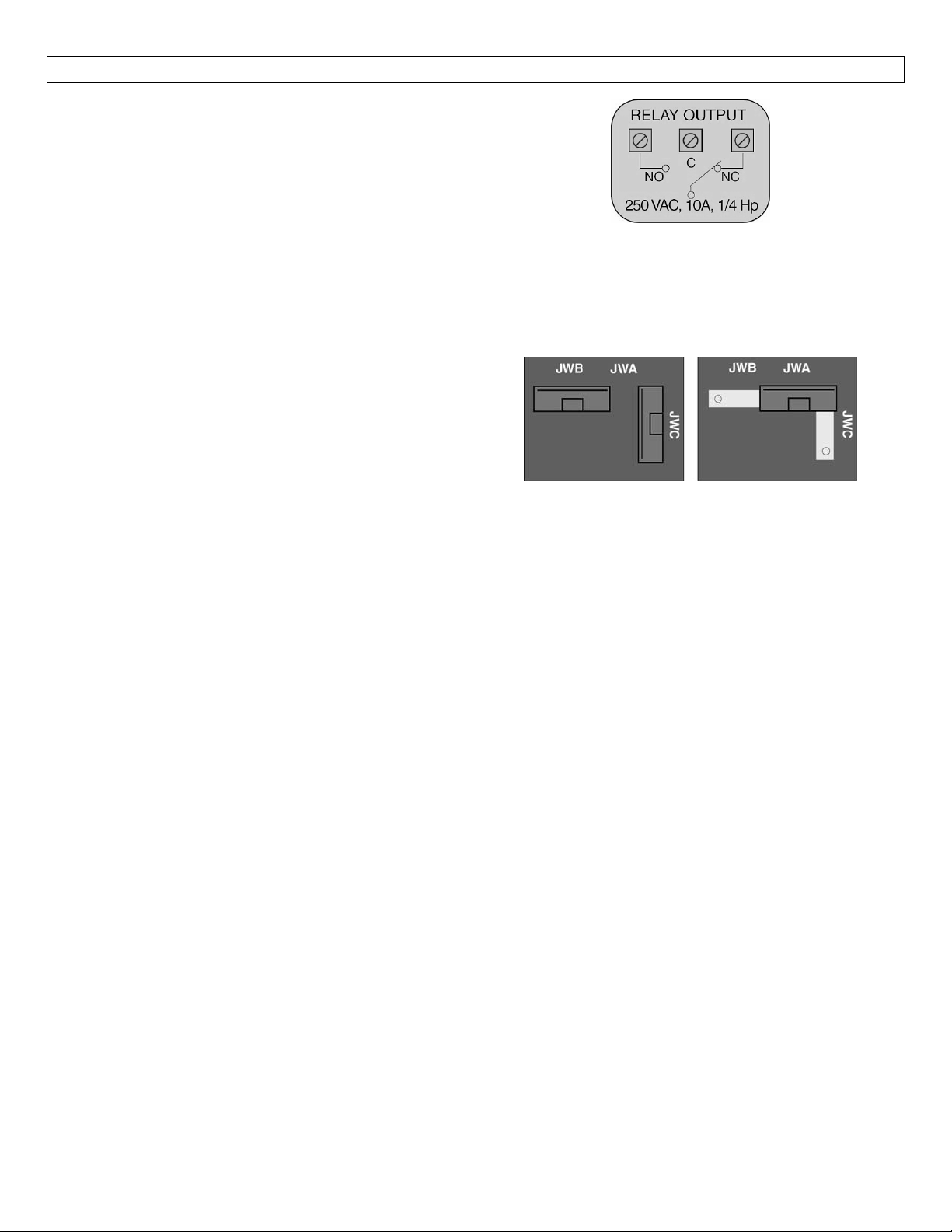
RelayInput Wiring:Therelayisasingle pole,double
throw type rated at 250 Volts AC, 10 Amps, 1/4 Hp.
The two terminal NO and NC (normally open and
normallyclosed)willbeusedindifferentapplications.
Remember thatthe"normal"state is when the relay
coilisde‐energizedandtheRedrelay LEDis Off/de‐
energized.
Changingfrom120to240VAC:
1. Remove the back panel of the controller and
gently slide the printed circuit board from the
housing.UsecautionwhenremovingthePCB.
2. LocatedjumpersJW1,JW2andJW3onthePCB.
3. Tochangeto240VAC,remove jumpersfromJW1
andJW2andplaceasinglejumperacrossJW3.To
changeto120VAC,removejumperJW3andplace
jumpersacrossJW1andJW2.
4. Gently return PCB into housing and replace back
panel.
120VAC 240VAC
Configuration Configuration
10
Page 11
INSTALLATION StepSix
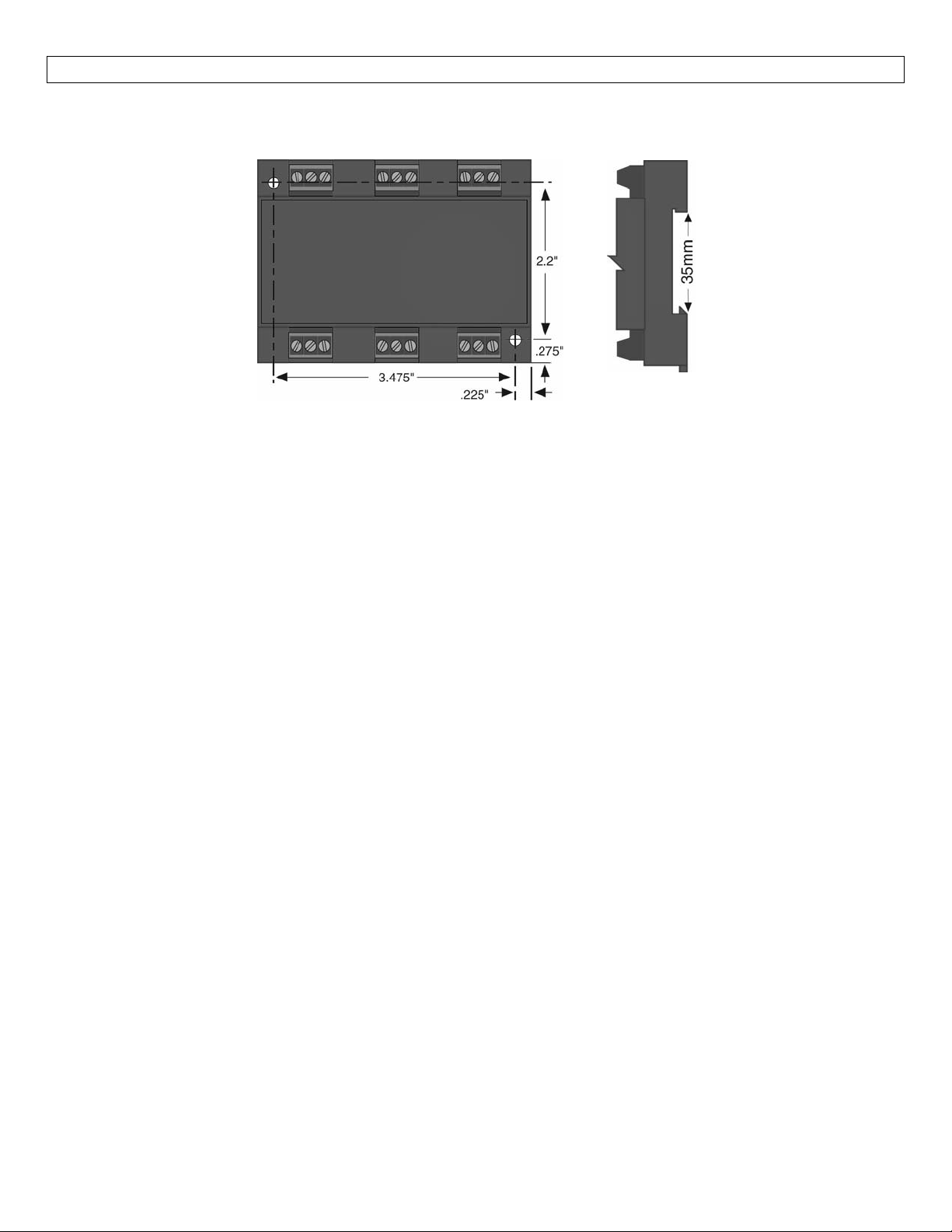
PanelDINRailMounting:The controller maybemounted by eitheraback panel usingtwoscrews through
mountingholeslocatedatthecornersofthecontrollerorbysnappingthecontrolleron35mmDINRail.
Note:Alwaysinstallthecontrollerinalocationwhereitdoesnotcomeintocontactwithliquid.
11
Page 12

APPLICATIONEXAMPLES StepSeven
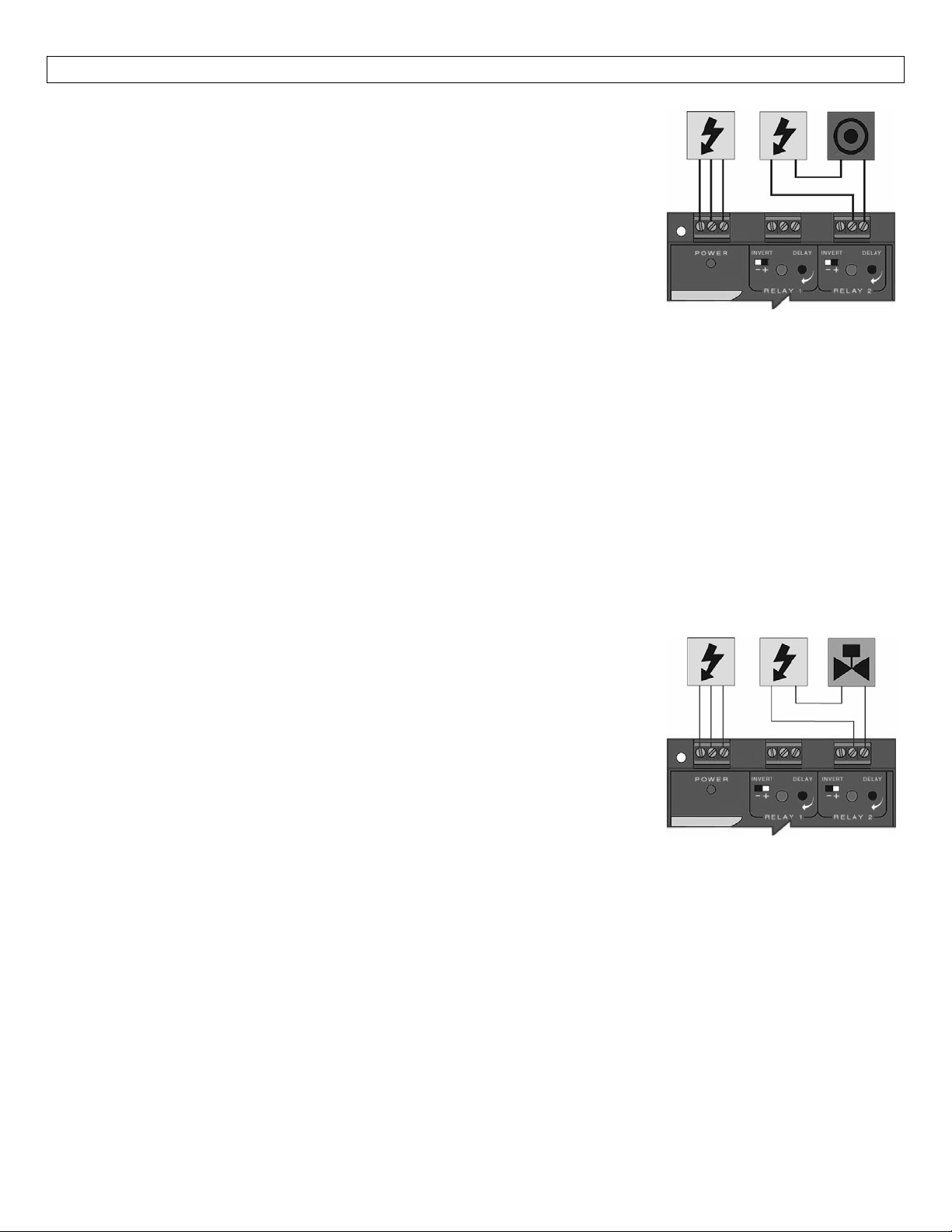
LowLevelAlarm:Thegoal istomakesurethattheliquidlevel doesnotfallbelowacertainpoint.Ifit does,
analarmissupposedtosound,alertingtheoperatorofalowlevelcondition.
Ifpowerisaccidentallycuttothe controller,thesensor'sabilitytonotifytheoperatorofalowlevelcondition
couldbelost.Thesystemmustalerttheoperatornotonlytolowliquidlevel,buttocontrollerpowerloss.
To do this, connect the hot lead of the alarm to the NC side of the relay
terminalofthecontroller.Ifpowerislost,therelaywill bede‐energized,and
the alarm will sound (if there is still power to the alarm circuit itself).The
alarm circuit should have a non‐interruptible power supply or some other
indicatororbackupalarmtowarnofapowerfailureinthealarmcircuit.
In this application, the normal status if the sensor at the bottom if the tank
will be wet, and the relay will be energized holding the alarm circuit open.
Both the relay LED and the Input LED will be on simultaneously, so for this
application,InvertshouldbesettotheOFFposition.
HighLevelAlarm:Inthesame manor,thissystem canbeusedtosound analarmwhen fluidreaches ahigh
level, with just a change in the location of the sensor and the setting of the
Invertswitch.
The alarm isstillconnectedtothe NC side of the relay to allow for a power
failurealarm.
The sensor is normally dry.In this condition, we want the relay to be
energized so thealarmdoesnotsound: i.e., the Red relay LED should be on
whenevertheInputLEDisAmber.SoweturnInvertOn.Ifthefluidlevelrises
tothehigh sensor point,thesensor goes on,therelay de‐energizes,andthe
alarmsounds.
LEDIndication:Todeterminewhethertheswitchisinawetordrystate,observetheLED'slocatedabovethe
inputterminals.Withpowered switches,Green indicatesdryand Amber
Amber indicates wet and no LED indicates dry.Note: reed switches maybe wired in reverse so that wet
indicatesdryandAmberindicatesdry.
indicateswet.Withreedswitches,
12
Page 13
APPLICATIONEXAMPLES(cont.) StepSeven
AutomaticFill:Thissystem consistsofa tankwitha high levelsensor, a low
levelsensor,andapumpthatiscontrolledbythecontroller.Partofaproper
fail‐safe design for this particular system is that if power is lost to the
controller for any reason, the pump filling the tank must be turned off.
Therefore,weconnectthepumptotheNOsideoftherelay.Whentherelay
isenergized,the pump will turnonand fill the tank.Therelayindicatorwill
corresponddirectlytotheON/OFFstatusofthepump.
NOTE:Ifthepump motorloadexceeds theratingof thecontroller’srelay, a
stepperrelayofhighercapacitymustbeusedaspartofthesystemdesign.
DeterminingthesettingsofLATCHandINVERT:Thisisthewaythesystemmustoperate:
Whenboththehighandlowsensorsaredry,thepumpshouldturnon,startingtofillthetank.
Whenthelowsensorgetswet,thepumpshouldstayon.
Whenthehighsensorgetswet,thepumpshouldturnoff.
Latch:Inanytwo‐sensorcontrolsystem,LATCHmustbeON.
Invert:Referringtothe logicchart inStepNine, welookfor thesettingthatwillde‐energize therelay(start
thepump)whenbothinputsarewet(AmberLEDs).Inthissystem,InvertshouldbeON.
DeterminingAorBinputconnections:WhenLATCHisON, thereisnoeffectivedifferencebetweenInput A
andB,sincebothsensorsmusthavethesamesignalinorderforstatustochange.Whenwiringanytwo‐input
relaysection,theonlyconsiderationforhookingaparticularsensortoAorBisifLATCHwillbeOFF.
Automatic Empty:Note that similar system logic can be used for an
automaticemptyoperationsimplybycontrollingapumpthatpumpsfluidout
of the tank instead of into it.However, note the importance of fail‐safe
design.If the tank is being passively filled, and a pump must be used to
activelyempty it,apowerfailuretoeitherthecontrollerorthepumpcircuits
willcauseoverflow.
Alternatively,anelectrically‐controlleddrainvalvecouldbeused.Inthiscase,
the valve should be a type that will automatically open if power is lost; in
other words, power must be used to hold it closed.The valve would be
connectedto
thepowerthatwasholding itshut, andfluidwilldrainfrom thetank intosomeothersafecontainment until
power is restored. In this system, whenever the red relay LED of the controller is ON, the drain is closed,
allowingfluidtorise.
Inthiscase, Invertshould beON:when bothsensorsare wet,therelay de‐energizes,the switchtothe valve
opens,andthetankwilldrain.
theNOsideoftherelay—ifpowerislosttothecontroller,therelayde‐energizes,thevalveloses
13
Page 14
APPENDIX StepEight
ControllerLogic:Pleaseusethefollowingguidetounderstandtheoperationofthecontrollers.
1. PowerLED:MakesuretheGreenpowerLEDisONwhenpowerissuppliedtothecontroller.
2. Input LED(s):Theinput LED(s)on thecontrollerwillbeAmberwhentheswitch(es)is/are wetand Green
orOFFwhentheswitch(es)is/aredry.IftheLED'sarenotswitchingtheinputLED,testthelevelswitch.
3. Single‐InputRelays:WhentheinputLEDturnOFFandON,therelayLEDwillalsoswitch.WithinvertOFF,
therelayLEDwillbeONwhentheinputLEDisONandOFFwhentheinputLEDisOFF.WithinvertON,the
relayLEDwillbeOFFwhentheinputLEDisONandONwhentheinputLEDisOFF.
4. Dual‐Input (latching) Relays:When both inputs are wet (Amber LED's ON), the relay will be energized
(Red LED ON).After that, if one switch becomesdry, the relay will remain energized.Only when both
switches are dry (both amber LED's OFF) will the controller de‐energize the relay.The relay will not
energizeagainuntilbothswitchesarewet.SeetheRelayLatchLogicChartbelowforfurtherexplanation.
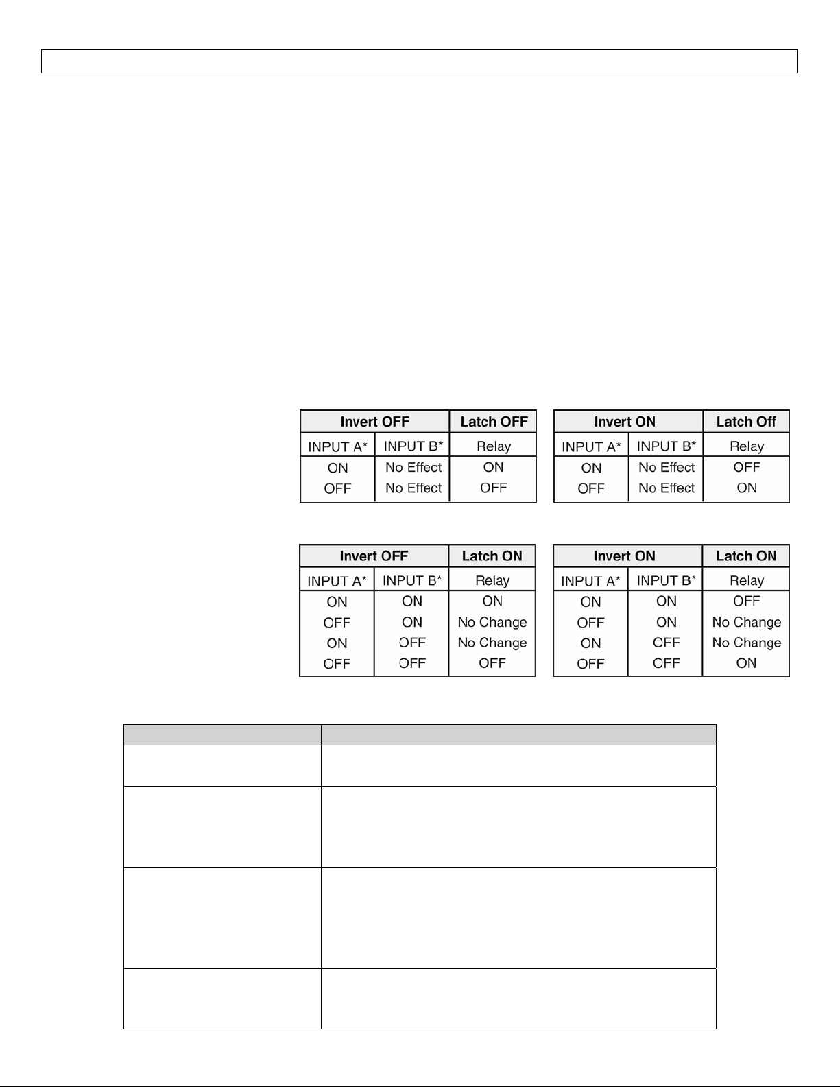
RelayLatchLogicTable(latchingrelaysonly):Therelaycaneitherbeanindependentrelay(highorlowlevel
alarm)or canbea latching relay (automatic fillorempty)with latch ON.With LatchOFF,therelay will only
respondtotheINPUTAsetting.INPUTBwillbeignored.
With Latch ON, the relay will
actuate when INPUT A and INPUT
B are in the same condition.The
relay will not change its condition
until both inputs reverse their
state.
Caution:Some sensors
(particularly buoyancy sensors)
may have their own inverting
capability (wired NO or NC).This
will change the logic of the invert
switch.Checkyoursystemdesign.
Troubleshooting
PROBLEM SOLUTION
Relayswitchesonlyfrom
inputA(ignoresinputB)
LevelreachesalarmON,
butrelayisOFF.
PumporValveissupposed
tostop,butitdoesnot.
Controllerispowered,but
nothinghappens.
LatchisturnedOFF.FlipthelatchswitchtoturnON.
First, check to make sure the input LED is ON.If not,
checkwiringtosensor.
Second, checkstatusofRelayLED.Ifincorrect, flip the
Invertswitchtochangetherelaystate.
First,checktomakesure theinput LEDsareboth inthe
satestate(bothONorbothOFF).Ifnot,checkwiringto
sensoreachsensor.
Second, checkstatusofRelayLED.Ifincorrect, flip the
Invertswitchto
First check the Power LED to make sure it is Green.If
not,checkthewiring,powerandmakesuretheterminal
isseatedcorrectlyoverthe6‐pins.
changetherelaystate.
14
Page 15

15
Page 16

16
 Loading...