

Page 1
2
1
Page 2

Page 3

INTRODUCTION/TABLEOFCONTENTS StepOne
Offeredinsmall and large sizes, the compact junction box is ideal for sensorwiringandconduittermination.
The junction box isuniversally compatible withour level switch,flow switch and fittingproducts.The small
enclosure(LVCN‐12series)has6polesandistypicallyusedwithasinglelevelorflowswitchsensor.Thelarge
enclosure(LVCN‐11series)has12polesformultiplelevelswitchesandistypicallyusedwithSmartTrak.
Features
PolypropyleneenclosureratedNEMA4Xwith300°conduitswivelbase.
CompatiblewithOmegaEngineeringsensors,installationfittingsandalarms.
Removableterminalstripswithupperandlowerscrewpoles.
Offeredinlargeandsmallsizesforsingleormulti‐pointinstallations.
TableofContents
Specifications:.........................................................................................................................................................4
Dimensions:.............................................................................................................................................................4
SafetyPrecautions:.................................................................................................................................................5
MakeaFail‐SafeSystem:............................................................................................................................6
Components:...............................................................................................................................................6
Installation..............................................................................................................................................................7
MountingtoaSensor:...............................................................................................................................7
MountingtoaLVM‐10seriesorLVM‐51series:.......................................................................................8
3
Page 4
SPECIFICATIONS/DIMENSIONS StepTwo
Sensorinput: LVCN‐11:1‐4sensors
LVCN‐12:1‐2sensors
Terminalstrip: LVCN‐11:12polesocket
LVCN‐12:6polesocket
Max.currentcapacity: 26Amps
Max.voltage: 380V
Wirestripping: 0.5mmor0.2”
Terminalscrewtorque:3.5in‐lbs.
Wiregauge: 22‐14AWGCu(copper)
Enclosurerating: NEMA4X(IP65)
Enclosurematerial: Polypropylene(U.L.94VO)
Enclosurerotation: 300°swivelbase
Temperaturerange.: F:‐40°to158°
C:‐40°to70°
Conduitentrance: Single,½”NPT
Mountingconnection: Single,¾”NPT
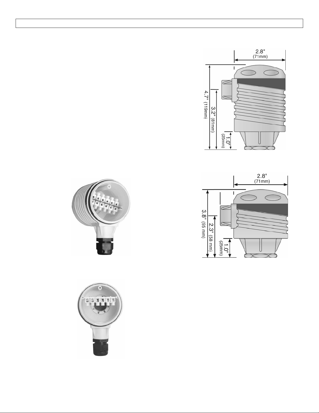
TopVieww/oCap
LVCN‐11Series
SideView
LVCN‐11Series
SideView
LVCN‐12Series
TopVieww/oCap
LVCN‐12Series
4
Page 5

SAFETYPRECAUTIONS StepThree
AboutThis Manual:PLEASEREADTHE ENTIREMANUALPRIOR TOINSTALLINGORUSING THISPRODUCT.
Thismanualincludesinformationon the Compact Junction Boxes from OmegaEngineering: LVCN‐11 and
LVCN‐12Series.Pleaserefertothepartnumberlocatedonthelabeltoverifytheexactmodelwhichyou
havepurchased.Manyaspectsofinstallationandusearesimilarbetweenmodels.
User’s Responsibility for Safety:OMEGAENGINEERINGmanufactures several modelsofcontroller, with
different mounting and switching configurations.It is the user’s responsibility to select a junction box
modelthatisappropriatefortheapplication,installitproperly, perform testsoftheinstalledsystem, and
maintainallcomponents.
ElectricalShock Hazard:Itispossibletocontact componentsonthejunctionbox that carryhighvoltage,
causingseriousinjuryordeath.AllpowertothecircuitsintheterminalstripshouldbeturnedOFFpriorto
workingon the controller.Ifitis necessary tomakeadjustments during poweredoperation,useextreme
caution and use only insulated tools.Making adjustments to powered controllers is not recommended.
Wiring should be performed by qualified personnel in accordance with all applicable national, state and
localelectricalcodes.
Flammable or Explosive Applications: Sensor mount controllers should not be used with explosive or
flammable liquids, which require an intrinsically safe or explosion proof rating.If you are unsure of the
suitabilityof a controller for yourinstallation,consultyourOmega Engineering representative for further
information.
InstallIna Dry Location:While the compact junction boxisliquid‐resistantwheninstalledproperly, it is
not designed tobe immersed.It should be mountedin such a way thatit does not normally come into
contactwithfluid.ItshousingismadeoutofPP(propylene).Refertoanindustryreferencetoensurethat
compoundsthatmay splash onto the controller housing willnot damageit.Such damageisnotcovered
bythewarranty.
Application:The LVCN‐11 series junction box is commonly used for the local termination of multiple
switches installed on a LVM‐10 series mounting system.The LVCN‐12 series junction box is commonly
used for the local termination of a single level or flow switch.Combine these junction boxes with any
switchorfittingassemblytocompleteyourapplication.
5
Page 6

SAFETYPRECAUTIONS(cont.) StepThree
Make a Fail‐Safe System: Design a fail‐safe system that accommodates the possibility of relay or power
failure.If power is cut off to the controller, it will de‐energize the relay.Make sure that the de‐energized
stateoftherelayisthesafestateinyourprocess.Forexample,ifcontrollerpowerislost,apumpfillingatank
willturnoffifitisconnectedtotheNormallyOpensideoftherelay.
Allpowertothesystemmustbeturnedoffbeforeinstallingthehousing.
Important:Donotstripmorethat0.25”ofinsulationfromanywirethatwillbeconnectedtotheterminal
strip.Longer un‐insulated wire may contact theterminal strip panel, causing a shortcircuit leading toa
systemfailure.
All wiring betweena controller and sensor(s) should be inconduit.The power entrance of the terminal
strip housing is a standard ½” NPT female fitting that will attach to a standard electrical conduit, either
plastic or metal, as specified by local codes.Keep in mind that the housing may have to be unscrewed
fromthesens
enoughslackforeasyaccessisrecommended.
Usecaution when installing the conduit.Excessivetighteningmaybreak the fitting.Such damage isnot
coveredbythewarranty.
orforperiodiccleaningofthe sensor.For this reason the use of flexible conduit, providing
In some cases, additional user‐provided components may need to be attached to the terminals.If so,
make sure that both wires and/or components entering the terminal are secure after the screws are
tightened.
Components:
LVCN‐11 ‐Multi‐Input(12‐pole)JunctionBox,NPTThread
LVCN‐12 ‐Single‐Input(6‐pole)JunctionBox,NPTThread
Owner’sManual
6
Page 7
INSTALLATION StepFour
MountingonaSensor:Thefollowingprocedureshouldbeusedwhenmountingthejunctionboxdirectlyona
sensor.Allpowertothesystemmustbeoffbeforeinstallingthejunctionbox.
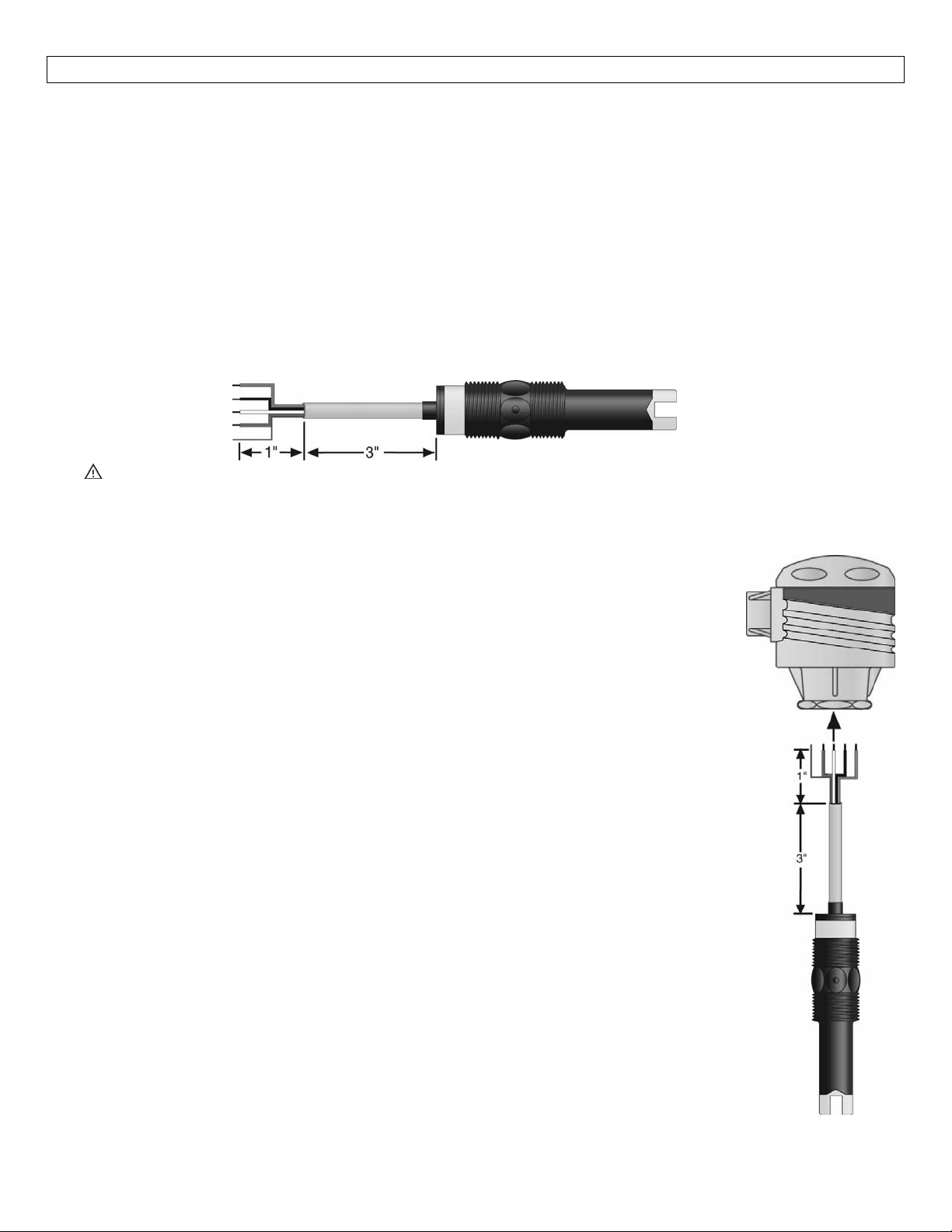
1. Preparethesensor:Thefollowinginstructionsassumethesensoris alreadymountedinaposition on
itstank or fitting (as describedinthe sensor manual).Note that becausetheinsulation jacket of the
sensorislessflexible than most (to ensurechemicalcompatibility),itisimportant that you follow the
instructionsexactly.
a. Cutthewire4‐1/4”fromthetopofthesensor.
b. Using a10gaugewirestripper,strip the whiteouterlayerofinsulationfrom the last 1‐1/4” of
thesensorwire.Trimoffanddiscardtheexposedfoilshieldflushwiththeinsulationjacket.In
longcableruns,donotcutoffthedrainwire.
c. Usinga20gaugewirestripper,stripthelast¼”ofinsulationfromthesignalwires.
Important:Donotstripmorethan0.2”(5mm)ofinsulationfromanywirethatwillbeconnectedtothe
terminal strip.Longer insulated wire may contact the terminal strip panel, causing a short circuit
leadingtoasystemfailure.
2. Position the junction box on the sensor:To make the mounting and wiring easier, you must first
removetheterminalstripfromthejunctionbox.
a. Unscrewthelidofthejunctionbox.
b. Gentlytipthejunction boxtoslideouttheterminalstrippanel,andplace
itaside.
c. Threadthepre‐trimmedsensorwiresthroughthe¾”NPTentrancetothe
junctionbox,andplacethejunctionboxinpositionoverthesensor.
d. Being careful not to cross the threads, screw the junction box on the
sensor.Stopwhen thecapofthe sensor becomesflushwiththe bottom
wallofthejunctionbox,orwhenthe½”powerconduitentranceisinthe
desiredlocation.
3. Connectthesensorinputwires:
a. Routethesensor‐wiresoit stays as close to the housingas possible, but
donot bendthewiresharply atthecap ofthesensor.(Iftheinstallation
allows,youmayrotate the junction box and/orthesensor until the wire
outletofthesensorisinthebestposition.)
b. Position the terminal strip panel in the housing aligned with the two
channelsdesignedtohold it.Donotinsertthepanelalltheway intothe
housing,butletitrestonthetopofthehousingtofacilitatethewiring.
c. Using a smallscrewdriver,loosentheterminal screws.Insert the sensor
wiresintotheholeonthelowersideoftheterminalstrip,andtightenthe
terminalscrews.
4. Mechanicalconnectionto conduit:Allwiringbetweena controller and sensors
should be inconduit.The power entranceof the junctionbox is a standard ½”
NPTfemalefittingthat willattachtostandardelectricalconduit,either plasticor
metal,asspecifiedbylocalcodes.Keepinmindthatthehousingmayhavetobe
unscrewed from the sensor for periodic cleaning of the sensor.
conduit,providingenoughslackforeasyaccessisrecommended.
For this reason the use of flexible
7
Page 8
INSTALLATION(continued) StepFour
5. Connecttheextensionwiring:
Beforemakingconnections,makesureallpowertothesystem(controller,motor,valve,alarm,etc.)
isOFFwithasafetylockoutonthecircuitbreaker.
a. Theextensionwiringtosensorsshouldbeofthesametypeasthesensors.Iftherunislong, it
mayneedtobeaslightlythickergaugesotheseriesresistanceiskelpwithinallowablelimits.
b. Threadtheextensionwiringthroughthepowerconduitentranceofthehousing.
c. Strip¼”oftheinsulationfromtheendsofthewires.
d. Loosentheupperterminalscrews.Inserttheextensionwiresintothecorrespondingterminals,
matchingthesensorwires.
e. Tightentheterminalscrews.
f. Slidetheterminalstrippanel back into the housing, making sure it is in the groveprovidedon
eachsideofthehousing.Thepanel“floats”inthehousing,heldinpositionbythewiring.
g. Screwthelidofthehousingbackon.
Note:In some cases, additional user‐provided components mayneedtobe attached to the terminals.If
so, make sure that both wiresand/or components enteringthe terminal are secure after thescrews are
tightened.
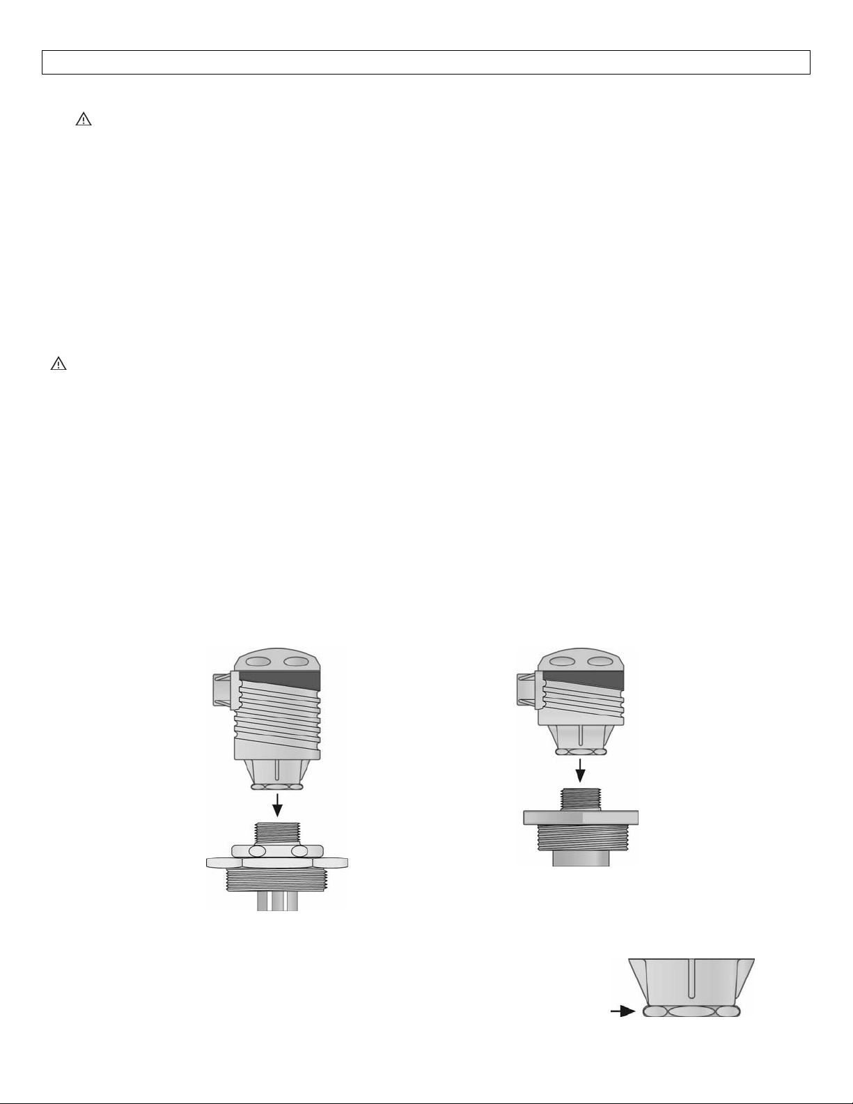
MountingonaLVM‐10seriesorLVM‐51series:AterminalstripmaybemounteddirectlyonaLVM‐10series
or LVM‐51 series mounting system.The only differenc
seriesor directly ona sensor is inthe length of thewiringfrom the sensor(s).Assumingthateach sensor is
already mounted in position, cut the sensor wires to the length approximately 1‐1/2” above the top of the
housing.However,besuretomake allowances when cutting the sensor leadsfor futureadjustments to the
sensorposition.
e between mounting on a LVM‐10 series, a LVM‐51
MountingtoLVM‐10Series
MountingSystem
Note:Alwaystightenthecontrollerfromthewrenchflatlocatedonthe
swivelbase.Nevertightenfromthebodyofthecontroller.
MountingtoLVM‐51Series
MountingSystem
8
Page 9

9
Page 10

10
Page 11

11
Page 12

12
 Loading...