

Page 1
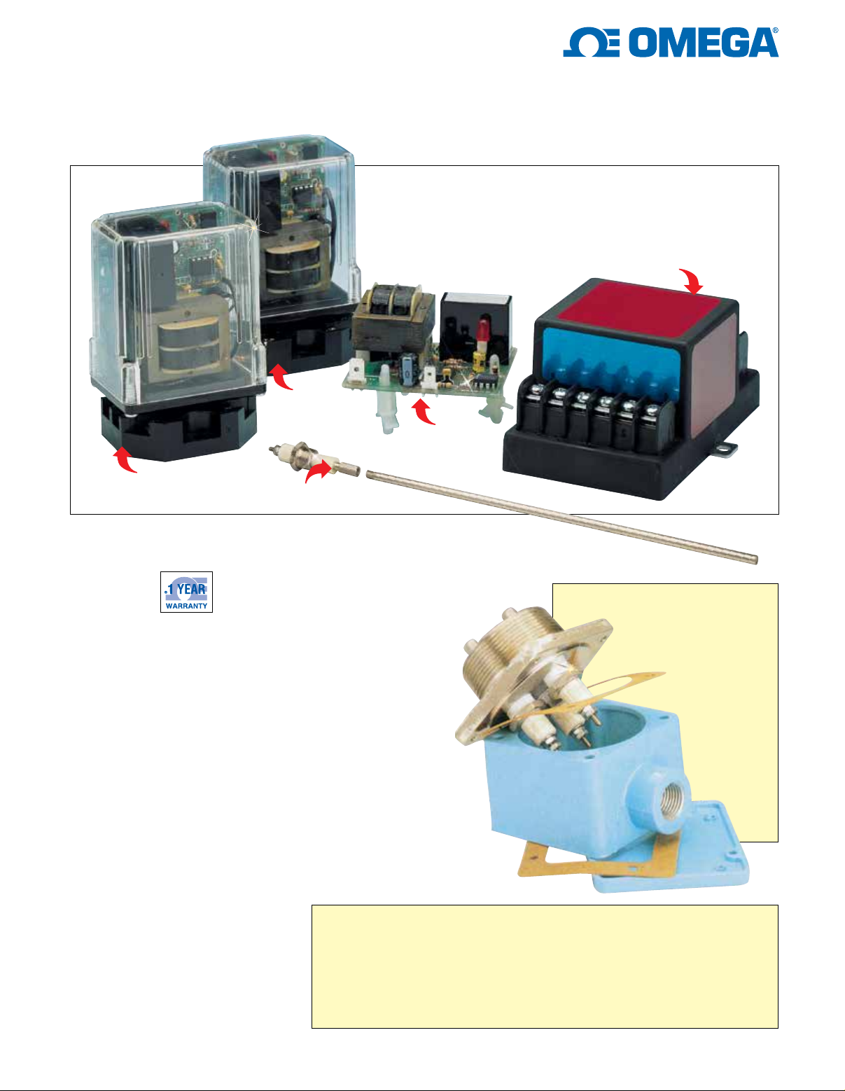
LOW-COST CONDUCTIVITY
LEVEL SWITCH SYSTEMS
For Liquids Only
All products shown
smaller than actual size.
LVC512
LVC521
LVC551
LVC511
LVC-S3 holder
LVC Series
U No Moving Parts
for Long Life
U Wide Chemical
Compatibility
U Works for
Conductive Liquids
The LVC500 Series electronic level
controls should be used whenever a
liquid level needs to be maintained,
such as pumping down an industrial
sump, or indicated, such as a
holding tank high-level alarm. A
system consists of 3 components:
(1) cut-to-length threaded electrode
rods; (2) single or multi-electrode
holder; (3) remote electronic module(s).
The LVC500 Series operates on
a simple conductance principle
whereby a small electrical current
is passed through the conductive
liquid between 2 electrodes or an
electrode and a metallic tank wall.
For applications that require a
separate start and stop point,
a single control module, plus
2 electrodes and a tank reference,
is required. When several
applications or levels are necessary
within a single tank, an
electrode is needed for
each level (plus tank
reference), plus a
multi-electrode holder
and a control module
for each differential or
single-level application.
Typically, potable
water, condensate,
acids, and waterbased chemicals (inorganic
chemicals) have sufficient
conductivity. Non-aqueous
liquids, such as oils and
other hydrocarbons, cannot
be measured.
Always treat hazardous areas with respect! If the electrodes or float switch is located in
a hazardous area, an intrinsically safe control module must be used. Intrinsically safe
controls must be installed by experienced personnel familiar with intrinsic safety wiring, and
installation must be in accordance with the National Electrical Code (NEC). The control must
be mounted in a non-hazardous location with the wiring to the level probes or float switch
going into the hazardous atmosphere. Intrinsically safe wiring must be separated from
non-intrinsically safe wiring, and the length of your 14 or 16 gage copper wire must not
exceed the specifications listed in the current installation manual. Consult your local
electrical code inspector for further details.
Note:
LVC-E11 electrode
LVC-N3-SS, SS threaded
multi-electrode assembly
shown smaller than
actual size.
1
Page 2
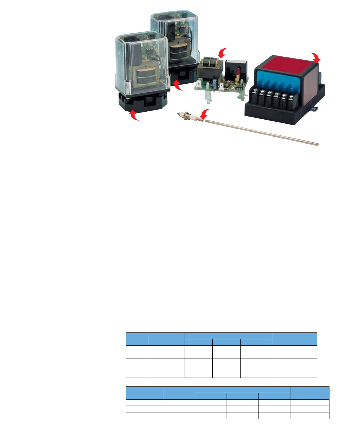
Electronics Modules
Mounting Assemblies
All products shown
smaller than actual size.
U SPDT Relay Output
U Fully Field Selectable
U Transparent Case for
Viewing Relay Status
• Low-voltage probe circuit
• SPDT relay output
• Interface to pumps, valves,
or alarm systems
• Field-selectable latching/
non-latching operation
• Field-selectable high/low alarm,
pump-up/pump-down
LVC510 Series:
• See-through Lexan® case for
viewing relay status LED
• Plug-in module, socket included
• Screw terminal connections
for easy wiring
LVC512 Model:
• Field-settable sensitivity to match
a variety of liquids
• Required for distilled water
(1 MΩ max)
LVC521 Model:
• Open circuit board construction
• Low cost, OEM style
• Spade terminal connections
• Designed to mount on
1
⁄16"
backplate with supplied
plastic standoffs
• Relay status LED
LVC550 Series:
• Intrinsically safe
• Approved for Class I and II,
Divi sion 1, Groups A through G
• 8 A relay output
• LVC551: FM approved
LVC552: UL approved
• Can be used with any
non-powered switch closure
Electronics Operation Direct
Mode Single-Level Service:
Single-Level Service:
For high or low alarms or cutoffs.
When the liquid rises to the
electrode on terminal H, the control
energizes, changing the state of the
load contacts. The control remains
energized until the liquid level
recedes below electrode on
terminal H. The control then
de-energizes, returning load
contacts to original state.
LVC512
LVC511
Differential Service:
For fill or drain applications. When
the liquid rises to the electrode on
terminal H, the control energizes,
changing the state of the load
contacts. The control remains
energized until the liquid level
recedes below electrode on
terminal L. The control then deenergizes, returning load contacts
to original state.
Inverse Mode:
Control energizes with power,
changing the state of the load
contacts. All other responses are
the opposite of the response given
by direct-mode operation. Inverse
mode is normally used for pump-up
or high-level alarm applications.
SPECIFICATIONS
Supply Voltage: 102 to 132 Vac
(110 to 132 Vac for LVC552), 50/60 Hz
standard; 240 and 24 Vac optional)
Ambient Temperature:
-40 to 65°C (-40 to 150°F)
Switch-Point Hysteresis:
1.6 mm (±
Relay Time Delay:
rising level
See chart below for additional information.
Electronic Modules
LVC
Model
511
512
521
551
552
Multiple Electrode Assemblies
LVC Model
NX-BR/FX-BR
NX-BR/FX-BR
NX-BR/FX-BR
1
⁄16")
Consumption
1
⁄2 second delay on
Power
4.5 W 88.9 (3.5) 50.8 (2) 58.7 (2.31) 487 (20)
4.5 W 88.9 (3.5) 63.5 (2.5) 66.7 (2.62) 487 (20)
4.5 W 34.9 (1.37) 63.5 (2.5) 55.6 (2.19) 487 (20)
4.0 W 54 (2.12) 85.7 (3.37) 111.2 (4.18) 765 (27)
1.7 W 54 (2.12) 85.7 (3.37) 111.2 (4.18) 765 (27)
No. of
Electrodes
1 57.2 (2.25) 57.2 (2.25) 57.2 (2.25)
2 to 4 82.6 (3.25) 82.6 (3.25) 60.4 (2.37)
5 to 7 101.6 (4.0) 101.6 (4.0) 63.5 (2.5)
Dimensions: mm (inch) Shipping Weight
H W L
Housing Dimensions: mm (inch)
H W L
LVC521
LVC-S3
holder
LVC-E11 electrode
MOUNTING ASSEMBLIES
Single Electrode:
The LVC-S Series comprises single
electrode holders with exposed
connection. UL-approved rubber boots
are available for connection protection.
Shipping Weight:
LVC-S unit, 170 g (6 oz)
Overall Length: 82.6 mm (3.25")
Multiple Electrodes:
The LVC-N and LVC-F mounting
assemblies feature a gasketed,
epoxy-coated, die-cast aluminum
junction box, and include the proper
number of electrode holders.
See chart below for additional information.
Electrodes
The LVC-E electrodes come standard
in 316 SS, but are available in a wide
range of materials. Electrodes thread
into couplings on LVC-S, LVC-N, and
LVC-F mounting assemblies.
Electrode Diameter: 6.35 mm (1⁄4");
1
⁄4" thread length
Electrode Weight:
0.25 g/mm (0.167 lb/ft)
LVC551
g (oz)
Housing
Conduit Size
1
⁄2 NPT
1
⁄2 NPT
3
⁄4 NPT
2
Page 3
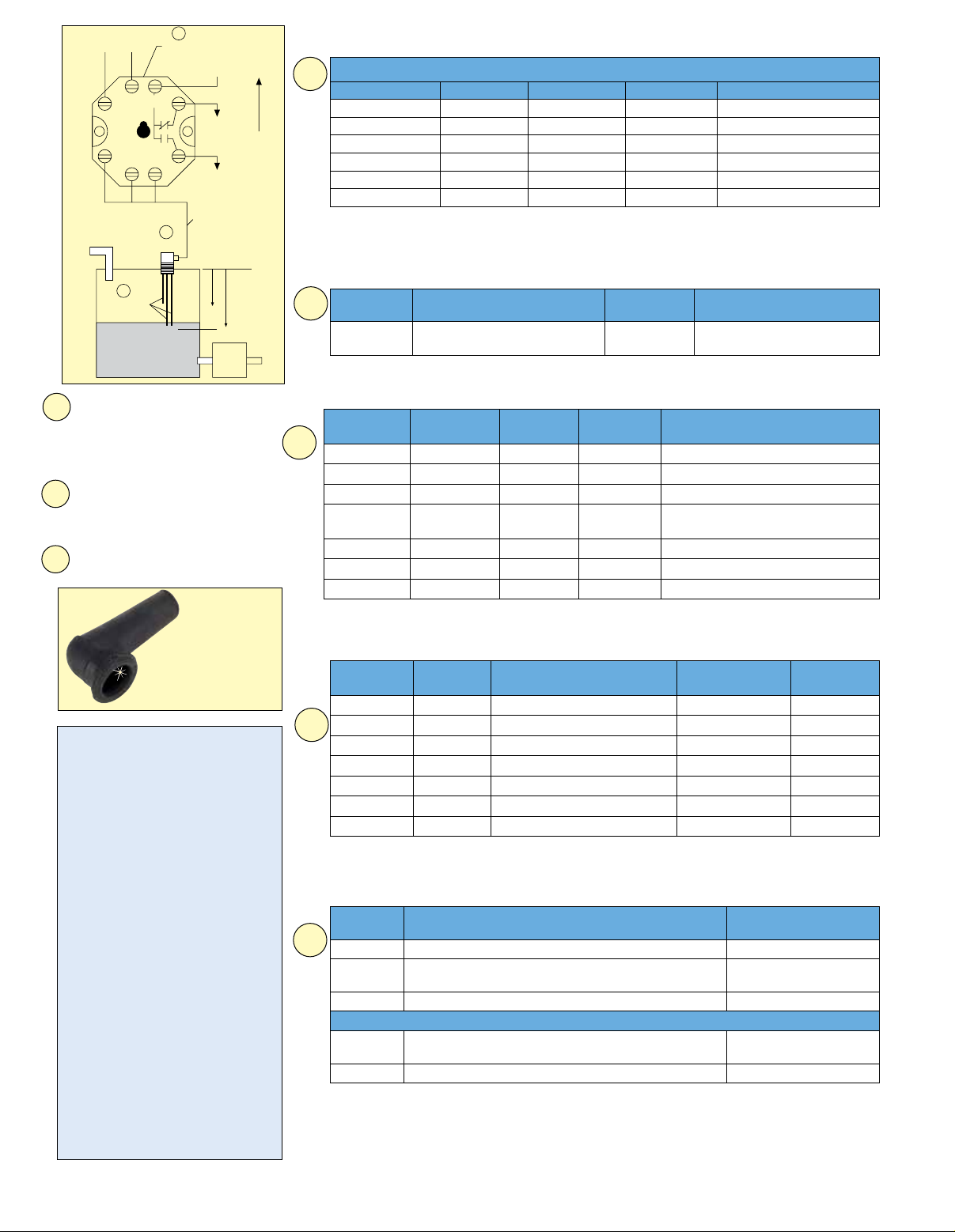
AC Supply
L2
H
Electrodes
3
Socket of
LVC 511
Neutral
Hot
L1
C
NC
To Load
(pump-up)
NO
GL
(pump-down)
3C
2
Fitting
1
To Load
Top
(Load)
Pump
From
Load
Electrode
Lengths
Electrodes
To Order
1
Model No. Material Model No. Material Length mm (inch)
LVC-E11
LVC-E12
LVC-E13
LVC-E14
LVC-E15
LVC-E16
* Beyond 1.8 m (72"), probes require PTFE sleeving at the tip to prevent swaying probes from
coming into contact with each other. For very long probes or in highly agitated tanks, spacers
may also be required. Consult OMEGA® Flow Department for further details.
303 SS
303 SS
303 SS
303 SS
303 SS
303 SS
LVC-E51
LVC-E52
LVC-E53
LVC-E54
LVC-E55
LVC-E56
316 SS 305 (12)
316 SS 610 (24)
316 SS 915 (36)
316 SS 1220 (48)
316 SS 1525 (60)
316 SS 1830 (72)*
Threaded Single Electrode Holders
2
Model No. Description
LVC-S3
3
⁄8 MNPT for 1 LVC-E
electrode open terminal
Wetted
Materials
316 SS/
PTFE
Maximum Pressure
at Maximum Temperature
400 psig at
231°C (448°F)
Select electrode length as
1
measured from the top of the
tank to the required activation
point. Determine the number of
electrodes necessary for your
application.
Select mounting style to match
tank. Select fitting that matches
2
the number of electrodes
selected. Select material to
match liquid.
Select the proper
3
electronic module.
LVR rubber boot
for electrode.
Ordering Example
It is desired to have a pump up control
system in a plastic tank holding
ordinary water. The components
ordered are:
1) 1 LVC-E11 electrode
2) 2 LVC-E12 electrodes
3) 1 LVC511 electronics module
4) 1 LVC-N3-BR 2 MNPT brass,
3-electrode mounting assembly
5) One 100' roll of TX4-100
4-conductor shielded copper cable
The LVC-E electrodes are all
threaded into the LVC-N3-BR. Low
level is at 24" below the top (between
the 2 LVC-E12 electrodes); high level
is at 12" below the top (between the
LVC-E12 and LVC-E11 electrodes).
The LVC511A can be wired for pumpup control, as well as for pump-down,
high-level, or low-level alarm. Three
of the 4 conductors of the TX4-100
cable are connected to the 3 probe
terminals inside the LVC-N3-BR
mounting assembly.
Threaded Multi-Electrode Assemblies (Includes Junction Box)
Stainless
Steel Brass
2
LVC-N1-SS LVC-N1-BR LVC-N1-C
LVC-N2-SS LVC-N2-BR LVC-N2-C
LVC-N3-SS LVC-N3-BR LVC-N3-C
LVC-N4-SS LVC-N4-BR LVC-N4-C
LVC-N5-SS LVC-N5-BR LVC-N5-C
LVC-N6-SS LVC-N6-BR LVC-N6-C
LVC-N7-SS LVC-N7-BR LVC-N7-C
All threaded assemblies rated for 250 psig, 208°C (406°F).
Cast
Iron
Wt.
kg (lb) Description
1.8 (3.9) 1 MNPT, for 1 LVC-E electrode
2.6 (5.7) 2 MNPT, for 2 LVC-E electrodes
3.25 (7.2) 2 MNPT, for 3 LVC-E electrodes
1
3.8 (8.4) 2
⁄2 MNPT, for 4 LVC-E
electrodes
5.2 (11.4) 3 MNPT, for 5 LVC-E electrodes
5.2 (11.4) 3 MNPT, for 6 LVC-E electrodes
5.25 (11.6) 3 MNPT, for 7 LVC-E electrodes
Flanged Multi-Electrode Assemblies (Includes Junction Box)
Stainless
Steel Cast Iron
LVC-F1-SS LVC-F1-CI
LVC-F2-SS LVC-F2-CI
2
LVC-F3-SS LVC-F3-CI
LVC-F4-SS LVC-F4-CI
LVC-F5-SS LVC-F5-CI
LVC-F6-SS LVC-F6-CI
LVC-F7-SS LVC-F7-CI
Standard flange is 125# cast iron rated for 125 psig, 178°C (353°F);
150# 316 SS flange rated for 225 psig.
Nominal Pipe, Flange Size
and Description
Flange Diagram
mm (inch)
1", for 1 LVC-E electrode 108 (4.25) 1.25 (2.75)
2", for 2 LVC-E electrodes 152 (6) 2.9 (6.5)
2", for 3 LVC-E electrodes 152 (6) 3.0 (6.7)
1
⁄2", for 4 LVC-E electrodes 178 (7) 3.6 (7.9)
2
3", for 5 LVC-E electrodes 190 (7.5) 5 (11)
3", for 6 LVC-E electrodes 190 (7.5) 4.9 (10.9)
3", for 7 LVC-E electrodes 190 (7.5) 4.9 (10.9)
Standard Relay Electronics
Model
Number
3
LVC511
LVC512
LVC521
Intrinsically Safe Relay Electronics
LVC551
LVC552
Comes complete with operator’s manual.
Direct action standard; for inverse action, add suffix “-INV” to model number; LVC551 and
LVC552, no additional cost.
Inverse normally used for pump-up or low-level applications.
For 240 Vac operation, add suffix “-240VAC” to model number, for additional cost for the
LVC552 and LVC512. For 24 Vdc operation, add suffix “-24V” to model number, for additional cost.
Description Maximum Media
Resistance
10 A resistive at up to 120 Vac, 8-pin socket 50,000
10 A resistive at up to 120 Vac, 11-pin socket (Field adjustable from
4700 to 1 million Ω)
10 A resistive at up to 120 Vac, open circuit board 50,000
8 A resistive at up to 120 Vac, FM listed (Field adjustable
from 0 to 470,000 Ω)
8 A resistive at up to 120 Vac, UL listed 100,000
Weight
kg (lb)
3
 Loading...