

Page 1
TM
NORWALK, CT
User’s Guide
Shop online at
omega.com
e-mail: [email protected]
For latest product manuals:
www.omegamanual.info
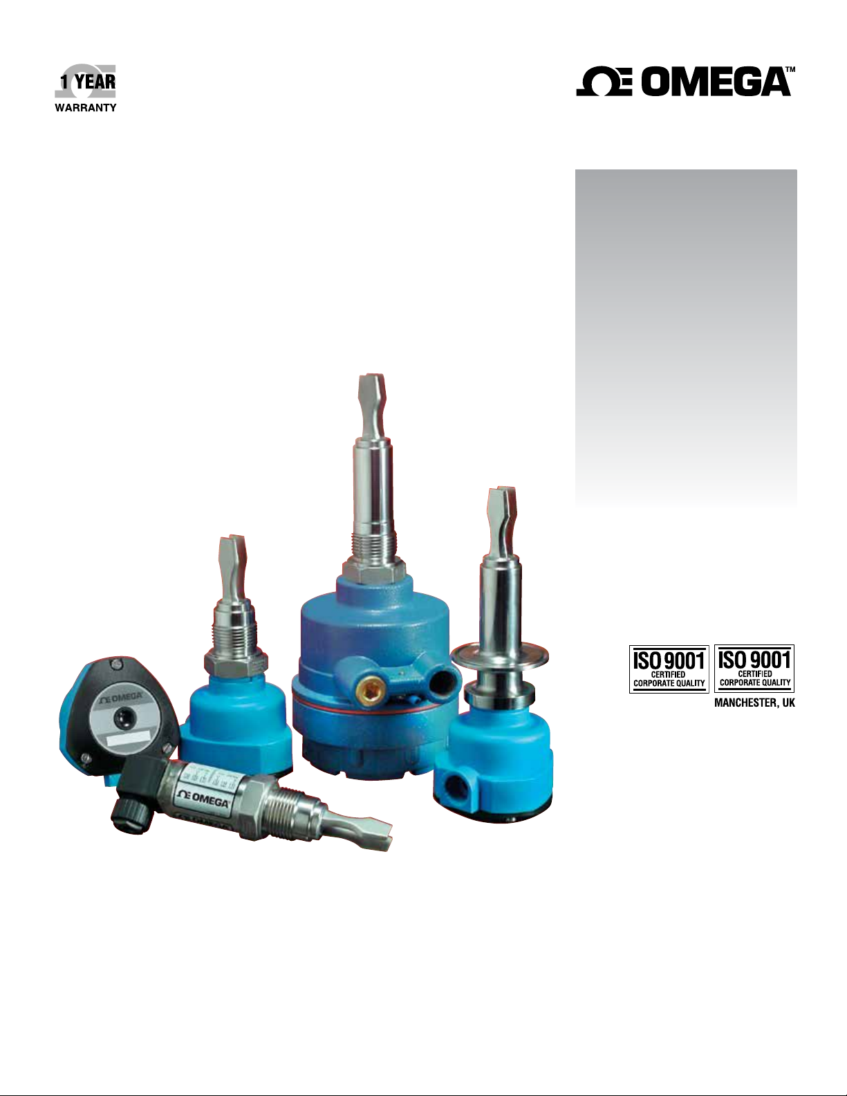
LTU2000 SERIES
Tuning Fork Point Level Switches
Page 2

omega.com [email protected]
Servicing North America:
U.S.A. Omega Engineering, Inc.
Headquarters: Toll-Free: 1-800-826-6342 (USA & Canada only)
Customer Service: 1-800-622-2378 (USA & Canada only)
Engineering Service: 1-800-872-9436 (USA & Canada only)
Tel: (203) 359-1660 Fax: (203) 359-7700
e-mail: [email protected]
For Other Locations Visit omega.com/worldwide
The information contained in this document is believed to be correct, but OMEGA accepts no liability for any errors it contains, and reserves
the right to alter specifications without notice.
Page 3

TM
Contents
Introduction . . . . . . . . . . . . . . . . . . . . . . . . . . . . . . . . . . . . . . . . . . . . . . . . . 5
Models. . . . . . . . . . . . . . . . . . . . . . . . . . . . . . . . . . . . . . . . . . . . . . . . . . . . . 6
Models and Dimensions . . . . . . . . . . . . . . . . . . . . . . . . . . . . . . . . . . . . . . . 7
Wiring Diagram . . . . . . . . . . . . . . . . . . . . . . . . . . . . . . . . . . . . . . . . . . . . . . 8
LTUP and LTUR Status Guide. . . . . . . . . . . . . . . . . . . . . . . . . . . . . . . . . . 11
LTUM Status Guide . . . . . . . . . . . . . . . . . . . . . . . . . . . . . . . . . . . . . . . . . . 12
Installation . . . . . . . . . . . . . . . . . . . . . . . . . . . . . . . . . . . . . . . . . . . . . . . . . 13
Handling . . . . . . . . . . . . . . . . . . . . . . . . . . . . . . . . . . . . . . . . . . . . . . . . . . 14
Technical Specifications . . . . . . . . . . . . . . . . . . . . . . . . . . . . . . . . . . . . . . 15
Trouble Shooting . . . . . . . . . . . . . . . . . . . . . . . . . . . . . . . . . . . . . . . . . . . 19
Notes . . . . . . . . . . . . . . . . . . . . . . . . . . . . . . . . . . . . . . . . . . . . . . . . . . . . 20
03
Page 4

Introduction
LTU-2000 Series:
Point Level Switch
Omega's LTU-2000 Series use a piezo-electric crystal that enables the switch to vibrate
at a fixed pre-defined resonant frequency. When the tuning fork is submerged in the
medium the frequency at which the switch is vibrating, changes. This change is detected
unit’s
by the electronics and is converted into a switch output (either relay or PNP/NPN
depending on the model).
The red LED in the housing stays blinking when the is in contact with the
product. The same light stays on continuously when there is no contact with the product,
giving a positive indication at all times that the LTU-2000 is working.
All models are made with 316 Stainless Steel and are available with ECTFE or epoxy
coatings and hygienic fittings for sanitary applications. Standard versions can operate at
temperatures up to 80ºC (176ºF) and higher temperature versions can operate at
temperatures up to 120ºC (248ºF). All models (except the mini-versions) have adjustable
time delay adjustment of 1, 5, 10 or 20 seconds and also have a Wet/Dry selection for
both High and Low level application requirements.
LTU-2000
Features
Unaffected by variations in density, conductivity, dielectric constant or viscosity
Unaffected by foam, tank agitation or vibration
Available in Threaded, Sanitary and Flanged connections
Available with customized length options to best suit your application
All 316SS body and wetted parts, coating when necessary
Adjustable response time (from 1 to 20 seconds)
Relay and Transistor outputs available
ECTFE
04
Page 5
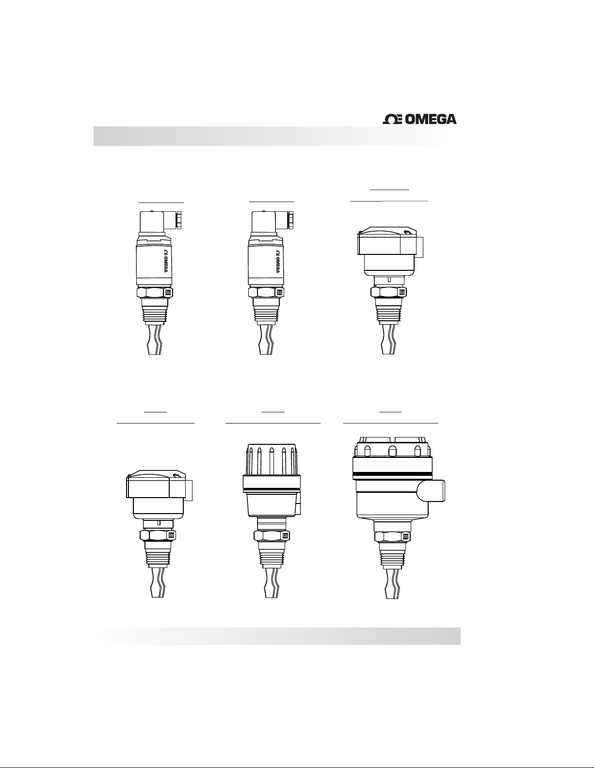
Models
LTUM1-DC
LTUM2-AC
TM
LTUP-DC
HOUSINGNYLON
LTUM1-DC
®
LTUR
NYLON HOUSING
LTUM2-AC
®
LTUR
ALUMINUM HOUSING
LTUR
ALUMINUM HOUSING
05
Page 6
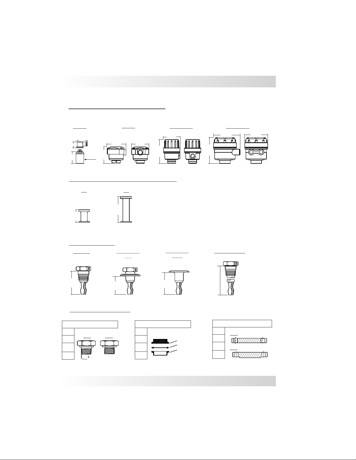
Models and Dimensions
Mounting Options for LTU-2000
LTUM
48mm
28mm
56mm
ø38mm
Nylon
89mm
76mm
80mm
Aluminum Aluminum
89mm
126mm
Extended Necks for High Temperature
MT
50mm
Extended necks for medium (up to 100ºC) and high temperature (up to 120ºC)temperature
HT
100mm
Insertion Length
Standard
80mm
TC Standard
LTU
64mm
TC Standard
80mm
LTUM
130mm
130mm
Extended Length
L
118mm
Process Connections
Threaded Connections
3/4”
1”
1 ½”
2”
NPT
1,75
BSP
Tri-Clamp Connection
1 ½”
2”
2 ½”
3”
TC Connection
Rubber Seal
Process Connection
Flange Connections
1”
FF
1 ½”
2”
RF
2 ½”
ANSI 150#
ANSI 300#
06
Page 7
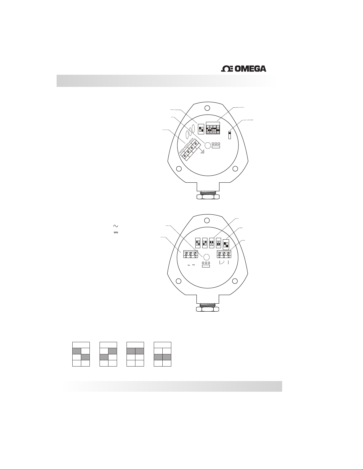
Wiring Diagram
TM
LTUP - Housing
- Power Supply (+)
1
2 - Power Supply (-)
3 - PNP/NPN Output
or +24v/0v (Max 500mA)
4 -
Ground
Time Delay
Central LED
Power Supply
LTUP - with M12 Connector
1
- Power Supply (+)
2 - Power Supply (-)
3 - PNP/NPN Output
or +24v/0v (Max 500mA)
4 -
Ground
LTUR - Universal Power Supply
Nylon Housing
- Power Supply (L)
1
2 - Power Supply (-)
3 - Power Supply (+)
AC ( )
}
}
DC ( )
Power Supply
4 - NC Contact
5 - Common
6- NO Contact
LTUR - with M12 Connector
- Power Supply (L) or (+)
1
2 - Power Supply (-)
3 - NO Contact
4 - NC Contact
5 - Common
Time Delay Guide
ON
1
5
ON
10
ON
Central LED
20
ON
Time Delay Guide
Wet/Dry
3
OUT
2
_
1
+
20 … 60 V dc
( IL ) 500 mA Máx
5
10
20
1
ON
ON
ON
ON
ON
1
1
1
1
2
2
2
2
WET
DRY
WET
DRY
Mode
2
1
4
Time Delay Guide
Time Delay
5
10
1
3
1
2
-
L
1&2 (85... 264Vac (50/60Hz))
2&3 (18...36Vdc)
WET
+
DRY
20
ON
1
4
5
C
NC
Relay Contact
5A - 220Vac
2
6
NO
Power Supply
AC: 85... 264Vac (50/60Hz)
< 10mA
(I)
DC: 18...36Vdc
< 6mA
(I)
The different key positions indicate the time
delay in seconds.
1
2
1
2
1
2
1
2
( 1 ; 5 ; 10 ; 20 sec. )
07
Page 8
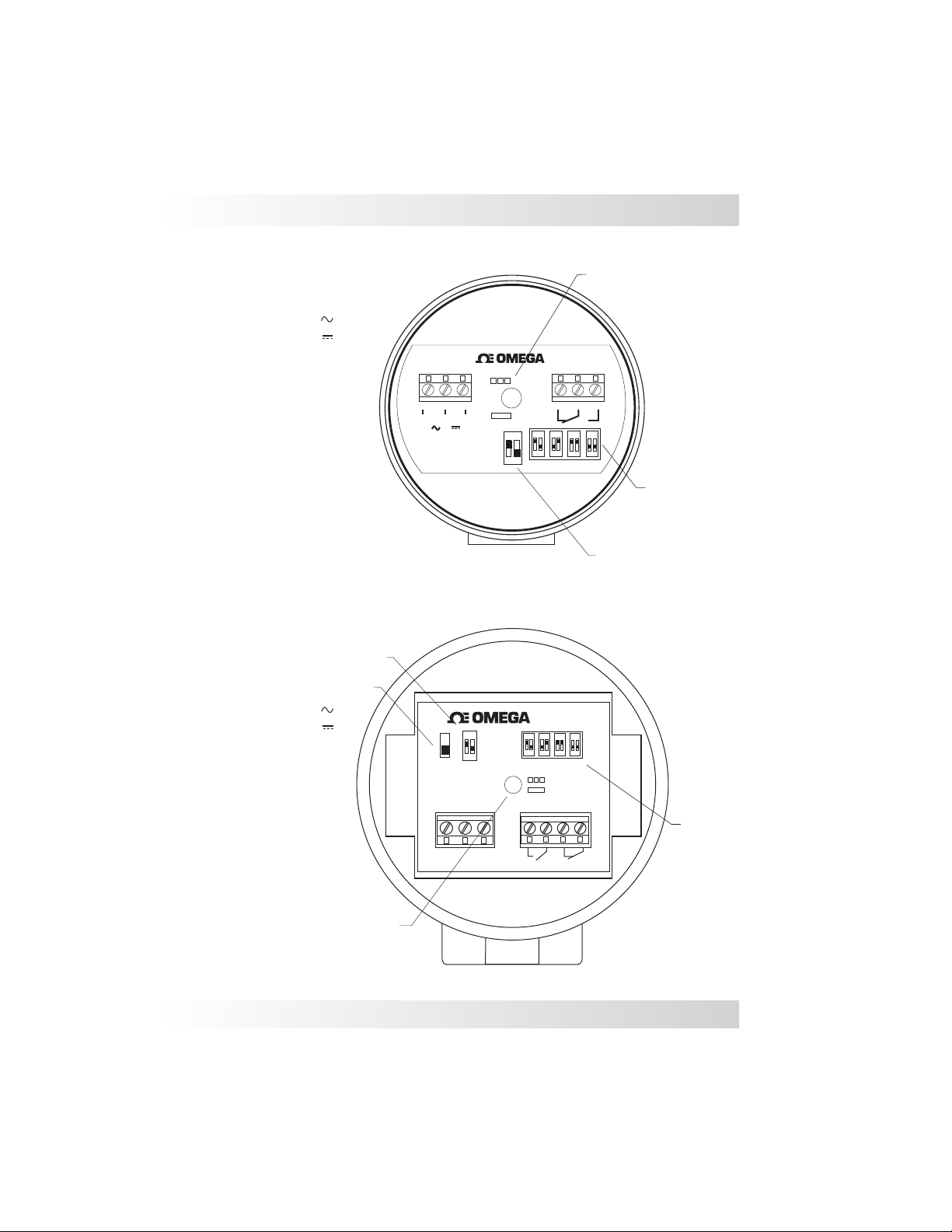
Wiring Diagram
LTUR - Universal Power Supply
Small Aluminum Housing
- Power Supply (L)
1
2 - Power Supply (-)
3 - Power Supply (+)
AC ( )
}
}
DC ( )
4 - NC Contact
5 - Common
6 - NO Contact
LTUR - with
M12 connector
- Power Supply (L) or (+)
1
2 - Power Supply (-)
3 - NO Contact
4 - NC Contact
5 - Common
1 & 2 (85...260 Vac)
2 & 3 (18...36 Vdc)
LTUR - Universal Power Supply
Large Aluminum Housing
Time Delay
Output Logic Inversion
- Power Supply (L)
1
2 - Power Supply (-)
3 - Power Supply (+)
4 - NO Contact
5 - NO Common
6 - NC Contact
7 - NC Common
AC ( )
}
}
DC ( )
1 2
L
A
B
3
-
+
LTUR
ON
1
S1
Supply:
AC: 85...260V
DC: 18...24V
1 2
Central LED
TM
5 6
4
Wet
Dry
S
E
C
20
10
Time Delay
Guide
1 2
ON
5
1
Time Delay
TM
4
1
LTUR
5
Wet
Dry
5 6
S
E
C
20
10
7
Time Delay
Guide
D
E
L
A
2
Y
3
Central LED
L
-
+
AC
DC
N O
N C
08
Page 9
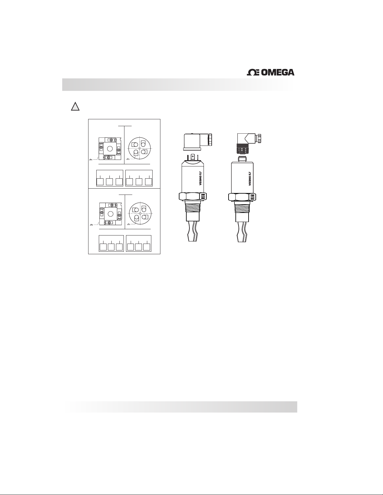
Wiring Diagram
To avoid burning the unit, make sure that the load has been
!
installed in series with the LTUM before powering it up.
LTUM1
1
LTUM2
3
1
N
1
Out
3
L1
M12
2
3
5
1
4
NO
0V
+V
1
2
M12
2
3
5
1
4
NC
N
1
3
2
DIN 43650
2
4
NC
Out
+V
3
2
DIN 43650
2
4
3
3
1
0V
NO
L1
2
LTUM
TM
LTUM
®
®
09
Page 10
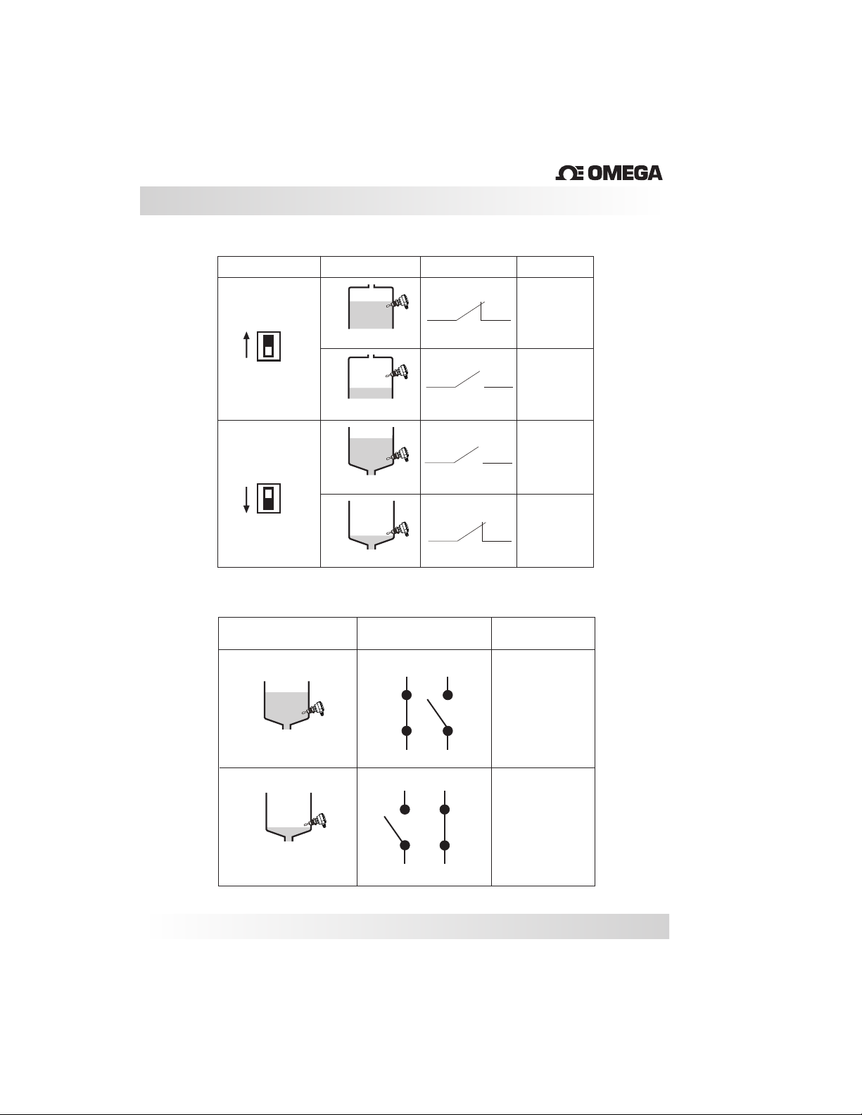
LTUP and LTUR Status Guide
For LTUP / DC
TM
Switch Position
Level
WET
Probe Covered
Maximum
fail-safe
Probe Uncovered
DRY
Probe Covered
Minimum
fail-safe
Probe Uncovered
For LTUR (Universal Power Supply)
Level
NO - NC
4
5
Out
Central LED
WET
(Blink)
DRY
(On)
WET
(Blink)
DRY
(On)
Central LED
Probe Covered
Probe Uncovered
WET
(Blink)
5
6
5
4
DRY
(On)
5
6
10
Page 11
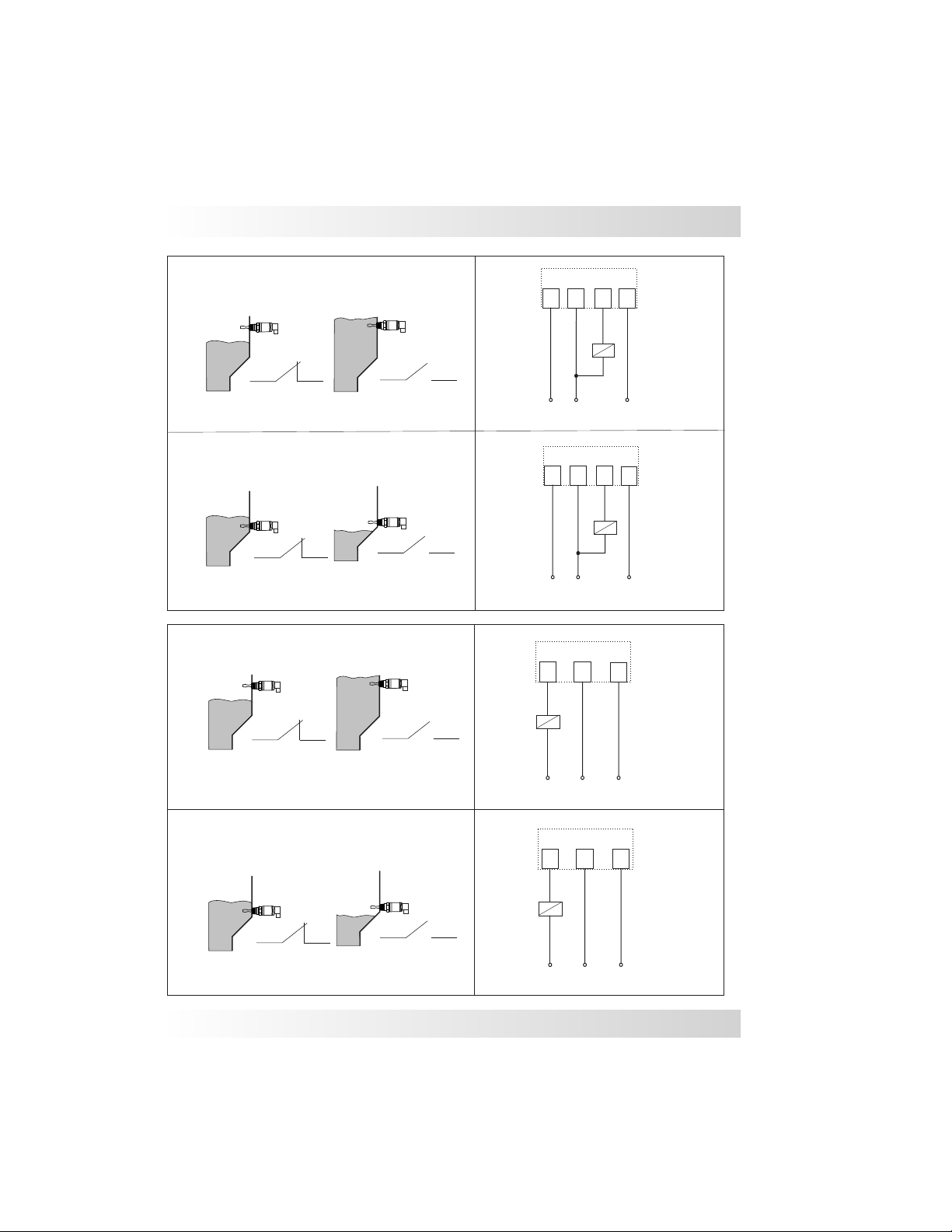
LTUM Status Guide
LTUM1 / DC ( Operating Mode NC )
LTUM1 / DC ( Operating Mode NO )
LTUM2 / AC ( Operating Mode NC )
Connector Pins
3
(+)
2
(+)
Connector Pins
3
external
load
2
1
external
load
(-)
Connector Pins
1
external
load
(-)
1
3
4
(GND)
4
(GND)
4
LTUM2 / AC ( Operating Mode NO )
N
L1
Connector Pins
2
1
external
load
N
L1
(GND)
4
(GND)
11
Page 12
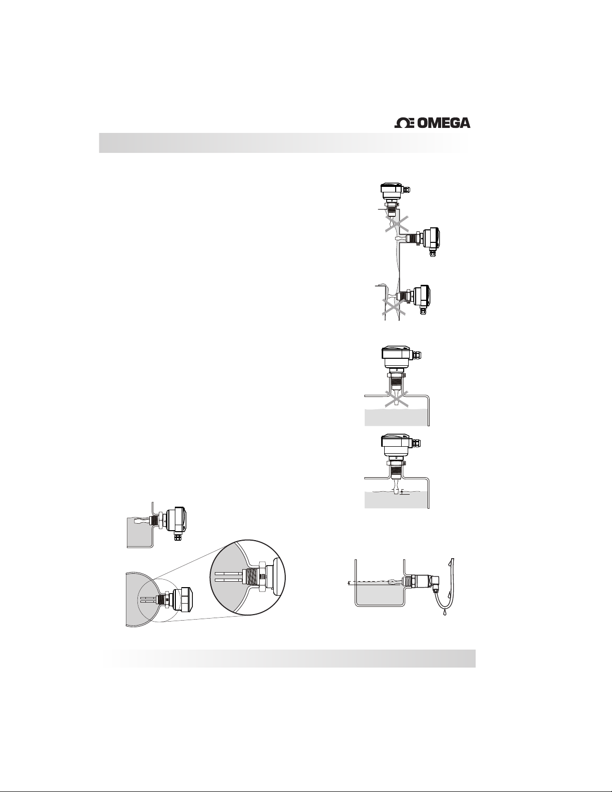
Installation
TM
Confirm that the wire connections are correct
and that the available power supply is
compatible with the LTU unit.
Verify that the operating pressure and
temperature of the process corresponds to the
operating parameters of the unit.LTU
The can be installed at any angle of the pipe or
LTU
vessel to detect the presence of liquids.
Verify that the forks are inserted into the medium
until the proper point within the vessel and that
they stay clear from the inside walls (Fig. 1 and 2).
Ensure that the conduit is facing downward and
makes a U-turn on the bottom of the cable to avoid
moisture from entering the housing enclosure
(Fig.3).
For proper installation of the use the mark as a
LTU
reference for correctly positioning the forks. It is
recommended that the correct orientation be used
to avoid build up between the forks (Fig. 4).
Side View
(Fig.4)
(Fig.1)
(Fig.2)
Switching
hysteresis
1mm
Switching
point=1/2” (13mm)
Top View
(Fig.3)
Switching
hysteresis
1mm
Switching
point=1/2” (12mm)
12
Page 13

Seal the thread with Teflon tape before
installation (Fig. 1).
Handling
Fig. 1
Do not thread the unit into the vessel, or turn it,
by the housing (Fig. 2).
Use the correct tools during the installation of
the (Fig. 3). LTU
The should not be dropped or suffer any
LTU
impact or fall that could damage the electronics,
coating or the forks of the probe (Fig. 4 and 5).
Periodic visual inspection of the is required to
check for corrosion or deposit build-up. If deposits
are found, clean the sensor to ensure optimum
performance.
When cleaning the Forks use a soft brush to
ensure that the coating or polishing is not
damaged or scratched.
Do not alter or bend the shape of the forks ( Fig. 6).
LTU
Fig. 2
Fig. 3
Fig. 4
Fig. 5
Fig. 6
13
Page 14
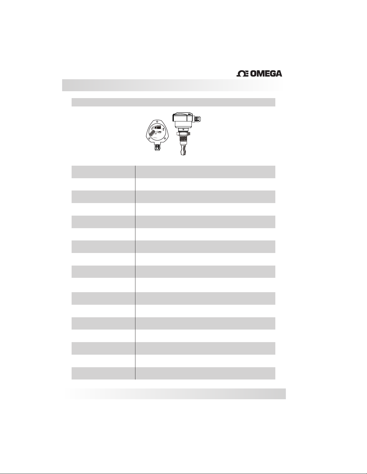
Technical Specifications
LTUP
151020
ON
ON
ON
ON
ON
1
1
1
1
2
2
2
2
WET
2
1
DRY
Mode
WET
4
DRY
3
OUT
_
1 2
+
18 … 60 V dc
( IL ) 500 mA Máx
Nylon Enclosure
TM
Application
Operating Voltage
Current Consumption
Output
Medium V iscosity
Accuracy
Repeatability
Time Delay
Switching Point
Load Current
Enclosure Material
Electrical Connection
Process Connection
Wetted Material
Level Switch for Liquids
20...60 Vdc
+/- 3mA
PNP (3 wires)
Max.: 20.000cs
0.1%
< 0.5mm
1 to 20 seconds (adjustable)
13mm from tip
500mA
Glass Filled Nylon
½” NPT, M12 Connector or Cable Gland
3/4” to 1 ½” BSP, NPT or Sanitary
316 Stainless Steel
Operating Temperature
Max Pressure
Class Protection
-14 to 176º F (-10 to 80ºC)
725 PSI (50 Bar)
IP 65
14
Page 15
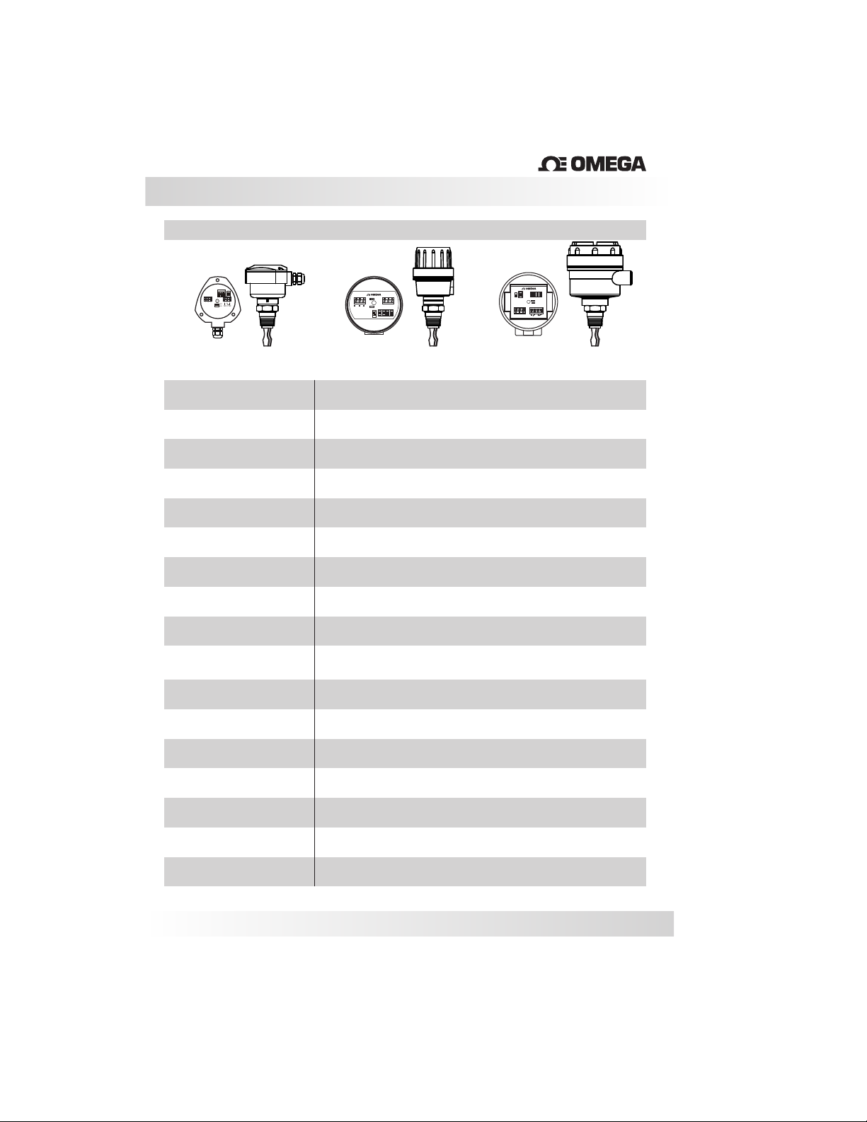
Technical Specifications
LTUR
TM
151020
ON
ON
ON
ON
ON
1
1
1
1
2
2
2
2
2
1
4
5
6
3
1
2
WET
DRY
NOC NC
Nylon Enclosure
Application
Operating Voltage
Current Consumption
Output
Medium V iscosity
Accuracy
Repeatability
Time Delay
Switching Point
Load Current Relay
Enclosure Material
®
5 6
1 234
Wet
Dry
-
+
L
S
ON
E
1 & 2 (85...260 Vac)
C
2 & 3 (18...36 Vdc)
1 2
5
20
10
1
VTK-G1
Level Switch for Liquids
18...36 Vdc
85...264 Vac (50/60Hz)
DC < 6mA
AC < 10mA
Relay (SPDT) N1, G1 / (1NO+1NC) G2
Max.: 20.000cs
0.1%
< 0.5mm
1 to 20 seconds (adjustable)
13mm from tip
5A ( 250 Vac)
Glass Filled Nylon or Aluminum
®
D
ON
S
A
E
E
L
C
A
B
1
2
Y
S1
5
20
10
1
Supply:
Wet
AC: 85...260V
Dry
DC: 18...24V
3
5 6
1 2
4
7
L
-
+
N O
N C
AC
DC
Aluminum EnclosureAluminum Enclosure
Electrical Connection
Process Connection
Wetted Material
Operating Temperature
Max Pressure
Class Protection
½” NPT, M12 Connector or Cable Gland
3/4” to 1 ½” BSP, NPT or Sanitary
316 Stainless Steel
-14 to 176º F (-10 to 80ºC)
725 PSI (50 Bar)
IP 65
15
Page 16
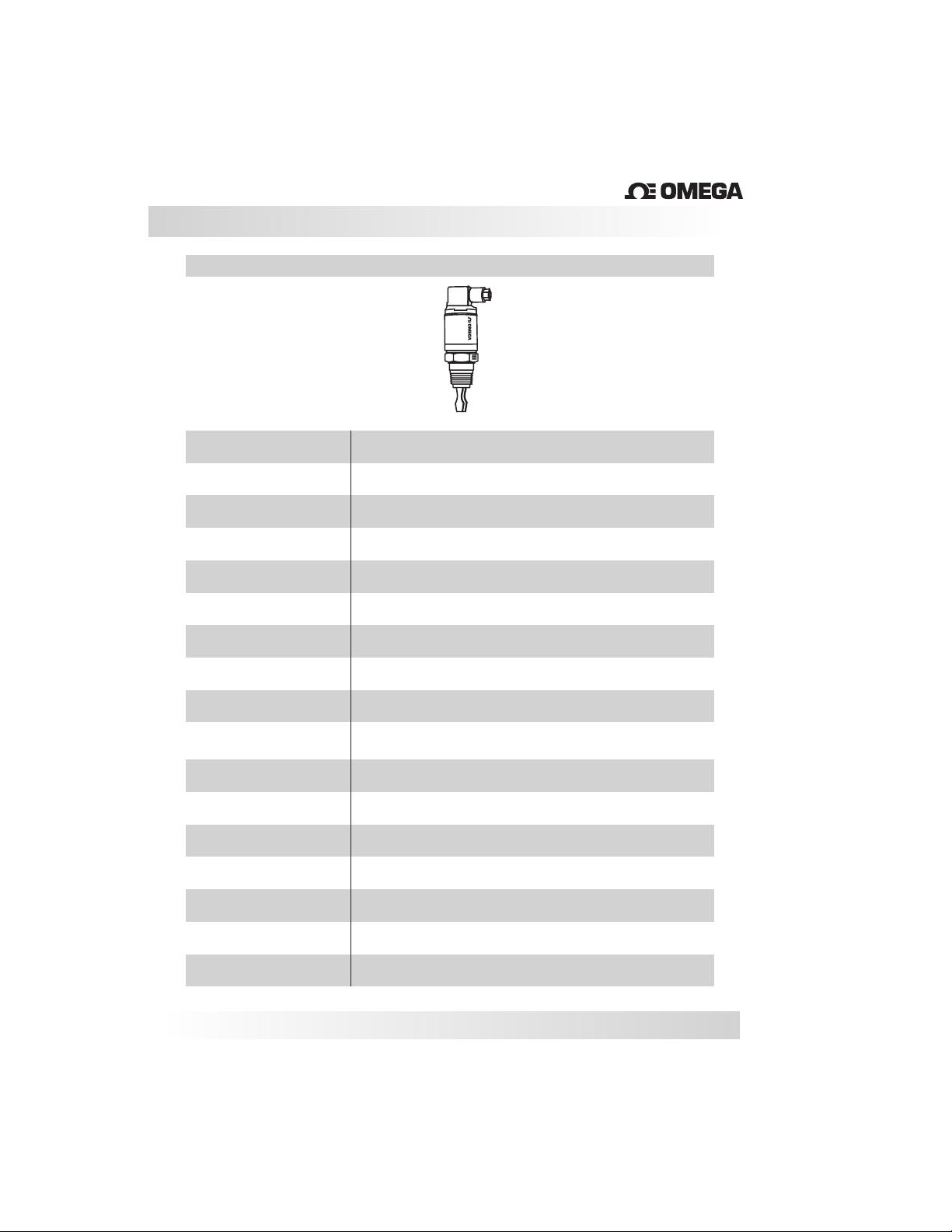
Technical Specifications
LTUM1
LTUM1
TM
LTUM1-DC
®
Application
Operating Voltage
Current Consumption
Output
Medium V iscosity
Accuracy
Repeatability
Time Delay
Switching Point
Load Current
Enclosure Material
Electrical Connection
Process Connection
Wetted Material
Level Switch forLliquids
20...60 Vdc
+/- 3mA
PNP (3 Wires)
Max.: 20.000cs
0.1%
< 0.5mm
1 sec.
13mm from tip
500mA
316 Stainless Steel
Plug DIN 43650 / M12 Connector
3/4” to 1 ½” BSP, NPT or Sanitary
316 Stainless Steel
Operating Temperature
Max Pressure
Class Protection
-14 to 248º F (-10 to 120ºC)
725 PSI (50 Bar)
IP 65 DIN 43650 connector
IP 67 M12 connector
16
Page 17

LTUM2
Technical Specifications
LTUM2
LTUM2-AC
®
Application
Operating Voltage
Current Consumption
Output
Medium V iscosity
Accuracy
Repeatability
Time Delay
Switching Point
Load Current
Enclosure Material
Electrical Connection
Process Connection
Wetted Material
Level Switch for Liquids
85...264 Vac
+/- 3mA
Direct Load Switching (2 Wire)
Max.: 20.000cs
0.1%
< 0.5mm
1 sec.
13mm from tip
100mA
316 Stainless Steel
Plug DIN 43650 / M12 Connector
3/4” to 1 ½” BSP, NPT or Sanitary
316 Stainless Steel
Operating Temperature
Max Pressure
Class Protection
-14 to 248º F (-10 to 120ºC)
725 PSI (50 Bar)
IP 65 DIN 43650 connector
IP 67 M12 connector
17
Page 18

Trouble Shooting
TM
Fault
Does not switch
Incorrect
switching
Case
The central LED is not on
The LED flashes 3 times/sec.
The LED flashes once
every 2 seconds
The LED flashes once
every 4 seconds
The Fork is encrusted with
build-up
Dry = on
Wet = on
Fast switching
Verify the Power Supply
High current load or short circuit.
Properly configure the key switch
Select a longer time delay
Solution
Internal failure
Internal failure
Check the installation.
Clean the forks
18
Page 19

WARRANTY/DISCLAIMER
OMEGA ENGINEERING, INC. warrants this unit to be free of defects in materials and workmanship for a
period of 13 months from date of purchase. OMEGA’s WARRANTY adds an additional one (1) month
grace period to the normal one (1) year product warranty to cover handling and shipping time. This
ensures that OMEGA’s customers receive maximum coverage on each product.
If the unit malfunctions, it must be returned to the factory for evaluation. OMEGA’s Customer Service
Department will issue an Authorized Return (AR) number immediately upon phone or written request.
Upon examination by OMEGA, if the unit is found to be defective, it will be repaired or replaced at no
charge. OMEGA’s WARRANTY does not apply to defects resulting from any action of the purchaser,
including but not limited to mishandling, improper interfacing, operation outside of design limits,
improper repair, or unauthorized modification. This WARRANTY is VOID if the unit shows evidence of
having been tampered with or shows evidence of having been damaged as a result of excessive corrosion;
or current, heat, moisture or vibration; improper specification; misapplication; misuse or other operating
conditions outside of OMEGA’s control. Components in which wear is not warranted, include but are not
limited to contact points, fuses, and triacs.
OMEGA is pleased to offer suggestions on the use of its various products. However,
OMEGA neither assumes responsibility for any omissions or errors nor assumes liability for
any damages that result from the use of its products in accordance with information provided
by OMEGA, either verbal or written. OMEGA warrants only that the parts manufactured by the
company will be as specified and free of defects. OMEGA MAKES NO OTHER WARRANTIES OR
REPRESENTATIONS OF ANY KIND WHATSOEVER, EXPRESSED OR IMPLIED, EXCEPT THAT OF
TITLE, AND ALL IMPLIED WARRANTIES INCLUDING ANY WARRANTY OF MERCHANTABILITY
AND FITNESS FOR A PARTICULAR PURPOSE ARE HEREBY DISCLAIMED. LIMITATION OF
LIABILITY: The remedies of purchaser set forth herein are exclusive, and the total liability of
OMEGA with respect to this order, whether based on contract, warranty, negligence,
indemnification, strict liability or otherwise, shall not exceed the purchase price of the
component upon which liability is based. In no event shall OMEGA be liable for
consequential, incidental or special damages.
CONDITIONS: Equipment sold by OMEGA is not intended to be used, nor shall it be used: (1) as a “Basic
Component” under 10 CFR 21 (NRC), used in or with any nuclear installation or activity; or (2) in medical
applications or used on humans. Should any Product(s) be used in or with any nuclear installation or
activity, medical application, used on humans, or misused in any way, OMEGA assumes no responsibility
as set forth in our basic WARRANTY/DISCLAIMER language, and, additionally, purchaser will indemnify
OMEGA and hold OMEGA harmless from any liability or damage whatsoever arising out of the use of the
Product(s) in such a manner.
RETURN REQUESTS/INQUIRIES
Direct all warranty and repair requests/inquiries to the OMEGA Customer Service Department.
BEFORE RETURNING ANY PRODUCT(S) TO OMEGA, PURCHASER MUST OBTAIN AN AUTHORIZED
RETURN (AR) NUMBER FROM OMEGA’S CUSTOMER SERVICE DEPARTMENT (IN ORDER TO AVOID
PROCESSING DELAYS). The assigned AR number should then be marked on the outside of the return
package and on any correspondence.
The purchaser is responsible for shipping charges, freight, insurance and proper packaging to prevent
breakage in transit.
FOR WARRANTY RETURNS, please have the
following information available BEFORE contacting
OMEGA:
1. Purchase Order number under which the product
was PURCHASED,
2. Model and serial number of the product under
warranty, and
3. Repair instructions and/or specific problems
relative to the product.
OMEGA’s policy is to make running changes, not model changes, whenever an improvement is possible. This affords
our customers the latest in technology and engineering.
OMEGA is a trademark of OMEGA ENGINEERING, INC.
© Copyright 2018 OMEGA ENGINEERING, INC. All rights reserved. This document may not be copied, photocopied,
reproduced, translated, or reduced to any electronic medium or machine-readable form, in whole or in part, without the
prior written consent of OMEGA ENGINEERING, INC.
FOR NON-WARRANTY REPAIRS,
OMEGA for current repair charges. Have
the following information available BEFORE
contacting OMEGA:
1. Purchase Order number to cover the COST
of the repair,
2. Model and serial number of the product, and
3. Repair instructions and/or specific problems
relative to the product.
consult
Page 20

Where Do I Find Everything I Need for
Process Measurement and Control?
OMEGA…Of Course!
Shop online at omega.com
TEMPERATURE
MU
Thermocouple, RTD & Thermistor Probes, Connectors, Panels & Assemblies
MU
Wire: Thermocouple, RTD & Thermistor
MU
Calibrators & Ice Point References
MU
Recorders, Controllers & Process Monitors
MU
Infrared Pyrometers
PRESSURE, STRAIN AND FORCE
MU
Transducers & Strain Gages
MU
Load Cells & Pressure Gages
MU
Displacement Transducers
MU
Instrumentation & Accessories
FLOW/LEVEL
MU
Rotameters, Gas Mass Flowmeters & Flow Computers
MU
Air Velocity Indicators
MU
Turbine/Paddlewheel Systems
MU
Totalizers & Batch Controllers
pH/CONDUCTIVITY
MU
pH Electrodes, Testers & Accessories
MU
Benchtop/Laboratory Meters
MU
Controllers, Calibrators, Simulators & Pumps
MU
Industrial pH & Conductivity Equipment
DATA ACQUISITION
MU Communications-Based Acquisition Systems
MU Data Logging Systems
MU Wireless Sensors, Transmitters, & Receivers
MU Signal Conditioners
MU Data Acquisition Software
HEATERS
MU
Heating Cable
MU
Cartridge & Strip Heaters
MU
Immersion & Band Heaters
MU
Flexible Heaters
MU
Laboratory Heaters
ENVIRONMENTAL
MONITORING AND CONTROL
MU
Metering & Control Instrumentation
MU
Refractometers
MU
Pumps & Tubing
MU
Air, Soil & Water Monitors
MU
Industrial Water & Wastewater Treatment
MU
pH, Conductivity & Dissolved Oxygen Instruments
M3991/1218
 Loading...