

Page 1

1
Page 2

2
Page 3

INTRODUCTION StepOne
AboutPoweredLevelSwitches:Thismanualcontainsinformationontwoseriesofpoweredlevelswitches;
Ultrasonic(LVU‐150series),TuningFork(LTU‐101Aseries)OpticLeak(LVF‐210Aseries)andCapacitance(LVC‐
152 series).The switches all feature two outputs: 1) a 4 or 20mA current switch and2) a60VA SPSTdry
contact relay.All four series are manufactured with thermoplastics, including the cable, making them
submersible in design and ideal for corrosive applications.Package the switches with either Omega
Engineeringcontrollers(LVCN‐100seriesorLVCN‐120series)orinterfacedirectlytoanothercontrollerorPLC.
TableofContents
Specifications(Common):......................................................................................................................................4
UltrasonicSwitch(LVU‐150Series):...........................................................................................................5
TuningFork(LTU‐101ASeries):..................................................................................................................6
MaintenanceAlarm:......................................................................................................................7
OpticLeakDetection(LVF‐210Aseries):....................................................................................................8
CapacitanceSwitch(LVC‐152Series):......................................................................................................10
SafetyPrecautions:..............................................................................................................................................12
MakeaFail‐SafeSystem:..........................................................................................................................13
Installation:..........................................................................................................................................................14
ThroughWallInstallation:........................................................................................................................14
TopWallInstallation:...............................................................................................................................14
Electrical:..............................................................................................................................................................15
Wiring:..................................................................................................................................................................16
WiringtoaOmegaEngineeringController:.............................................................................................16
WiringtheRelayOutput:.........................................................................................................................17
WiringasaP‐ChannelorN‐ChannelOutput:..........................................................................................18
Maintenance:.......................................................................................................................................................19
Cleaningprocedure:.................................................................................................................................19
LTU‐101ASeriesMaintenanceAlarm:.....................................................................................................19
TestingtheInstallation:...........................................................................................................................20
3
Page 4
SPECIFICATIONS(common) StepTwo
CommonSpecifications:
Orientation: Universal
Accuracy:±1mminwater
Repeatability:±0.5mminwater
Supplyvoltage: 12‐36VDC
12‐30VDC(LTU‐101Aonly)
Consumption: 25mAmaximum
Contacttype: (1)SPSTrelay
Contactrating: 60VA
Contactoutput: SelectableNO/NC
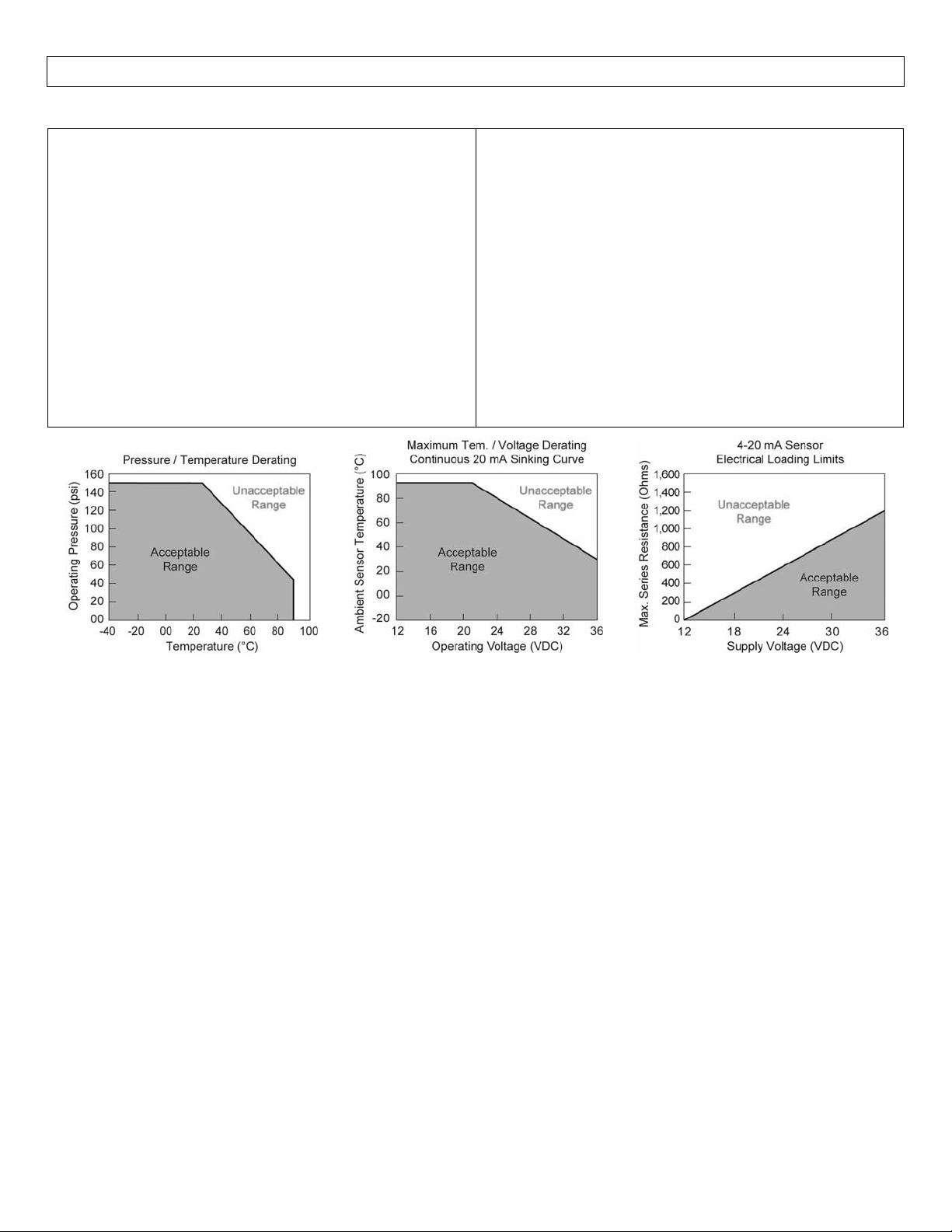
Processtemp.: F:‐40°to176°
C:‐40°to80°
Pressure: 150psi(10bar)@25°C.,derated
@1.667psi(.113bar)per°C.
above25°C.
Sensorrating: NEMA6(IP68)
Cabletype: 4‐conductor,#22AWG(shielded)
Cablelength: 10'(3m)‐Standard
25'(7.6m)or50'(15.2m)‐Special
Processmount: 3/4"NPT(3/4”G/R)
Classification: Generalpurpose
Mount.Gasket: FKM(Gversiononly)
CEcompliance: EN61326EMC/EN61010‐1safety
4
Page 5
SPECIFICATIONS(ultrasonic) StepTwo
UltrasonicSwitch(LVU‐150series):TheUltrasoniclevelswitchgeneratesa1.5MHzultrasonicwavefroma
miniaturepiezoelectrictransducerlocatedononesideofthegapinitssensingtip.Anotherpiezotransducer
locatedontheothersideofthegapactsasamicrophone,pickingupthesound.Whenliquidentersthegapin
thesensingtip,theaudiolevelchanges.
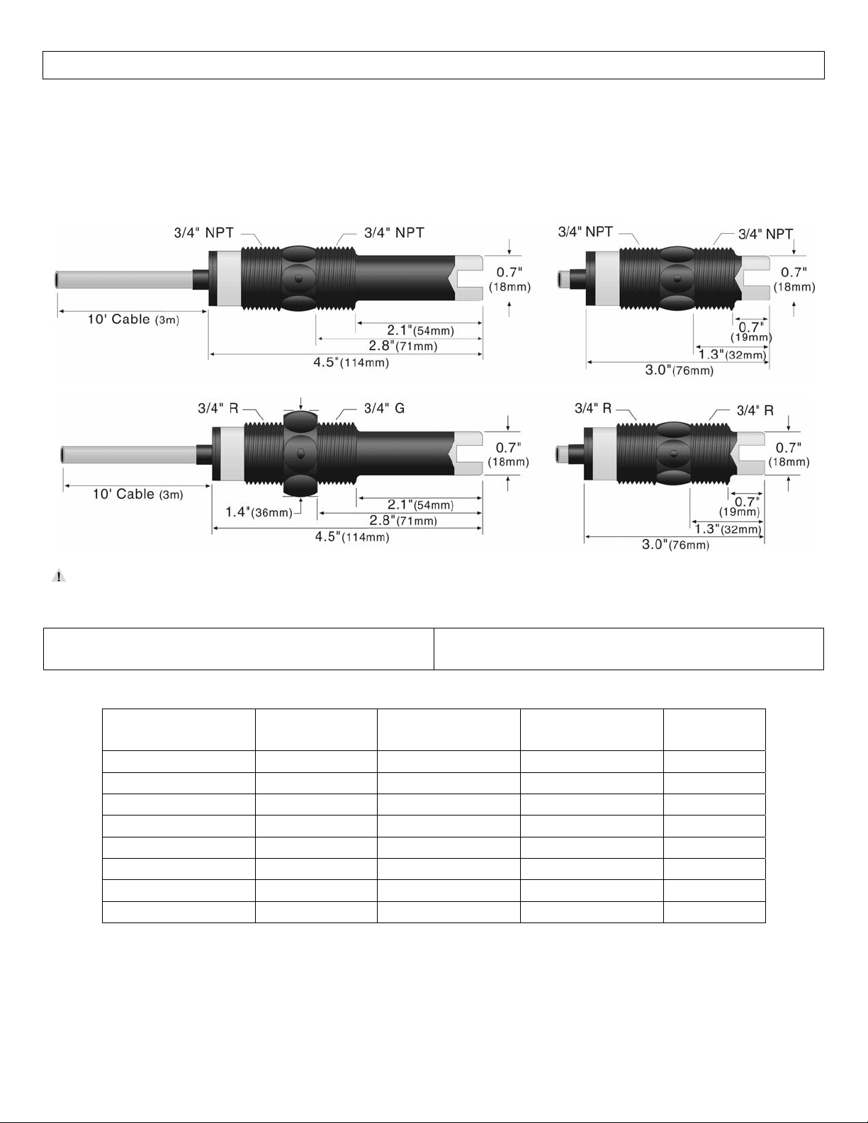
LVU‐152‐R&LVU‐153‐R LVU‐150‐R&LVU‐151‐R
LVU‐152‐G‐R&LVU‐153‐G‐R LVU‐150‐G‐R&LVU‐151‐G‐R
Thesensorshouldbeinstalledsothattheliquidwilldripoutofthegapwhenthesensorbecomesdry.
LVU‐150SeriesSpecifications:
Sensormaterial:‐150/‐152:PP
‐151/‐153:PFA
Cablejacketmat’l:‐150/‐152:PP
‐151/‐153:PFA
Configurations:
Part
Number
Length
Material
(body)
Material
(cable)
Cable
Length
LVU‐150‐R Short(3”) Polypropylene Polypropylene 10’
LVU‐150‐G‐R Short(3”) Polypropylene Polypropylene 10’
LVU‐151‐R Short(3”) PFA FEP 10’
LVU‐151‐G‐R Short(3”) PFA FEP 10’
LVU‐152‐R Long(4.5”) Polypropylene Polypropylene 10’
LVU‐152‐G‐R Long(4.5”) Polypropylene Polypropylene 10’
LVU‐153‐R Long(4.5”) PFA FEP 10’
LVU‐153‐G‐R Long(4.5”) PFA FEP 10’
Note:allultrasoniclevelswitchesareavailablewithlongerlengthscableof25’and50’.For25’ofcable,add
(‐25)totheend of thepartnumberandfor50’of cable,add(‐50)tothe endofthepartnumber.Example,
LVU‐150‐R‐25willhave25’ofcable.
5
Page 6
SENSORINFORMATION(tuningfork) StepThree
TuningForkSwitch(LTU‐101ASeries):TheTuningForkswitchoperatesatanominalfrequencyof400Hz.As
the switch becomes immersed in a liquid or slurry, a corresponding frequency shift occurs.When the
measuredfrequencyshift reaches the setpoint value,theswitchchangesstateindicating the presence ofa
liquid or slurry medium. For optimum performance and proactive maintenance, the sensor automatically
adjustsforcoating,andifnecessary,outputsapreventativemaintenancealarm.
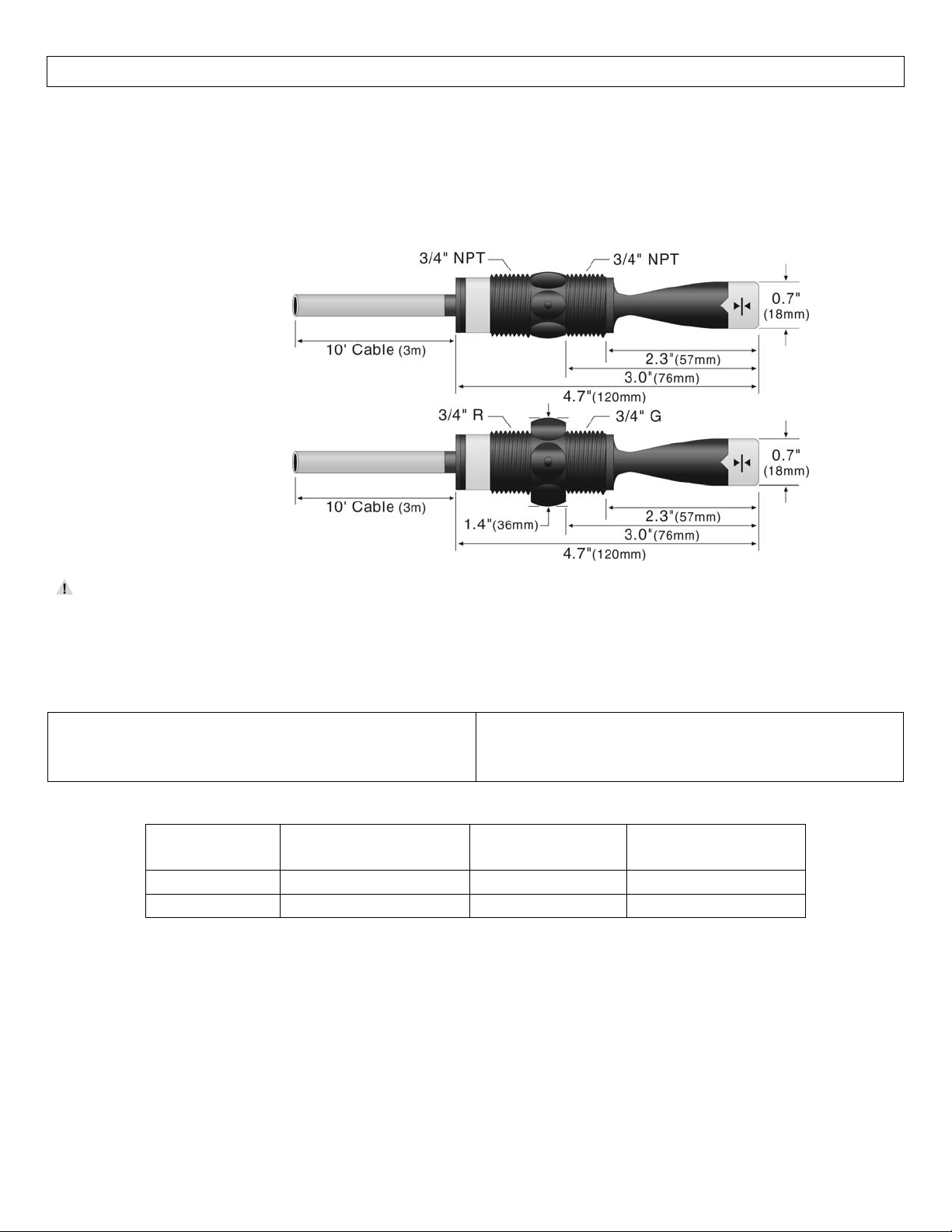
LTU‐101A‐R
LTU‐101A‐G‐R
Donotsqueezetheforkstogether.Doingsocoulddamageorbreakthesensorandvoidthewarranty.
WhenpoweringuptheLTU‐101Aseries,thestart‐upprocedurerequirestheswitchtocyclethroughawet
conditionfor1/2secondinordertodetermineaninitialresonance.
LTU‐101ASeriesSpecifications:
Sensormaterial: PPS(glassfill)
FKMcablegrommet
Maint.alarm: NPNtransistor,10mAmax.
Cablejacketmat’l: PP
Cabletype: 5‐conductor,#24AWG
(shielded)
Configurations:
PartNumber Material
(body)
Material
(cable)
Thread
(insidexoutside)
LTU‐101A‐R PolyphenyleneSulfide Polypropylene ¾”NPTx¾”NPT
LTU‐101A‐G‐R PolyphenyleneSulfide Polypropylene ¾”Rx¾”G
Note:alltuningforklevelswitchesareavailablewithlongerlengthscableof25’and50’.For25’ofcable,add
(‐25)totheend of thepartnumberandfor50’of cable,add(‐50)tothe endofthepartnumber.Example,
LTU‐101A‐R‐25willhave25’ofcable.
6
Page 7
SENSORINFORMATION(tuningfork) StepThree
Maintenance Alarm (LTU‐101A series Tuning Fork only):For optimum performance and proactive
maintenance, the sensor automatically adjusts for coating, and if necessary, outputs a preventative
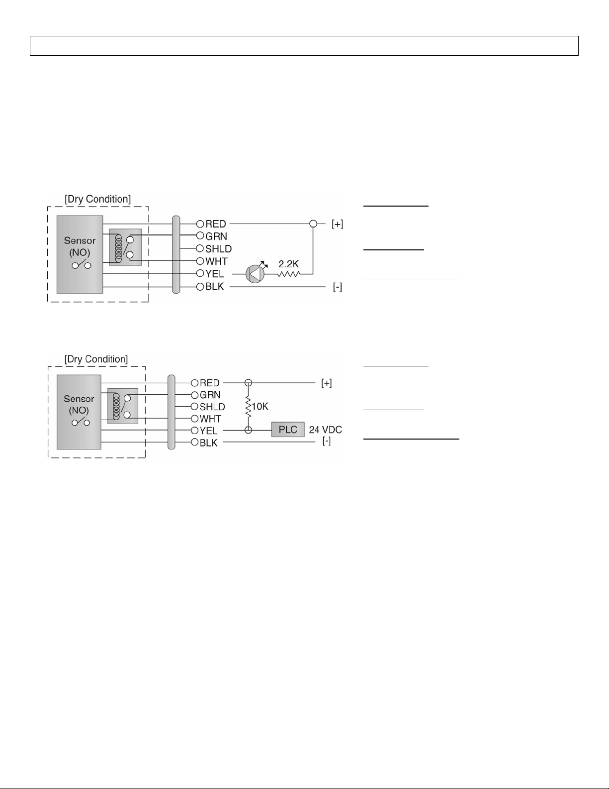
maintenance alarm.The Yellow wire is a NPN transistor designed to switch when a build‐up of material
preventsthetuningforkswitchfromoperatingatitsoperationalfrequency.UsetheYellow wire to identify
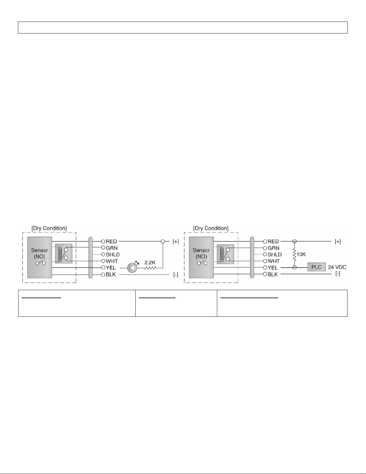
whentheTuning Fork switch requirescleaning.Towirethemaintenance output wire toan LED,followthe
wiringdiagrambelow.TheYellowwireisconnectedtotheLEDanda2.2kΩresistorinseriesandreferenced
backtothe(+)ofthepowersupply.
SensorPower
[RED&BLKwires]/36VDCMax.
8±1mADry/22±1mAWet
RelayRating
[GRN&WHTwires]/60VA
MaintenanceAlarm
[YELwire]/NPNTransistor/10mAMax.
TowirethemaintenanceoutputwiretoaPLC,followthewiringdiagrambelow.TheYellowwireisconnected
tothePLCinputwitha10kΩresistorparalleltothePLCinputandthe(+)ofthepowersupply.
SensorPower
[RED&BLKwires]/36VDCMax.
8±1mADry/22±1mAWet
RelayRating
[GRN&WHTwires]/60VA
MaintenanceAlarm
[YELwire]/NPNTransistor/10mAMax.
7
Page 8
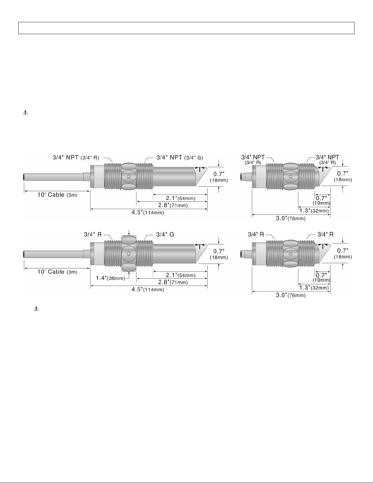
SPECIFICATIONS(optic) StepTwo
OpticLeakDetectionSwitch(LVF‐210Aseries):TheOpticLeakDetectoruseprinciplesofopticalrefractionto
detect the presence or absence of fluid.A pulsed infrared light beam is internally generated by a light
emittingdiodeandaimedattheslantedopticaltipofthesensor.Ifthetipisdry,thelightbeambouncesata
90degreeangletoareceivingphototransistor,indicatingadry condition.Ifthetipisimmersedinliquid,the
lightbeamwillrefractout into the liquid insteadof beingreflected tothe photo transistor,indicatingawet
condition.
The LVF‐210A series is designed as a leak detection switch.The switch should be installed in
applications where under normal conditions,it remains away from the liquid andwill only come into
contactduringaleak.
LVF‐212A‐R&LVF‐213‐R LVF‐210A‐R&LVF‐211A
‐R
LVF‐212A‐G‐R&LVF‐213‐G‐R LVF‐210A‐G‐R&LVF‐211A‐G‐R
The Optic Leak Detector cannot detect the presence orabsence of specular application liquids that
reflectlight(suchasmilk),orviscousliquids(suchaspaint)thatformacoatingonthesensortip.
8
Page 9

SPECIFICATIONS(optic) StepTwo
LVF‐210ASeriesSpecifications:
Sensormaterial:‐210A/‐212A:PP
‐211A/‐213A:PFA
Cablejacketmat’l:‐210A/‐212A:PP
‐211A/‐213A:PFA
Configurations:
Part
Number
Length
Material
(body)
Material
(cable)
Cableside
Sensorside
LVF‐210A‐R Short(3”) Polypropylene Polypropylene (3/4”NPT) (3/4”NPT)
LVF‐210A‐G‐R Short(3”) Polypropylene Polypropylene (3/4”R) (3/4”R)
LVF‐211A‐R Short(3”) PFA PFA (3/4”NPT) (3/4”NPT)
LVF‐211A‐G‐R Short(3”) PFA PFA (3/4”R) (3/4”G)
LVF‐212A‐R Long(4.5”) Polypropylene Polypropylene (3/4”NPT) (3/4”NPT)
LVF‐212A‐G‐R Long(4.5”) Polypropylene Polypropylene (3/4”R) (3/4”R)
LVF‐213A‐R Long(4.5”) PFA PFA (3/4”NPT) (3/4”NPT)
LVF‐213A‐G‐R Long(4.5”) PFA PFA (3/4”R) (3/4”G)
Note:allopticleakdetectionlevelswitchesareavailablewithlongerlengthscableof 25’and50’.For25’of
cable,add (‐25)totheendofthepartnumberandfor50’ofcable,add(‐50)totheendofthepartnumber.
Example,LVF‐210A‐R‐25willhave25’ofcable.
9
Page 10
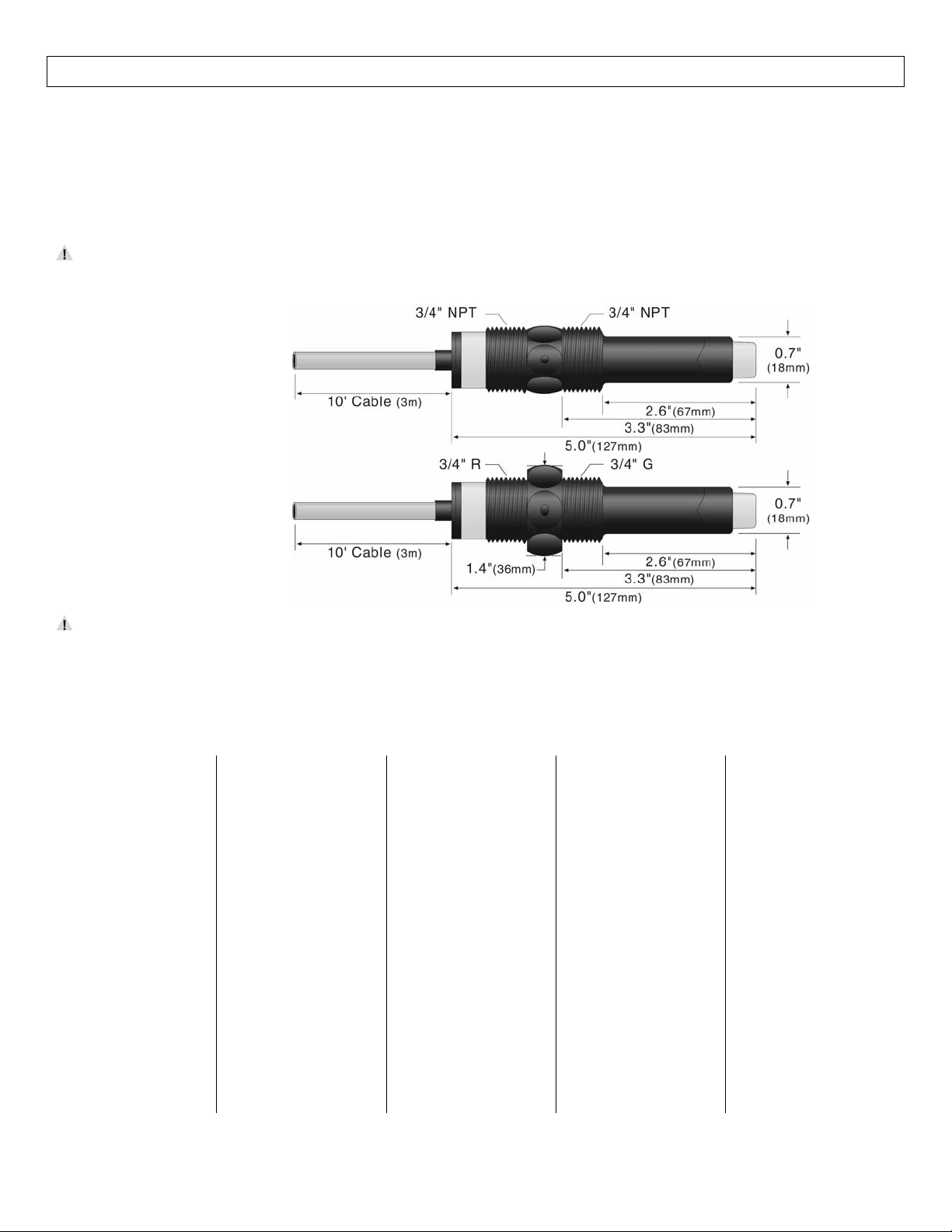
SPECIFICATIONS(capacitance) StepTwo
Capacitance Switch (LVC‐152series):The capacitance levelswitchgenerates a pulse‐waveradio frequency
signal from the capacitance electrode located in the sensing tip of each sensor. When liquid comes into
contact with the sensing tip, the capacitance as measured by the sensor changes based on the dielectric
constant of the liquid.The guard circuit rejects the negative effects of coating buildup on the probe by
eliminatingthecoatingsignalpathbetweentheactiveandreferenceelectrodes.
AvoidinstallingtheLVC‐152seriesinmetalfittingsandkeepthesensor6”awayfrommetalobjects.Itis
possibleforalargemetalobjecttoinfluencethesensor’soperation.
LVC‐152‐R
LVC‐152‐G‐R
The sensor’s operation may vary based on the dielectric properties of various application liquids. The
LVC‐152seriessensorisfactory‐calibratedtobeusedwithliquidswithadielectricvaluebetween20and
80.Liquidswithadielectricconstantlessthan20willnotbedetectedbyanLVC‐152seriessensor.
TableofCommonDielectricConstants:NOTE:Liquidswithadielectricconstantlessthan20willnotbe
detectedbyanLVC‐152serieslevelswitch.
Acetone ....................... 21
Acetoaldehyde ......... 22.2
Acetyl methyl hexyl
ketone ......................... 28
Alcohol .............. 16 to 31
Ammonia ........... 15 to 25
Acetic acid ....... 4.1 to 6.2
Butyl chloride ............ 9.6
Barium chloride ... 9 to 11
Benzene ..................... 2.3
Benzine ...................... 2.3
Barium nitrate ............ 5.6
Bromine ..................... 3.1
Chlorobenzene ... 4.7 to 6
Chlorotoluene ............ 4.7
Chloroform ...... 4.5 to 5.0
Chlorine, liquid ......... 2.0
Carbon tetrachloride . 2.2
Cyan .......................... 2.6
Cyclohexane methanol
................................... 3.7
D.I. Water .................. 20
Ethyl toluene ............. 2.2
Ethyl alcohol .............. 23
Ethylene glycol .......... 37
Ethylene oxide ........... 14
Ethylene dichlo ride
........................... 11 to 17
Ethylene chloride .... 10.5
Ethyl acetate ............. 6.4
Ethyl salicylate ......... 8.6
Ethyl stearate ............ 2.9
Ethyl silicote ............ 4.1
Formic acid ............... 59
Ferric oleate .............. 2.6
Freon ........................ 2.2
Glycerine ................... 47
Glycol ........................ 30
Glycol nitrite ............. 27
Gasoline ............ 2 to 2.2
Hydrochloric acid .... 4.6
Isobutyric acid .......... 2.7
Isobutyl methyl ketone
.................................... 13
Jet fuel ...................... 1.7
Lead carbonate .......... 18
Lead nitrate ............... 38
Methyl salicylate ...... 9.0
Methanol ..................... 33
Methyl alcohol .. 33 to 38
Margarine, liquid
.......................... 2.8 to 3.2
Methyl acetate ............7.3
N-butyl formate ..........2.4
Nitrobenzene ..... 26 to 35
Nitrotoluene ................ 25
Naphthalene ..... 2.3 to 2. 5
Oils, vegetable .................
Oils, mineral .... 2.3 to 2.4
Oils, petroleum .................
Oleic acid ....................2.5
Propane, liquid
......................... 1.8 to 1.9
Potassium nitrat e5.0 t o 5 .9
Potassium chloride ... 5.0
Stearic acid ................ 2.3
Toluene ..................... 2. 4
Trichloroethylene ..... 3.4
Trichloroacetic aci d .. 4.5
Terephthalic acid
.......................... 1.5 to 1.7
Thinner ...................... 3. 7
Urea ........................... 3.5
Vinyl chloride .... 2.8 to 6
Vinyl alcohol .. 1.8 to 2.0
Water, 20°C ............... 80
Water, 100°C ............. 48
10
Page 11

SPECIFICATIONS(capacitance) StepTwo
LVC‐152SeriesSpecifications:
Dielectricrange: >20constants
Conductiverange: >100miromhos
Sensormaterial: PP
Cablejacketmat’l: PP
Configurations:
Part
Number
Length
Material
(body)
Material
(cable)
Cableside
Sensorside
LVC‐152‐R Long(4.5”) Polypropylene Polypropylene (3/4”NPT) (3/4”NPT)
LVC‐152‐G‐R Long(4.5”) Polypropylene Polypropylene (3/4”R) (3/4”G)
Note:allcapacitancelevelswitchesareavailablewithlongerlengthscableof25’and50’.For25’ofcable,add
(‐25)totheend of thepartnumberandfor50’of cable,add(‐50)tothe endofthepartnumber.Example,
LVC‐152‐R‐25willhave25’ofcable.
TestingTip:TheLVC‐152seriessensorlooksforchangesincapacitancebaseduponthedielectricconstantof
theliquid.Althoughwaterhasahighdielectricconstant,thevolumeofa cupofwaterwillnot haveenough
changeincapacitancetoswitchthesensorintoawetcondition.Onewaytoincreasethecapacitanceforthe
cupofwateristodipyourfingerintothecup.Thevolumeofwaterwithinyourbodywilladdtothewaterin
thecupandwillresultinthesensoridentifyingawetcondition.
11
Page 12
SAFETYPRECAUTION StepThree
About Manual: PLEASE READTHEENTIRE MANUAL PRIORTOINSTALLING OR USINGTHISPRODUCT. This
manual includes information on all models of Omega EngineeringPowered LevelSwitches: LVU‐150 series,
LTU‐101Aseries,LVF‐210A seriesandLVC‐152series.Pleasereferto thepartnumberlocatedonthe sensor
labeltoverifytheexactmodelwhichyouhavepurchased.
User’sResponsibilityfor Safety:OMEGAENGINEERINGmanufacturesa widerangeofliquid levelswitches
andtechnologies.Whileeachofthetheseswitchesaredesignedtooperateinawidevarietyofapplications,
itistheuser’sresponsibilitytoselectaswitchmodelthatisappropriatefortheapplication,installitproperly,
perform tests of the installed system, and maintain all components. The failure to do so could result in
propertydamageorseriousinjury.
ProperInstallationandHandling:Becausethisisanelectricallyoperateddevice,onlyproperlytrainedstaff
shouldinstalland/orrepairthisproduct.Use a proper sealant with all installations.Never over tighten the
sensorwithinthefitting,beyondamaximumof80inch‐poundstorque.Alwayscheckforleakspriortosystem
start‐up.
Material Compatibility: The LVU‐150 series and LVF‐210A series sensors are available in two different
wetted materials.Models LVU‐150, LVU‐152, LVF‐210A and LVF‐212A are made of Polypropylene (PP).
ModelsLVU‐151,LVU‐153,LVF‐211AandLVF‐213AaremadeofPerfluoroalkoxy(PFA).TheLTU‐101Aseriesis
made of PPS (40%glass filled)and theLVC‐152 seriesis madeof PP.Makesure thatthe modelyou have
selected is compatible with the application liquid. To determine the chemical compatibility between the
sensoranditsapplicationliquids,refertoanindustryreferencesuchastheCompassCorrosion.
WiringandElectrical:Thesupplyvoltageusedtopowerthesensorshouldneverexceedamaximumof36
voltsDC(30VDCforLTU‐101Aseries).Electricalwiringofthesensorshouldbeperformedinaccordancewith
allapplicablenational,state,andlocalcodes.
Flammable, Explosive and Hazardous Applications:DONOT USE THE LVU‐150 SERIES,LTU‐101A SERIES,
LFV‐210ASERIESorLVC‐152SERIESGENERALPURPOSESWITCHINHAZARDOUSLOCATIONS.
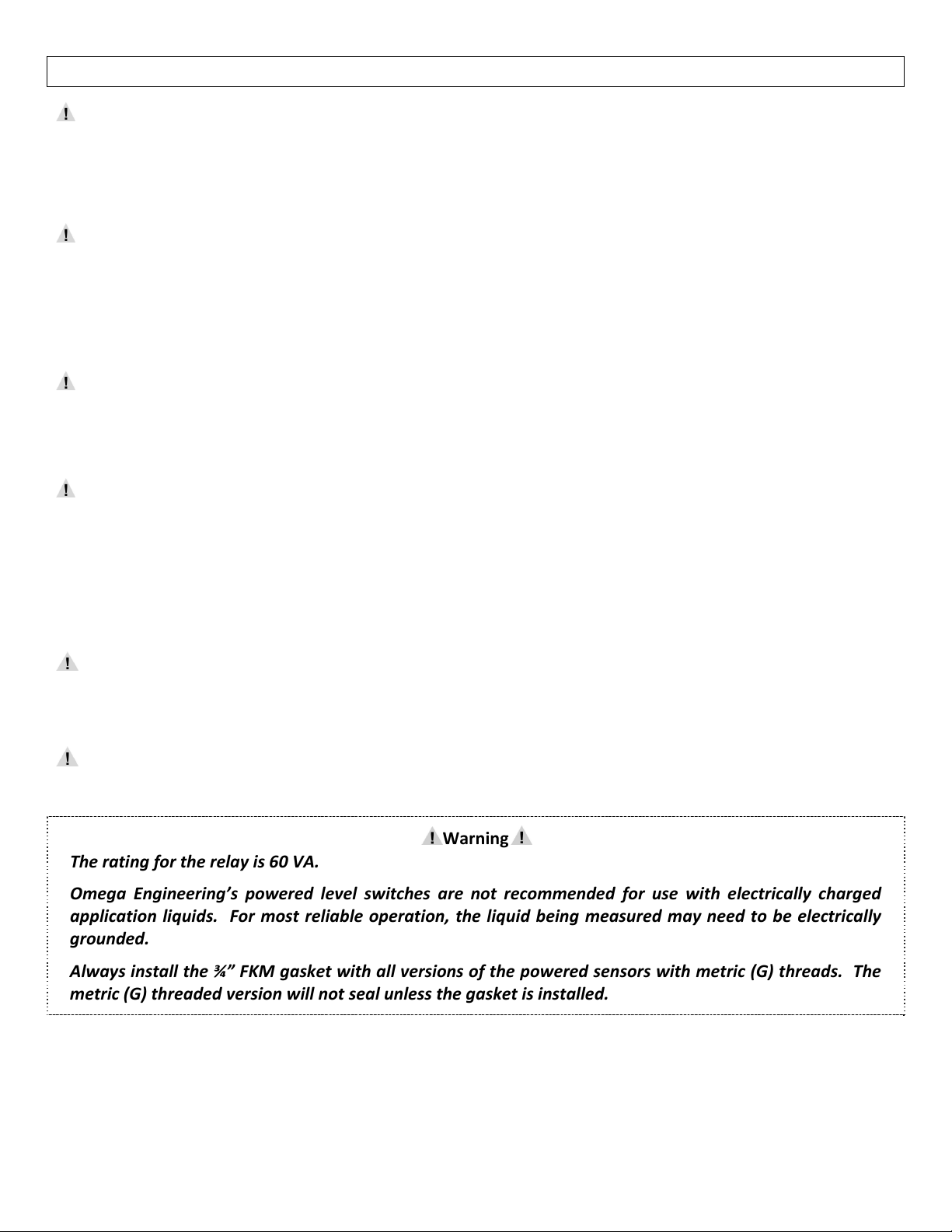
Warning
Theratingfortherelayis60VA.
Omega Engineering’s powered level switches are not recommended for use with electrically charged
application
liquids.For most reliable operation, the liquid beingmeasuredmayneedto be electrically
grounded.
Alwaysinstall the¾”FKMgasket withallversionsofthe poweredsensorswith metric(G)threads.The
metric(G)threadedversionwillnotsealunlessthegasketisinstalled.
12
Page 13

SAFETYPRECAUTION StepThree
MakeaFail‐SafeSystem:Designa fail‐safesystemthataccommodatesthepossibilityofswitchand/orpower
failure.OMEGAENGINEERINGrecommendstheuseofredundantbackupsystemsand alarms in addition to
the primary system.Adding a redundant high level float switch to the system is a cost effective meansto
preventcostlytankoverflows.
Allofthepoweredlevelsensorshaveasingleinternalrelay.Thenormallyopen(NO)ornormallyclosed(NC)
operation is user selected based on the desired system control.Always design a fail‐safe system that
accommodatesfor thepossibility of functionaland/or powerfailure to theinstrument.The "normal" relay
stateiswheretherelaycoilisde‐energizedandtherelayindicatorisOFF.Therefore,ifpoweriscutOFFtothe
switch it will de‐energizethe relay.Make surethat the de‐energized state is the safe state inyour system
design.Assuch,ifswitchpowerislost,apumpwillturnOFFifitisconnectedtothenormallyopensideofthe
relay.
13
Page 14
INSTALLATION StepFour
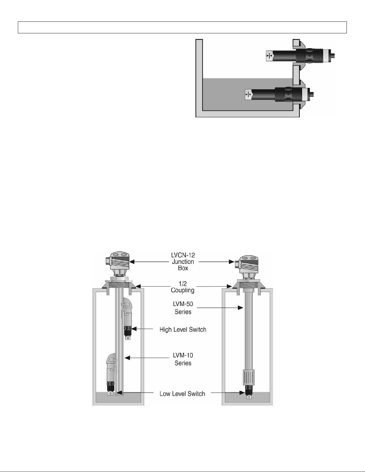
Through Wall Installation:Omega Engineering’s
poweredlevel switches may be installedthrough the
top, side or bottom of a tank wall.The sensor has
male 3/4" NPT (R/G) threads on either side of a
15/16" wrench flat.This enables the user to select
the sensor’s mounting orientation, installed outside
ofthetankin,orinsideofthetankout.
TopWall Installation:Thepoweredlevel switches may be installed throughthe topwall ofatank.Omega
Engineering’sleveltrackmountingsystemLVM‐10seriesisanin‐tankfittingwhichenablesuserstoinstallup
tofourOMEGAENGINEERINGsensorsofanytechnology,toanydepth,alongtheentirelengthoftrack.The
LVM‐10seriesmaybeinstalledthroughthetopwallofanytankusingastandard2"NPTtankadapter.Ifno
tanktopinstallationisavailable,OmegaEngineering'ssidemountbracket,LVM‐30,enablestheLVM‐10series
tobeinstalleddirectlytothesidewallofatank.DonotusethePFAbodiedsensorswithLVM‐10series.
OmegaEngineering’s LVM‐50 seriesleveltrack mounting systemisanin‐tank fitting whichenablesusers to
install one OMEGA ENGINEERING sensor, of any technology, to a specific depth.The Omega Engineering
sensormaybeinstalledontothe3/4"NPTadapterattheendoftheLVM‐50series.TheLVM‐50seriesmaybe
installedthrough the topwallof any tankusinga standard 2" NPTtank adapter.OmegaEngineering'sside
mountbracket,modelLVM‐30,mayalsobeusediftopwallinstallationisnotavailable.
14
Page 15
ELECTRICAL StepFive
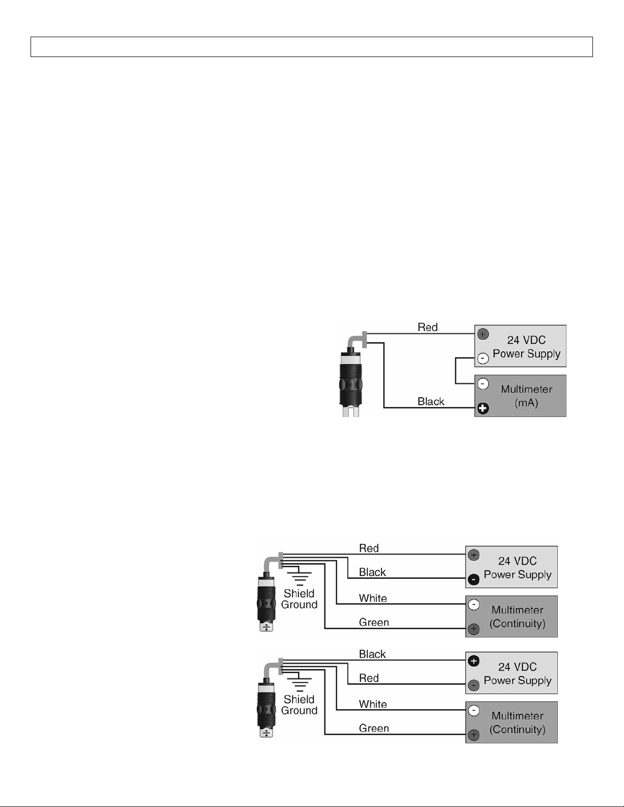
SupplyVoltage:Thesupplyvoltagetothepowered levelswitchshouldneverexceedamaximumof36VDC
(30VDCwithLTU‐101Aseries).Omega Engineering controllershaveabuilt‐in13.5VDCpowersupplywhich
providespowertoallofOmegaEngineering’selectricallypoweredsensors.Alternativecontrollersandpower
supplies, with a minimum output of 12 VDC up to a maximum output of 36 VDC (30 VDC with LTU‐101A
series),mayalsobeusedwiththepoweredlevelswitch.
Required Cable Length:Determinethe length ofcable requiredbetween the powered level switchand its
pointoftermination.Allowenough slack toensuretheeasyinstallation,removal and/or maintenanceofthe
sensor.The cable lengthmaybe extended uptoa maximum of1000 feet, usingawell‐insulated, 14 to20
gaugeshieldedfourconductorcable.
WireStripping:Usinga10gaugewirestripper,carefullyremovetheouterlayer
ofinsulationfromthelast1‐
1/4"ofthesensor'scable.Unwrapanddiscardtheexposedfoilshieldfromaroundthe signal wires,leaving
the drain wire attached if desired. With a 20 gauge wire stripper, remove the last 1/4" of the colored
insulationfromthesignalwires.
Signal Outputs
(Current sensing):The standard
method used by Omega Engineeringcontrollers; this
technology uses onlytwowires (Red andBlack).The
sensordraws5mAwhenitisdry(8mAwithLTU‐101A
series),and22mAwhenwet.NC/NOstatusmustbe
setbythecontroller.TheWhiteandGreenwiresare
notused.
SignalOutput (Relayswitching):Allowsthesensortoswitchasmallloadonoroffdirectly,usinganinternal
1Arelay(60VAC/60VDC).Thesensorusestherelayandfeatures4wires(red,black,whiteandgreen)anda
shieldwire.TheNO/NCstatusisset bythepolarityofthevoltagefeedingtheredandblackwires.Thegreen
wireisthe common for therelay andthewhitewireis the NO orNC,dependingonthe polarity ofredand
black.
NormallyOpenWiring:
NormallyClosedWiring:
15
Page 16
WIRING StepSix
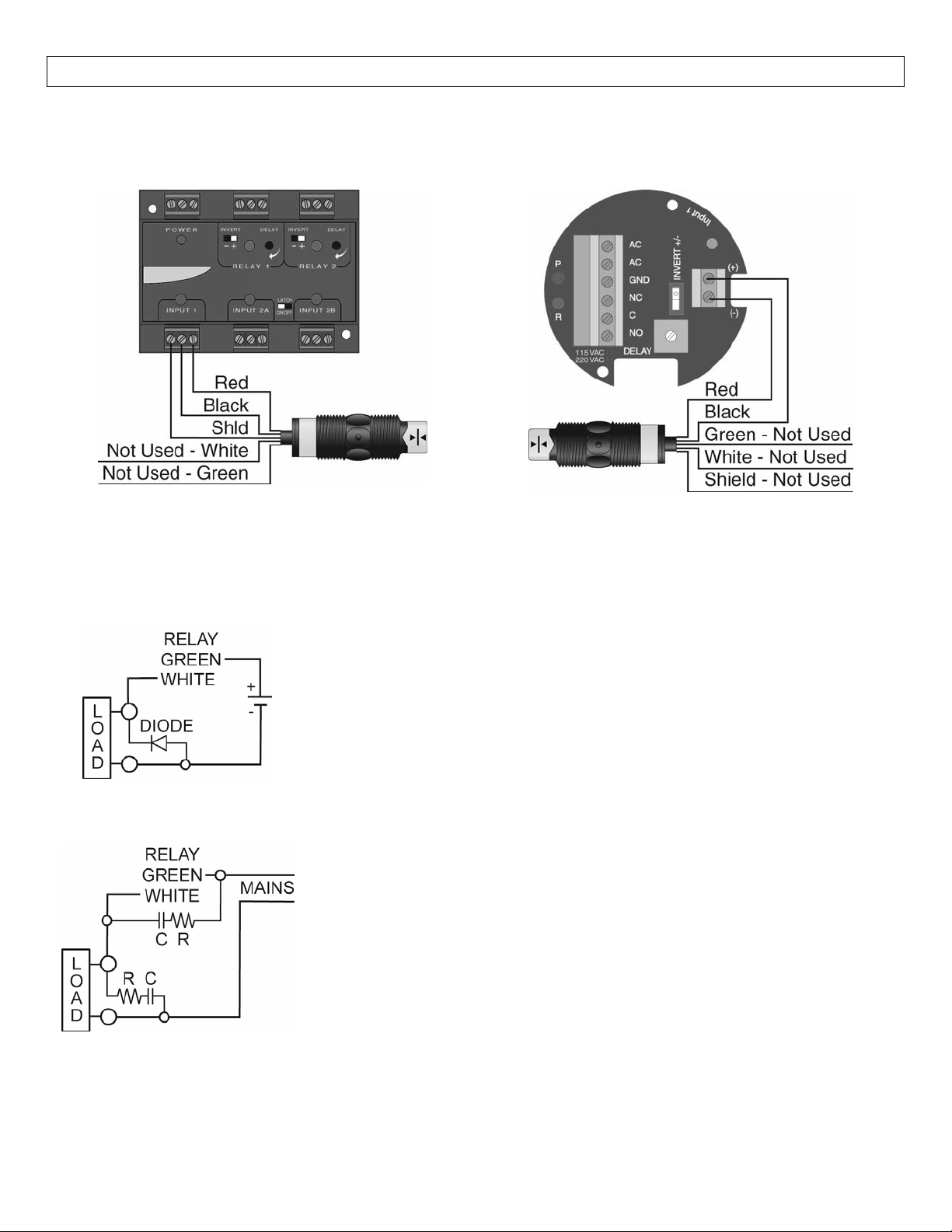
WiringtoaOMEGAENGINEERINGController
LVCN‐120SeriesController(4or20mAoutput):
LVCN‐120Shown
LVCN‐100SeriesController(4or20mAoutput):
LVCN‐20shown
Switching Inductive Loads:The use of suppressors (snubbers) is strongly recommended when switching
inductiveloadstopreventdisruptingthemicroprocessor’soperation.Thesuppressorsalsoprolongthelifeof
therelaycontacts.SuppressioncanbeobtainedwithacatchdiodeforDCcircuitsandaresistor‐capacitor(RC)
forACcircuits.
CatchDiode
Alwaysusestepper relays betweenthesensorandexternalloads.
ForDCcircuitsuseacatchdiodesuchas1N4148,shownonleft.
RefertothefollowingcircuitsforRCnetworkassemblyandinstallation:
ChooseRandCasfollows:
R:0.5to1Ohmsforeachvoltacrossthecontacts
C:0.5to1μFforeachampthroughclosedcontacts
Notes:
1. Usecapacitorsratedfor250VAC.
2. RCnetworksmayaffectloadreleasetimeofsolenoidloads.Check
toconfirmproperoperation.
3. InstalltheRCnetworkatthemetersrelayscrewterminals.AnRC
networkmayalsobeinstalledacrosstheload.Experimentforbest
results.
16
Page 17
WIRING(continued) StepSix
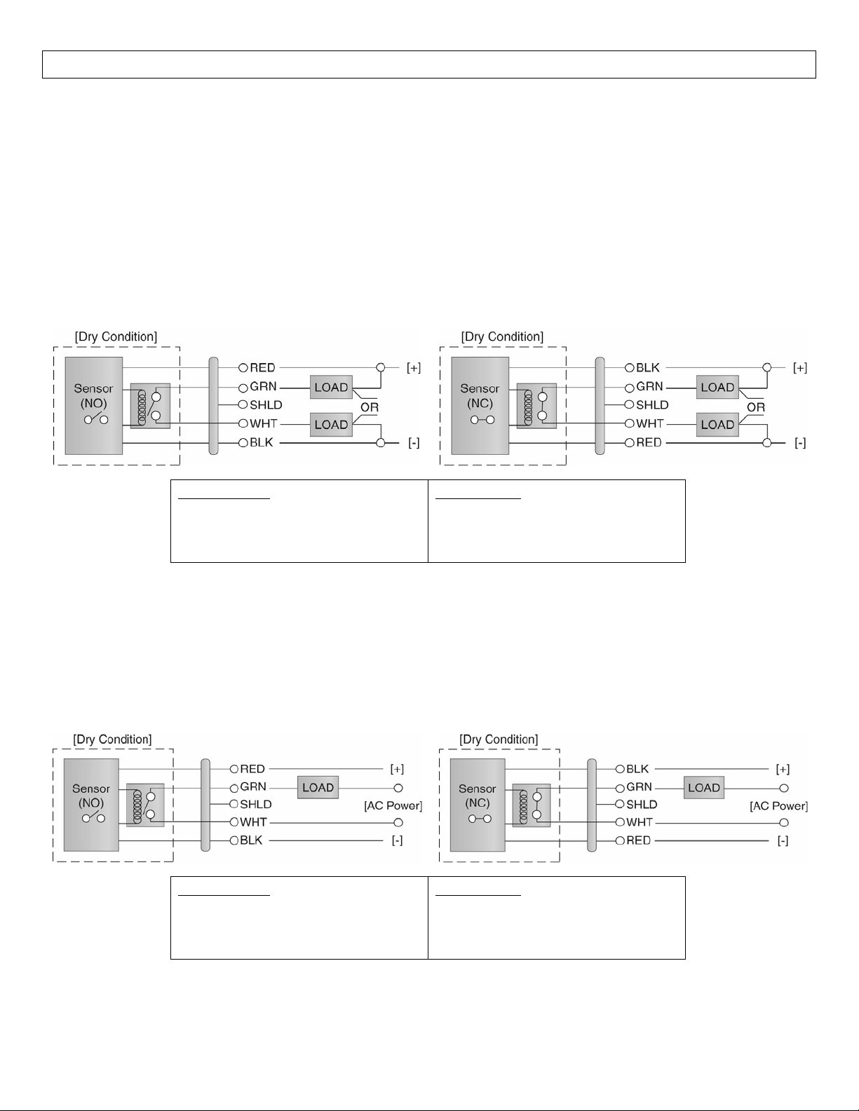
Wiring the Relay Output:The sensor requires 12‐36 VDC (30 VDC max. for LTU‐101A series) power to
operate the sensor and switch the relay.All illustrations below identify a Dry switch state as the normal
positionoftherelay.
SwitchingaNormallyOpenDCLoad:
The Red wire connects
to Positive (+) of the power
supply and the Black wire connects to Negative (‐).
The LOAD can be attached to either the Green or
Whitewires.Completethecircuit by connecting the
Green to (+) VDC power or White to (‐) VDC power
(seeillustrationbelow).
SensorPower
[RED&BLKwires]/36VDCMax.
5±1mADry/22±1mAWet
8±1mADry(LTU‐101Aseriesonly)
SwitchingaNormallyClosedDCLoad:
The Black wireconnects to Positive(+) of thepower
supplyandtheRedwireconnectstoNegative(‐).The
LOAD can be attachedto eitherthe Greenor White
wires.Completethecircuitby connecting the Green
to (+) VDC power or White to
(‐) VDC power (see
illustrationbelow).
RelayRating
[GRN&WHTwires]/60VA
SwitchingaNormallyOpenACLoad:
TheRedwireconnectstoPositive(+)oftheDCpower
supply and the Black wire connects to Negative (‐).
TheLOADcanbeattachedtotheGreenwireandthe
Hot of the VAC power.Connect the White to the
Neutralof
theVACpower(seeillustrationbelow).
SensorPower
[RED&BLKwires]/36VDCMax.
SwitchingaNormallyClosedACLoad:
The Black wire connects to Positive (+) of the DC
powersupplyandtheRedwire connectstoNegative
(‐).TheLOADcanbeattachedtotheGreenwireand
theHotoftheVACpower.Connectthe
NeutraloftheVACpower(seeillustrationbelow).
RelayRating
[GRN&WHTwires]/60VA
5±1mADry/22±1mAWet
8±1mADry(LTU‐101Aseriesonly)
Whitetothe
17
Page 18
WIRING(continued) StepSix
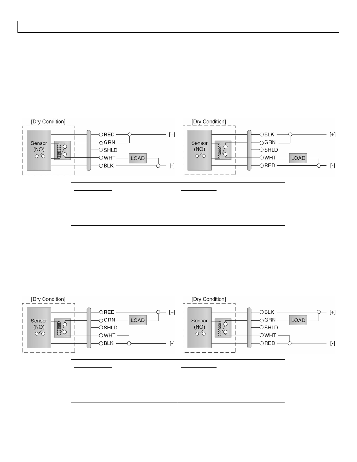
Wiring as a P‐Channel or N‐Channel output:The sensor can be substituted for either a P‐Channel (PNP,
sourcing)outputoraN‐Channel(NPN,sinking)output.
NormallyOpenDCLoadasaP‐ChannelOutput:
The Red wire connects to Positive (+) of the power
supply and the Black wire connects to Negative (‐).
The Green wireis jumped tothe Red wire while the
White wire is connected to the LOAD.Jumper the
LOADtotheNegative(‐)tocompletethecircuit.
SensorPower
[RED&BLKwires]/36VDCMax.
(30VDCMax.forLTU‐101Aseries)
5±1mADry/22±1mAWet
8±1mADry(LTU‐101Aseriesonly)
NormallyClosedDCLoadasaP‐ChannelOutput:
The Black wireconnects to Positive(+) of thepower
supplyandtheRedwireconnectstoNegative(‐).The
Green wire is jumped to the Black wire while the
White wire is connected to the LOAD.Jumper the
LOADtotheNegative(‐)tocompletethecircuit.
RelayRating
[GRN&WHTwires]/60VA
NormallyOpenDCLoadasaN‐ChannelOutput:
The Red wire connects to Positive (+) of the power
supply and the Black wire connects to Negative (‐).
TheWhitewireisjumpedtotheBlackwirewhilethe
Green wire is connected to the LOAD.Jumper the
LOADtothePositive(+)tocompletethecircuit.
NormallyClosedDCLoadasaN‐ChannelOutput:
The Black wireconnects to Positive(+) of thepower
supplyandtheRedwireconnectstoNegative(‐).The
WhitewireisjumpedtotheRedwirewhiletheWhite
wireisconnectedtotheLOAD.Jumper the LOAD to
thePositive(+)tocompletethecircuit.
SensorPower
[RED&BLKwires]/36VDCMax.
RelayRating
[GRN&WHTwires]/60VA
(30VDCMax.forLTU‐101Aseries)
5±1mADry/22±1mAWet
8±1mADry(LTU‐101Aseriesonly)
18
Page 19
MAINTENANCE StepSeven
General:The powered levelswitch requires no periodic maintenanceexcept cleaning as required. Itis the
responsibility of the user to determine the appropriate maintenance schedule, based on the specific
characteristicsoftheapplicationliquids.
Cleaningprocedure:
1. Power:Makesurethatallpowertotheswitch,controllerand/orpowersupply
isdisconnected.
2. Switch removal: In all through‐wall installations, make surethat the tank is drained well below the
sensorpriortoremoval.Carefully,removethesensorfromtheinstallation.
3. Cleaning the switch:Use a soft bristle brush and mild detergent, carefully wash the level switch.Do
not
useharshabrasivessuchassteelwoolorsandpaper,whichmightdamagethesurfacesensor.Do
notuseincompatiblesolventswhichmaydamagethesensor'sPP,PFA,PVDForPPSplasticbody.
4. Sensorinstallation:FollowtheappropriatestepsofinstallationasoutlinedintheInstallation.
MaintenanceOutputtoLED(LTU‐101Aseries only):
To wire the maintenance output wire to an LED,
followthewiring diagrambelow.TheYellowwireis
connected to theLED anda2.2kΩ resistorin series
andreferencedbacktothe(+)ofthepowersupply.
MaintenanceOutputtoPLC(LTU‐101Aseries only):
Towirethemaintenance output wire to aPLC, follow
the wiring diagram below.The Yellow wire is
connected to the PLC input with a 10 kΩ resistor
parallel to the PLC input and the (+) of the power
supply.
SensorPower
[RED&BLKwires]/30VDCMax.
8±1mADry/22±1mAWet
RelayRating
[GRN&WHTwires]/60
VA
MaintenanceAlarm
[YELwire]/NPNTransistor/10mAMax.
19
Page 20
MAINTENANCE(continued)StepSeven
Testingtheinstallation:
1. Power:Turnonpowertothecontrollerand/orpowersupply.
2. Immersing the switch: Immerse the sensing tip in its application liquid, by filling the tank up to the
switchespointofactuation.Analternatemethodistoholdacupfilledwithliquidup totheswitch'stip.
3. Test: Withthe switchbeing fluctuatedbetween wet anddry states,the switch indicatorlight in the
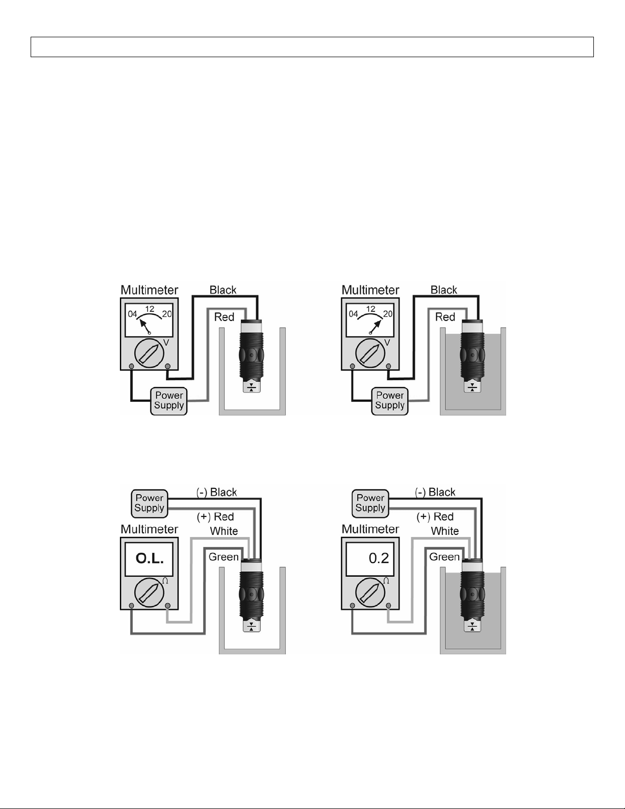
controllershouldturnonandoff.Ifthecontrollerdoesn'thaveaninputindicator,useavoltmeteror
ammetertoensurethattheswitchproducesthecorrectsignal(seebelow).
4. Point of actuation: Observe the point at which the rising or falling fluid level causes the switch to
changestate,andadjusttheinstallationoftheswitchifnecessary.
Example:TestingtheLVU‐150serieswithaMultimetersettoreadcurrent(mA).WhenwiredNO[Redto(+)],
themeterwillread5mA,±1mAwhendryandwillread20mA,±1mAwhenwet.
Example:TestingtheLVU‐150serieswithamultimetersettoreadresistance(ohms).WhenwiredNO[Redto
(+)],themeterwillreadO.Lwhendryandwillreadsomesmallamountofresistance(ex.0.2Ohms)whenwet.
20
Page 21

21
Page 22

22
 Loading...