

Page 1
EchoPro®
Intrinsically Safe Radar Level Transmitter
LR11, LR16, LR21, LR26 & LR31 Series Manual
Flowline, Inc. | 10500 Humbolt Street, Los Alamitos, CA 90720 p 562.598.3015 f 562.431.8507 w flowline.com MN301900 Rev B
Page 2

Introduction / Table of Contents Step One
TABLE OF CONTENTS Page
Section One | Introduction: .............................................................................................................................. 2
Table of Contents: ................................................................................................................................... 2
Sensor Models: ....................................................................................................................................... 5
Operating Principle: ................................................................................................................................. 6
Features: ................................................................................................................................................. 6
Benefits: .................................................................................................................................................. 6
Limitations: .............................................................................................................................................. 6
Specifications: ......................................................................................................................................... 7
Intrinsically Safe Control Drawings: ........................................................................................................ 12
Labels for Intrinsic Safety: ...................................................................................................................... 13
Dimensions: ........................................................................................................................................... 14
Safety Precautions: ............................................................................................................................... 17
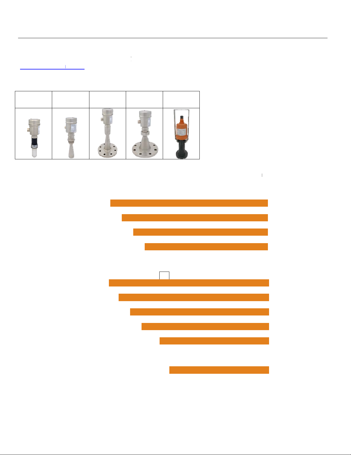
Section Two | Getting Started: ....................................................................................................................... 18
Setup Overview: .................................................................................................................................... 18
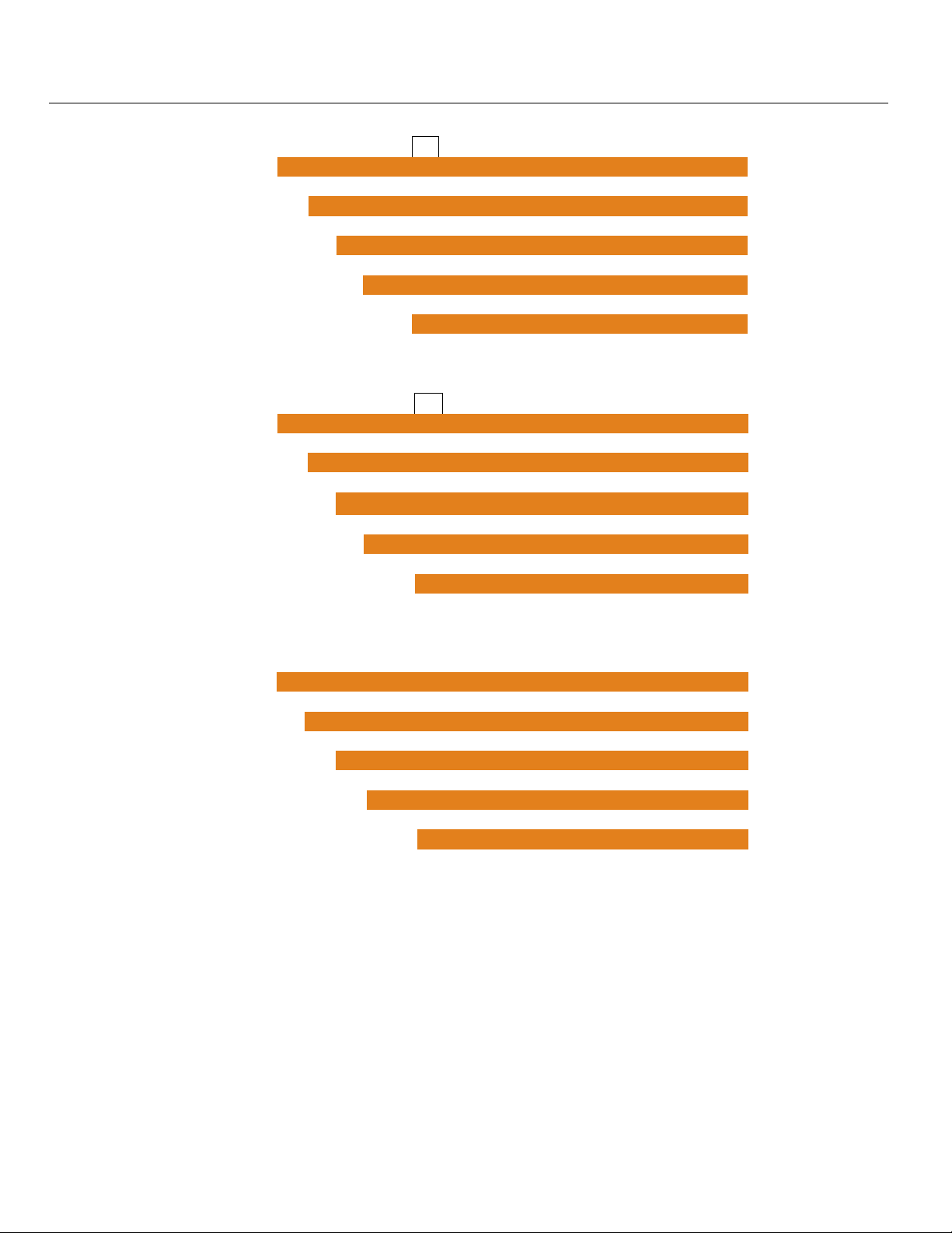
Part Number: ......................................................................................................................................... 20
Section Three | Install Sensor: ....................................................................................................................... 22
Installation Requirements: ..................................................................................................................... 22
FCC Conformity: ..................................................................................................................................... 23
LR16 Antenna Preparation: ................................................................................................................... 24
Mounting Position: ................................................................................................................................. 25
Flange Riser Installation: ....................................................................................................................... 28
Beam Angle: .......................................................................................................................................... 29
Stand Pipe Installation: .......................................................................................................................... 30
Bypass Installation: ............................................................................................................................... 31
LR31 Sensor Installation: ...................................................................................................................... 32
LR98 Display Installation: ...................................................................................................................... 33
Section Four | Wire Sensor: ........................................................................................................................... 34
Terminal Wiring: .................................................................................................................................... 34
HART
HART
Standard vs Multidrop: ........................................................................................................................... 35
LR31 configuration: ................................................................................................................................ 36
LR31 Wiring and Description: ................................................................................................................. 36
USING LR98 DISPLAY AS HMI FOR LR31 SERIES: ............................................................................ 37
Wiring to Displays, Controllers & PLCs: ................................................................................................ 38
®
Wiring: ........................................................................................................................................ 35
®
Device descriptors (DD files): .................................................................................................... 35
| 2 MN301900 Rev B
Page 3

Introduction / Table of Contents (continued) Step One
Section Five | Configuration Using Display: ................................................................................................. 40
Basic Configuration Overview: .............................................................................................................. 40
Basic HART communicator overview: .................................................................................................... 41
Units of Measurement: ................................................................................................................ 42
Sensor Height: ............................................................................................................................ 42
Fill-Height:................................................................................................................................... 43
Maximum Range:........................................................................................................................ 43
Dead Band: ................................................................................................................................. 44
Echo Curve: ................................................................................................................................ 44
Using the Display: ................................................................................................................................. 45
Changing Display Values: ..................................................................................................................... 46
Step 1 - Measure the Tank: ................................................................................................................... 47
Step 2 - Set the Units of Measurement: ................................................................................................ 48
Step 3 - Set the Sensor Height (4mA): .................................................................................................. 49
Step 4 - Set the Fill-Height (20mA): ....................................................................................................... 50
Step 5 - Set the Range (Maximum Range): .......................................................................................... 51
Step 6 - Set the Dead Band: ................................................................................................................. 52
Step 7 - Check the Echo Curve: ............................................................................................................ 53
Section Six | Process Adjustments: .............................................................................................................. 54
Process Adjustments Overview: ............................................................................................................ 54
Fast Filling or Emptying of Liquid: .............................................................................................. 55
Liquid Requiring First Echo Adjustment: ..................................................................................... 56
Liquid Surface is Turbulent or Agitated: ..................................................................................... 57
Foam on the Surface of the Liquid: ............................................................................................ 58
Liquids with Low Dielectric: ......................................................................................................... 59
Sensor Installed in a Stand Pipe or Sight Glass: ....................................................................... 60
Section Seven | Advanced Adjustments: ...................................................................................................... 61
Advanced Adjustments Overview: ......................................................................................................... 61
4-20mA Reverse Output: ....................................................................................................................... 62
Fail-Safe Output: ................................................................................................................................... 63
Minimum Current Output: ...................................................................................................................... 64
HART
Create a New False Echo Curve: .......................................................................................................... 66
Update an Existing False Echo Curve: .................................................................................................. 67
Section Eight | Troubleshooting: .................................................................................................................... 68
Troubleshooting Overview: .................................................................................................................... 68
Measurement Status: ............................................................................................................................ 69
Peak Values: ......................................................................................................................................... 70
Simulation: ............................................................................................................................................. 71
First Echo Adjustment: .......................................................................................................................... 72
Echo Curve Zoom: ................................................................................................................................ 73
False Echo Curve Delete: ..................................................................................................................... 74
Reset: .................................................................................................................................................... 75
®
Operation Mode: ....................................................................................................................... 65
MN301900 Rev B 3 |
Page 4

Introduction / Table of Contents (continued) Step One
Section Nine | Appendix: ................................................................................................................................. 76
Configuration Menu: .............................................................................................................................. 76
Empty Configuration: ............................................................................................................................. 77
Full Configuration: ................................................................................................................................. 77
Medium: ................................................................................................................................................. 78
Liquid Medium: ........................................................................................................................... 78
Solids Medium: ........................................................................................................................... 79
Low Dielectric Medium: .............................................................................................................. 80
Dampen: ................................................................................................................................................ 80
Scaled Units: ......................................................................................................................................... 81
Range: ................................................................................................................................................... 81
Dead Band: ........................................................................................................................................... 81
Display Menu: ........................................................................................................................................ 82
Display Value: ....................................................................................................................................... 82
LCD Contrast: ........................................................................................................................................ 82
Diagnostics Menu: ................................................................................................................................. 83
Peak Values: ......................................................................................................................................... 83
Measurement Status: ............................................................................................................................ 83
Echo Curve: ........................................................................................................................................... 84
Simulation: ............................................................................................................................................. 84
Service Menu: ....................................................................................................................................... 85
False Echo: ........................................................................................................................................... 86
Output Settings: ..................................................................................................................................... 86
Reset: .................................................................................................................................................... 87
Units of Measurement: .......................................................................................................................... 87
Language: ............................................................................................................................................. 87
HART
Information: ........................................................................................................................................... 88
Factory Settings: ................................................................................................................................... 89
User Configuration: ............................................................................................................................... 89
Troubleshooting: ..................................................................................................................................... 90
Section Ten | Warranty, Returns and Limitations: ........................................................................................ 92
Warranty: ............................................................................................................................................... 92
Returns: .................................................................................................................................................. 92
Limitations: ............................................................................................................................................. 92
®
Operational Mode: ..................................................................................................................... 87
| 4 MN301900 Rev B
Page 5
Introduction / Table of Contents (continued) Step One
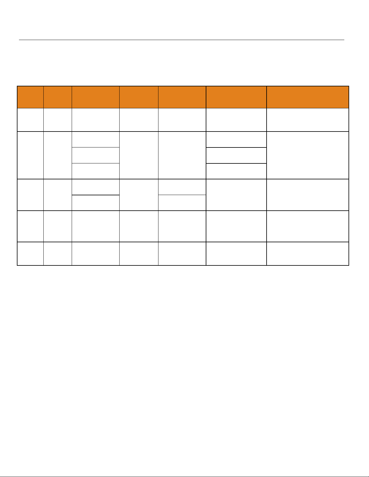
SENSOR MODELS
Offered in eight different models, EchoPro® is an intrinsically safe, two-wire, pulse radar level sensor that
provides a continuous 4-20 mA current output that’s proportional to the liquid level in a tank or sump. Make
sure that the model purchased is appropriate for your application.
Series
LR11
LR16
LR21
LR26
LR31
Max.
Range
32.81’
(10m)
98.42’
(30m)
65.61’
(20m)
114.83’
(35m)
98.42’
(30m)
Beam Angle Material Mounting
22° PFA 1-1/2” NPT
18° (2” horn)
12° (3” horn)
316L SS 1-1/2” NPT
8° (4” horn)
12°
(3” Flange)
8°
(4” flange)
20°
316L SS
with PTFE
cover
316L SS
with PTFE
cover
3” ANSI
flange
4” ANSI
flange
4” ANSI
flange
6” ANSI
flange
Bracket or
12° PA66
top mounted
(1”) conduit
FCC
Compliance
Part 15.209,
Class A
Part 15.209,
Class A
Part 15.256,
Class B
Part 15.256,
Class B
Part 15.256,
Class B
Part 15.209,
Class A
Part 15.256,
Class B
Application
Corrosive liquids under
simple process
conditions
Storage tanks & process
tanks under difficult
process conditions
Aggressive liquids under
extremely difficult
process conditions
Storage tank & process
tanks under extremely
difficult process
conditions
Water processing, lift
stations, storm water and
sump process conditions
MN301900 Rev B 5 |
Page 6

Introduction / Table of Contents (continued) Step One
OPERATING PRINCIPLE
The sensor emits a microwave pulse from its antenna, which travels at the speed of light to the surface of the
medium below. A portion of that energy reflects off the medium and returns to the antenna. The time gap
between energy emission and receipt is called the “time of flight”, and is proportional to the distance between
the medium surface and the sensors measurement location, as at the bottom of the antenna. The sensor
measures the time of flight and translates this value into a continuous 4-20mA signal output that’s proportionate
to level within a defined measurement span.
FEATURES
Easy configuration with LCD push button display module
Adjustable loop fail-safe, no change, 20.5 mA, 22 mA
Small 12” (30.48cm) dead band enables full tank measurement
Recognition, storage and deletion of false echo signal returns
BENEFITS
Unaffected by physical process and environmental conditions
Ideal for applications with higher temp, pressure, foam, vapor and vacuum
Strong signal penetrability with minimal attenuation over distance
LIMITATIONS (FACTORS THAT COULD INFLUENCE PERFORMANCE)
Air particulates with a high dielectric constant value such as lead or ferroalloy
Highly dense air particulates that attenuate microwave emission and receipt
Material build-up on the antenna that degrades microwave emission and receipt
Mediums that have an extremely low dielectric constant value with little reflectivity
| 6 MN301900 Rev B
Page 7
Introduction / Table of Contents (continued) Step One
SPECIFICATIONS
Measurement Range: LR11: .. 32.81 feet (10m) LR16: 98.42 feet (30m)
(maximum) LR21: 65.51 feet (20m) LR26: 114.83 feet (35m)
LR31: .. 98.42 feet (30m)
Dead Band: 12” (30.48cm) / Factory Set -
Note: Can be lowered to 2” from the bottom of the antenna
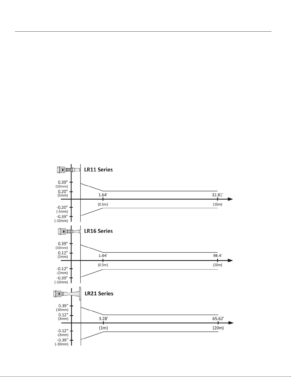
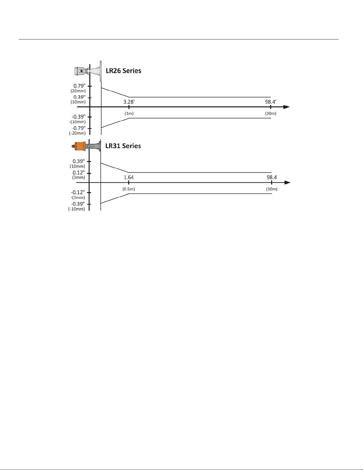
Measurement Accuracy: LR11: .. ±5 mm LR16: ±3mm
(see charts on pages 8 & 9) LR21: ±3mm LR26: ±10mm
LR31: ±3mm
Display Resolution: 1 mm
Frequency Range: 26 GHz: LR11, LR16, LR21 & LR31 series
6.3 GHz: LR26 series only
Measurement Interval: About 1 sec (dependent on configuration settings)
Adjustment Time: About 1 sec (dependent on configuration settings)
Beam Angle: LR11: 22° LR21: 12° - 3” ANSI Flange
LR16: 18° - 2” (48mm) Horn 8° - 4” ANSI Flange
12° - 3” (78mm) Horn LR26: 20°
8° - 4” (98mm) Horn LR31: 12°
Process Connection: LR11: 1-½” NPT LR26: 4” ANSI Flange
LR16: 1-½” NPT 6” ANSI Flange
LR21: 3” ANSI Flange LR31: Bracket or top
4” ANSI Flange mount (1”) NPT
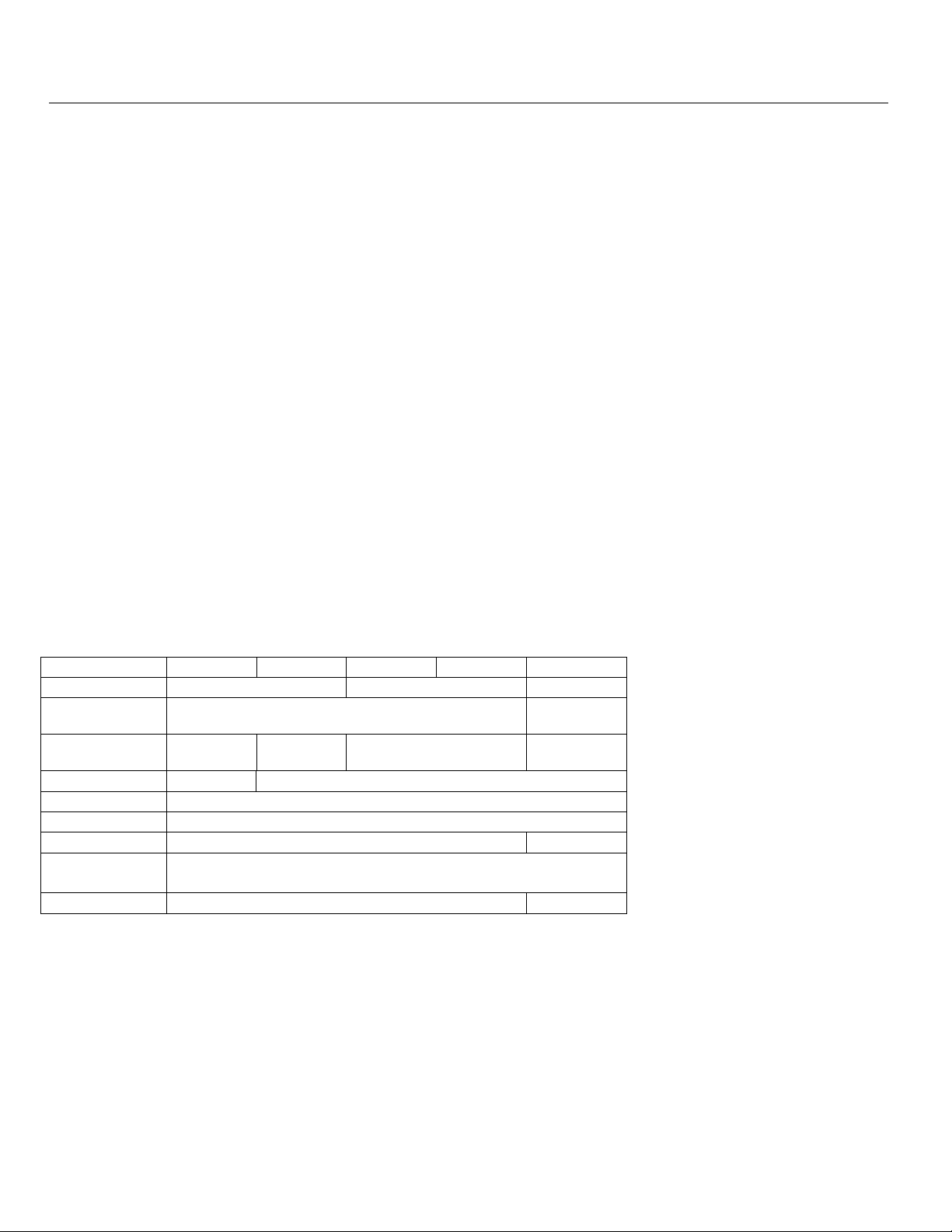
Material:
Series LR11 LR16 LR21 LR26 LR31
Flange
Enclosure
Antenna
Extension
Seal
Seal Ring
Window
Ground
Terminal
Bracket
PBT-FR N/A
N/A 316L SS N/A
316L SS
PFA 316L SS
Silicone (between housing and cap)
Polycarbonate N/A
316L SS with PTFE
Cover
Viton®
Stainless Steel
N/A 316 SS
PA66
(Nylon)
PA66
(Nylon)
MN301900 Rev B 7 |
Page 8
Introduction / Table of Contents (continued) Step One
Weight: LR11: 2.20 lbs (1kg) LR16: 4.41 lbs (2kg)
Depends on process LR21: 6.61 lbs (3kg) LR26: 6.61 lbs (3kg)
connection size and LR31: 2.20 lbs (1kg)
housing configuration
Temperature (Process): LR11: F: -40° to 266° LR16: F: -76° to 302°
C: -40° to 130° C: -60° to 150°
LR21: F: -40° to 302° LR26: F: -40° to 266°
C: -40° to 150° C: -40° to 130°
LR31: F: -40° to 212°
C: -40° to 100°
Temperature compensation: Automatic
Temperature (Storage): F: -40° to 176°
C: -40° to 80°
Relative Humidity: <95%
Process Pressure: LR11: -14.5 to 43.5 psi LR16: -14.5 to 150 psi
(-1 to 3 bar) (-1 to 10.3 bar)
LR21: -14.5 to 72.5 psi LR26: -14.5 to 580 psi
(-1 to 5 bar) (-1 to 40 bar)
LR31: Atmospheric
Vibration Proof: Mechanical vibration 10m/s, 10m
Output:
Signal Output: 4-20mA with HART
®
7.0
Signal Invert: 4-20mA, 20-4 mA
Resolution: 1.6µA
Fail-Safe Setting: 20.5mA, 22mA or no change
Integration Time: 0-40 sec, adjustable
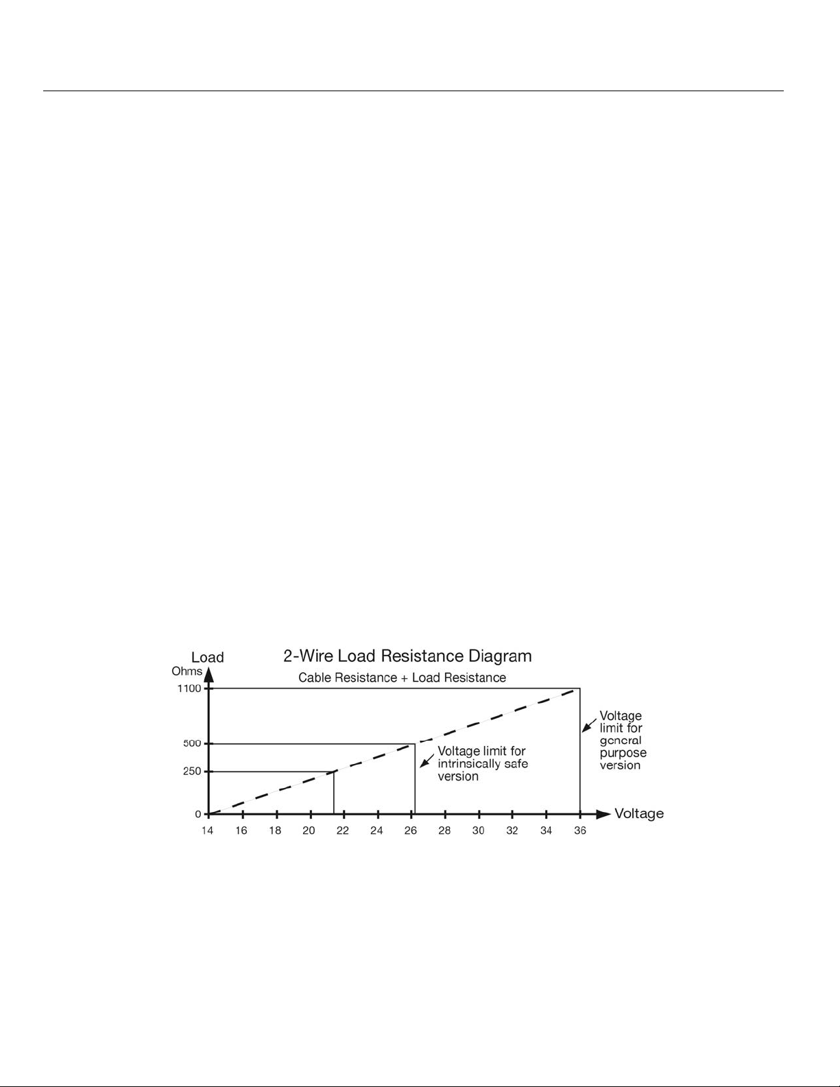
Load Resistance: See chart below
2
/s, 10 -150 Hz
| 8 MN301900 Rev B
Page 9
Introduction / Table of Contents (continued) Step One
Power:
Power Supply: 24 VDC (21.6 to 26.4 VDC) the same two-wire connection cable carries power
supply and current signal.
Power Consumption: 22.5mA maximum
Ripple Allowed:
<100Hz: <1V
100 to 100 KHz: <10mV
Enclosure Rating: LR11, LR16, LR21, LR26: ........................... IP67 (NEMA 6)
LR31: ........................................................... IP68 (NEMA 6P)
Cable Connection: Standard 2-wire shielded cable with earth ground wire and outside diameter of 5-
9mm is recommended.
Cable Length (LR31 only): 10m (32.8’) standard /
15m (49.2’) maximum length between LR31 and LR98
Cable Entry/Plug: LR11, LR16, LR21, LR26: ..... One cable entry (½” NPT with adapter, M20x1.5)
LR31: ..................................... One cable entry (1” NPT)
Accuracy Charts
MN301900 Rev B 9 |
Page 10
Introduction / Table of Contents (continued) Step One
Accuracy Charts
| 10 MN301900 Rev B
Page 11
Introduction / Table of Contents (continued) Step One
Communication: FCC (US)
Part 15.209, Class A: LR11, LR16 (2” horn) and LR26 series can only be installed
on metal or reinforced concrete tanks.
Part 15.256, Class B: LR16 (3” & 4” horn), LR21 & LR31 series can be installed
on any tank material.
Compliance: The equipment complies with the following standards:
IEC: 60079-0:2011 & 60079-11:2011
EN: 60079-0:2012 & 60079-11:2012
RoHS
This product is an intrinsically safe version (Ex ia IIC T6…T3 Ga) with stainless steel
housing. All electric circuits are fully encapsulated in the internal enclosure, where no
conductive parts will contact with flammable gas. Two-Wire system in service, the power
of the product is from safety barrier limited at:
U
= 26.4V Ii = 114mA Pi = 0.752W Ci = 0 Li = 51µH
i
A safety barrier should be placed between power source and instrument for intrinsically
safe version. All connection cables must be screened with maximum length of 500m
(stray capacitor ≤ 0.1 µF/Km and stray inductance ≤ 1mH/Km). The level measurement
instrument must be connected to ground potential and unapproved supplemental devices
are not allowed to use.
Application conditions:
Maximum process temperature
Temp. class T6 T5 T4 T3
Ta (max.)
60 °C 60°C 95°C 130°C 180°C
65 °C ----- 70°C 130°C 180°C
70 °C ----- 70°C 130°C 180°C
85 °C ----- ----- 130°C 180°C
Pressure for electronic housing 11.5 psi (80kPa) to 16.0 (110kPa).
Ambient temperature: T6: -20°C ≤ Ta ≤ 60°C
T5: -20°C ≤ Ta ≤ 70°C
T4: -20°C ≤ Ta ≤ 85°C
T3: -20°C ≤ Ta ≤ 85°C
Cable Connection:
This product shall be used with certified IECEx and ATEX cable glands and block plugs. The cable
used for “ia” terminal shall be in compliance with the requirement of EN/IEC 60071-14 clause.
Additional requirements for types of protection “I” – intrinsic safety. It’s installing and operation
instructions should be observed if other cable glands are used.
Care should be taken with the cable glands which should be matched to the cable used outside
diameter property; see mark of cable gland for the outer diameter of being cable used.
In order to ensure the required minimum degree of protection, the bolts of cable glands, blanking plug
and relevant sealing bolts are to be tighten down.
MN301900 Rev B 11 |
Page 12
Introduction / Table of Contents (continued) Step One
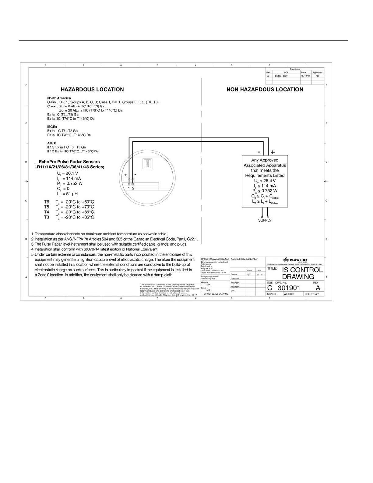
INTRINSICALLY SAFE CONTROL DRAWING 301901
Intrinsically Safe Approvals:
Intrinsic Safe:
North America: Class I, Div.1, Groups A, B, C, D; Class II, Div.1, Groups E, F, G; (T6…T3)
(
Zone 20 AEx ia IIIC (T76°C to T146°C) Da
Ex ia IIC (T6…T3) Ga
Ex ia IIIC (T76°C to T146°C) Da
ATEX: II 1G Ex ia II C T6…T3 Ga;
(TUV) II 1D Ex ia IIIC T76°C…T146°C
IECEx: Ex ia II C T6…T3 Ga;
(TUV) Ex ia III C T76°C…T146°C Da
General: CE, RoHS
Intrinsically Safe Entity Parameters:
U
= 26.4V; Ii = 114 mA; Pi = 0.752W; Ci = 0; Li = 51 μH
i
| 12 MN301900 Rev B
CSAus) Class I, Zone 0 AEx ia IIC (T6…T3) Ga
c
Page 13
Introduction / Table of Contents (continued) Step One
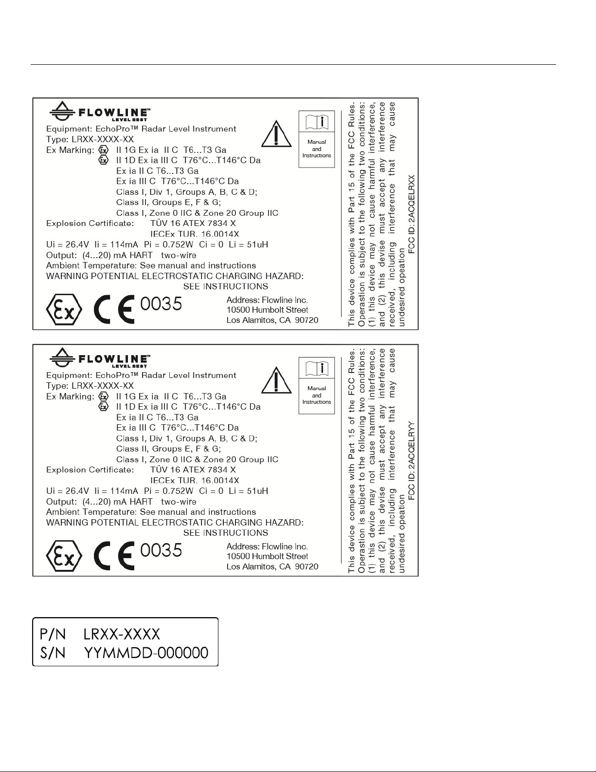
LABELS FOR INTRINSIC SAFETY
Part Number Label
MN301900 Rev B 13 |
Page 14
Introduction / Table of Contents (continued) Step One
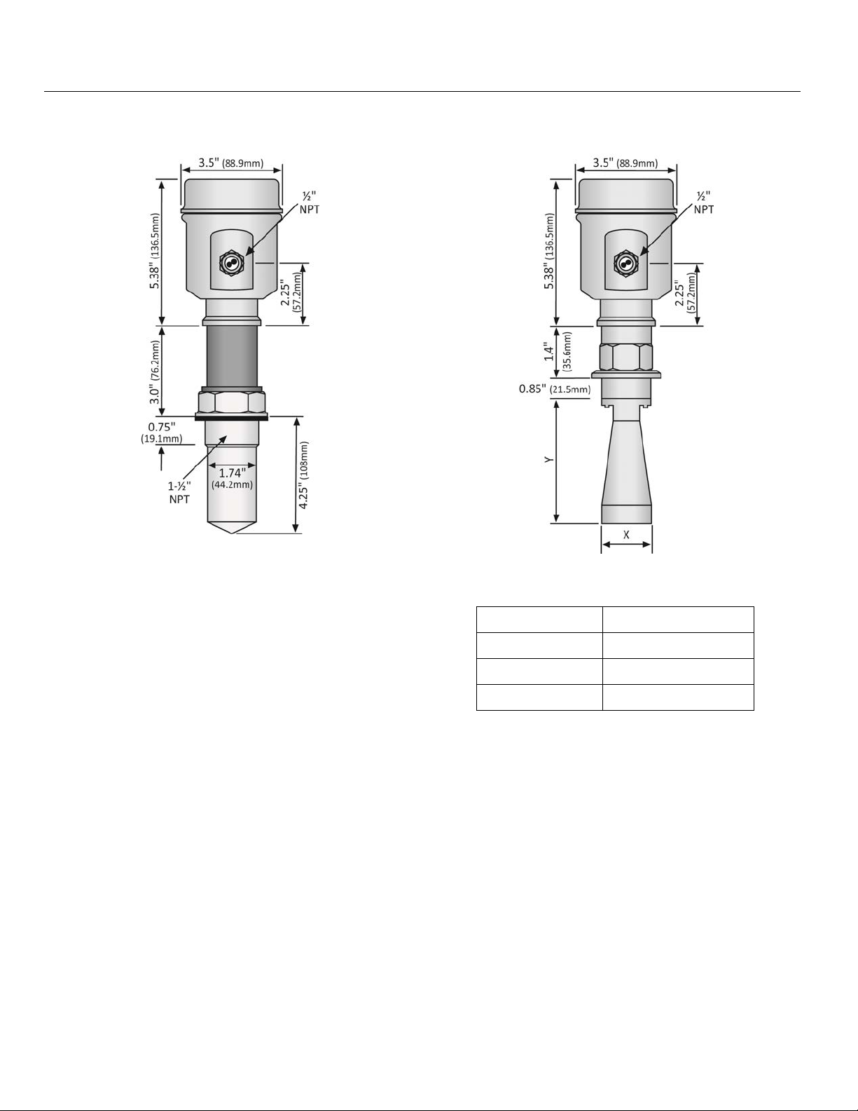
DIMENSIONS
LR11 Series
LR16 Series (Threaded)
LR16 Series (Threaded)
Antenna Dimensions
Diameter (X) Length (Y)
2” (48mm) 5.51” (140mm)
3” (78mm) 8.94” (227mm)
4” (98mm) 11.34” (288mm)
| 14 MN301900 Rev B
Page 15
Introduction / Table of Contents (continued) Step One
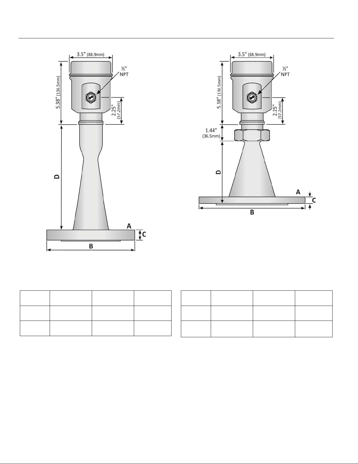
LR21 Series
LR26 Series
LR21 Series Flange / Antenna
Dimensions
Flange
(A)
ANSI
ANSI
3”
4”
Diameter
(B)
7.5”
(190.5mm)
9.0”
(228.6mm)
Thickness
(C)
0.88”
(22.3mm)
0.88”
(22.3mm)
Length
(D)
9”
(228.6mm)
10.5”
(266.7mm)
LR26 Series Flange / Antenna
Dimensions
Flange
(A)
4”
ANSI
6”
ANSI
Diameter
(B)
9.0”
(228.6mm)
11.0”
(279.4mm)
Thickness
(C)
0.57”
(14.5mm)
0.63”
(16.1mm)
Length
(D)
5.71”
(145mm)
9.75”
(247.7mm)
MN301900 Rev B 15 |
Page 16
Introduction / Table of Contents (continued) Step One
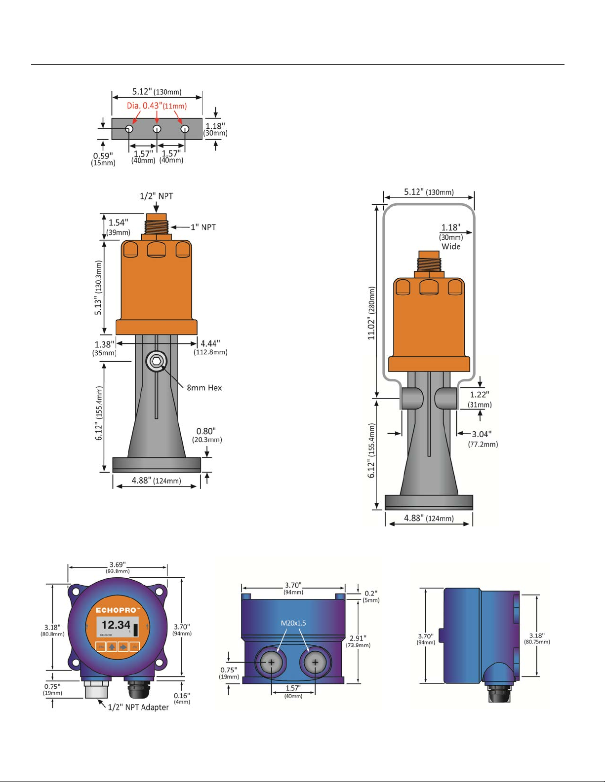
LR31 Series Bracket (Top View)
LR31 Series (Side View A)
LR31 Series (Side View B)
LR98 Series Display
(Front View)
LR98 Series Display
(Bottom View)
LR98 Series Display
(Side View)
Note: Both conduit ports feature M20x1.5 threads. LR98 ships with Liquid Tight Fitting (LM90-1051) and
LR97-S003 Adapter (½” FNPT to M20x1.5). Use the adapter to interface to any ½” MNPT connection.
| 16 MN301900 Rev B
Page 17
Introduction / Table of Contents (continued) Step One
SAFETY PRECAUTIONS
About this Manual: PLEASE READ THE ENTIRE MANUAL PRIOR TO INSTALLING OR USING THIS
®
PRODUCT. This manual includes information on the EchoPro
Radar Level Transmitter from FLOWLINE.
Please refer to the part number located on the sensor label to verify the exact model, which you have
purchased.
User’s Responsibility for Safety: Flowline manufactures a broad range of level sensing technologies.
While each of these sensors is designed to operate in a wide variety of applications, it is the user’s
responsibility to select a sensor model that is appropriate for the application, install it properly, perform tests of
the installed system, and maintain all components. The failure to do so could result in property damage or
serious injury.
Proper Installation and Handling: Only professional staff should install and/or repair this product. Never
over tighten the sensor within the fitting. Always check for leaks prior to system start-up.
Wiring and Electrical: A supply voltage of 16 to 26 VDC is used to power the EchoPro®. Electrical wiring
of the sensor should be performed in accordance with all applicable national, state, and local codes.
Material Compatibility: The enclosure is made of either Aluminum or 316 Stainless Steel (refer to sensor
part number). The antenna is made of Stainless Steel (SS), Polytetrafluoroethylene (PTFE), Perfluoroalkoxy
Alkane (PFA) or Nylon (PA66) with a Viton seal (refer to sensor part number). Make sure that the model, which
you have selected, is chemically compatible with the application media.
Enclosure: The sensor housing is liquid-resistant, but is not designed to be operational when immersed
(LR31 series is designed for submersion but will not provide a true level reading while submersed). Mount the
sensor in such a way that the enclosure and antenna do not come into contact with the application media under
normal operational conditions. The enclosure has a cover that provides access to the push button display
module and terminal strip for wiring. To open the enclosure, you will need to twist the cover counter-clockwise.
Before closing the enclosure, make sure that the enclosure gasket is properly seated, and that any conduit
fittings, cable connectors or plugs are installed correctly and sealed. Note: If using the Flowline LM90-1001
(liquid tight fitting) on the ½” conduit, the cable minimum is 0.170” (4.3mm) and the maximum is 0.450”
(11.4mm).
Make a Fail-Safe System: Design a fail-safe system that accommodates the possibility of sensor and/or
power failure. FLOWLINE recommends the use of redundant back-up systems and alarms in addition to the
primary system.
Flammable, Explosive or Hazardous Applications: EchoPro® is approved for use within intrinsically
safe applications and is intended for use within classified hazardous environments.
Handling Static-Sensitive Circuits and Devices: When handling the instrument, the technician should
follow the below guidelines to reduce the possibility of an electrostatic charge build-up on the technician’s body
from being transferred to the electronic part. Always touch a known good ground source before handling a part.
This should be repeated while handling the part and more frequently after sitting down from a standing position,
sliding across the seat or walking a distance. Avoid touching electrical terminals of the part unless making
connections. DO NOT open the unit cover until it is time to work on the part.
MN301900 Rev B 17 |
Page 18

Getting Started Step Two
SETUP OVERVIEW
The below highlights the initial steps in setting up your sensor for operation.
1. Part Number (Section Two)
1. Prior to purchasing the sensor, you may have submitted a Level Application Questionnaire
(www.flowline.com/LAQ), which based upon the information provided, may have resulted in a
suggested part number. Where so, confirm that the suggested part number matches the part
number of the purchased sensor. If any of the above does not match and/or meet your
application requirements, please contact your distributor.
2. Install Sensor (Section Three)
1. Information on the location and mechanical installation of the sensor.
3. Wire Sensor (Section Four)
1. Information on the electrical wiring and power requirements of the sensor.
4. Basic Configuration Using Display (Section Five)
1. Begin by measuring the tank for all key dimensions.
a. Accuracy in measurement will result in accuracy of sensor performance.
2. Set the Units of Measurement for the sensor.
a. Units can be configured in basic engineering units of length: Feet, Meters
3. Set the Sensor Height for the sensor in the tank.
a. This is the 4mA setting for the output.
4. Set the Fill-Height for the sensor in the tank.
a. This is the 20mA setting for the output.
5. Set the Max. Range (Maximum Range or MaxR) for the sensor in the tank.
a. The sensor will ignore any echo signal returns beyond this setting.
6. Set the Dead Band (Minimum Range or MinR) for the sensor in the tank.
a. The sensor will ignore any echo signal returns closer than this setting.
7. Check the Echo Curve
a. This is a quick check to determine if the sensor is reading the correct level.
| 18 MN301900 Rev B
Page 19

Getting Started (continued) Step Two
5. Process Adjustments (Section Six)
1. Information on OPTIONAL adjustments for specific process conditions that may exist in your
application.
a. Fast filling or emptying of liquid.
b. Liquid surface is turbulent or agitated.
c. Foam on the surface of the liquid.
d. Sensor installed in a still well or sight glass.
e. Powder or Dust is present.
f. Low Dielectric material
g. Large Angle of Repose with the material
6. Advanced Adjustments (Section Seven)
1. Reverse 4-20 mA Output
a. Reverses the current output from 4mA @ bottom and 20mA @ top of tank to
bottom and 4mA @ top of the tank.
2. Fail-Safe Setting
a. Allows for the presetting of the current output when a sensor failure occurs.
3. Minimum Current Setting
a. Sets the minimum current output for the sensor.
4. HART
®
Operation Mode
a. Sets the address for HART® output upon activating the multi-drop setting.
5. Create a New False Echo Curve
a. A method to map out false echo signal returns within the tank.
6. Update an Existing False Echo Curve
a. A method to update false echo signal returns for a section of the tank that was not
exposed during the creation of the original False Echo Curve.
7. Troubleshooting (Section Eight)
1. Measurement Status
a. Determines the measurement reliability and general status of the sensor.
2. Peak Values
a. Displays the lowest and highest level height that the sensor has measured in distance
(d).
3. Simulation
a. Simulates and helps to determine the accuracy and linearity of the sensor.
4. First Echo Adjustment
a. Increases or decreases the strength of the first echo signal return.
5. Echo Curve Zoom In
a. A method to zoom in and view the Echo Curve over a specific range.
6. False Echo Curve Delete
a. A method to delete a previously saved False Echo Curve from memory.
7. Reset
a. A method to reset the sensor’s configuration to the original factory setting.
20mA @
MN301900 Rev B 19 |
Page 20
Get
t
T
w
b
b
RSer
p
w
c
t
h
m
o
L
b
r
a
e
o
e
y
t
g
e
r
n
t
o
t
s
o
n
½
ATEX
u
4
e
ATEX
t
A23
4
b
e
a
w
o
X
H
h
m
m
m
S
e
h
p
o
e
p
e
m
Q
g
r
o
e
r
r
e
PAR
ing Star
NUMBER
ed (cont
inued)
Step Two
Prior
(ww
num
num
L
The
belo
appli
to purc
.flowline.co
er. Where
er can be f
11
ies
art number
part num
ation requi
asing the
/LAQ). B
so, confirm
und on the
R16
S
eries
will indicat
er descripti
ements, pl
LR11
sensor,
sed upon
that the su
outside lab
LR21
Series
the size an
n for speci
ase contact
- 5
4
Housi
-S
5
P
4
ou may
he informa
gested par
l of the sen
LR26
Series
d type of m
fic informati
your distrib
2
ng Material
tainless Ste
ocess Con
- PFA - 1
Approval
2
-
1
-
Outp
-
1
have su
tion provid
number m
or as sho
LR31
Series
unting fittin
on. If any
utor.
0 0
el Intrinsical
ection
" NPT
/ IECEx /
t
-20 mA
mitted a
d, it may
tches the
n below:
g required f
f the abov
ly Safe
HazLoc
Level Ap
ave result
art number
r installing
does not
lication
d in a su
of the sens
the senso
atch and/
uestionnair
gested pa
or. The pa
.
Refer to th
r meet you
t
t
r
| 20
LR16
-
0
5
Housi
- S
5
Pr
0
2
g Material
ainless Ste
cess Conn
- Thread 1
Approval
2
-
1
-
Outpu
- 4-
1
-
0
l Intrinsicall
ection
½" NPT
/ IECEx /
20 mA
ntenna S
- 2" (48
- 3" (78
- 4" (98
Flange
- Thr
0
0
0
y Safe
azLoc
ape
m) Horn
m) Horn
m) Horn
ize
aded Conn
ection
M
N301900 Rev B
Page 21
Getting Started (continued) Step Two
LR21
-
5 3 2 1
Housing Material
- Stainless Steel Intrinsically Safe
5
Process Connection
- ANSI Flange
3
Approval
2
LR26
-
5 3 2 1
Housing Material
- Stainless Steel Intrinsically Safe
5
Process Connection
- ANSI Flange with PTFE insert
3
Approval
2
LR31
-
0 0 2
Housing Material
-PA66 / Nylon
0
Mount
-Bracket
0
Approval
2
- 0 -
0 0
- ATEX / IECEx / HazLoc
Output
- 4-20 mA
1
Flange Size
- 3" Flange (ANSI / DIN)
3
- 4" Flange (ANSI / DIN)
4
- 0 -
0 0
- ATEX / IECEx / HazLoc
Output
- 4-20 mA
1
Flange Size
- 4" Flange (ANSI / DIN)
4
- 6" Flange (ANSI / DIN)
6
1 -
1 0
-
0 0
- ATEX / IECEx / HazLoc
Output
- 4-20 mA
1
Remote Display / Configuration Tool
-With Remote Display
1 0
/Configuration Tool
MN301900 Rev B 21 |
Page 22

Install Sensor Step Three
INSTALLATION REQUIREMENTS
EchoPro® measures the distance between the sensor and the liquid surface below. Typically, all measurements
from the sensor originate from the bottom of the antenna. Refer to the Measurement Reference Chart to
determine the location where measurement originates on your sensor. To ensure reliable measurement,
adhere to the following minimum installation requirements:
1) There are no obstructions between the bottom edge of the installed antenna and the surface of the liquid below
including ladders, walls, tank seams, liquid inflows, rails, other sensors, mixer blades, heating coils, pumps,
struts or apparatus. Note: Additionally, when the sensor transmits a micr owave pulse, the RF signal spread s in a
conical shape (determined by its beam angle) over distance. Refer to the Beam Angle Chart to determine, what
if any, additional measurement space is required to be free of such obstacles. If such items are present, then a
False Echo Curve configuration must be conducted (Section Seven).
2) The sensor must be installed with the antenna perpendicular to the surface of the media.
3) The sensor must be installed with a distance ≥ 19.7” (500mm) from the side wall of the tank.
4) The media level must not be allowed to enter into the dead band (blanking zone) of the sensor.
5) The sensor installation must be done in accordance with relevant local or federal safety regulations.
6) The sensor must be connected to electrical ground.
7) Do not use the housing to screw the sensor into the installation fitting (LR11 & LR16 Series).
a) Applying force against the housing to tighten may damage the sensor.
8) Make sure that any part of the sensor as exposed to the application, specifically any portion installed within
the tank, are suitable for the process.
a) Consider any effects from the application temperature, pressure or media.
| 22 MN301900 Rev B
Page 23
Install Sensor Step Three
FCC CONFORMITY
This instrument complies with Part 15 of the FCC Rules. Operation is subject to the following two
conditions: (1) this instrument may not cause harmful interference, and; (2) this instrument must accept
any interference received, including interference that may cause undesired operation.
Changes or modifications not expressly approved by the manufacturer could void the user’s authority to
operate the equipment.
Warning: User must maintain a safe zone distance of at least 20cm (7.87”) from the antenna.
Note: LR11, LR16 (2” horn) & LR26 series: This equipment has been tested and found to comply with
the limits for a Class A digital device, pursuant to part 15 of the FCC Rules. These limits are designed to
provide reasonable protection against harmful interference when the equipment is operated in a
commercial environment. This equipment generates, uses, and can radiate radio frequency energy and, if
not installed and used in accordance with the instruction manual, may cause harmful interference to radio
communications. Operation of this equipment in a residential area is likely to cause harmful interference in
which case the user will be required to correct the interference at their own expense.
This equipment is not allowed to be connected to public utility power lines.
NOTE: LR16 (3” & 4” horn), LR21 & LR31 series: This equipment has been tested and found to
comply with the limits for a Class B digital device, pursuant to Part 15 of the FCC Rules. These limits
are designed to provide reasonable protection against harmful interference in a residential installation.
This equipment generates uses and can radiate radio frequency energy and, if not installed and used in
accordance with the instructions, may cause harmful interference to radio communications. However,
there is no guarantee that interference to radio and television reception, which can be determined by
turning the equipment off and on, the user is encouraged to try to correct the interference by one or
more of the following measures:
Reorient or relocate the receiving antenna.
Increase the separation between the equipment and the receiver.
Isolate the equipment to an outlet different from where the receiver is connected.
Consult the dealer or an experienced technician for help.
MN301900 Rev B 23 |
Page 24
Install Sensor (continued) Step Three
LR16 ANTENNA PREPARATION
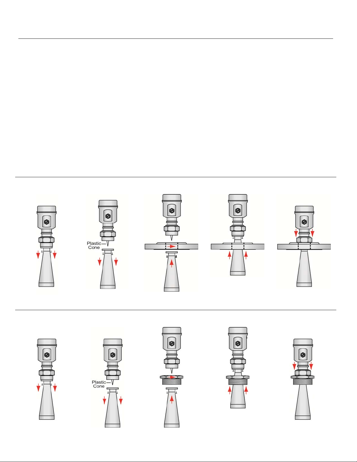
The LR16 Series antenna (only) may be removed from the sensor to allow a flange or reducer bushing
accessory to be attached to the 1 ½” NPT mounting threads and/or, the antenna may be inserted from within
the inside of the tank through the bottom of an existing fitting (where the base of the antenna is too wide to pass
through the fitting from the top). Referencing the illustrations, follow the below steps to disconnect, mount and
reattach the antenna.
1) Loosen and remove the four (4) socket screws using a 3mm Allen wrench.
2) Carefully remove the antenna. Note: Do not remove or damage the plastic cone (microwave RF emitter)
within the antenna socket.
3) Insert the antenna through the bottom of the fitting. Note: If doing so from the inside of the tank, make sure
to secure it, so as to prevent the antenna from falling into the tank.
4) Connect the sensor to the antenna socket and reattach the four (4) screws using a 3mm Allen wrench.
5) Attach the sensor to the fitting as necessary.
Add a Flange
Remove Screws Remove Antenna Insert Antenna Connect Antenna
to Sensor,
Thread Sensor to
Flange
Attach Screws
Add a Reducer Bushing
Remove Screws Remove Antenna Insert Antenna Connect Antenna
to Sensor
Attach Screws
Thread Sensor to
Reducer Bushing
| 24 MN301900 Rev B
Page 25
Install Sensor (continued) Step Three
MOUNTING POSITION
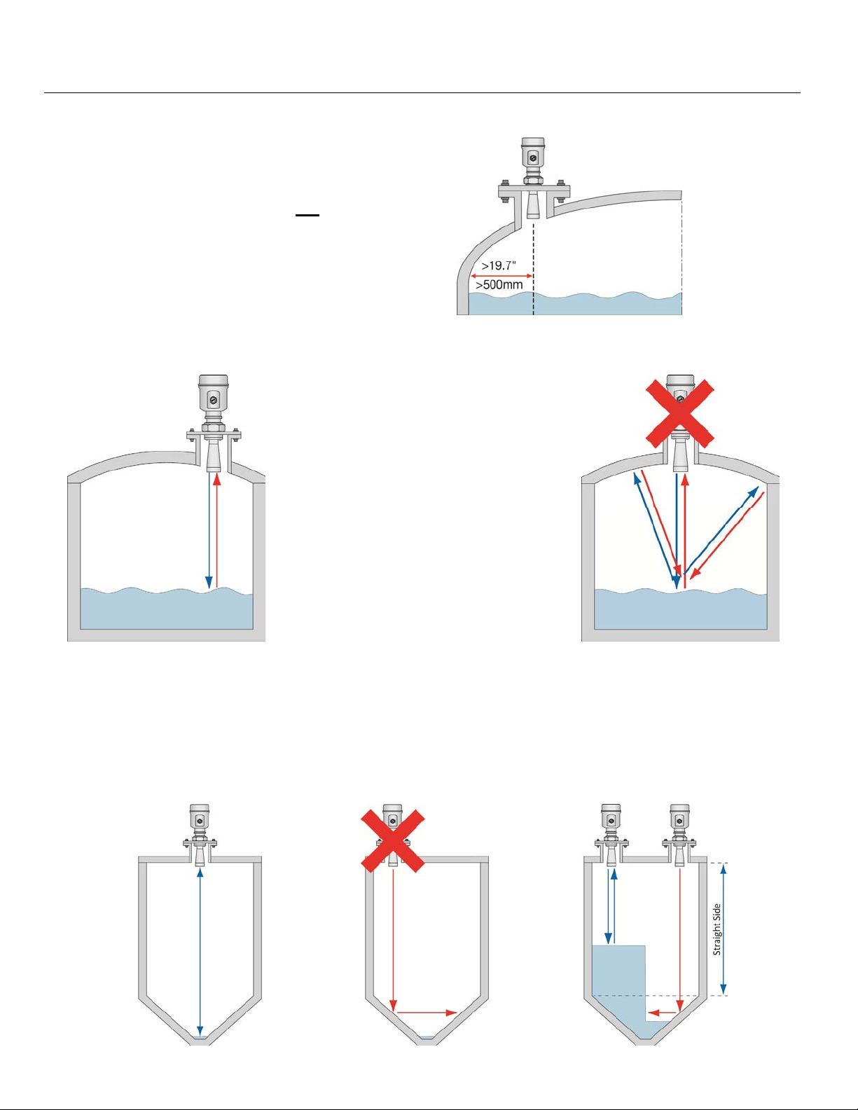
The minimum distance (independent of beam angle) that
the sensor can be mounted next to the straight side wall of
the tank is 19.7” (500mm) as measured from the sensor
centerline to the side wall. If you are not
sensor more than 19.7” (500mm) away from the side wall,
or if there is material build up on the side wall (within the
beam angle), perform a False Echo Curve during initial
configuration.
Avoid mounting the sensor in the center of a dome top tank. The center of such a tank will multiply the echoes,
making sensor operation difficult.
able to install the
Correct Mounting
Sensor mounted off center in a
dome top tank.
Incorrect Mounting
Sensor mounted in the center of a
domed top tank resulting in
multiple echoes.
In cone bottom tanks, it can be advantageous to mount the sensor in the center of the tank, making it possible
for the sensor to measure closer to the bottom of the tank. If the sensor is mounted over an angled bottom, and
the level drops below the angle, the echo will be deflected away from the sensor, resulting in poor operation.
The sensor can be mounted over an angled bottom as long as the level is maintained within the straight side
wall so the sensor will receive echo returns.
Center Mount - Correct Level Below Side Wall -
Incorrect
Level Above Side Wall –
Correct
MN301900 Rev B 25 |
Page 26
Install Sensor (continued) Step Three
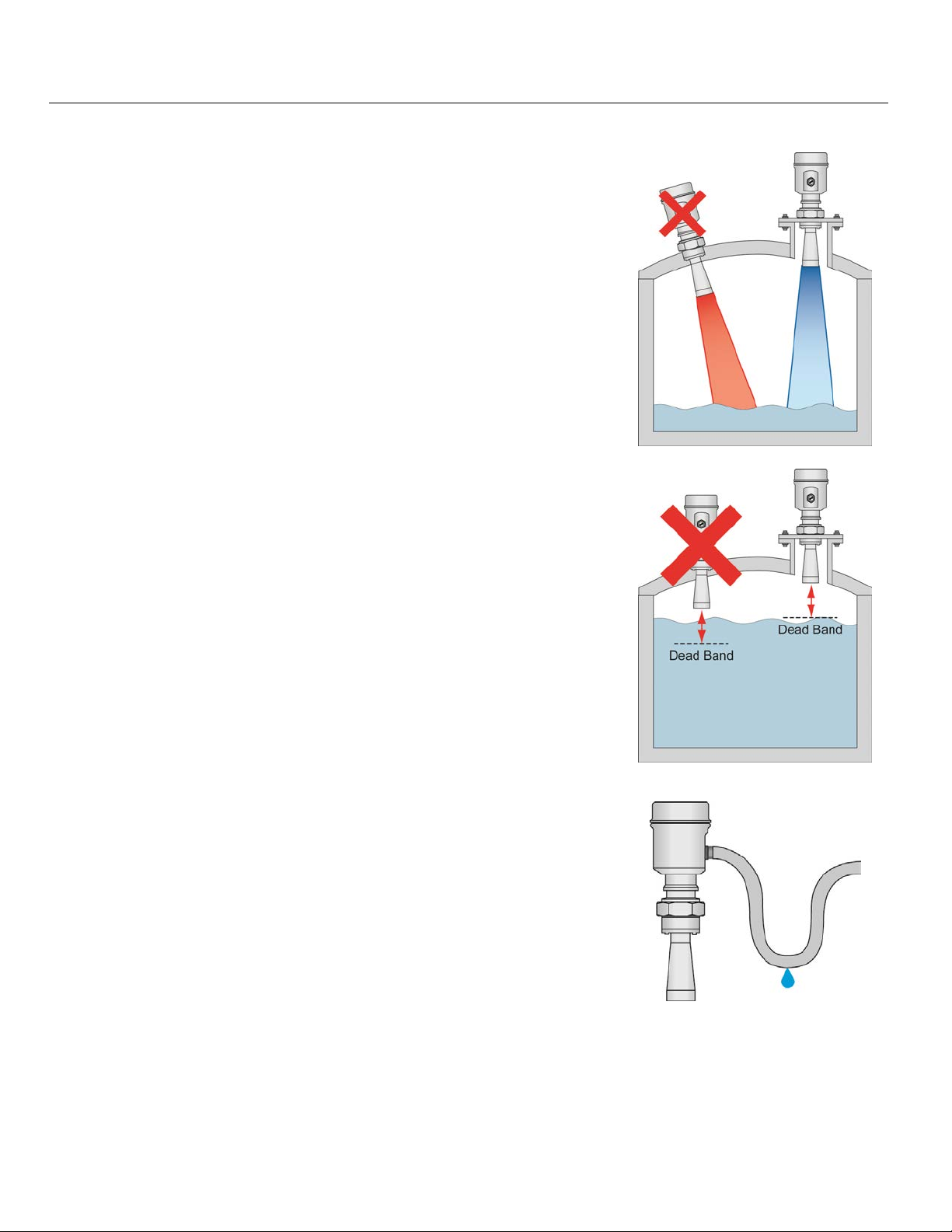
MOUNT THE SENSOR PERPENDICULAR TO THE LIQUID LEVEL
Always mount the sensor perpendicular to the surface of the media. This
will enable the return echoes to reach the sensor. Mounting the sensor
off-axis will result in weak return echoes or no return echoes, depending
on the degree of angle.
CONSIDER THE DEAD BAND
The sensor has a dead band (blanking distance) of 12” (30.48mm) as its
default. The dead band can be lowered to within 2” of the bottom of the
antenna (consult with factory). This is an up close distance where the
sensor is not able to measure the level within this range. Typically, the
measurement location for the sensor is at the bottom of the antenna.
When identifying a location for sensor installation, take into account the
length of the antenna combined with the dead band of the sensor.
AVOID CONDENSATION IN THE CONDUIT
You can give your instrument additional protection against moisture
penetration by leading the conduit connection or cable downward in front
of the cable entry. Condensation in the conduit will therefore not enter
the sensor’s enclosure.
| 26 MN301900 Rev B
Page 27
Install Sensor (continued) Step Three
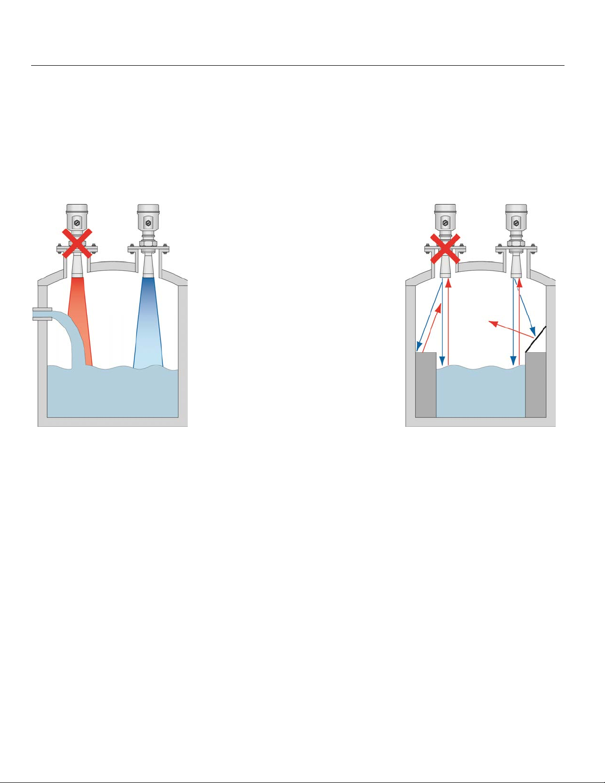
AVOID OBSTRUCTIONS IN THE BEAM PATH
Do not mount the sensor in or above the fill stream, other equipment (ladders, pumps, mixers) or structures
within the beam path of the sensor. Such items can create false echo returns and prevent the actual level from
being identified by the sensor. Find a location where the sensor has a clear view of the media surface. If your
tank has other equipment near or within the beam path of the sensor, a False Echo Curve should be performed
during initial configuration.
Fill Stream Mounting
Mounting on left incorrectly positions
sensor above the tank fill stream inlet.
Mounting on right is correct as the
sensor has an unobstructed view to the
media level below.
Reflector Installation
Mounting on left incorrectly allows the
sensor to receive false echo returns
from the step.
Mounting on right has an angled baffleboard mounted over the step, which
prevents the false echo from returning to
the sensor. As such, the sensor only
receives correct echo returns from the
media level.
MN301900 Rev B 27 |
Page 28
Install Sensor (continued) Step Three
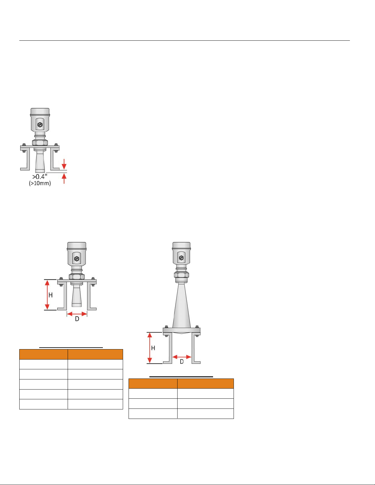
FLANGE RISER INSTALLATION
When installing the sensor on a flange with a riser (or any fitting that is tall and narrow), the antenna must
protrude at least 0.4” (10mm) from the bottom of the riser.
Antenna Extension
LR16 Series Shown
The sensor can be installed within the riser as long as the media has a strong reflective property (dielectric
constant) providing a strong echo return. The below information describes the maximum distance that the
antenna can be recessed within a riser based on the diameter and height of the fitting.
LR16 Series Shown
LR11 & LR16 Series
Diameter (D) Height (H)
1-½” 7.9” (200mm)
2” (50mm) 9.8” (250mm)
3” (80mm) 11.8” (300mm)
4” (100mm) 19.7” (500mm)
6” (150mm) 31.5” (800mm)
LR21 Series Shown
LR21 & LR26 Series
Diameter (D) Height (H)
3” (80mm) 11.8” (300mm)
4” (100mm) 19.7” (500mm)
6” (150mm) 31.5” (800mm)
| 28 MN301900 Rev B
Page 29
Install Sensor (continued) Step Three
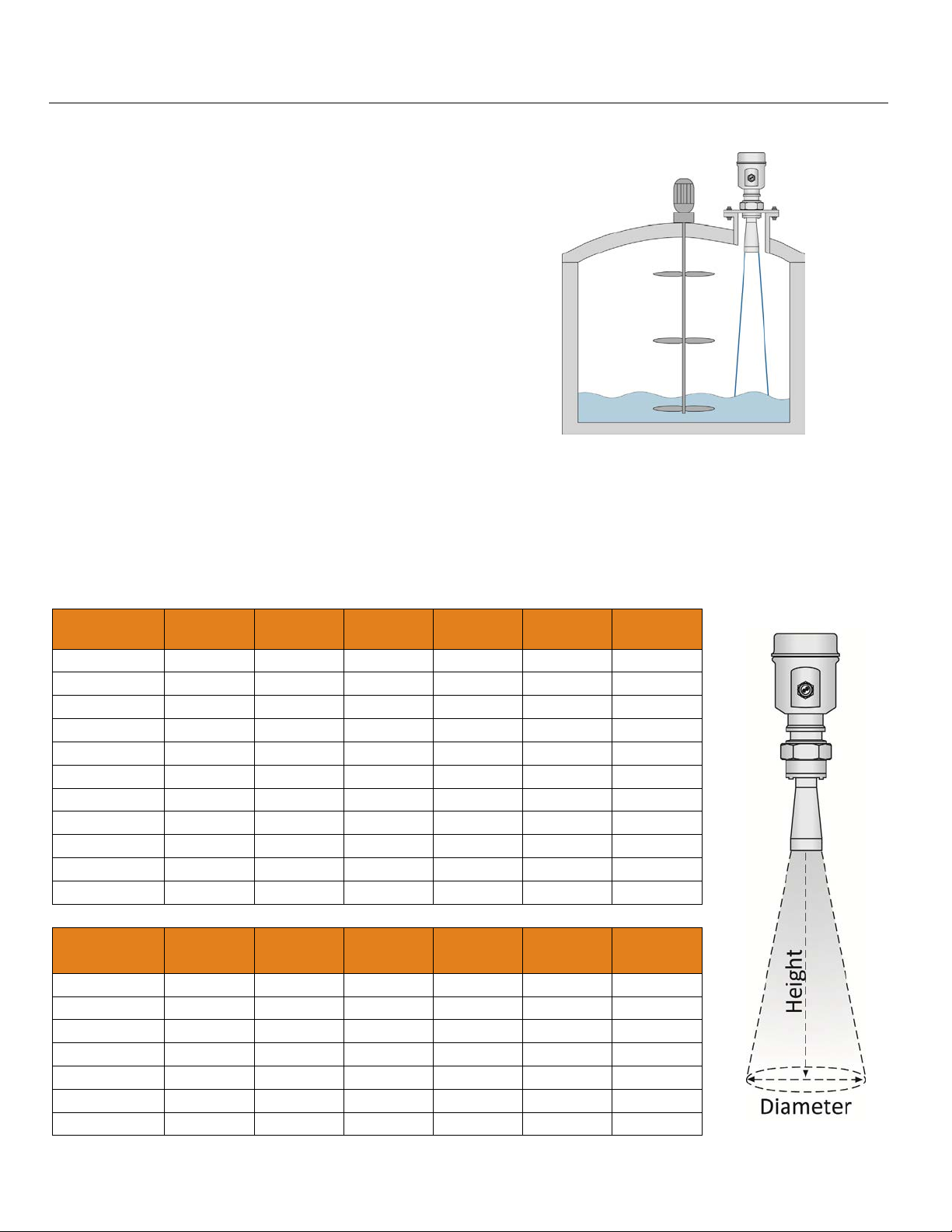
AGITATOR OR MIXER
If there are agitators or mixers in the tank, the sensor
should be mounted as far away from the blades as
possible. Once the installation is complete, a False
Echo Curve should be preformed while the agitator or
mixer is in motion to map out and eliminate false echo
returns from the blades. If significant foam and/or
agitation exist within the application, a stand-pipe
installation should be considered.
BEAM ANGLE
The emitted microwave pulse will expand along its specified beam angle for the entire height of the tank. Place
the sensor so that objects will not interfere with the beam path underneath the sensor. The beam angle is a
function of the sensor Series and antenna length (where variable). Verify the beam angle specification of your
sensor and reference the below charts to determine the amount of free measurement space required under the
installed sensor.
Beam
Angle
8° 12° 18° 20° 22° 24°
LR16
Height Diameter Diameter Diameter Diameter Diameter Diameter
10’
20’
30’
40’
50’
60’
70’
80’
90’
100’
1.40’ 2.10’ 3.17’ 3.53’ 3.89’ 4.25’
2.80’ 4.20’ 6.34’ 7.05’ 7.78’ 8.50’
4.20’ 6.31’ 9.50’ 10.58’ 11.66’ 12.75’
5.59’ 8.41’ 12.67’ 14.11’ 15.55’ 17.00’
6.99’ 10.51’ 15.84’ 17.63’ 19.44’ 21.26’
8.39’ 12.61’ 19.01’ 21.16’ 23.33’ 25.51’
9.79’ 14.71’ 22.17’ 24.69’ 27.21’ 29.76’
11.19’ 16.82’ 25.34’ 28.21’ 31.10’ 34.01’
12.59’ 18.92’ 28.51’ 31.74’ 34.99’ 38.26’
13.99’ 21.02’ 31.68’ 35.27’ 38.88’ 42.51’
Beam
Angle
8° 12° 18° 20° 22° 24°
Height Diameter Diameter Diameter Diameter Diameter Diameter
5m
10m
15m
20m
25m
30m
0.70m 1.05m 1.58m 1.76m 1.94m 2.13m
1.40m 2.10m 3.17m 3.53m 3.89m 4.25m
2.10m 3.15m 4.75m 5.29m 5.83m 6.38m
2.38m 4.20m 6.34m 7.05m 7.78m 8.50m
3.50m 5.26m 7.92m 8.82m 9.72m 10.63m
4.20m 6.31m 9.50m 10.58m 11.66m 12.97m
MN301900 Rev B 29 |
Page 30
Install Sensor (continued) Step Three
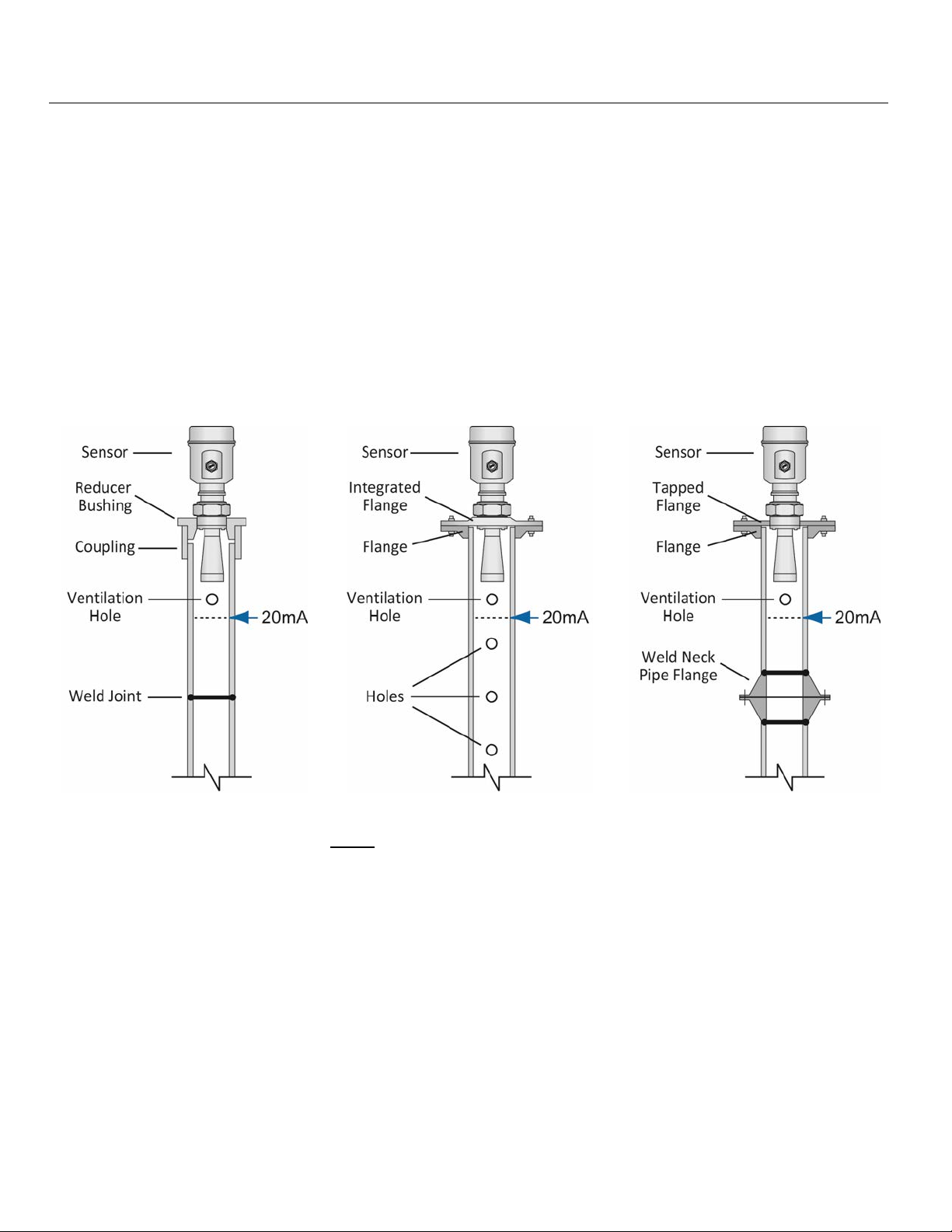
STAND PIPE INSTALLATION
To avoid issues from turbulence, substantial foam or other equipment in the sensors beam path, install the
sensor within a stand pipe (still well). A stand pipe installation can be used with media where the dielectric
constant as low as 1.9. Note: The use of a stand pipe is not recommended with media that significantly coat or
scale. As a rule, if the inside wall of the tank has material build-up, then the inside of the stand pipe will also
have build-up that will affect the sensor’s operation. When installing a sensor in a stand pipe, follow the below
guidelines:
1) The Full Configuration setting (20mA) must be below the upper vent hole and the bottom of the antenna.
2) The Empty Configuration setting (4mA) is typically placed at or near the bottom of the stand pipe.
3) The Stand Pipe function must be activated. It can be found under Medium in the Configuration Menu. The
inner diameter of the stand pipe must be entered within this function.
4) It is recommended to perform a False Echo Curve when the sensor is installed in a stand pipe.
STAND PIPE CONSTRUCTION
1) The stand pipe material must be metal with a smooth inner pipe wall. The minimum pipe size is dependent
upon the Series and antenna length. The LR11 and LR16 sensor can be applied in pipe sizes ≤ 3”
(76.2mm).
2) Any welded joint must be straight with a gap size ≤ 1/254” (0.1 mm).
3) Flanges should be welded to the stand pipe tube.
4) In the case of a pipe extension with a welded neck flange or pipe collar, make sure the inner surfaces are
aligned and accurately joined together.
5) When securing the pipe to the tank, do not weld through the pipe wall.
a) Roughness on the inside caused by unintentional pipe penetration should be removed.
b) Not doing so will cause strong false echo returns and encourage buildup within the pipe.
6) The diameter of any holes along the pipe must be ≤ 1/5” (5 mm).
a) The top ventilation hole must be above the Full Configuration setting (20mA).
b) The holes must be vertically aligned on one side of the pipe with all burrs removed.
7) The number of holes does not matter. The inner diameter of the pipe cannot change over the entire pipe
length.
| 30 MN301900 Rev B
Page 31
Install Sensor (continued) Step Three
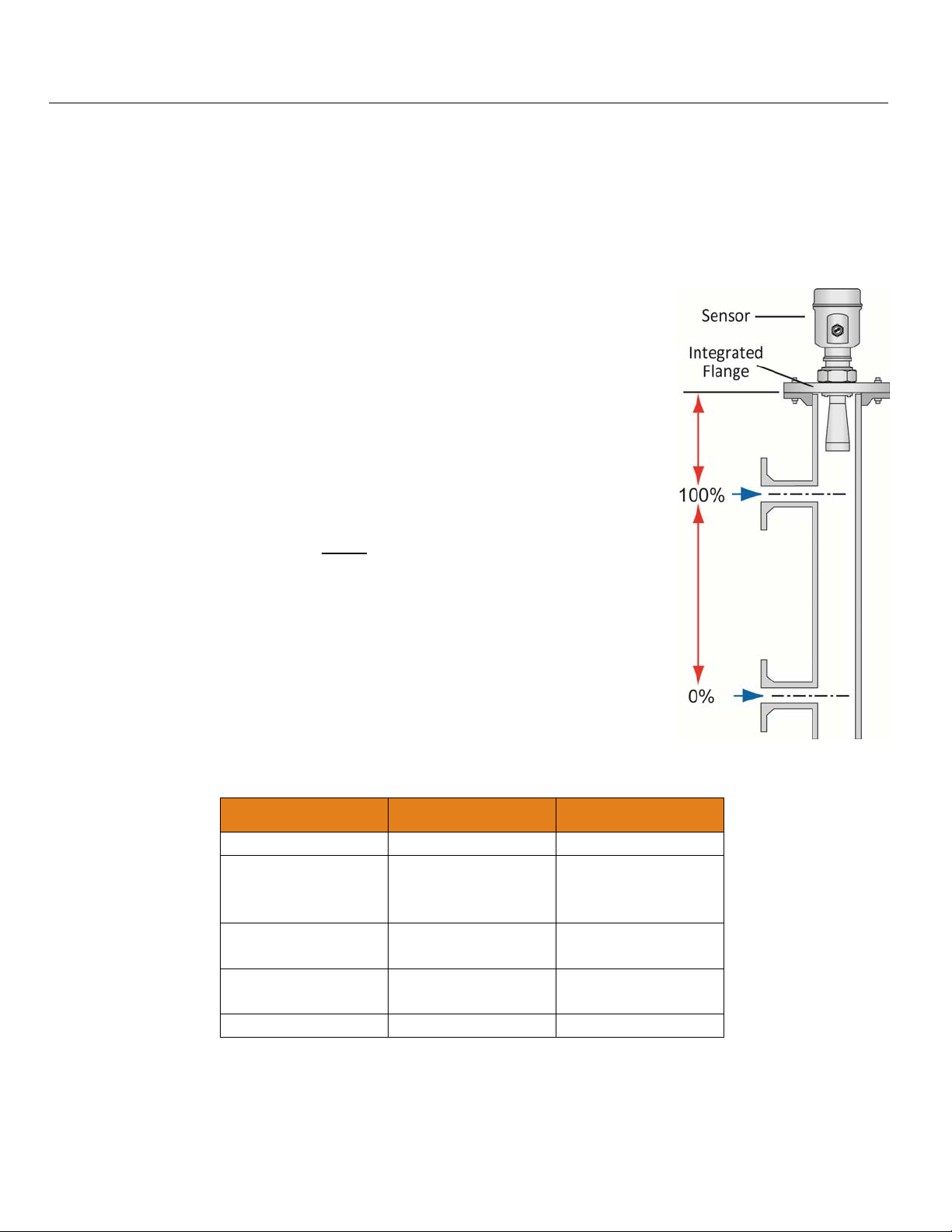
BYPASS INSTALLATION
An alternative to a stand pipe is installing the sensor within a bypass chamber mounted outside of the tank.
Bypass installations can avoid issues from turbulence, substantial foam or other equipment in the sensors beam
path. Note: The use of a bypass is not recommended with media that significantly coats or scales. As a rule, if
the inside wall of the tank has material build-up, then the inside of the bypass chamber will also have build-up
that will affect the sensor’s operation. When installing a sensor in a bypass, follow the below guidelines:
1) The Full Configuration setting (20mA) must be placed at or below the upper
tank connection pipe.
2) The Empty Configuration setting (4mA) must be placed at or above the
bottom tank connection pipe.
3) The Stand Pipe feature must be activated. It can be found under Medium in
the Configuration Menu. The inner diameter of the sight glass must be
entered within this function.
4) It is recommended to perform a False Echo Curve when the sensor is
installed in a sight glass.
BYPASS CONSTRUCTION
1) The bypass material must be metal with a smooth inner pipe wall. The
minimum pipe size is dependent upon the Series and antenna length. The
LR11 and LR16 sensor can be applied in pipe sizes ≤ 3” (76.2mm).
2) There is a minimum distance >11.8” (>300mm) between the bottom of the
antenna and the top edge of the upper tank connection pipe.
3) Any welded joints must be straight with a gap size ≤ 1/254” (0.1 mm).
4) Flanges should be welded to the sight glass tube.
5) The inner diameter of the sight glass cannot change over the entire pipe
length.
STAND PIPE / BYPASS PIPE SIZE VS. SERIES
Series Minimum Pipe Maximum Pipe
LR11: All 2” 3”
LR16: 2” Antenna
3” Antenna
4” Antenna
LR21: 3” Antenna
4” Antenna
LR26: 4” Antenna
6” Antenna
2”
3”
4”
3”
4”
4”
6”
8”
8”
8”
LR31: All N/A N/A
MN301900 Rev B 31 |
Page 32
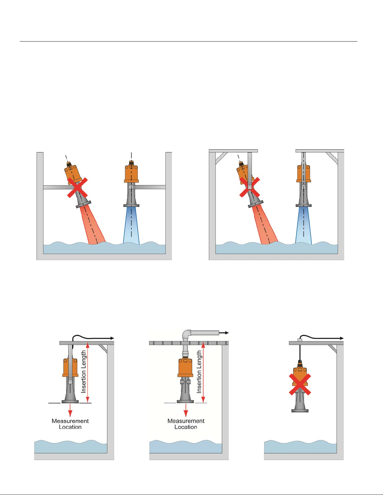
Install Sensor (continued) Step Three
LR31 SENSOR INSTALLATION
The LR31 is unique within the EchoPro® sensor family. It is designed for use in water processing, lift stations,
storm water, sump and environmental storage ponds/reservoirs, streams or dams, which require the sensor to
be installed in locations that are often below grade where flooding is a possibility. The design of the sensor
allows for the unit to be submersed. While the sensor will not be damaged while submersed, the sensor will not
provide correct level readings when submersed. Note: Do not attempt to open the sensor housing. Doing so
will damage the seal, allow moisture into the sensor, and cause a sensor failure. The sensor also features a
submersion resistant 10m (32.8’) cable and IP67 remote push button display module (LR98 described on the
following page) through which the sensor can be configured and the level will be displayed.
Mount the Sensor Perpendicular to the Liquid Level
BRACKET OR CONDUIT MOUNT
Mounting from the bracket or from the 1” conduit connector are both acceptable mounting methods. The
measurement location for all readings is located at the bottom of the sensor. Remember to take into account the
installed insertion length of the sensor when calculating level height within the sump. Note: Never mount the
sensor hanging from the cable. This type of installation will not secure the sensor, may damage the cable
connection and will result in inconsistent level readings as the sensor sways.
| 32 MN301900 Rev B
Page 33
Install Sensor (continued) Step Three
LR98 DISPLAY INSTALLATION
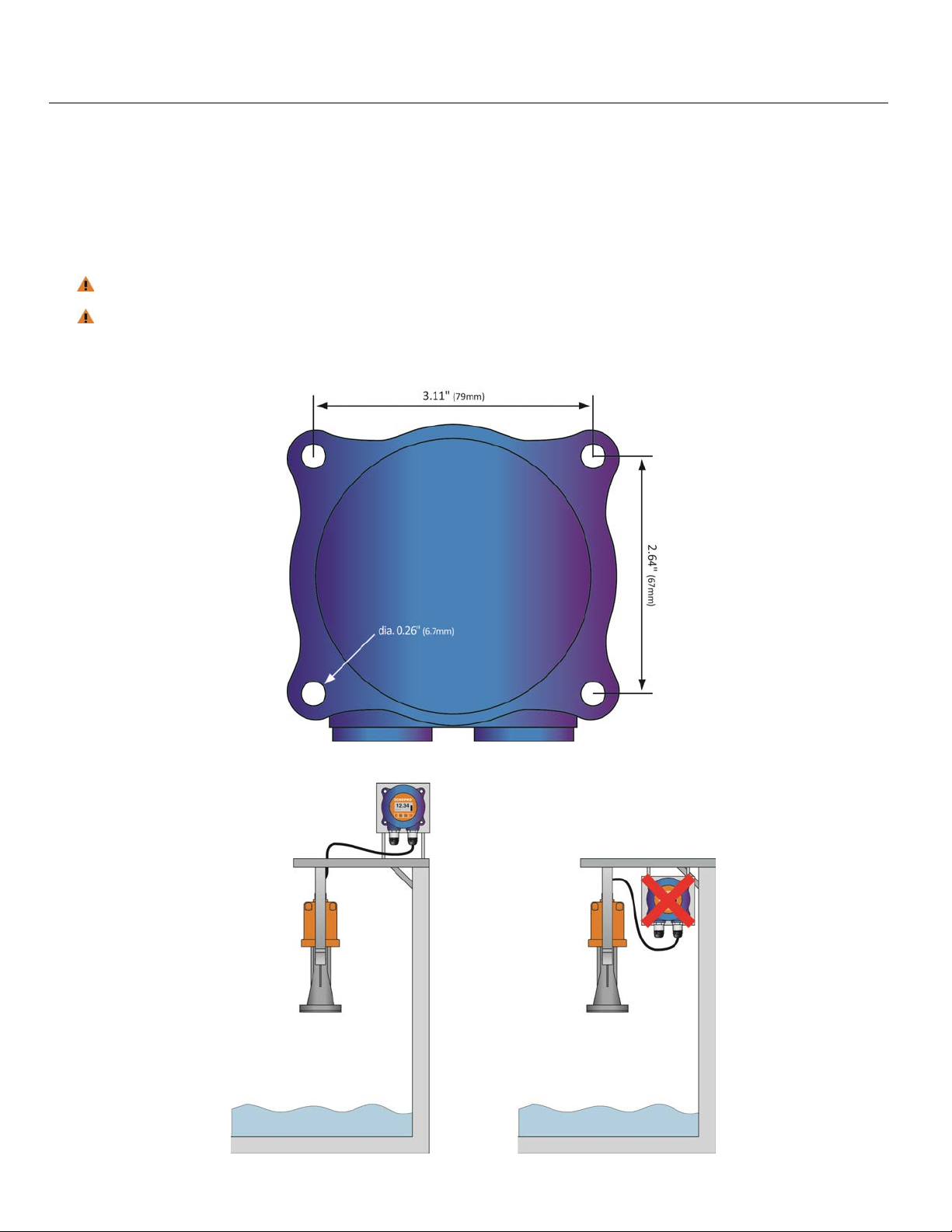
The LR98 is a wall / bulkhead mount IP67 remote push button display module that’s used to configure and
display level readings from the LR31 sensor. The LR98 should be mounted in a location where the display can
be easily read. Note: The LR31 cable length is 32.8’ (10m) which is also the maximum signal distance between
the LR31 and LR98. Take that into account when selecting the LR98 mounting location and use the below drillhole template for installing the display
LR98 display is the HMI for the LR31 and is used only to configure the sensor.
The LR98 is NOT approved for use within intrinsically safe applications and should NOT be used
within classified hazardous environments.
LR98 Rear View
Note: Make sure that the LR98 displa y is m ounted in an abo ve grade locatio n where it will n ot becom e subm ersed.
MN301900 Rev B 33 |
Page 34
Wire Sensor Step Four
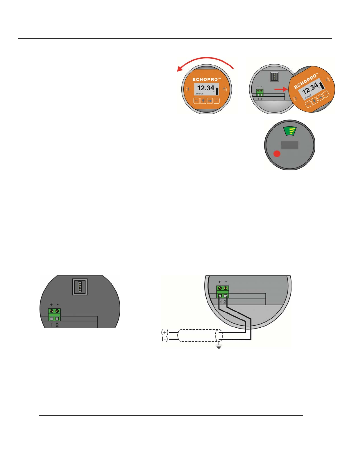
REMOVE THE DISPLAY
To access the terminal strip and conduit ports, you
must remove the display. Gently twist the display
counter-clockwise until you feel the display unlock
from the housing. Next, lift the display from the
housing to view the terminal strip and wire access
ports. Note: This procedure applies to all sensors
including the LR98 remote display for the LR31.
Note: There is an internal configuration difference between displays used by
the EchoPro
®
sensors (LR11, LR16, LR21 & LR26 series) versus the display
used with the LR98 series. A colored dot on the back marks displays to be
used only with the LR98 series. Never swap displays between the LR98
series and other EchoPro
SUPPLY VOLTAGE
®
sensors.
The sensor power supply and current signal share the same two-wire shielded cable. The sensor supply
voltage should never exceed 26.4 VDC. Always provide complete electrical and physical separation between
the sensor supply circuit and the main circuit. Note: Remember that the output voltage of the power supply can
be lower under nominal load (with a sensor current of 20.5 mA or 22 mA) and/or with the addition of other
instruments placed within the circuit. If voltage spikes or surges are expected, adequate isolation protection
must also be provided.
TERMINAL WIRING
The positive (+) and Negative (-) terminals are for connection to a 24 VDC power supply or to a 4-20 mA loop
power source. The wire to the terminals can be extended up to 1,000 feet using 22 gauge or larger wire.
The sensor should be wired with shielded 2-conductor cable (16 to 22 AWG) to protect from electromagnetic
interference. If using a liquid tight connector, select a cable with an outer diameter that is designed to ensure
an effective seal with the connector [typically between 0.20” to 0.35” (5 to 9 mm)].
ELECTRICAL, USAGE AND SAFETY
1. Wiring should always be done by a licensed electrician in accordance with national, state and local codes.
2. Where personal safety or significant property damage can occur due to a spill, the installation must have
a redundant fail-safe backup system installed which accounts for sensor and/or power failure.
| 34 MN301900 Rev B
Page 35
Wire Sensor Step Four
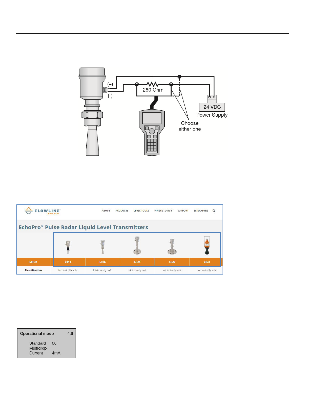
HART® WIRING
If a HART® communicator is used, place a 250 Ohm resistor between the sensor negative (-) and the power
®
supply negative (-). Refer to the wiring diagram below as to the placement of the HART
communicator.
HART® DEVICE DESCRIPTORS (DD FILES)
Note: EchoPro® is HART 7.0 certified and can be configured using a HART communicator. The
Device Descriptor (DD) files have been released on the Flowline website and can be installed onto your
communicator. The files can be found on the individual EchoPro product pages. Simply click on your sensor
from the EchoPro Liquid page (https://www.flowline.com/echopro-liquid-radar/).
STANDARD VS MULTIDROP
HART® enables multiple HART® devices to share the same two wires. If using multiple HART® devises along
the same loop, then each device must have a unique address. Use the Operational Mode (4.6) setting, page
70, to switch from Standard (Address of 00) to Multidrop. Within Multidrop, the address can be changed to a
unique number between 1 and 15. Also, the current consumption of the sensor can be switched from the
default of 4mA to 8mA. When in Multidrop, the sensor will output a constant current reading.
MN301900 Rev B 35 |
Page 36
Wire Sensor (continued) Step Four
g
LR31 CONFIGURATION
There are two main ways to configure the EchoPro® LR31 series:
1) Use a HART
2) Use the included LR98 Display.
If using the HART
configuration easier.
LR31 WIRING AND DESCRIPTION
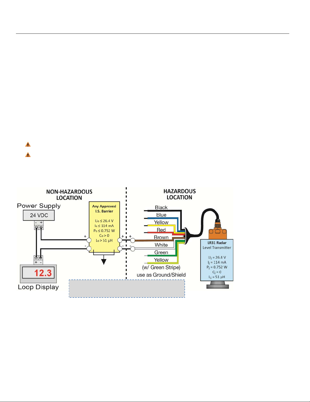
The EchoPro LR31 series has a cable extending from the sensor with 8-wires (see below). The sensor can be
considered a 2-wire loop powered device. The power for the sensor and the 4-20mA output will be a shared
loop using the White (+) and Brown Wire (-). The remaining 6-wires will not be used for normal operation of the
LR31 series.
LR98 display is the HMI for the LR31 and is used only to configure the sensor.
The LR98 is NOT approved for use within intrinsically safe applications and should NOT be used
within classified hazardous environments.
®
communicator.
®
communicator, be sure to download and install the DD files into your communicator to make
The LR31 series is a loop powered device. Use the White wire as the (+) wire and the Brown wire as the (-)
wire. Refer to the following pages for wiring to Displays, Controllers and PLCs.
Note: Always refer to the Control Drawing
301901 for further wirin
information.
| 36 MN301900 Rev B
Page 37
Wire Sensor (continued) Step Four
USING LR98 DISPLAY AS HMI FOR LR31 SERIES
The LR98 display is one of two HMI’s for the LR31 and is used only to configure the sensor.
The LR98 is NOT approved for use within intrinsically safe applications and should NOT be used
within classified hazardous environments.
Use the LR98 to configure the sensor and remove after the sensor has been configured. Configuration can be
performed before installation as long as the dimensions for the installation are known. Accuracy in
measurement will result in accuracy of sensor performance.
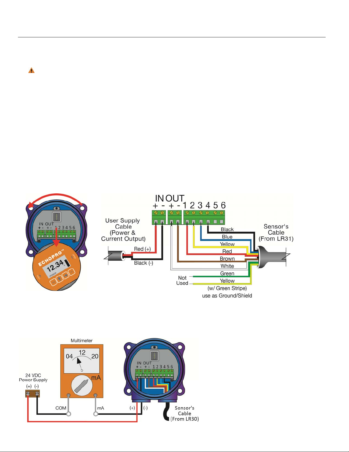
1. Remove the display (as described previously) to access the input and output terminals within the LR98
display.
2. Referencing the below diagram, connect the appropriately colored 6-conductors (of 8 total) from the
LR31 sensor cable to Out [(+) & (-)] & terminals 1-4 on the LR98 display.
3. The remaining 2-conductors (Green and Yellow w/ Stripe) will not be used.
4. Finally, connect the 2-conductors (from the user supplied Cable) for loop power input and current output
to the (+) and (-) terminals on the LR98 display.
5. Replace the display and apply power to the sensor.
LR98 Display Removal LR98 Display Terminals
The attached 8-conductor sensor cable (only 6-wires are used) will wire directly into the display terminals. A
shielded 2-wire cable (user supplied) is required to provide power to and the current output signal from the
display. To confirm the 4-20mA output, place a multimeter (VOM) set to read milliamps in series with the (-)
wire (see below).
MN301900 Rev B 37 |
Page 38
Wire Sensor (continued) Step Four
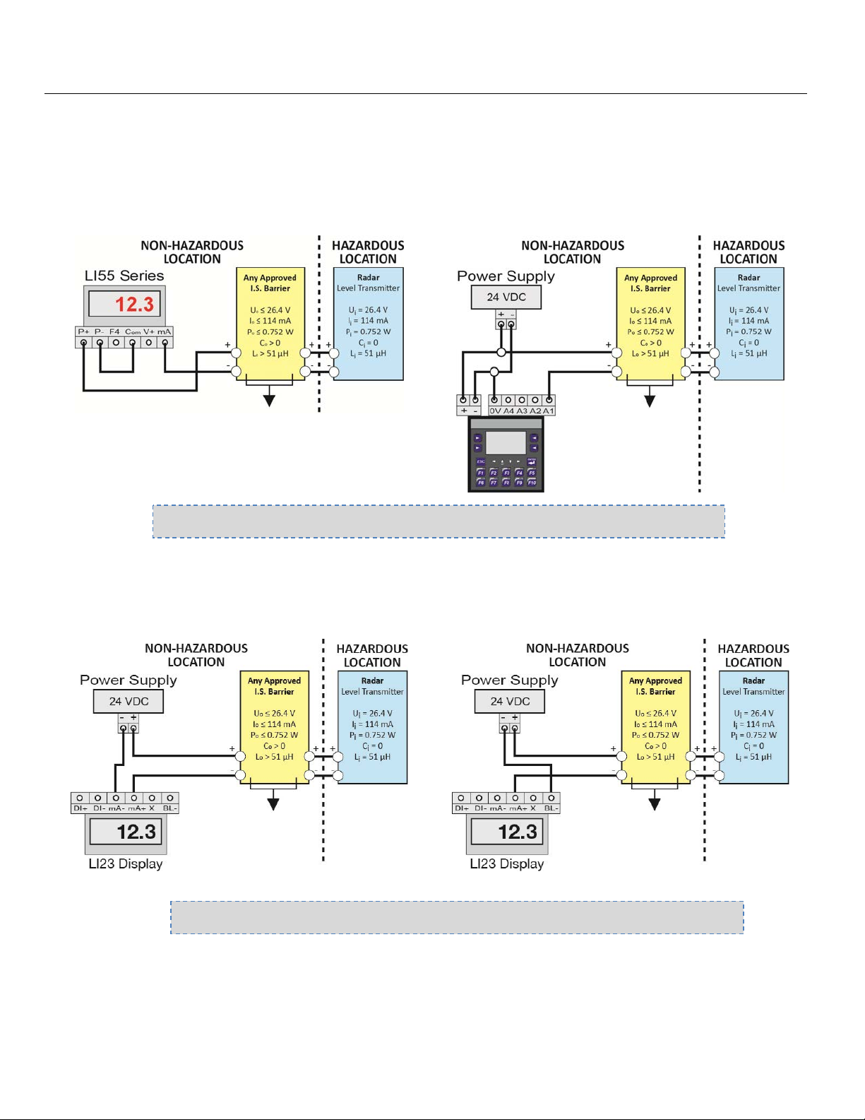
WIRING TO DISPLAYS, CONTROLLERS & PLC’S
Below are examples of how to wire EchoPro® to common displays, controllers and PLC’s.
DataView™ LI55 Series
Level Controller
Commander™ LI90 Series
Multi-Tank Level Controller
Note: Always refer to the Control Drawing 301901 for further wiring information.
DataLoop™ LI23 Series
Level Indicator
(Without Backlight)
DataLoop™ LI23 Series
Level Indicator
(With Backlight)
Note: Always refer to the Control Drawing 301901 for further wiring information.
| 38 MN301900 Rev B
Page 39
Wire Sensor (continued) Step Four
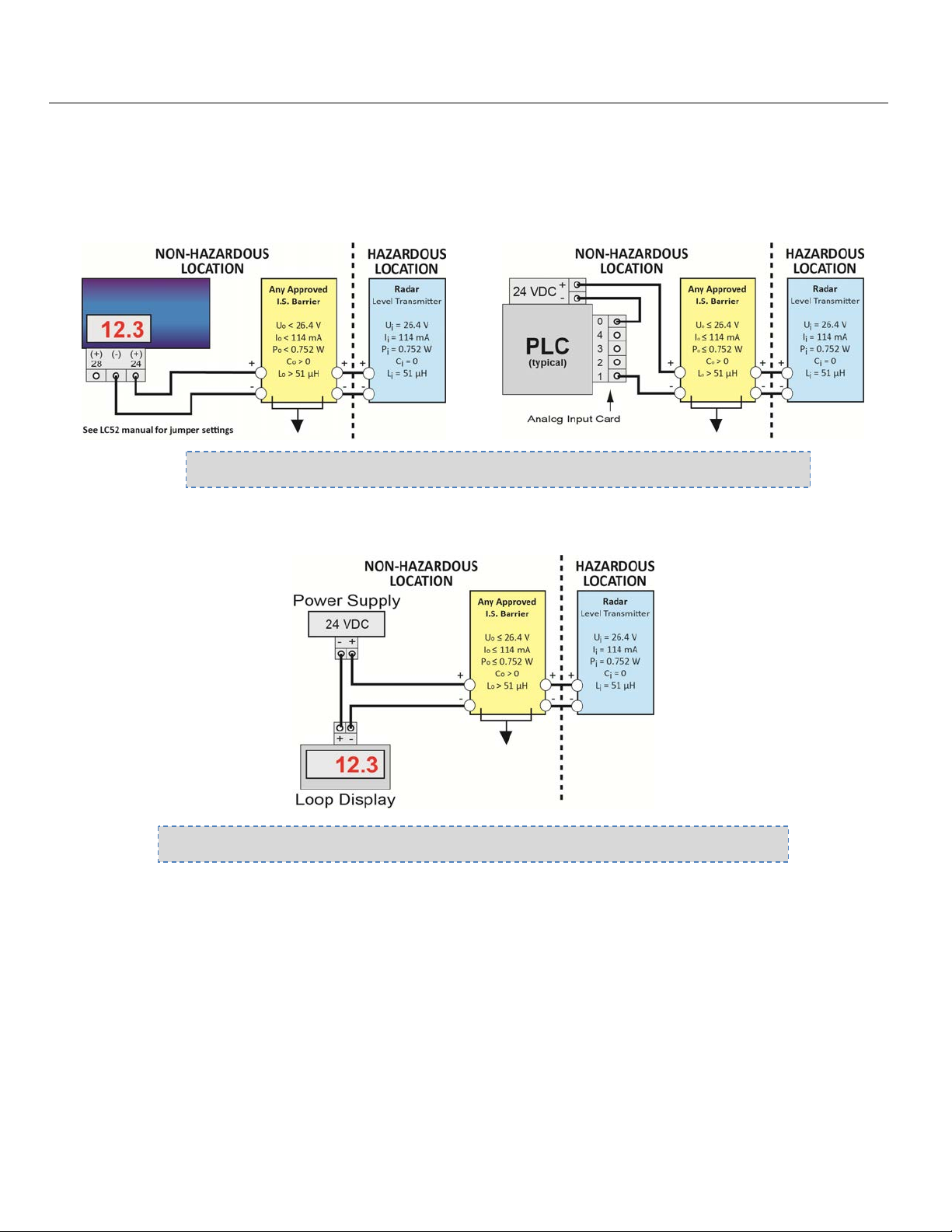
WIRING TO DISPLAYS, CONTROLLERS & PLC’S
DataPoint™ LC52 Series
Generic PLC
Level Controller
(*JWA Mode - Factory Setting)
Note: Always refer to the Control Drawing 301901 for further wiring
Generic Loop Powered Display
Note: Always refer to the Control Drawing 301901 for further wiring information.
* Refer to the DataPoint™ LC52 Series Level Controller manual for information on JWA mode and JWB mode
settings in the controller. Always use the LC52 in JWA mode with the EchoPro
®
.
MN301900 Rev B 39 |
Page 40
Configuration Using Display Step Five
BASIC CONFIGURATION OVERVIEW
Below are the 7 basic steps to configure the sensor for operation. Each step is described in detail on the
following pages
1) Measure the Tank
a) Begin by measuring the key tank and fitting dimensions. Correct tank dimensions will result in accurate
sensor measurement.
2) Set the Units of Measurement
a) Units can be configured in basic engineering units of length including Feet or Meters.
3) Set the Sensor Height
a) This is the empty setting (4mA) for the tank.
4) Set the Fill-Height
a) This is the full setting (20mA) for the tank.
5) Set the Max. Range (Maximum Range or MaxR)
a) This is the maximum measurement range for the sensor. The sensor will ignore all echo returns beyond
this setting.
6) Set the Dead Band (Minimum Range or MinR)
a) This is the minimum measurement range for the sensor. The sensor will ignore all echo returns closer
than this setting.
7) Check the Echo Curve
a) This is a quick diagnostic tool to determine if the sensor is reading the correct level.
Note: When configuring EchoPro®, use
either the Push Buttons in the head of the
sensor or a HART
®
communicator. Either
method will accomplish the goal of sensor
configuration. Changes to the configuration
can be made using the alternative method.
When beginning with one method, it is
recommended to complete the configuration
before using the other method to make an y
adjustments.
| 40 MN301900 Rev B
Page 41
Configuration Using HART Communicator Step Five
BASIC HART COMMUNICATOR OVERVIEW
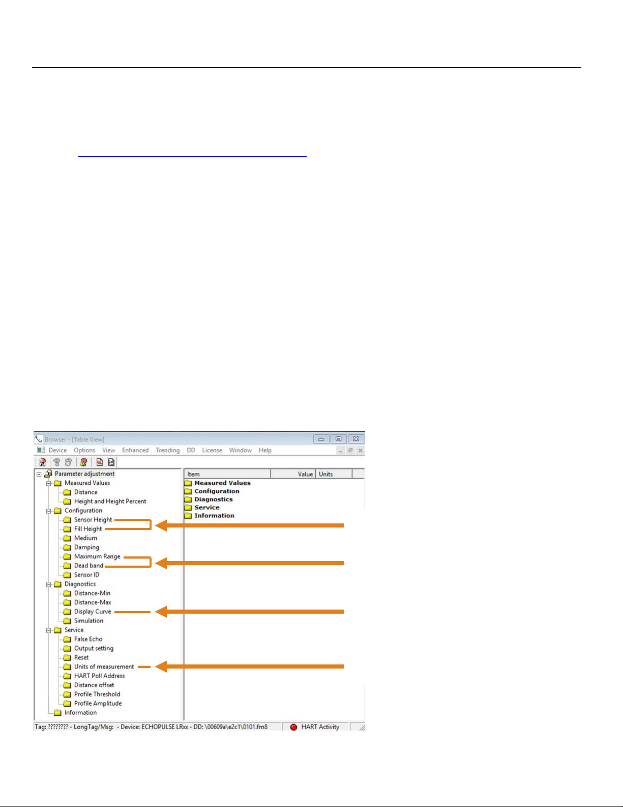
Follow the basic steps outlined on the previous page. Use a HART® communicator or HART® modem with
emulation software. Be sure to download from the Flowline website and load the Device Descriptor (DD) files
onto your communicator or emulation software. The DD files can be found on the individual EchoPro product
pages at https://www.flowline.com/echopro-liquid-radar/. The steps in bold can be used with HART®.
1) Measure the Tank
a) Begin by measuring the key tank and fitting dimensions. Correct tank dimensions will result in accurate
sensor measurement.
2) Set the Units of Measurement
a) Units can be configured in basic engineering units of length including Feet or Meters.
3) Set the Sensor Height
a) This is the empty setting (4mA) for the tank.
4) Set the Fill-Height
a) This is the full setting (20mA) for the tank.
5) Set the Max. Range (Maximum Range or MaxR)
a) This is the maximum measurement range for the sensor. The sensor will ignore all echo returns beyond
this setting.
6) Set the Dead Band (Minimum Range or MinR)
a) This is the minimum measurement range for the sensor. The sensor will ignore all echo returns closer
than this setting.
7) Check the Echo Curve
a) This is a quick diagnostic tool to determine if the sensor is reading the correct level.
3) Sensor Height
4) Fill Height
5) Maximum Range
6) Dead Band
7) Check Echo Curve
2) Units of Measurement
MN301900 Rev B 41 |
Page 42
Configuration Using HART Communicator Step Five
BASIC HART COMMUNICATOR OVERVIEW (CONTINUED)
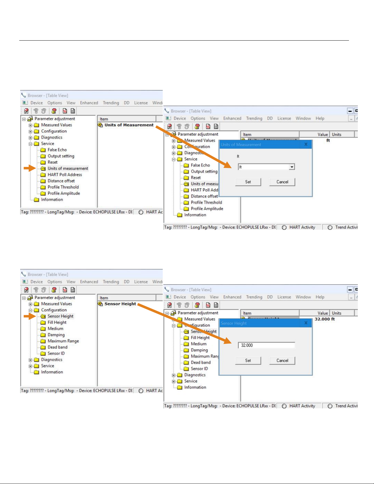
Units of Measurement
To access Units of Measurement, click on the Service folder, then click on the Units of Measurement folder.
Next click on Units of Measurement under Item and use the pull down to change the setting.
Sensor Height
To access Sensor Height, click on the Configuration folder, then click on the Sensor Height folder. Next click on
Sensor Height under Item and use the number field to set the value in the units selected (ft or m).
| 42 MN301900 Rev B
Page 43
Configuration Using HART Communicator Step Five
BASIC HART COMMUNICATOR OVERVIEW (CONTINUED)
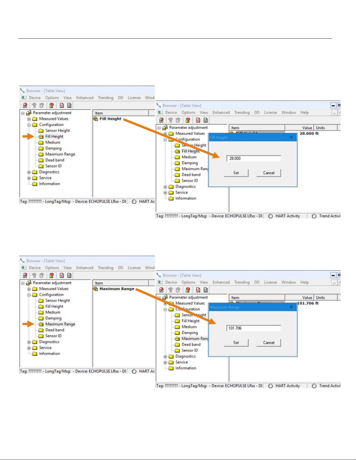
Fill-Height
To access Fill-Height, click on the Configuration folder, then click on the Fill-Height folder. Next click on FillHeight under Item and use the number field to set the value in the units selected (ft or m).
Maximum Range
To access Maximum Range, click on the Configuration folder, then click on the Max. Range folder. Next click
on Max. Range under Item and use the number field to set the value in the units selected (ft or m).
MN301900 Rev B 43 |
Page 44
Configuration Using HART Communicator Step Five
BASIC HART COMMUNICATOR OVERVIEW (CONTINUED)
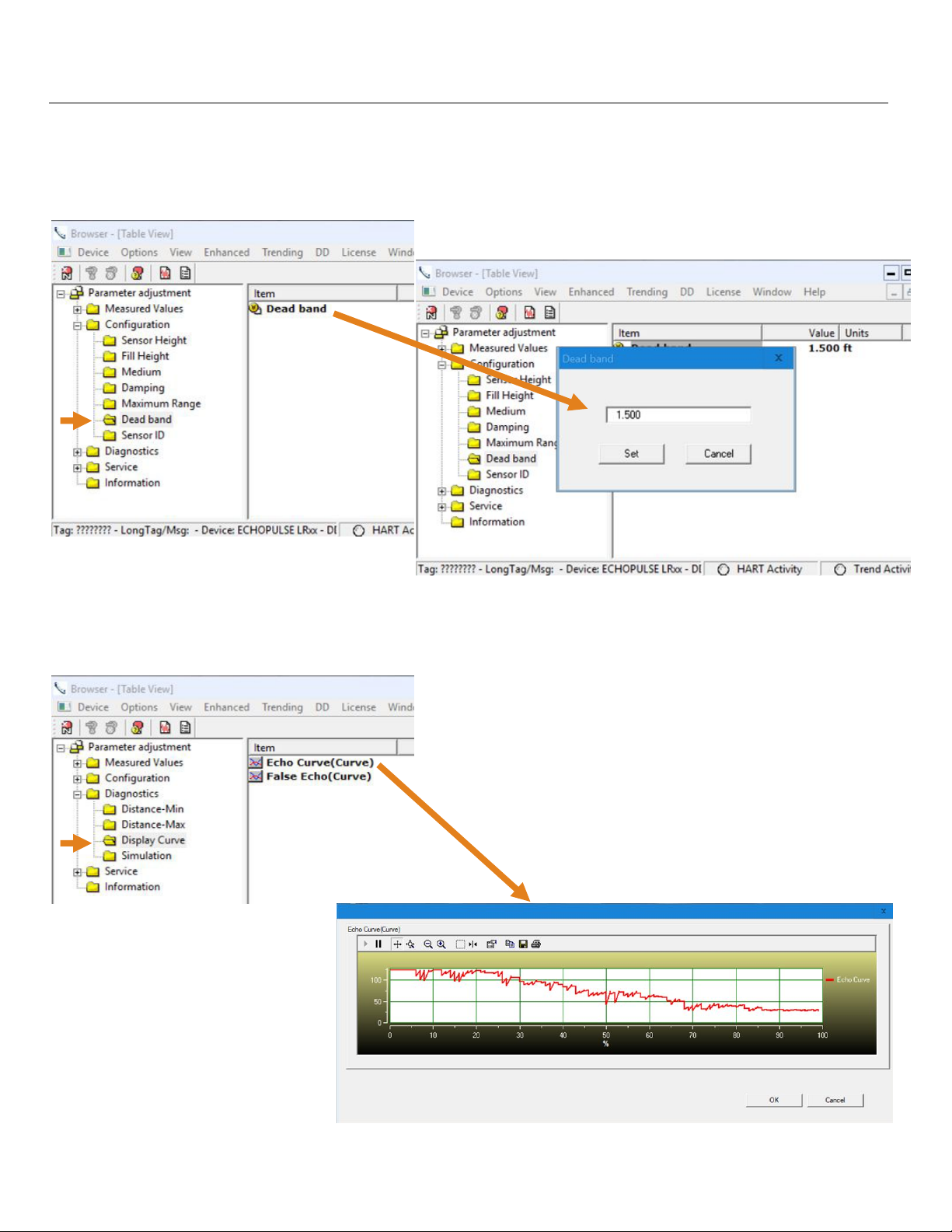
Dead Band
To access Dead Band, click on the Configuration folder, then click on the Dead Band folder. Next click on Dead
Band under Item and use the number field to set the value in the units selected (ft or m).
Check Echo Curve
To access Check Echo Curve, click on the Diagnostics folder, then click on the Display Curve folder. Next click
on EchoCurve (curve) under Item and review the curve for the EchoPro
®
.
| 44 MN301900 Rev B
Page 45
Configuration Using Display (continued) Step Five
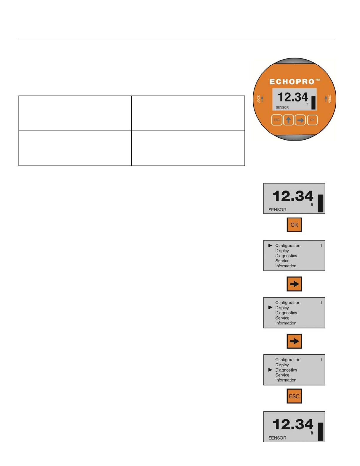
USING THE DISPLAY
The display module features a dot matrix LCD display with 4 push buttons on a
removable puck. Out of the box, the display indicates level in feet and depicts
the level within the 4-20mA span on a bar graph at the right side of the display.
The four buttons perform the following functions:
ESCAPE
o Exit configuration mode
o Return to a higher menu level
Up Arrow
o Modify parameter values
o Choose display mode
o Display Echo Curve
Right Arrow
o Choose configuration options
o Choose parameter digits to edit
o Display contents of parameters
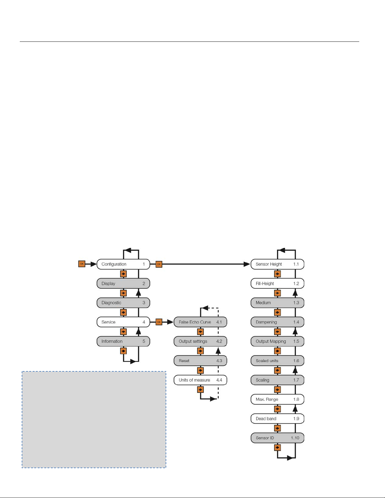
MENU INTRODUCTION
OK
o Enter Menu and Options
o Confirm configuration options
o Confirm changes to parameters
1) To enter the Main Menu (from the Main Screen), press the OK button.
2) Use the Right Arrow button to scroll through the Main Menu options.
a) Configuration - Below are the configuration menu functions:
i) Sensor Height
ii) Fill-Height
iii) Medium
iv) Dampening
v) Output Mapping
vi) Scaled Units
vii) Scaling
viii) Max. Range
ix) Dead Band
x) Sensor ID
b) Display - This menu function sets the display mode and contrast.
c) Diagnostics - Below are the diagnostic menu functions:
i) Measurement of Peak Values
ii) Measurement Status
iii) Echo Curve
iv) Simulation
d) Service - Within the service menu functions, you can store a False
Echo Curve, set units of measurement, change output settings, reset
configuration settings, set language or set a PIN for the sensor.
e) Info - This item provides information on the sensor’s type, serial
number, date of manufacture and software version.
3) To select one of the functions, press OK.
4) To exit the programming mode, press ESC.
MN301900 Rev B 45 |
Page 46
Configuration Using Display (continued) Step Five
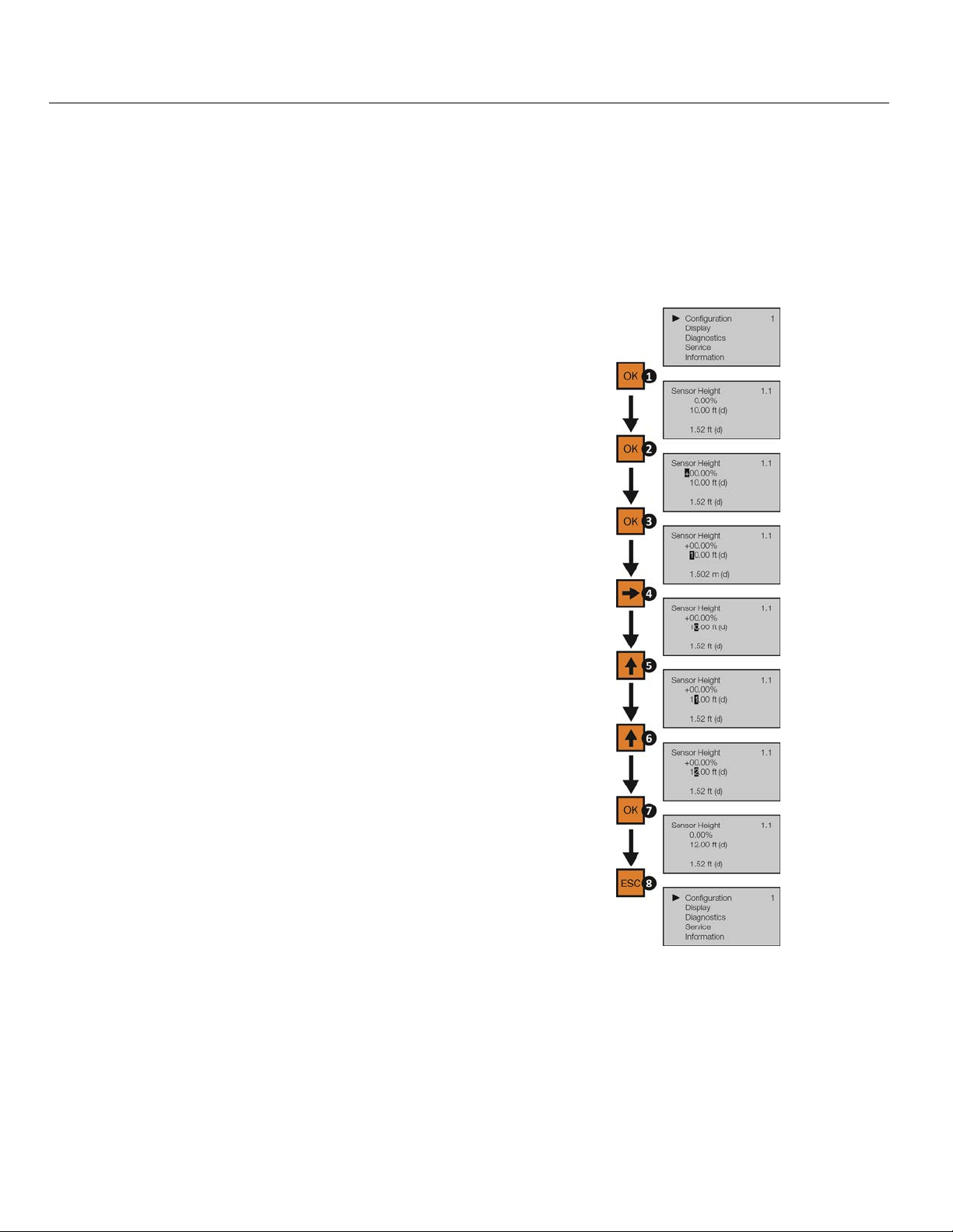
CHANGING DISPLAY VALUES
The numeric values are set using the Right Arrow and Up Arrow buttons. Press the Right Arrow button to
select the next digit and the Up Arrow button to increment the digit value. The digit being changed is
highlighted. Press the OK button to accept a setting or the ESC button to exit without saving changes. The
below exercise illustrates how to change the value of an Empty configuration. Follow the steps to change the
setting from 10.00 ft to 12.00 ft. This example applies to all functional settings starting from the Main Menu.
1) From the Main Menu, press OK to advance into the
Configuration menu.
a) Sensor Height will appear on the top line of the
screen.
2) From Sensor Height, press OK.
a) The “+” sign will be highlighted on the screen.
b) This is the adjustment for the percentage setting.
3) Press OK to move down to the distance setting.
a) The first digit, “1”, will be highlighted.
4) Press Right Arrow to move one digit to the right.
a) Use the Right Arrow button to move the digit
one space to the right.
b) Pressing Right Arrow on the last digit will jump
back to the first digit.
5) Press UP ARROW to increase the digit from “0” to
“1”.
6) Press UP ARROW to increase the digit from “1” to
“2”.
a) Use the UP ARROW button to increase the digit
by one unit.
b) After “9”, the display will jump back to “0”.
7) Press OK to accept the setting as 12.00.
8) Press ESC to move back to the Main Menu.
| 46 MN301900 Rev B
Page 47
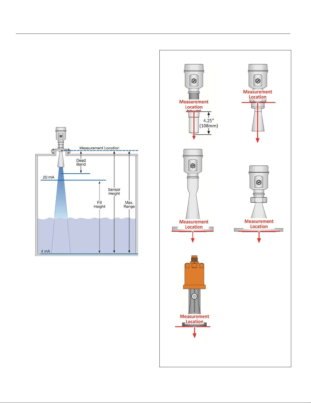
Configuration Using Display (continued) Step Five
STEP 1 - MEASURE THE TANK
Measuring the tank is one of the most important aspects
in configuring the sensor. When measuring the tank,
take into account the location of the sensor with respect
to fittings, risers, dome tops and bottoms, and identify
where the measurements are taken from the sensor.
Note: The location for measurement may be different
among different sensor Series, based upon the type of
antenna. Refer to the Measurement Reference Chart for
the measurement location of your sensor. The basic
measurements for configuration are described below:
Measurement Reference Chart
LR11 Series LR16 Series
LR21 Series LR26 Series
1) Distance from the sensor’s measurement location to
the bottom of the tank is the Max. Range value. The
Range value is typically set at the bottom of the tank.
2) Distance from the sensor’s measurement location to
the empty or lowest liquid level in the tank is the
Sensor Height.
a) Empty Configuration = 4mA setting.
b) With flat bottom tanks, the Max. Range and
Sensor Height values can be the same.
3) Distance from the above 0% location to the full or
highest liquid level in the tank is the Fill-Height.
a) Fill-Height = 20mA setting.
LR31 Series
MN301900 Rev B 47 |
Page 48
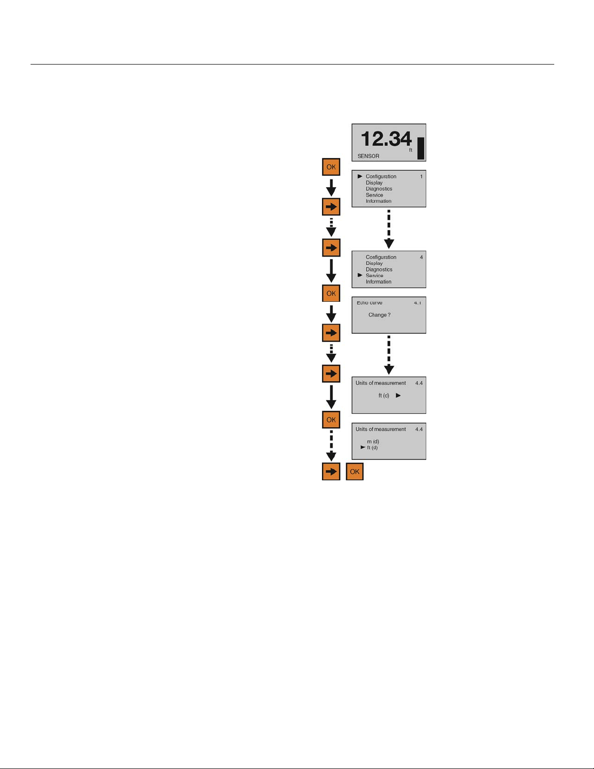
Configuration Using Display (continued) Step Five
STEP 2 - SET THE UNITS OF MEASUREMENT
This function sets the units for all measurement values to be entered into the sensor.
1) From the Main Screen, press OK to advance into
the Main Menu.
2) Press Right Arrow repeatedly until the arrow is
next to Service.
3) Press OK to advance into the Service menu (and
Echo curve will appear).
4) Press Right Arrow repeatedly until the menu
shows Units of Measurement.
5) Press OK to advance into Units of Measurement.
6) Press Right Arrow to change the setting between
feet [ft (d)] and meters [m (d)].
7) When the units are correct, press OK to save the setting.
8) When done, press ESC to return to the Main Menu, and press ESC a second time to return to the Main
Screen.
| 48 MN301900 Rev B
Page 49
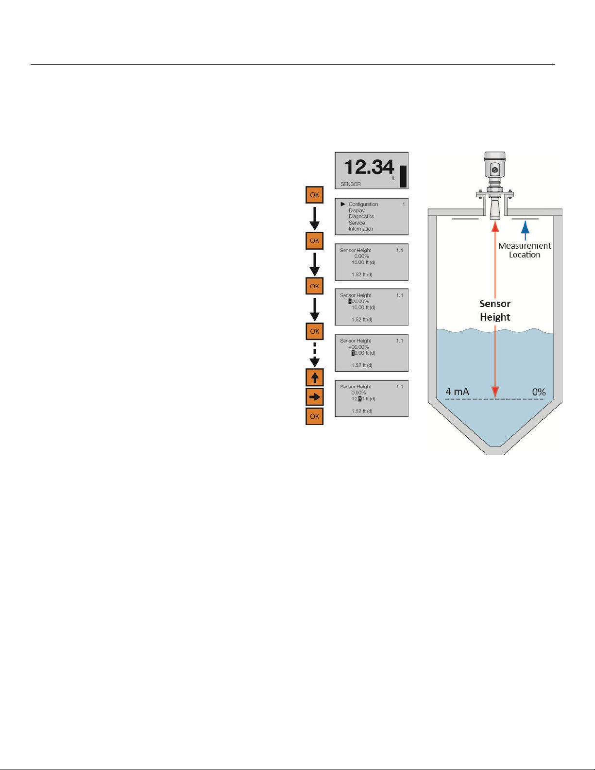
Configuration Using Display (continued) Step Five
STEP 3 - SET THE SENSOR HEIGHT (4MA)
This function sets the Sensor Height point corresponding to an empty position in the tank. The measured
distance of Sensor Height from the sensor will set the 4mA location as well as establish the 0% span of the
sensor.
1) From the Main Screen, press OK to advance into
the Main Menu.
2) Press OK to advance into the Configuration Menu.
3) Press OK to advance into Sensor Height. The first
percentage segment will be highlighted.
4) Press OK again to switch to the distance (d)
setting.
5) Press Right Arrow to move one segment to the
right. Right Arrow will scroll left to right and then
back to the first segment.
6) Press Up Arrow to increase the value of the
number highlighted. Up Arrow will scroll from 0 to
9 and back again.
7) When the value is correct, press OK to save the setting.
8) When done, press ESC to return to the Main Menu, and press ESC a second time to return to the Main
Screen or; if you want to advance directly into Fill-Height, press Right Arrow.
MN301900 Rev B 49 |
Page 50
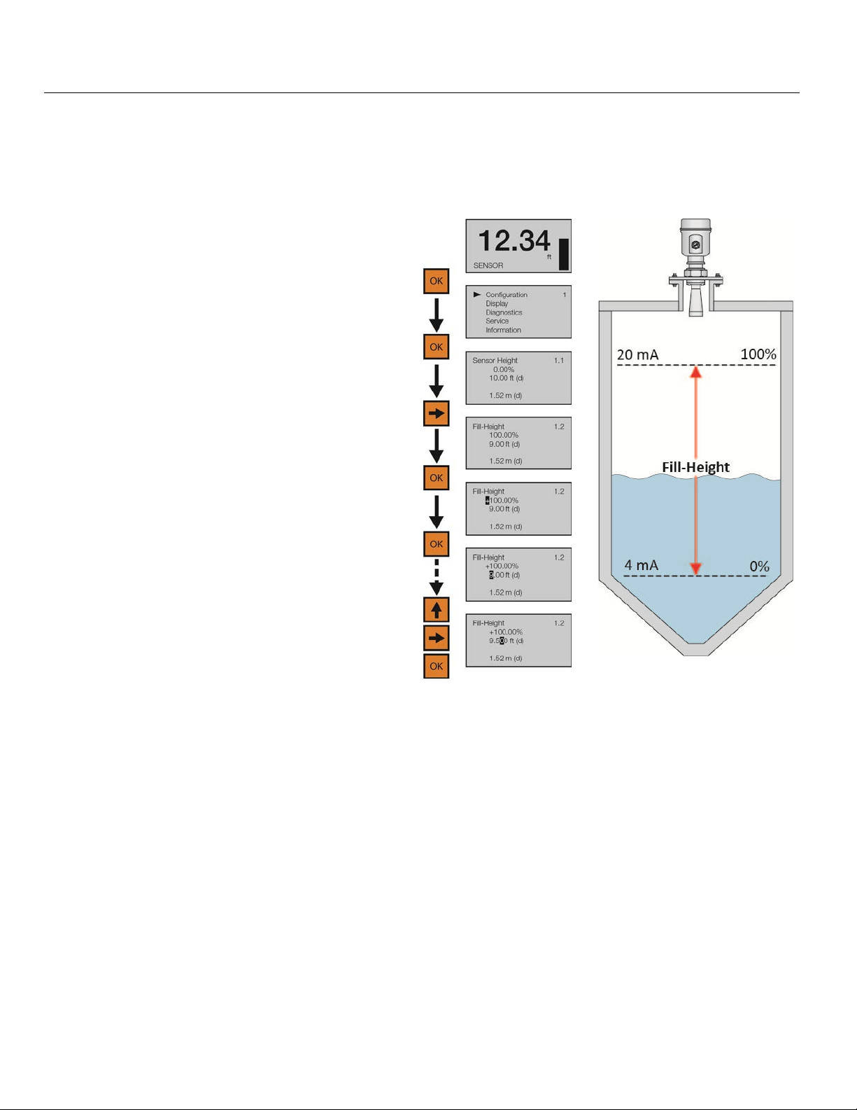
Configuration Using Display (continued) Step Five
STEP 4 - SET THE FILL-HEIGHT (20MA)
This function sets the Fill-Height point corresponding to a full position in the tank. The measured distance of
Fill-Height from the 0% or empty position will set the 20mA location as well as establish the 100% span of the
sensor.
1) From the Main Screen, press OK to advance into
the Main Menu.
2) Press OK to advance into the Configuration
Menu.
3) Press Right Arrow to advance into Full
Configuration.
4) Press OK to advance into Full Configuration.
The first percentage segment will be highlighted.
5) Press OK again to switch to the distance (d)
setting.
6) Press Right Arrow to move one segment to the
right. Right Arrow will scroll left to right and then
back to the first segment.
7) Press Up Arrow to increase the value of the number highlighted. Up Arrow will scroll from 0 to 9 and back
again.
8) When the value is correct, press OK to save the setting.
9) When done, press ESC to return to the Main Menu, and press ESC a second time to return to the Main
Screen or; If you want to advance directly into Range, press Right Arrow repeatedly until Max. Range
appears.
| 50 MN301900 Rev B
Page 51
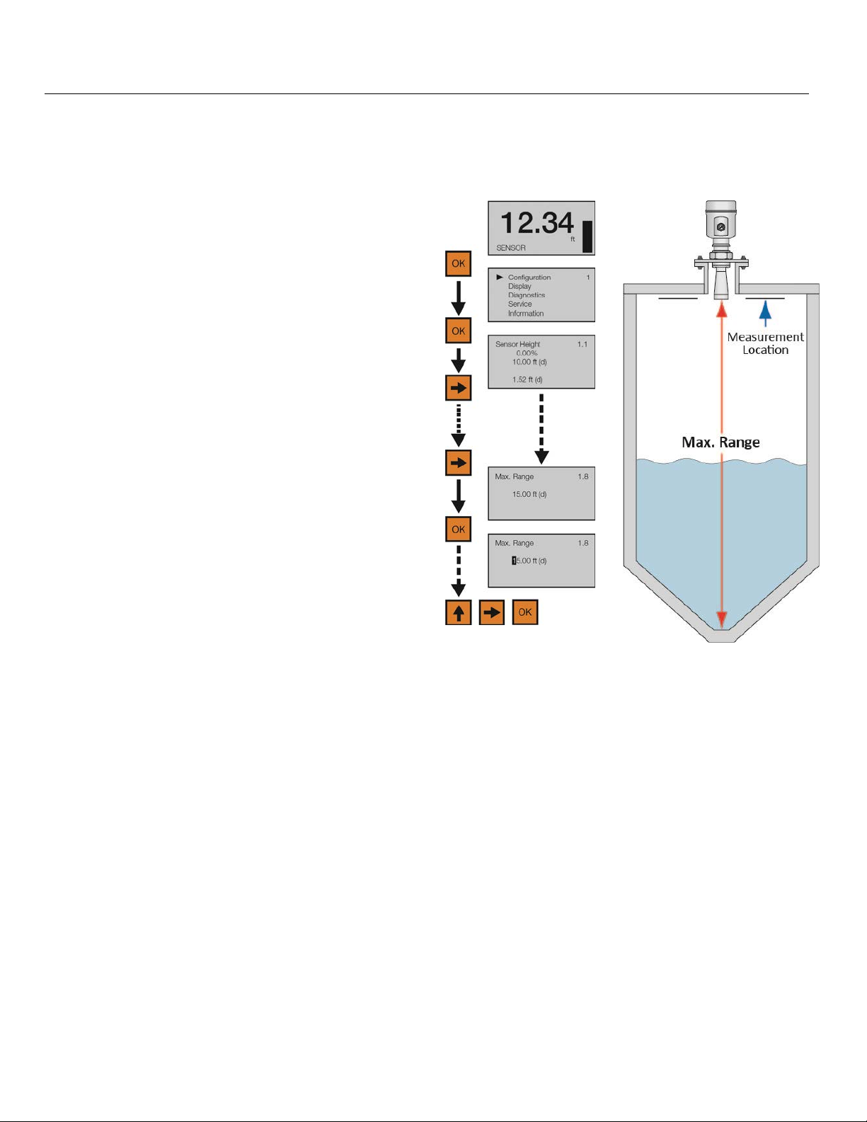
Configuration Using Display (continued) Step Five
STEP 5 - SET THE MAX. RANGE (MAXIMUM RANGE)
This function sets the maximum operational range for the sensor. This setting defines the maximum distance
that the sensor will detect valid echo returns.
1) From the Main Screen, press OK to advance into
the Main Menu.
2) Press OK to advance into the Configuration Menu.
3) Press Right Arrow repeatedly until the menu
shows Max. Range.
4) Press OK to edit Max. Range value. The first
segment will be highlighted.
5) Press Right Arrow to move one segment to the
right. Right Arrow will scroll left to right and then
back to the first segment.
6) Press Up Arrow to increase the value of the number highlighted. Up Arrow will scroll from 0 to 9 and back
again.
7) When the value is correct, press OK to save the setting.
8) When done, press ESC to return to the Main Menu, and press ESC a second time to return to the Main
Screen or; if you want to advance directly into Dead Band, press Right Arrow repeatedly until Dead Band
appears.
MN301900 Rev B 51 |
Page 52
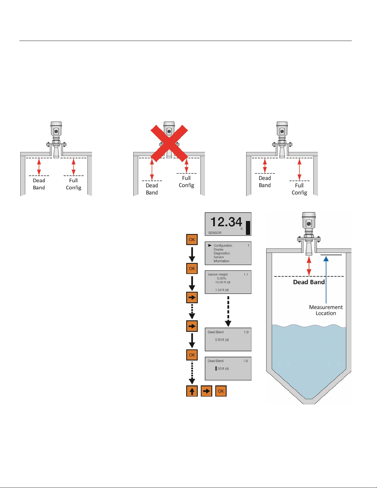
Configuration Using Display (continued) Step Five
STEP 6 - SET THE DEAD BAND
This function sets the Dead Band for the sensor. This setting defines the minimum distance that the sensor will
detect valid echo returns. While the Dead Band setting is typically configured to be equal with or slightly above
(higher in the tank) the Full Configuration setting (20 mA), its functions independently of Full Configuration.
Note: If the Dead Band setting is placed below the Full Configuration setting, then the sensor will not measure
above the Dead Band.
Dead Band Equals Full Config. Dead Band Below Full Config. Dead Band Above Full Config.
1) From the Main Screen, press OK to advance into
the Main Menu.
2) Press OK to advance into the Configuration
Menu.
3) Press Right Arrow repeatedly until menu shows
Dead Band.
4) Press OK to edit Dead Band value. The first
segment will be highlighted.
5) Press Right Arrow to move one segment to the
right. Right Arrow will scroll left to right and then
back to the first segment.
6) Press Up Arrow to increase the value of the number highlighted. Up Arrow will scroll from 0 to 9 and back again.
7) When the value is correct, press OK to save the setting.
8) When done, press ESC to return to the Main Menu, and press ESC a second time to return to the Main
Screen.
| 52 MN301900 Rev B
Page 53
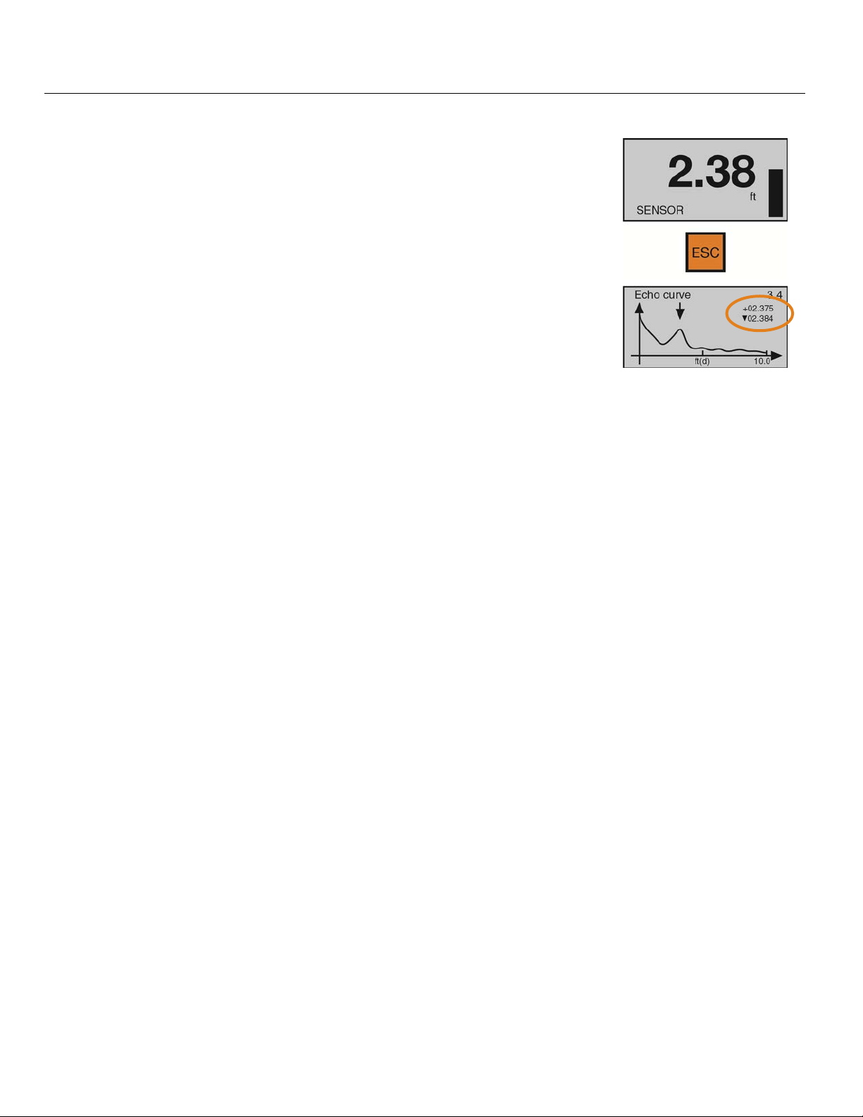
Configuration Using Display (continued) Step Five
STEP 7 - CHECK THE ECHO CURVE
This function displays the primary echo return(s) that the sensor is seeing
graphically, the location and amplitude of the return(s), and the numeric air gap
distance from the sensor’s measurement location to the liquid level below.
Note: This step should only be performed after having completed the prior six
configuration steps with the sensor installed on the tank. Additionally, if the
sensor was installed in a stand pipe or sight glass, now go forward to Section
Seven and turn on the still well function (Sensor Installed in a Stand Pipe or
Sight Glass) before continuing with this step.
1) From the Main Screen, press ESC and the Echo Curve Screen will appear.
The curve graphically represents the primary echo return(s) amplitude (Yaxis) over distance (X-axis). Above the echo return peak is a floating arrow
and triangle symbol (which under normal conditions are often merged
together or seen as a single triangle because it’s the larger of the two
symbols). The arrow represents the measured liquid level and the triangle
represents the peak amplitude location of the echo return. Under normal
conditions, expect to see a stable triangle (or overlapping arrow and
triangle) floating above a pronounced peak at the expected air gap distance
between the measurement location and liquid level.
2) In the upper right hand corner of the screen are two lines of numbers that
represent the air gap distance from the measurement location to the liquid
level (arrow) on the top, and peak amplitude location (triangle) of the echo
return on the bottom. Under normal conditions, these values should be
relatively close to one another and consistent with the expected air gap
distance between the measurement location and liquid level.
3) Assuming that the sensor is properly installed, if the measured liquid level
and peak amplitude location data (symbols and values) are unstable,
substantially different from one another and/or inconsistent with the actual
air gap distance, then this likely indicates that the sensor requires
additional process adjustment(s) described in the following Section Six.
4) When done, press ESC to return to the Main Menu.
MN301900 Rev B 53 |
Page 54
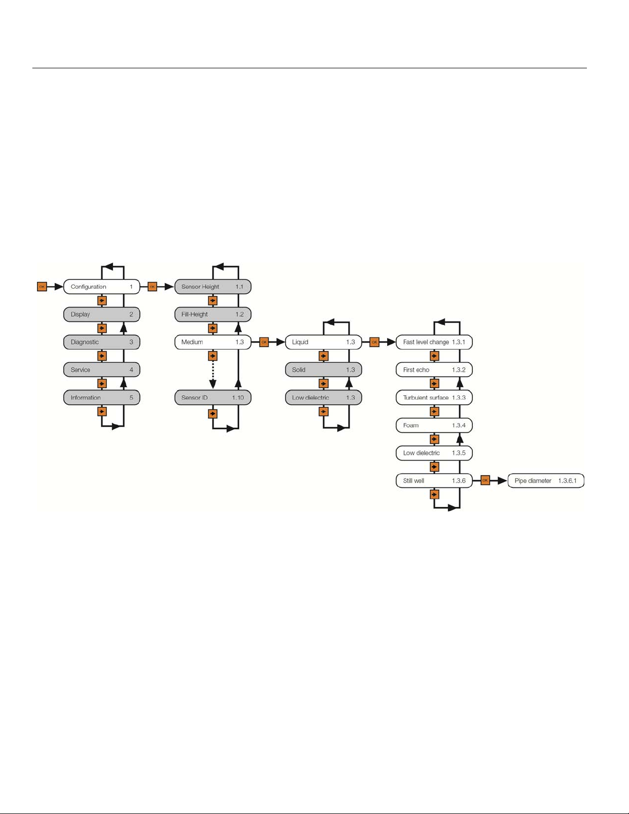
Process Adjustments (using Display) Step Six
PROCESS ADJUSTMENTS OVERVIEW
These optional functions are intended to improve sensor performance in applications with the below process
and/or installation characteristics. Note: These adjustments should only be performed when (after having
completed the seven configuration steps described in Section Five with the sensor installed on the tank) the
sensor is not performing to your satisfaction. Where so, perform the following applicable Process Adjustments.
1) Fast Level Change - Fast Filling or Emptying of the Liquid
2) First Echo - Liquid Requiring First Echo Adjustment
3) Turbulent Surface - Liquid Surface is Turbulent or Agitated Surface
4) Foam - Foam on the Surface of the Liquid
5) Low Dielectric - Liquids with Low Dielectric
6) Still Well - Sensor Installed in a Stand Pipe or Sight Glass
| 54 MN301900 Rev B
Page 55
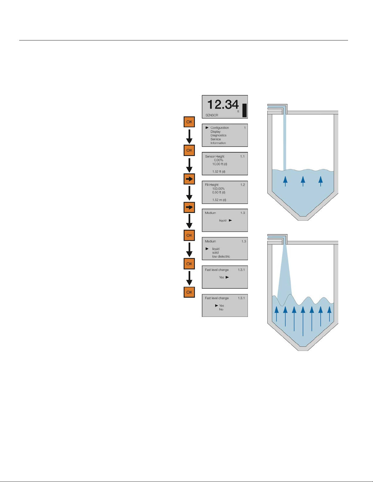
Process Adjustments (using Display, continued) Step Six
FAST FILLING OR EMPTYING OF LIQUID (FAST LEVEL CHANGE)
If the speed of media level rise or fall within the tank is greater than a rate of 1” per second (25.4mm/sec), set
Fast Level Change to Yes. Note: Fast filling or emptying can occur when multiple pumps are operating or
when a weather event increases the amount of media entering the tank.
Normal Level Change
1) From the Main Screen, press OK to advance
into the Main Menu.
2) Press OK to advance into the Configuration
Menu.
3) Press Right Arrow to advance from Sensor
Height to Fill-Height.
4) Press Right Arrow to advance from Fill-
Height to Medium.
5) Press OK to advance into Medium. Liquid,
Solid, Low Dielectric will appear.
6) Press OK to advance into Liquid. Fast Level
Change will appear first.
7) Press OK to advance into Fast Level Change.
8) Press Right Arrow to change the Fast Level
Change setting.
9) When the setting is correct, press OK to save.
10) When done, press ESC to return to Medium,
press ESC again to return to the Configuration
Menu, and press ESC a third time to return to
the Main Screen or; If you want to advance
directly into Turbulent Surface, press Right
Arrow repeatedly until Turbulent Surface
appears.
Fast Level Change
MN301900 Rev B 55 |
Page 56
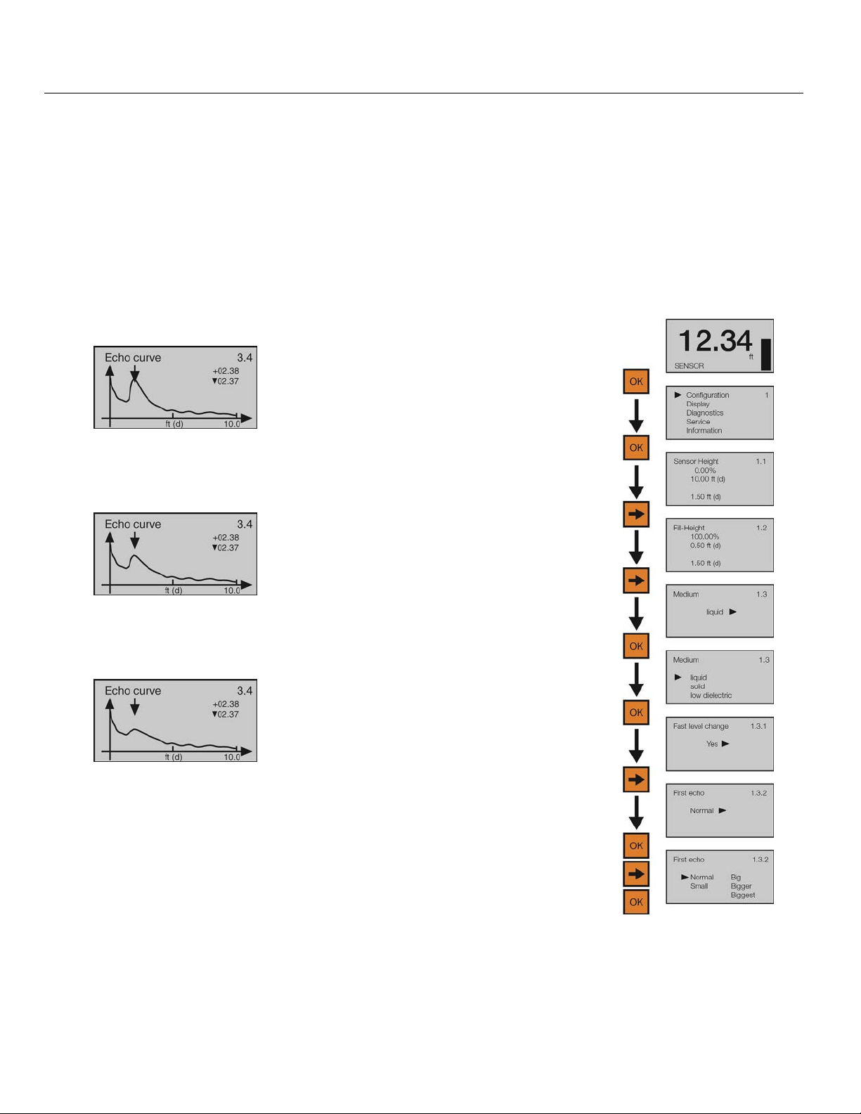
Process Adjustments (using Display, continued) Step Six
LIQUIDS REQUIRING FIRST ECHO ADJUSTMENT (FIRST ECHO)
This function increases or decreases the peak strength of the sensor’s First Echo return, and should only be
performed if: 1) The liquid has a very high dielectric constant value and primarily stays in the near full range of
the tank, resulting in a very high First Echo peak strength or; 2) Process conditions, such as when the media
has a very low dielectric constant value, or when obstructions, heavy foam or turbulence exist in the tank,
resulting in little or no First Echo peak strength. Note: Under condition one (Example 1), it can be beneficial to
decrease the First Echo peak strength. Under condition two (Example 3), it can be beneficial to increase the
First Echo peak strength.
Example 1
First Echo peak is very strong
and can be reduced.
Example 2
First Echo peak is normal and
no adjustment is required.
Example 3
First
Echo peak is weak and can
be increased.
1) From the Main Screen, press OK to
advance into the Main Menu.
2) Press OK to advance into the
Configuration Menu.
3) Press Right Arrow to move from Empty
Configuration to Full Configuration.
4) Press Right Arrow to move from Full
Configuration to Medium.
5) Press OK to advance into Medium and
Liquid, Solid & Low Dielectric will
appear.
6) Press OK to advance into Solids and
Fast Level Change will appear.
7) Press Right Arrow to move from Fast
Level Change to First Echo.
8) Press OK to advance into First Echo.
9) Press Right Arrow to change the First
Echo setting.
10) When setting is correct, press OK to
save.
First Echo Adjustments
Normal - No adjustment
Small - Decrease by 10 dB
Big - Increase by 10 db
Bigger - Increase by 20 db
Biggest - Increase by 40 db
11) When done, press ESC to return to
Medium, press ESC again to return to
the Configuration Menu, and press ESC
a third time to return to the Main Screen
or; If you want to advance directly into
Large Repose Angle, press Right
Arrow repeatedly until Large Repose
Angle.
| 56 MN301900 Rev B
Page 57
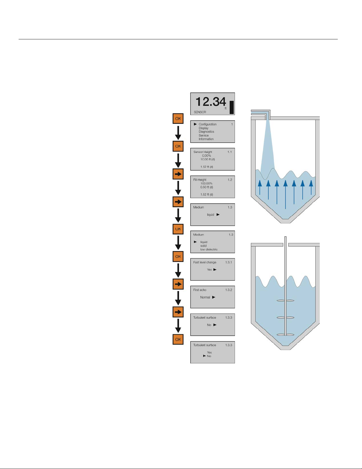
Process Adjustments (using Display, continued) Step Six
LIQUID SURFACE IS TURBULENT OR AGITATED (TURBULENT SURFACE)
If the liquid surface is turbulent or agitated, set Turbulent Surface to Yes. Note: Turbulent or agitated surfaces
can occur when tanks are filled from the top without a down pipe, or when a mixer or air agitation is used within
the tank.
Turbulence from Tank
Fill
1) From the Main Screen, press OK to
advance into the Main Menu.
2) Press OK to advance into the
Configuration Menu.
3) Press Right Arrow to advance from
Sensor Height to Fill-Height.
4) Press Right Arrow to advance from Fill-
Height to Medium.
5) Press OK to advance into Medium.
Liquid, Solid, Low Dielectric will appear.
6) Press OK to advance into Liquid. Fast
Level Change will appear first.
7) Press Right Arrow to advance from Fast
Level Change to First Echo.
8) Press Right Arrow to advance from First
Echo to Turbulent Surface.
9) Press OK to advance into Turbulent
Surface.
10) Press Right Arrow to change the
Turbulent Surface setting.
Agitation from Mixer
11) When the setting is correct, press OK to save.
12) When done, press ESC to return to Medium, press ESC again to return to the Configuration Menu,
and press ESC a third time to return to the Main Screen or; If you want to advance directly into Foam,
press Right Arrow repeatedly until Foam appears.
MN301900 Rev B 57 |
Page 58
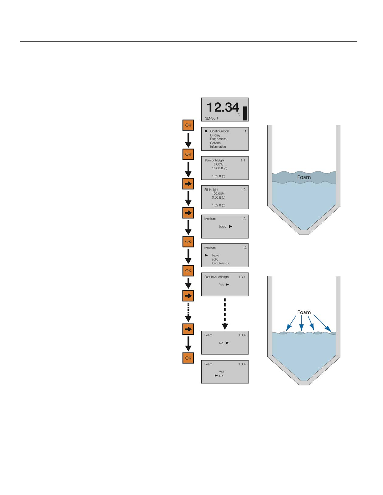
Process Adjustments (using Display, continued) Step Six
FOAM ON THE SURFACE OF THE LIQUID (FOAM)
If the entire liquid surface is covered with foam, set Foam to Yes. This is not necessary if the liquid surface is
partially covered with foam. Note: Foam can occur when tanks are filled from the top without a down-fill pipe,
or when a mixer or air agitation is used within the tank.
Heavy Foam – If foam
covers the entire surface of
1) From the Main Screen, press OK to
advance into the Main Menu.
2) Press OK to advance into the
Configuration Menu.
3) Press Right Arrow to advance from
Sensor Height to Fill-Height.
the liquid, set Foam to Yes.
4) Press Right Arrow to advance from Fill-
Height to Medium.
5) Press OK to advance into Medium.
Liquid, Solid, Low Dielectric will appear.
6) Press OK to advance into Liquid. Fast
Level Change will appear first.
7) Press Right Arrow repeatedly until Foam
1.3.4 appears.
8) Press OK to advance into Foam.
9) Press Right Arrow to change the Foam
setting.
Light Foam – If foam
partially covers the surface
of the liquid, set Foam to
No.
10) When the setting is correct, press OK to save.
11) When done, press ESC to return to Medium, press ESC again to return to the Configuration Menu, and
press ESC a third time to return to the Main Screen or; If you want to advance directly into Still Well,
press Right Arrow repeatedly until Still Well appears.
| 58 MN301900 Rev B
Page 59
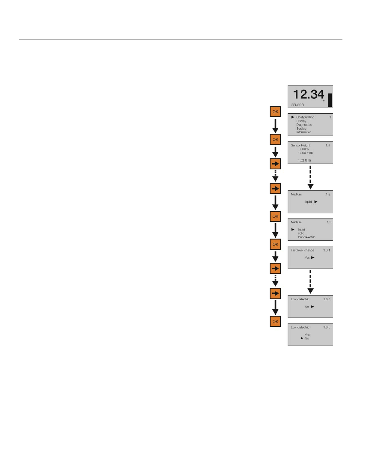
Process Adjustments (using Display, continued) Step Six
LIQUIDS WITH LOW DIELECTRIC (LOW DIELECTRIC)
Used when the liquid has a low dielectric constant (typically under 10). Selections are YES or NO. Default is
NO.
1) From the Main Screen, press OK to advance into the Main Menu.
2) Press OK to advance into the Configuration Menu.
3) Press Right Arrow repeatedly until menu shows Medium.
4) Press OK to advance into Medium. Liquid, Solid & Low Dielectric will
appear.
5) Press OK to advance into Solids. Fast Level Change will appear first.
6) Press Right Arrow repeatedly until Low Dielectric appears.
7) Press OK to advance into Low Dielectric.
8) Press Right Arrow to change the setting from No to Yes.
9) Press OK to enter the Pipe Diameter.
10) When the value is correct, press OK to save.
11) When done, press ESC to return to Medium, press ESC again to return to the Configuration Menu, and
press ESC a third time to return to the Main Screen.
MN301900 Rev B 59 |
Page 60
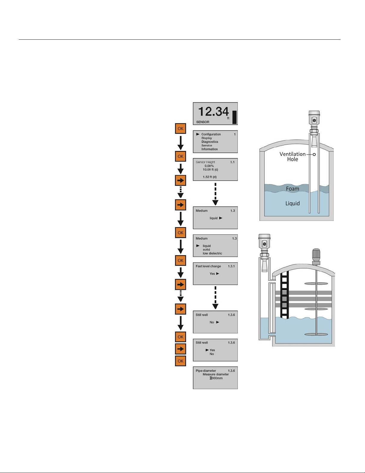
Process Adjustments (using Display, continued) Step Six
SENSOR INSTALLED IN A STAND PIPE OR BYPASS CHAMBER - LIQUIDS ONLY (STILL WELL)
If the sensor is installed in a metal stand pipe (still well) or metal bypass chamber, set Still Well to yes and enter
the inner Pipe Diameter dimension. Note: The Pipe Diameter will be entered in millimeters. For example, a 3”
pipe can have an inner diameter of 3.042”. To convert inches to mm, multiple inches by 25.4mm. Thus, a
3.042” pipe inner diameter equals 77.26mm. You would then enter the value of 77mm.
Still Well or Stand Pipe
1) From the Main Screen, press OK to advance
into the Main Menu.
2) Press OK to advance into the Configuration
Menu.
3) Press Right Arrow repeatedly until menu
shows Medium.
4) Press OK to advance into Medium. Liquid,
Solid & Low Dielectric will appear.
5) Press OK to advance into Liquid. Fast Level
Change will appear first.
6) Press Right Arrow repeatedly until Still Well
appears.
7) Press OK to advance into Still Well.
8) Press Right Arrow to change the setting from
No to Yes.
9) Press OK to enter the Pipe Diameter.
10) Use the Right Arrow to move one segment to
the right. Right Arrow will scroll left to right
and then back to the first segment.
Bypass Chamber
11) Use the Up Arrow to increase the value of the number highlighted. Up Arrow will scroll from 0 to 9 and
back again. When the value is correct, press OK to save.
12) When done, press ESC to return to Medium, press ESC again to return to the Configuration Menu, and
press ESC a third time to return to the Main Screen.
| 60 MN301900 Rev B
Page 61
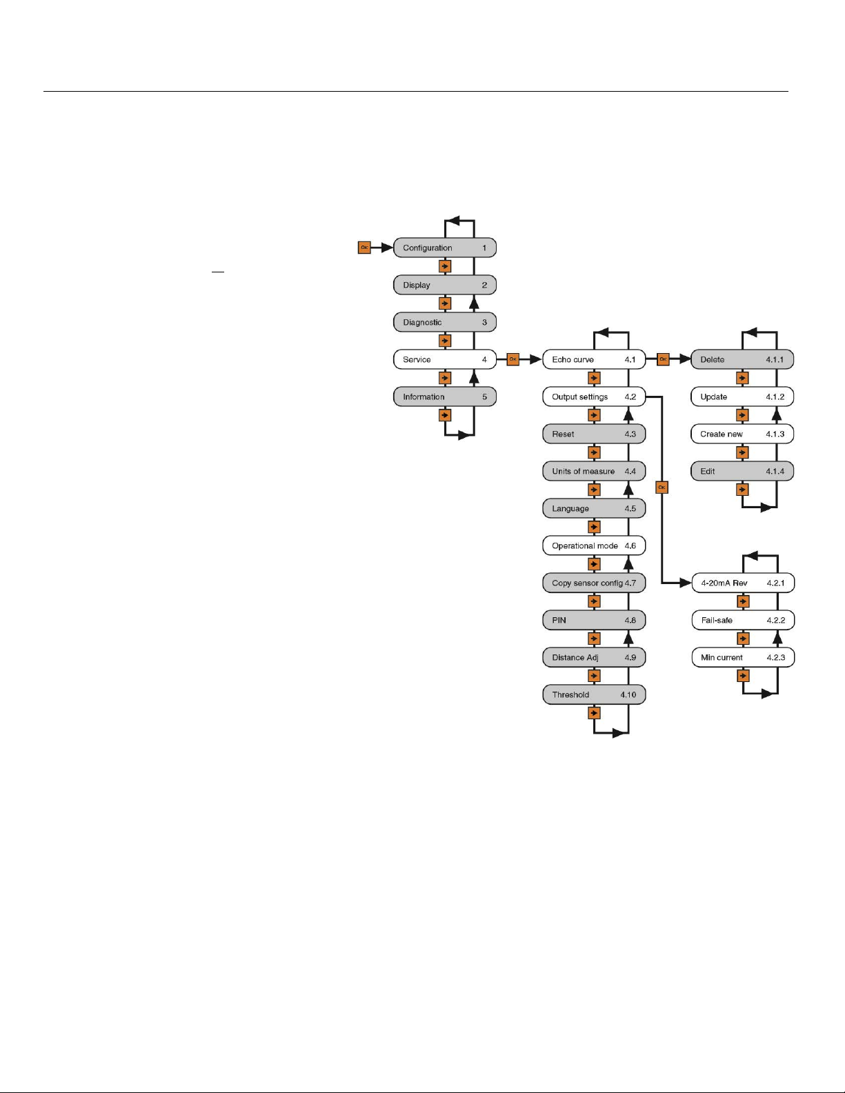
Advanced Adjustments Step Seven
ADVANCED ADJUSTMENTS OVERVIEW
These optional functions are used to change the sensor output characteristics, or Create a False Echo Curve to
filter out false echo returns within the tank (improving sensor performance), or Update an existing False Echo
Curve filter if the original filter was not created during an empty tank condition.
1) 4-20 mA Rev Output - Reverses the
current output from 4mA @ bottom and
20mA @ top of tank to
and 4mA @ top of the tank.
2) Fail-Safe - Allows for the presetting of
the current output when a sensor failure
occurs. Options are no change to
current, 20.5mA or 22mA.
3) Minimum Current - Sets the minimum
current output for the sensor. Options
are 4.0mA or 3.9mA.
4) HART
®
Operational Mode – Sets the
device address as well as sets the
current draw for the device.
20mA @ bottom
5) Create a new False Echo Curve - A
method to filter out false echo returns
within the tank. This should be
performed when the tank is at its lowest
level (empty).
6) Update an existing False Echo Curve
- A method to update an existing False
Echo Curve to include a lower section of
the tank that was not exposed during
the creation of the original Echo Curve.
Note: If you don't know the location
(level position) or validity of the original
False Echo Curve, it is recommended to
delete the original Echo Curve, and then
create a new False Echo Curve (versus
updating an existing False Echo Curve).
MN301900 Rev B 61 |
Page 62
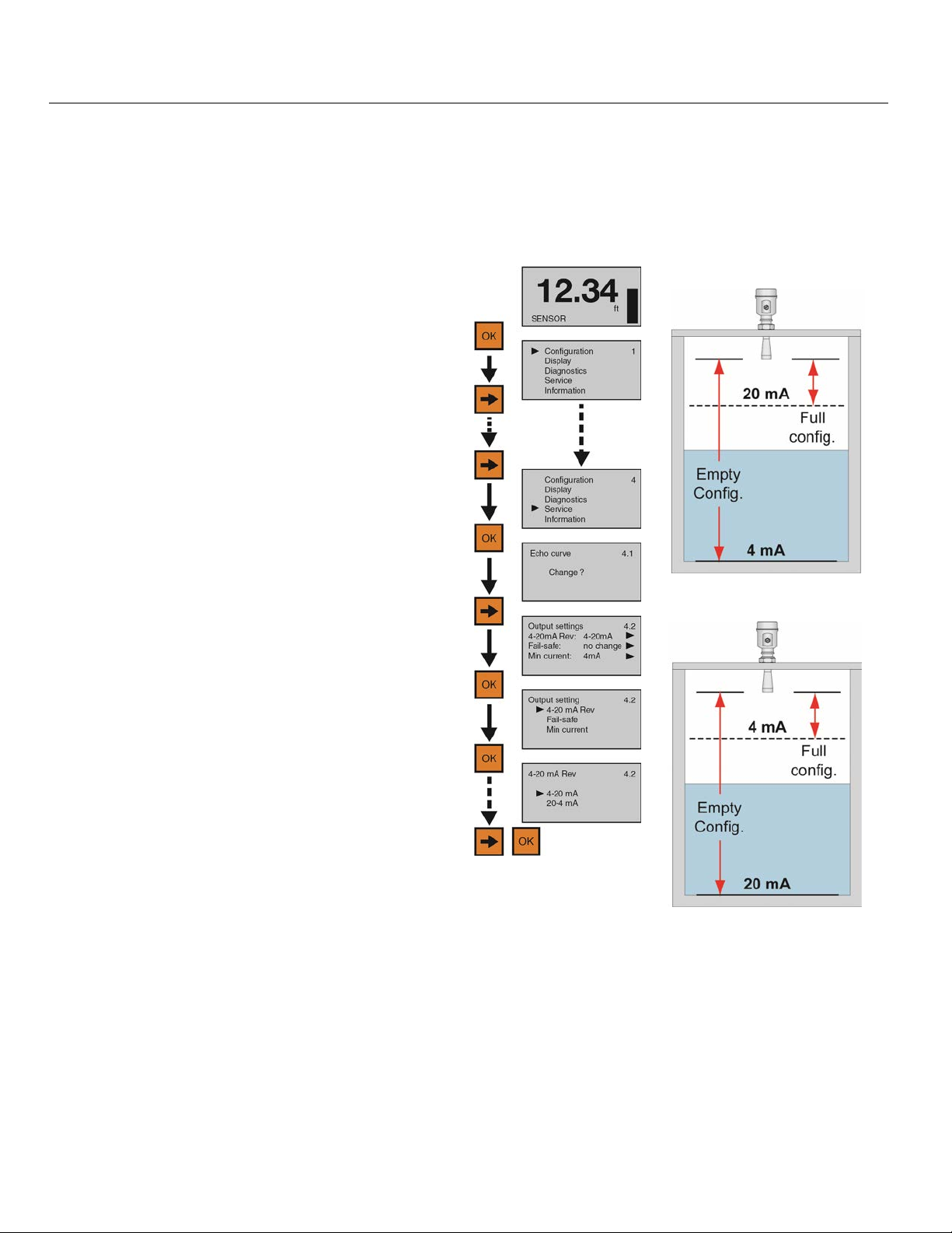
Advanced Adjustments (continued) Step Seven
4-20 MA REVERSE OUTPUT
This function sets the current output at either 4-20 mA or 20-4 mA. Selecting 4-20 mA sets the output with 4mA
@ bottom and 20mA @ top of the tank. This is the standard output used in the majority of applications.
Selecting 20-4 mA sets the output with 20mA @ bottom and 4mA @ top of the tank. This is an optional output
sometimes used in applications where the level is maintained at a high level.
4 to 20 mA Output
1) From the Main Screen, press OK to advance
into the Main Menu.
2) Press Right Arrow repeatedly until the arrow
is next to Service.
3) Press OK to advance into Service Menu.
4) Press Right Arrow to move from Echo Curve
20 to 4mA Output
to Output Current.
5) Press OK to advance into Output Current.
6) Press OK to advance into 4-20mA Rev.
7) Press Right Arrow to change the setting
between 4-20mA and 20-4mA.
8) When the setting is correct, press OK to
save.
9) When done, press ESC to return to the Service Menu and press ESC a second time to return to the Main
Screen or; if you want to advance directly into Fail-Safe, press OK and then Right Arrow until Fail-Safe
appears. When done, press ESC to return to the Service Menu and press ESC a second time to return to
the Main Screen or; if you want to advance directly into Fail-Safe, press OK and then Right Arrow until
Fail-Safe appears.
| 62 MN301900 Rev B
Page 63
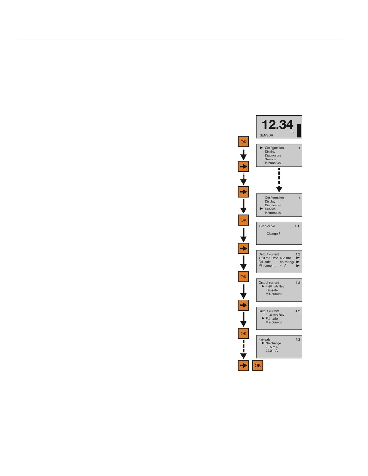
Advanced Adjustments (continued) Step Seven
FAIL-SAFE OUTPUT
This function is used to set the current output to a designated state if the sensor loses measurement
confidence. Selecting No Change will hold the current at its last valid current output. Selecting 20.5mA will
force the current to jump to 20.5mA. Selecting 22.5 mA will force the current to jump to 22.5 mA. Note: The
latter two high current output states are above the standard 4-20 mA operational range, and can be used to
indicate that a failure has occurred.
1) From the Main Screen, press OK to advance into the
Main Menu
2) Press Right Arrow repeatedly until the arrow is next
to Service.
3) Press OK to advance into Service Menu and Echo
Curve will appear.
4) Press Right Arrow to move from Echo Curve to
Output Current.
5) Press OK to advance into Output Current menu.
6) Press Right Arrow to move from Reverse 4-20mA to
Fail-safe.
7) Press OK to enter Fail-safe.
8) Press Right Arrow to change the setting between
No change, 20.5mA and 22.0mA.
9) When the setting is correct, press OK to save.
10) When done, press ESC to return to the Service Menu and press ESC a second time to return
to the Main Screen or; if you want to advance directly into Min Current, press OK and then
Right Arrow until Min Current appears.
MN301900 Rev B 63 |
Page 64
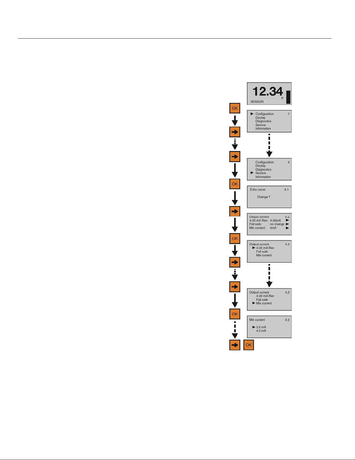
Advanced Adjustments (continued) Step Seven
MINIMUM CURRENT OUTPUT
This function sets the minimum current output for the sensor at either 4.0mA or 3.9mA. Note: 4.0mA is the
default minimum current output and is used in the majority of applications.
1) From the Main Screen, press OK to advance into the
Main Menu.
2) Press Right Arrow repeatedly until the arrow is next
to Service.
3) Press OK to advance into Service Menu and Echo
Curve will appear.
4) Press Right Arrow to move from Echo Curve to
Output Current.
5) Press OK to advance into Output Current menu.
6) Press Right Arrow repeatedly to move from Reverse
4-20mA to Min Current.
7) Press OK to enter Min Current.
8) Press Right Arrow to change the setting between
3.9mA and 4.0mA.
9) When the setting is correct, press OK to save.
10) When done, press ESC to return to the Service Menu and press ESC a second time to return
to the Main Screen.
| 64 MN301900 Rev B
Page 65
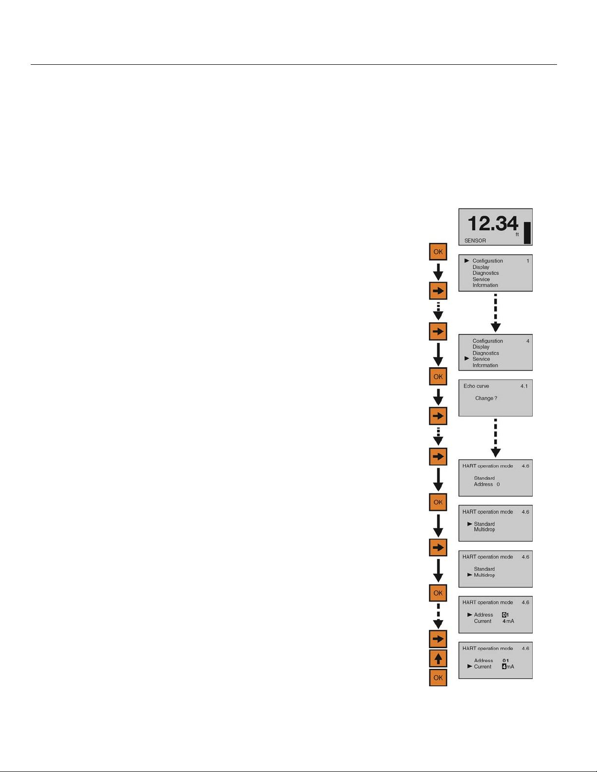
Advanced Adjustments (continued) Step Seven
HART® OPERATION MODE
This feature sets the HART® address for operation as well as setting the output current for HART® operation.
HART
®
Address
o Standard – address 0 (default). Use in a single device per loop configuration.
o Multi-drop – addresses 1 to 15. Allows for multiple sensors to share the same wiring. Each sensor must
have a unique address. The current loop will hold when address is set from 1 to 15.
HART
®
Current
o Standard – 0 (default). 4-20 mA output is active when address is set to 0.
o Multi-drop – Choose between 4mA or 8mA as the static current. Power supply must be able to provide
power for all devices placed on the loop at the set current. Default is 4mA.
1) From the Main screen, Press Enter to enter Menu.
2) Press Right Arrow repeatedly until arrow is next to Service.
3) Press Enter to advance into Service menu.
4) Press Right Arrow repeatedly until HART
®
5) Press Enter to advance into HART
Operation Mode.
®
Operation Mode appears.
6) Press Right Arrow to move arrow next to Multi-Drop.
7) Press Enter to enter Multi-Drop and set the HART
®
address.
a) Use the Up Arrow to increase the value of the number highlighted.
b) Use the Right Arrow to move one segment to the right.
8) When the address is set, press Enter to save the new address and
jump to Current.
a) Use the Up Arrow to change the current value between 4mA & 8mA.
b) When the current is set, press Enter to save the new current.
When the setting is correct for your application, press Enter again to return
to HART
®
Operational Mode, press the ESC button to return to Service
Menu and press ESC a second time to return to the Main screen.
MN301900 Rev B 65 |
Page 66
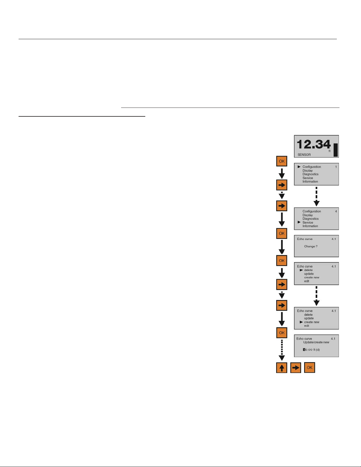
Advanced Adjustments (continued) Step Seven
CREATE A NEW FALSE ECHO CURVE
Obstructions in the tank (mixer blades, side wall weld joints or material build-up, submersible pumps, piping,
other apparatus) or tall tank risers or installation fittings can create false echo returns that impair the sensor’s
measurement. This function maps all echo returns within the tank, differentiating between good and false
echoes, and stores those identified as false into the False Echo Curve, so they will not be considered in the
level measurement. Note: A False Echo Curve should only be performed when the tank is empty so that all
false reflections will be detected. Before starting, measure and note the exact distance from the sensor’s
measurement location to the liquid surface. Setting the display to Distance will show the distance from the
Sensor to the liquid surface. Enter this value under Step 6. Setting the distance value too large or too short
can force the sensor into ignoring the true level.
1) From the Main Screen, press OK to advance into the Main Menu.
2) Press Right Arrow repeatedly until the arrow is next to Service.
3) Press OK to advance into Service Menu and Echo Curve will appear.
4) Press OK to make a change to the Echo Curve settings.
5) Press Right Arrow repeatedly until the arrow is next to Create New.
6) Press OK to advance into Create New. Enter the distance from the sensor’s
measurement location to the liquid surface.
7) Use the Right Arrow to move one segment to the right. The Right Arrow will
scroll left to right and then back to the first segment.
8) When the value is correct, press OK to save the setting and begin the False Echo Curve mapping. The
process may take a few minutes. When complete, the display will return to the Echo Curve screen.
9) When done, press ESC to return to the Service Menu and press ESC a second time to return to the Main
Screen.
10) From the Main Screen, press ESC and the Echo Curve Screen will appear. Follow the Check Echo Curve
procedure described at the end of Section Five to confirm that the sensor is performing correctly.
| 66 MN301900 Rev B
Page 67
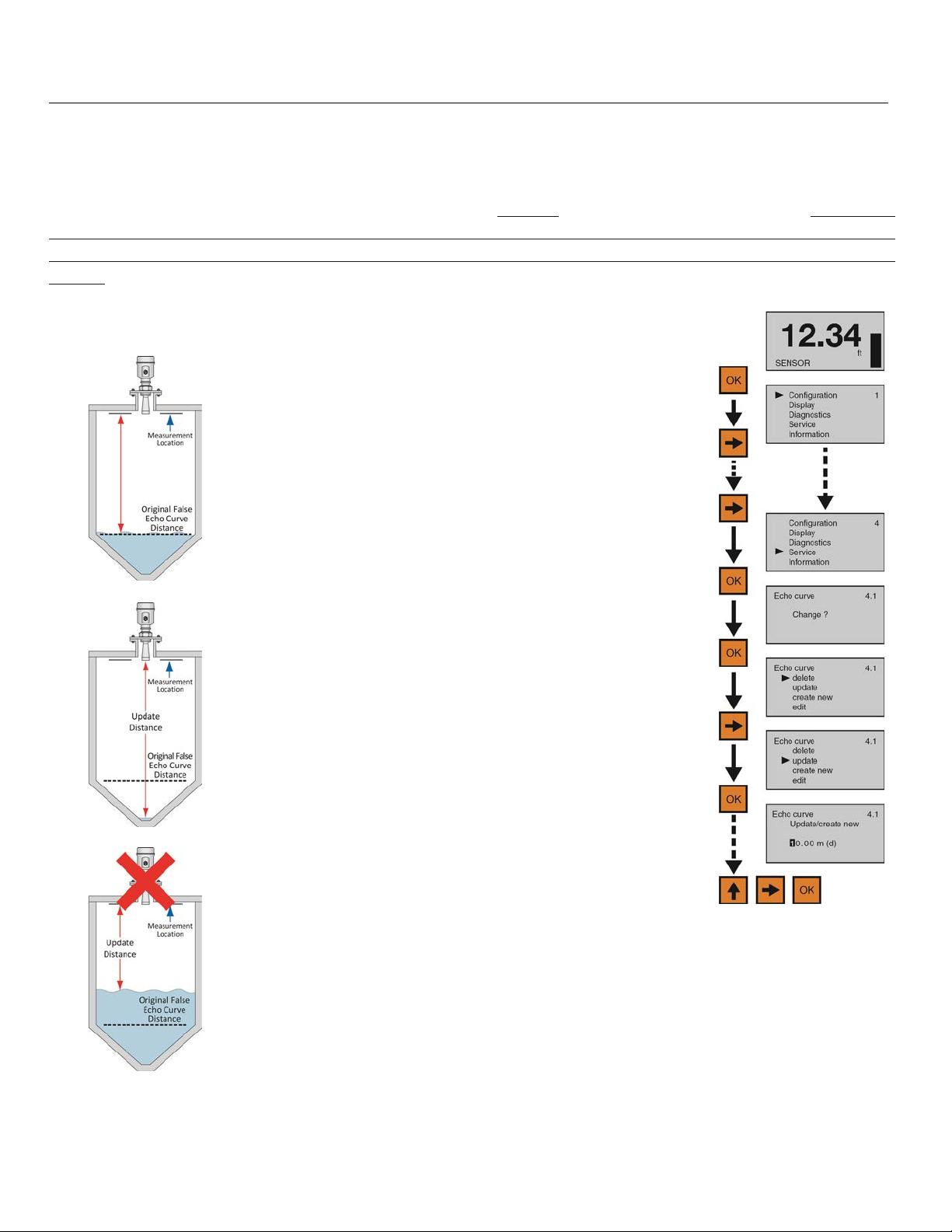
Advanced Adjustments (continued) Step Seven
UPDATE AN EXISTING FALSE ECHO CURVE
This function enables an Existing False Echo Curve to be updated under the circumstances that the curve was
created when the level was higher than an empty tank condition. Note: This function should only be performed
to update an Existing False Echo Curve when the level is BELOW
this function to update an Existing False Echo Curve when the level is above the original False Echo Curve.
Before starting, measure and note the exact distance from the sensor’s measurement location to the liquid
surface. Setting the distance value too large or too short can force the sensor into ignoring the true level.
Original False Echo
Curve
1) From the Main Screen, press OK to advance into the
Main Menu.
2) Press Right Arrow repeatedly until the arrow is next
to Service.
3) Press OK to advance into Service Menu and Echo
Curve will appear.
4) Press OK to make a change to the Echo Curve
settings.
the original False Echo Curve. Do not use
Good Update
Bad Update
5) Press Right Arrow repeatedly until the arrow is next to
Update.
6) Press OK to advance into Update. Enter the actual
distance from the sensor’s measurement location to
the liquid surface.
7) Use the Right Arrow to move one segment to the
right. The Right Arrow will scroll left to right and then
back to the first segment.
8) Use the Up Arrow to increase the value of the number
highlighted. The Up Arrow will scroll from 0 to 9 and
back again.
9) When the value is correct, press OK to save the
setting and begin the False Echo Curve mapping.
The process may take a few minutes. When
complete, the display will return to the Echo Curve
screen.
10) When done, press ESC to return to the Service Menu
and press ESC a second time to return to the Main
Screen.
11) From the Main Screen, press ESC and the Echo
Curve Screen will appear. Follow the Check Echo
Curve procedure described at the end of Section Five
to confirm that the sensor is performing correctly.
MN301900 Rev B 67 |
Page 68

Troubleshooting Step Eight
TROUBLESHOOTING OVERVIEW
These functions provide troubleshooting information; enable Echo Curve adjustments and deletion of settings.
1) Measurement Status
a) Displays the signal strength (dB) of the echo returns and the functional status of the sensor including
diagnostic error codes.
2) Peak Values
a) Displays the lowest and highest level height that the sensor has measured in distance (d).
3) Simulation
a) Simulates the 4-20mA current output from percent of span, current or distance inputs.
4) First Echo Adjustment
a) Provides the ability to increase or decrease the peak signal strength of the First Echo return.
5) Echo Curve Zoom
a) Provides the ability to zoom in and magnify the Echo Curve over a specified range.
6) False Echo Curve Delete
a) Provides the ability to delete a saved False Echo Curve.
7) Reset
a) Provides the ability to reset configuration settings and memory.
| 68 MN301900 Rev B
Page 69
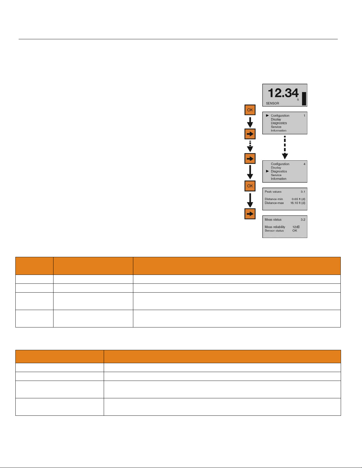
Troubleshooting (continued) Step Eight
MEASUREMENT STATUS
This function displays the signal strength (dB) of the echo returns and the operational status of the sensor
including diagnostic error codes.
1) From the Main Screen, press OK to advance into the Main
Menu.
2) Press Right Arrow repeatedly until the arrow is next to
Diagnostics.
3) Press OK to advance into Diagnostics.
4) Press Right Arrow to switch to Measurement Status.
5) Measurement reliability indicates the decibel (dB) strength of
RF energy that’s reflecting back to the sensor less any
noise. For reliable function, the dB value should be ≥ 10 dB.
6) Sensor status indicates the functional status of the sensor
(either OK or error code)
7) When done, press ESC to return to the Service Menu and
press ESC a second time to return to the Main Screen.
SENSOR STATUS ERROR CODES
Error
Code
Problem Solution
E11 Insufficient power Check power supply
E12 Open circuit Check wiring for open circuit
E14
E15 or
E17
Weak echo return (<
10dB)
ROM error Contact your distributor
Check for obstacles under the sensor, either clear the obstacle, move
the sensor or perform a False Echo Curve
CURRENT OUTPUT CONDITIONS
Problem Solution
Sensor output < 3.9mA Check wiring for open circuit
Sensor output > 22mA Check wiring for short circuit
Sensor output reaches 4mA
before the tank is empty
Sensor output will not reach
4mA
Check the Empty Configuration setting, and if incorrect, extend the setting to the
empty tank position
Check the Range setting, and if incorrect, extend the setting to or slightly below
the Empty Configuration setting
MN301900 Rev B 69 |
Page 70
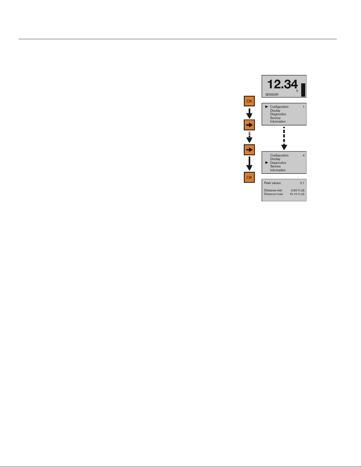
Troubleshooting (continued) Step Eight
PEAK VALUES
This function displays the lowest and highest level height that the sensor has measured in distance (d).
1) From the Main Screen, press OK to advance into the Main
Menu.
2) Press Right Arrow repeatedly until arrow is next to
Diagnostics.
3) Press OK to advance into Diagnostics and view Peak
Values.
4) Distance-min is the lowest measured level and Distance-max is the highest measured level.
Confirm that these values are within the sensor’s operational range.
5) If the values appear too high or too low, check the tank for obstructions that could cause that
problem.
6) When done, press ESC to return to the Service Menu and press ESC a second time to return to
the Main Screen.
| 70 MN301900 Rev B
Page 71
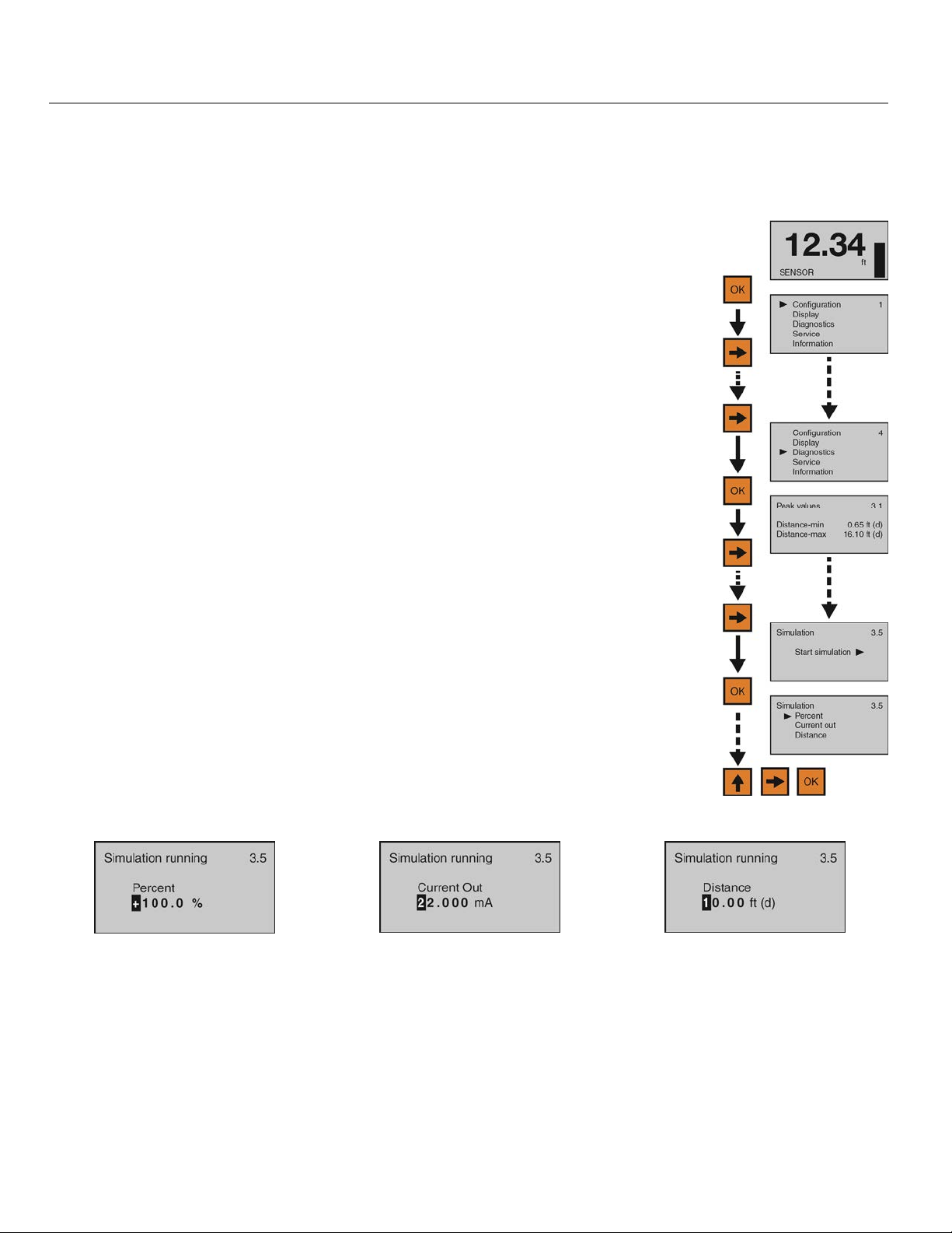
Troubleshooting (continued) Step Eight
SIMULATION
This function simulates the 4-20mA current output, when the sensor is configured and installed on the tank, but
the level cannot be changed easily for testing. Percent (of span), Current Output or Distance can be used as the
input method to set the current output.
1) From the Main Screen, press OK to advance into the Main Menu.
2) Press Right Arrow repeatedly until the arrow is next to Diagnostics.
3) Press OK to advance into Diagnostics.
4) Press Right Arrow repeatedly until Simulation appears.
5) Press OK to advance into Simulation.
6) Use the Right Arrow to scroll among the three simulation methods (Percent,
Current Out or Distance).
7) Use OK to select the method of simulation.
8) Upon selection of a method, the simulation will start and the current output will
proportionately reflect the value shown. While the simulation is running, the value
can be changed.
9) Use the Right Arrow to move one segment to the right. The Right Arrow will
scroll left to right and then back to the first segment.
10) Use the Up Arrow to increase the value of the number highlighted. The Up Arrow
will scroll from 0 to 9 and back again.
11) When the value is correct, press OK and the current output will reflect the value
shown.
12) When done, press ESC to return to Simulation, press ESC again to return to the
Configuration Menu, and press ESC a third time to return to the Main Screen.
Percent Current Output Distance
This method uses percentage of
span (0-100%) to set the current
output (4-20mA) between the
Empty and Full Configuration
values with 100% equal to 20 mA
This method directly sets the
current output (4-20mA) to the
desired value.
This method uses distance from
the sensor’s measurement location
to set the current output (4-20mA)
between the Empty and Full
Configuration values.
and 0% equal to 4mA.
MN301900 Rev B 71 |
Page 72
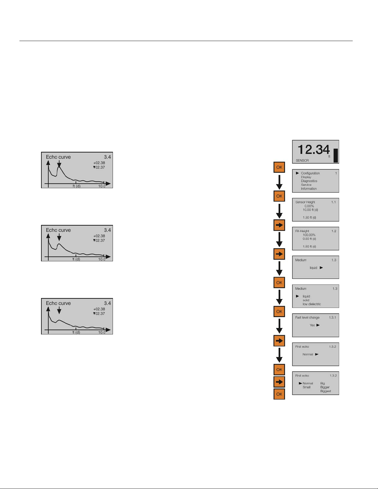
Troubleshooting (continued) Step Eight
FIRST ECHO ADJUSTMENT
This function increases or decreases the peak strength of the sensor’s First Echo return, and should only be
performed if: 1) The liquid has a very high dielectric constant value and primarily stays in the near full range of
the tank, resulting in a very high First Echo peak strength or; 2) Process conditions, such as when the liquid has
a very low dielectric constant value, or when obstructions, heavy foam or turbulence exist in the tank, resulting
in little or no First Echo peak strength. Note: Under condition one (Example 1), it can be beneficial to decrease
the First Echo peak strength. Under condition two (Example 3), it can be beneficial to increase the First Echo
peak strength.
Example 1
First Echo peak is very strong
and can be reduced.
Example 2
First Echo peak is normal and
no adjustment is required.
Example 3
First Echo peak is weak and can
be increased.
1) From the Main Screen, press OK to
advance into the Main Menu.
2) Press OK to advance into the
Configuration Menu.
3) Press Right Arrow to move from Empty
Configuration to Full Configuration.
4) Press Right Arrow to move from Full
Configuration to Medium.
5) Press OK to advance into Medium and
Liquid, Solid & Low Dielectric will
appear.
6) Press OK to advance into Liquid and
Fast Level Change will appear.
7) Press Right Arrow to move from Fast
Level Change to First Echo.
8) Press OK to advance into First Echo.
9) Press Right Arrow to change the First
Echo setting.
10) When setting is correct, press OK to
save.
First Echo
Adjustments
Normal - No adjustment
Small - Decrease by 10 dB
Big - Increase by 10 db
11) When done, press ESC to return to
Medium, press ESC again to return to
the Configuration Menu, and press ESC
a third time to return to the Main Screen.
Bigger - Increase by 20 db
Biggest - Increase by 40 db
| 72 MN301900 Rev B
Page 73
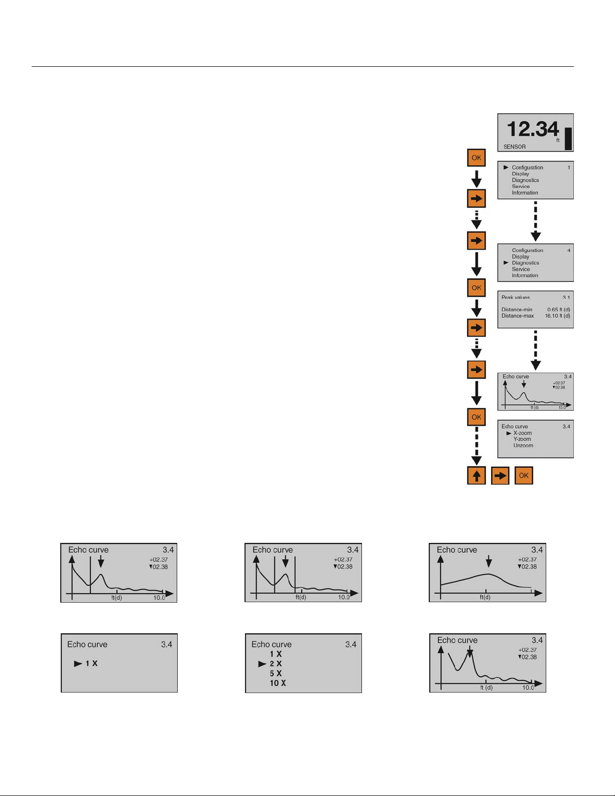
Troubleshooting (continued) Step Eight
ECHO CURVE ZOOM
This function zooms in and magnifies an Echo Curve over a specified range.
1) From the Main Screen, press OK to advance into the Main Menu.
2) Press Right Arrow repeatedly until the arrow is next to Diagnostics.
3) Press OK to advance into Diagnostics.
4) Press Right Arrow repeatedly until Echo Curve appears.
5) Press OK to advance into Echo Curve.
6) Use the Right Arrow to scroll among the three settings (X-zoom, Y-zoom,
Unzoom).
7) Press OK to select X-zoom.
8) Press OK to advance into the first X-zoom boundary (Example 1). Press Right
Arrow to move the boundary to its desired location. Press OK to set the boundary
and a second X-zoom boundary will appear.
9) Press Right Arrow to move the boundary to its desired location (Example 2).
Press OK to set the boundary and the screen will show the expanded X-axis
(Example 3). Press ESC to exit.
10) Press OK to advance into Y-zoom (Example 4). Press Right Arrow to move to
the desired zoom magnification (Example 5). Press OK to set the zoom and the
screen will show the expanded Y-axis (Example 6). Note: If you wish to start
over, press ESC, return to Echo Curve, select Unzoom, and begin the procedure
again.
11) When done, press ESC to return to Echo Curve, press ESC again to return to
Diagnostics, and ESC a third time to return to the Main Screen.
X-zoom (Example 1) X-zoom (Example 2) X-zoom (Example 3)
Y-zoom (Example 4) Y-zoom (Example 5) Y-zoom (Example 6)
MN301900 Rev B 73 |
Page 74
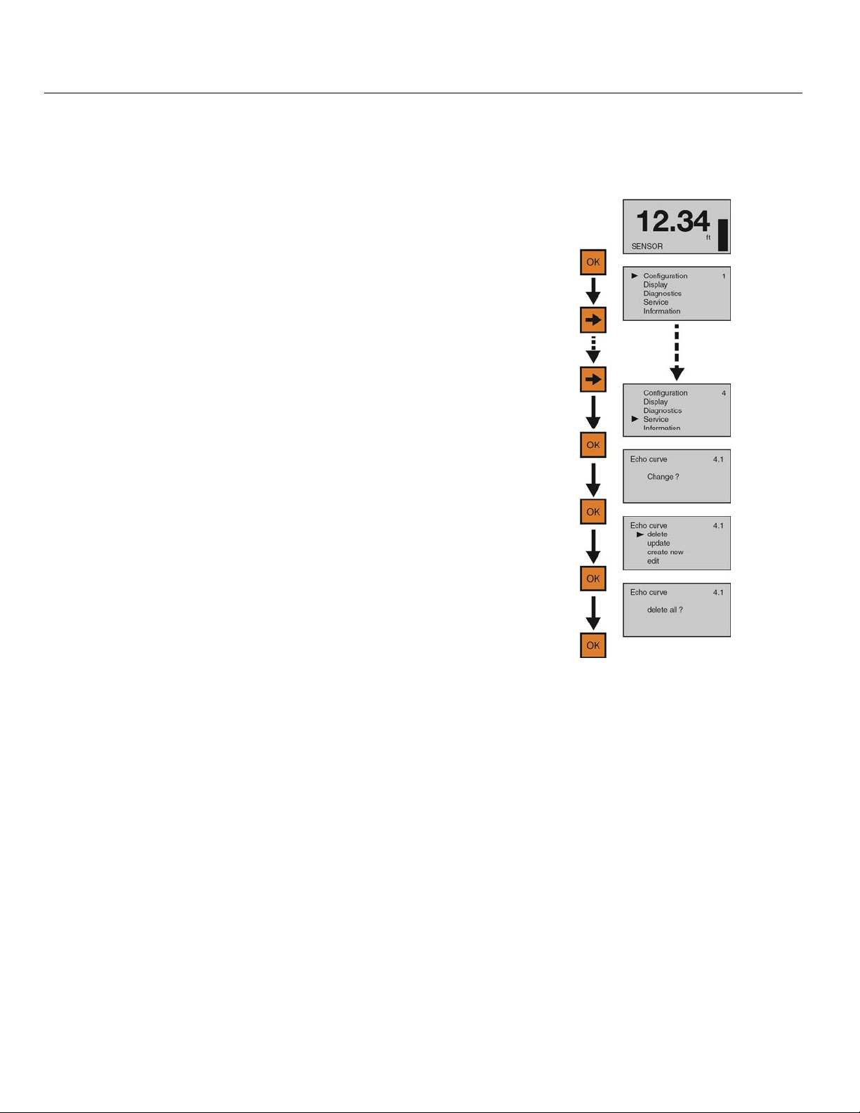
Troubleshooting (continued) Step Eight
FALSE ECHO CURVE DELETE
This function deletes a saved False Echo Curve. Note: If you are dissatisfied with the sensor’s performance
(operating with a False Echo Curve), you may delete it, and consider creating a new False Echo Curve.
1) From the Main Screen, press OK to advance into the Main
Menu.
2) Press Right Arrow repeatedly until the arrow is next to
Service.
3) Press OK to advance into Service and Echo Curve will
appear.
4) Press OK to make a change to Echo Curve.
5) Press OK to select Delete.
6) Press OK to Delete All.
7) Press ESC to return to Service and press ESC a second
time to return to the Main Screen.
| 74 MN301900 Rev B
Page 75
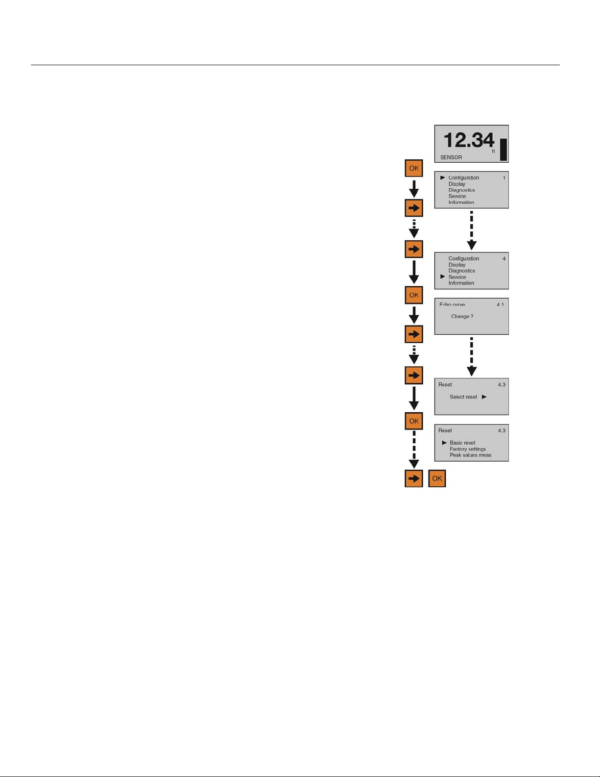
Troubleshooting (continued) Step Eight
RESET
This function resets the sensor’s configuration (basic or factory) settings and memory (peak values measured).
1) From the Main Screen, press OK to advance into the Main
Menu.
2) Press Right Arrow repeatedly until the arrow is next to
Service.
3) Press OK to advance into Service.
4) Press Right Arrow repeatedly until Reset appears.
5) Press OK to advance into Reset.
6) Use the Right Arrow to scroll among the three reset types
(Basic Reset, Factory Settings, Peak Value Meas).
a) Basic Reset
i) Resets basic configuration settings, process adjustment settings, and peak level values in
memory (retaining any advanced adjustment settings).
b) Factory Settings
i) Resets ALL settings and memory to factory default.
Note: Only perform the Factory Setting after consulting with a Flowline Representative. Make sure to record all
of your settings including the Distance Adjustment (4.9) setting before performing the Factory Reset.
c) Peak Values Measured
i) Resets the minimum and maximum peak level values in memory (retaining any basic
configuration, process adjustment and advanced adjustment settings).
7) Use OK to select the desired type of reset.
8) When done, press ESC to return to Service, and press ESC a second time to the Main Screen.
MN301900 Rev B 75 |
Page 76
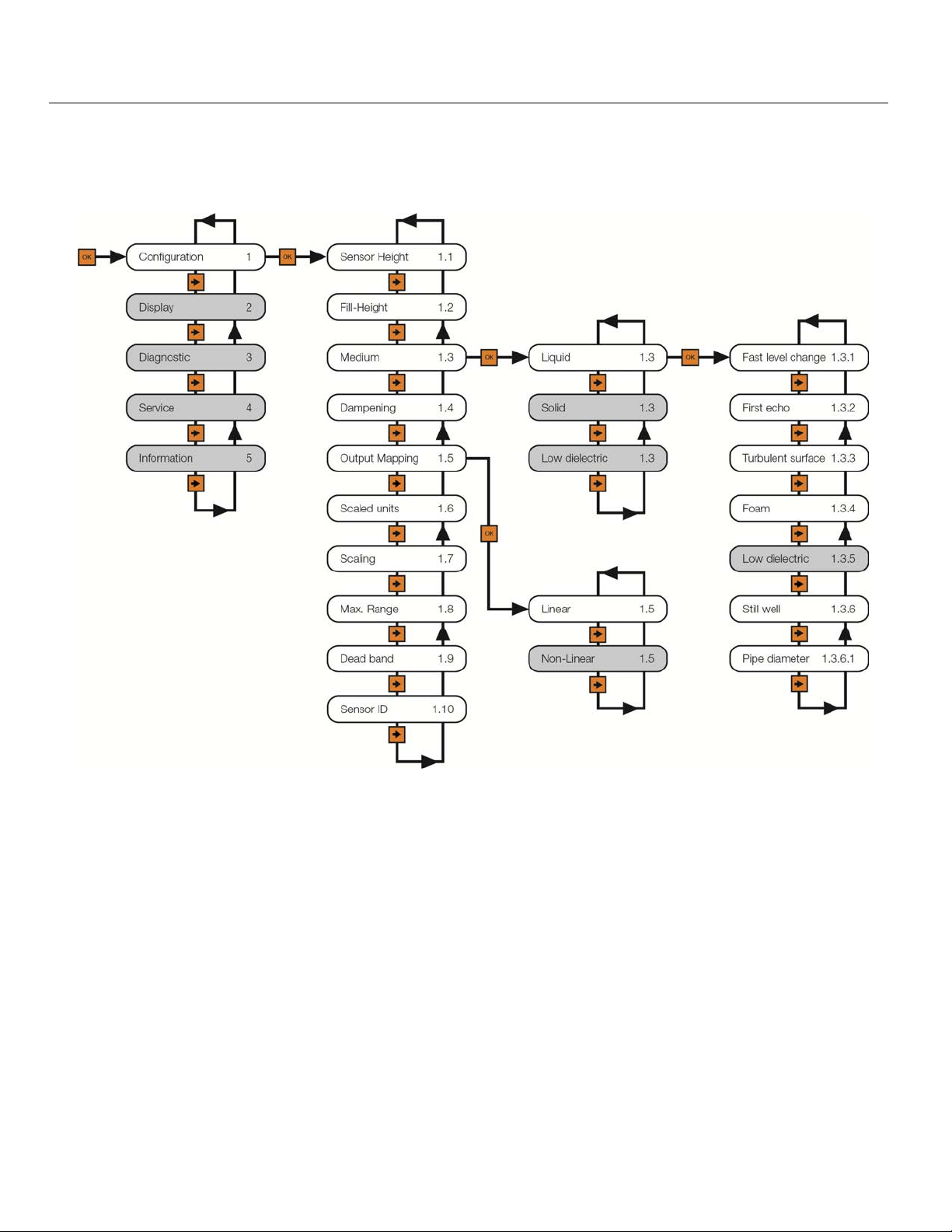
Appendix Step Nine
CONFIGURATION MENU
The basic configuration functions are found under Configuration. The below tree shows the 10 function settings
and how to navigate between them.
Note: Press ESC to back-up to the previous level.
| 76 MN301900 Rev B
Page 77
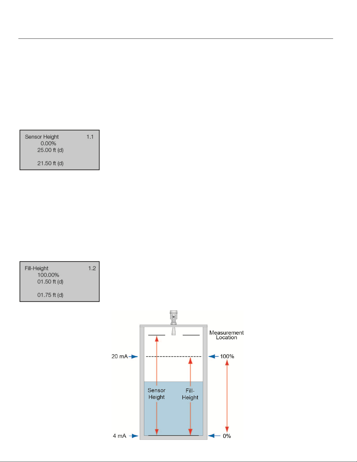
Appendix (continued) Step Nine
EMPTY CONFIGURATION
This function adjusts the empty linear scaled current output (4mA) and provides two different adjustment
methods:
The primary method involves setting the value based upon the distance from the bottom of the sensor.
This is a measured value using the units of operation for the sensor. For example, if the units of
operation are in meters, then the setting must also be in meters.
A second method involves setting a value based upon the percentage of the Range value. For
example, if the Range is set to 10ft, then a 10% setting is equivalent to 1ft of liquid height or 9ft of air
gap away from the sensor. Note: Set the Range value before setting the Empty Configuration value.
Shows the percentage of empty based upon the Range setting.
Shows the distance from the bottom of the sensor to the empty tank.
Shows the air gap distance from the liquid to the bottom of the sensor.
FULL CONFIGURATION
This function adjusts the full linear scaled current output (20mA) and provides two different adjustment
methods:
The primary method involves setting the value based upon the distance from the 0% level setting (see
below). This is a measured value using the units of operation for the sensor. For example, if the units of
operation are in meters, then the setting must also be in meters.
The second method involves setting a value based upon the percentage of the Range value. For
example, if the Range is set to 10ft, then a 95% setting is equivalent to 9.5ft of liquid height or 0.5ft or air
gap away from the sensor. Note: Set the Range value before setting the Full configuration value.
Shows the percentage of full based upon the Range setting.
Shows the distance from the bottom of the sensor to the full tank.
Shows the air gap distance from the liquid to the bottom of the sensor.
MN301900 Rev B 77 |
Page 78
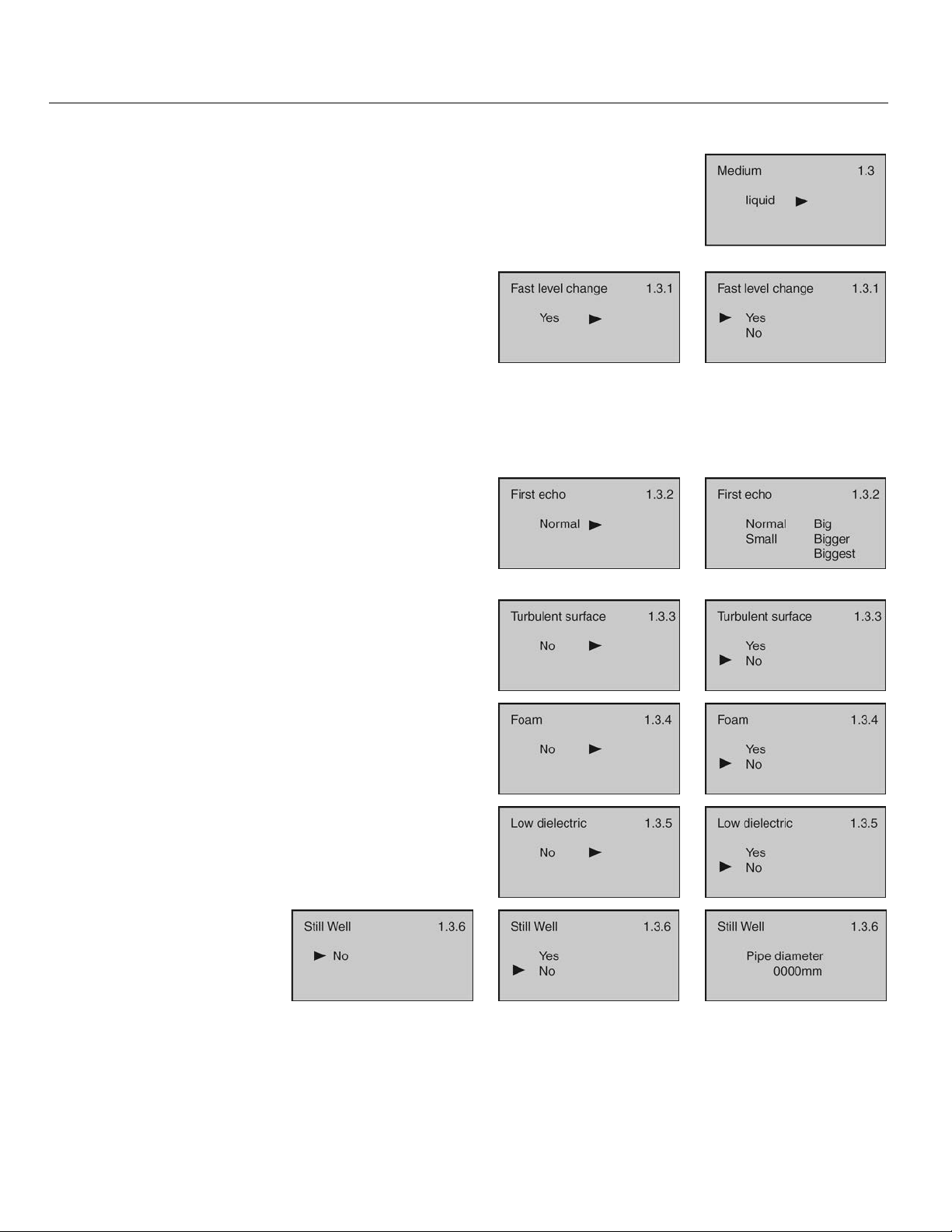
Appendix (continued) Step Nine
MEDIUM
This function identifies the type of media that the sensor is measuring including
Liquid, Solid or Low Dielectric. Each has various settings to address the different
reflective properties associated with each medium. Default is Liquid.
The Liquid Medium function has the following settings:
Fast Level Change - Used when the media’s level
rise or fall within the tank is greater than a rate of 1”
per second (25.4mm/sec). Selections are YES or
NO. Default is NO.
First Echo - Used when the sensor has difficulty
seeing the first echo return. This setting adjusts the
peak strength (dB) of the first echo. Default is
Normal. Below are the settings:
o Normal - No adjustment
o Small - Decreases by 10dB
o Big - Increases by 10dB
o Bigger - Increases by 20dB
o Biggest - Increases by 40dB
Turbulent Surface - Used when the surface of the
liquid is turbulent or agitated. Selections are YES or
NO. Default is NO.
Foam - Used when the entire liquid surface is
covered with foam. Selections are YES or NO.
Default is NO.
Low Dielectric - Used when the liquid has a low
dielectric constant (and should not be performed
without first consulting with the factory). Selections
are YES or NO. Default is NO.
Still Well - Used when
the sensor is installed in
a still well, stand pipe or
sight glass. Selections
are YES or NO.
is
NO. Note: If YES is
Default
selected, the pipe (inner)
diameter must be
entered.
| 78 MN301900 Rev B
Page 79
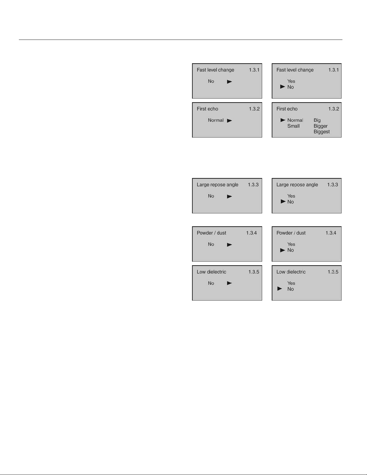
Appendix (continued) Step Nine
The Solid Medium function has the following settings (and should not be performed without first consulting with
the factory):
Fast Level Change - Used when the media’s level
rise or fall within the tank is greater than a rate of 1”
per second (25.4mm/sec). Selections are YES or
NO. Default is NO.
First Echo - Used when the sensor has difficulty
seeing the first echo return. This setting adjusts the
peak strength (dB) of the first echo. Default is
Normal. Below are the settings:
o Normal - No adjustment
o Small -Decreases by 10dB
o Big - Increases by 10dB
o Bigger - Increases by 20dB
o Biggest - Increases by 40dB
Large Repose Angle - Used when the repose angle
of the material is steep. Repose angle is the
steepest angle of assent or descent relative to the
horizontal plane that a material can be piled without
sliding. The repose angle varies between different
materials. Selections are Yes or No. Default is No.
Powder / Dust - Used when powder or dust are
present in the atmosphere above the material.
Selections are Yes or No. Default is No.
Low Dielectric - Used when the material has a low
dielectric constant (and should not be performed
without first consulting with the factory). Selections
are YES or NO. Default is NO.
MN301900 Rev B 79 |
Page 80
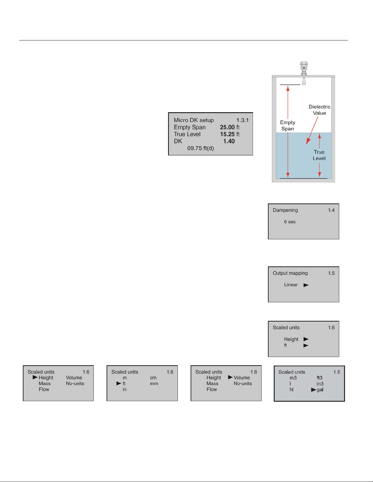
Appendix (continued) Step Nine
The Low Dielectric Medium function has the following settings (and should not be performed without first
consulting with the factory):
When the dielectric constant of the media is ≤ 4, the amplitude of the direct
echo from the media may be low and difficult to detect. However, by
measuring the echo reflected from the bottom of the tank, the liquid level can
be measured. Two parameters must be input to complete the setup: 1)
Distance from the bottom of the sensor to the tank bottom (Empty Span) and;
2) Distance from the tank bottom to the liquid level (True Level).
Empty Span - Distance from the bottom of
the sensor to the tank bottom.
True Level - Distance from the tank bottom
to the liquid level.
DK - Media dielectric constant (determined
by sensor).
Note: Once this feature has been activated, only a factory setting can undo
its activation. A factory reset will erase all active settings including Echo
Curves.
DAMPEN
This function sets the sampling rate for which the sensor updates the current
output. The value is entered in seconds. Default is 6 seconds.
Decreasing the value will make the output more responsive to level
changes.
Increasing the value will make the output less responsive to level changes.
OUTPUT MAPPING
This function sets the correlation between the measured value and the current
output. Selections are Linear or Non-Linear. Default is Linear.
Keep the setting on Linear. Note: This setting should not be changed
without first consulting with the factory.
SCALED UNITS
This function sets the type of measurement (Height, Volume, Mass, Flow or
No-Units) and units of measurement (which vary based upon the type of
measurement) displayed and input during configuration. Default is Height in
Units of feet (ft).
| 80 MN301900 Rev B
Page 81
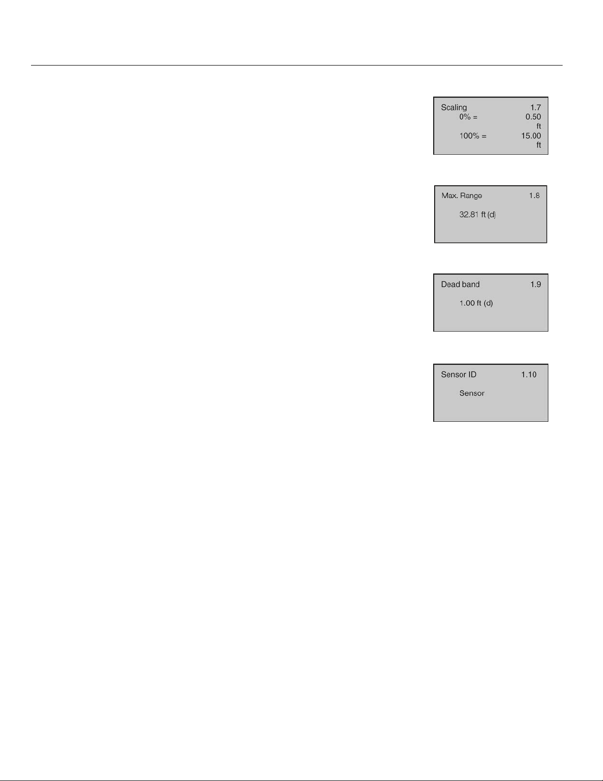
Appendix (continued) Step Nine
SCALING
This function sets the span values for 0% and 100% as an alternative method
of adjusting the Empty Configuration and Full Configuration settings.
Defaults are 0% and 100%.
RANGE
This function sets the maximum range that the sensor can measure which is
typically the distance from the bottom of the sensor to the empty tank bottom.
Default is the maximum range of the sensor.
DEAD BAND
This function sets the dead band or the minimum distance that the sensor will
measure. Default is 12” (30cm). Minimum setting is 2” from the bottom of
the antenna. Consult factory when setting the dead band less than the factory
setting.
SENSOR ID
This function sets an 11-digit identification code. The setting can use
alphanumeric values from A to Z and 0 to 9. Default is the sensor’s 4-digit
Series number.
MN301900 Rev B 81 |
Page 82
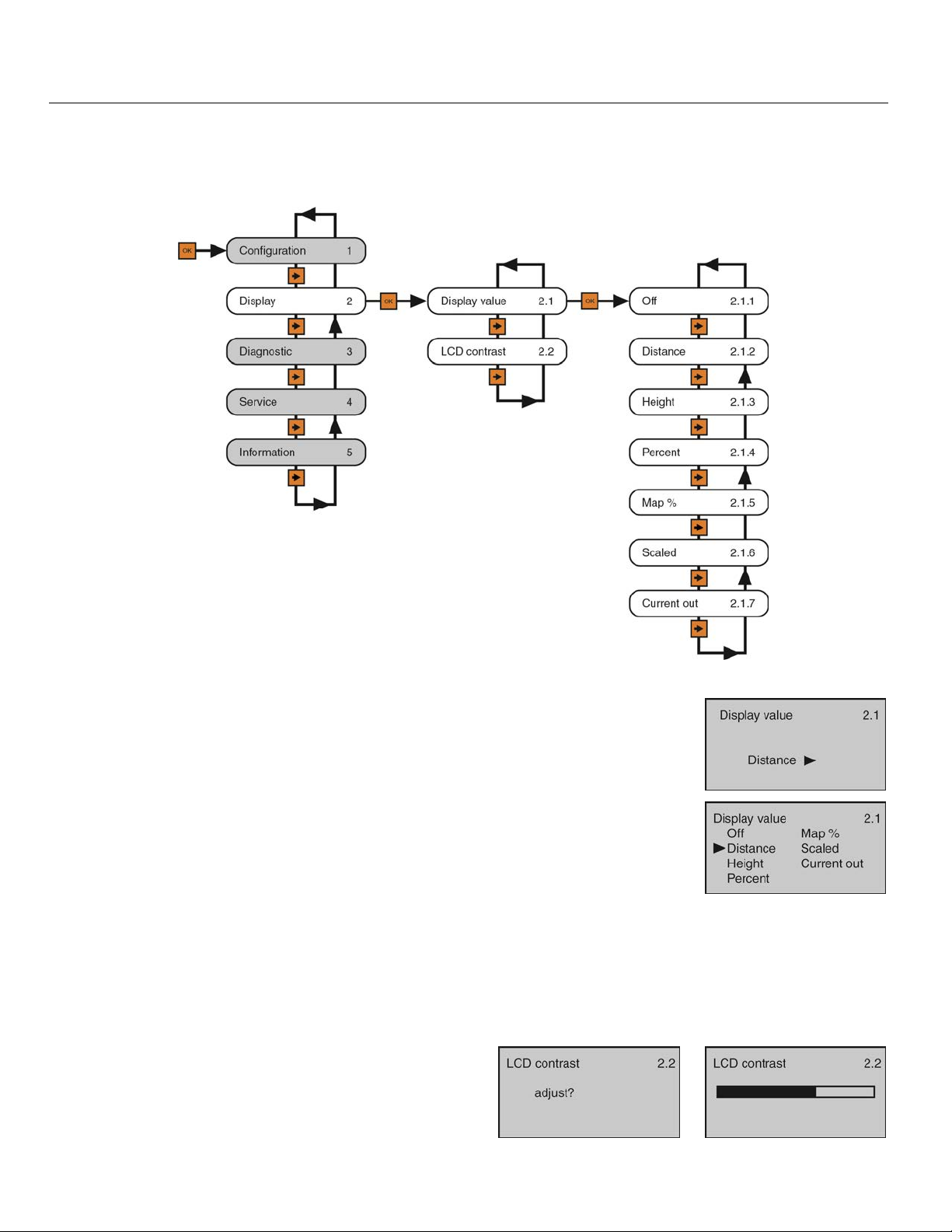
Appendix (continued) Step Nine
DISPLAY MENU
This menu sets the Display Value and LCD Contrast. The below tree shows the 2 function settings and how
to navigate between them.
DISPLAY VALUE
This function sets the Display Value. Default is (air gap) Distance. Below are
the settings:
OFF - Turns the display OFF.
Distance - Displays the distance from the bottom of the sensor to the liquid
surface.
Height - Displays the height of media in the tank from the Maximum Range
Setting.
Percent Span - Displays the level based on its percentage of operational span.
Map Percentage - Displays the level based on its percentage of operational
range.
Scaled - Displays the level based on a scaled value between 0 (empty) and 10
(full).
Current Output - Displays the 4-20 mA current output.
LCD CONTRAST
This function sets the B/W display contrast. Press the
Up Arrow to increase the contrast, and press the Right
Arrow to decrease the contrast.
| 82 MN301900 Rev B
Page 83
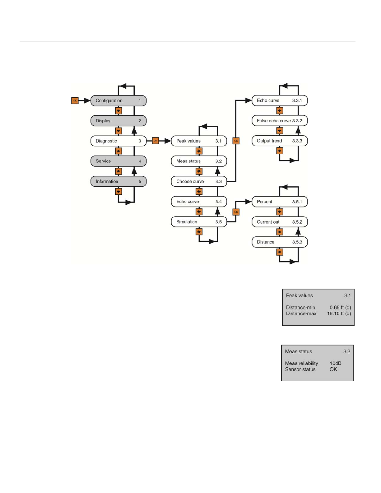
Appendix (continued) Step Nine
DIAGNOSTICS MENU
This menu provides information about the operational status of the sensor and diagnostic tools. The below tree
shows the 5 function settings and how to navigate between them.
PEAK VALUES
This function displays the lowest and highest level height distances (d) that the
sensor has measured during operation. To reset these values, use the Reset >>
Peak Measured Values option found under the Service Menu.
MEASUREMENT STATUS
This function displays the signal strength (dB) of the echo returns (Measurement
Reliability) and the operational status of the sensor (Sensor Status). A signal
strength of 10dB or higher is acceptable. Anything under 10dB is considered a
weak signal. The cause of a weak signal is often obstructions within the beam path
or a poor installation.
Sensor status confirms whether the sensor is operating as expected. If normal, the
descriptor will be OK. If abnormal, the descriptor will be one of the following error
codes:
E11 – Insufficient power E12 – Sensor open circuitE14 – Weak return echo E15 – ROM
error E17 – ROM error
MN301900 Rev B 83 |
Page 84
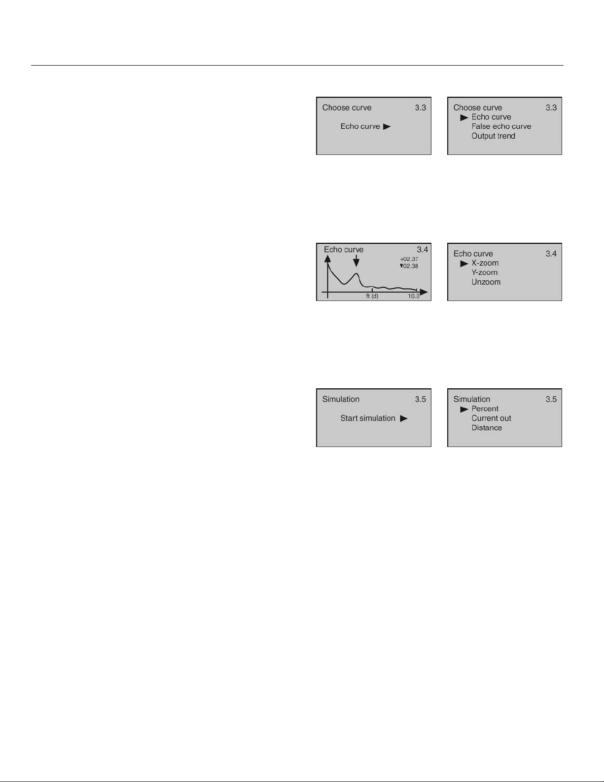
Appendix (continued) Step Nine
CHOOSE CURVE
This function sets which information is displayed.
Default is Echo Curve.
Echo Curve - Shows the echo return energy received
by the sensor over distance.
False Echo Curve - Shows the false echo returns
which are mapped out (not considered) by the sensor.
Output Trend - Shows recent history of where the past
level readings have occurred.
ECHO CURVE
This function shows the Echo Curve and allows the user
to zoom in and magnify information along the X-axis
and Y-axis.
X-zoom - Expands echo information along the X-axis.
Used to determine the location of an echo.
Y-zoom - Expands echo information along the y-axis.
Used to determine the energy of an echo.
Unzoom - Returns the display to the original setting.
SIMULATION
This function sets a fixed 4-20mA current output from
the sensor for purposes of testing devices receiving
information from the sensor. The simulated current
output may be set with the below three input methods:
Percent - This method uses percentage of span (0-
100%) to set the current output (4-20mA) between the
Empty and Full Configuration values with 100% equal
to 20 mA and 0% equal to 4mA.
Current Out - This method directly sets the current
output (4-20mA) to the desired value.
Distance - This method uses distance from the
sensor’s measurement location to set the current
output (4-20mA) between the Empty and Full
Configuration values.
| 84 MN301900 Rev B
Page 85
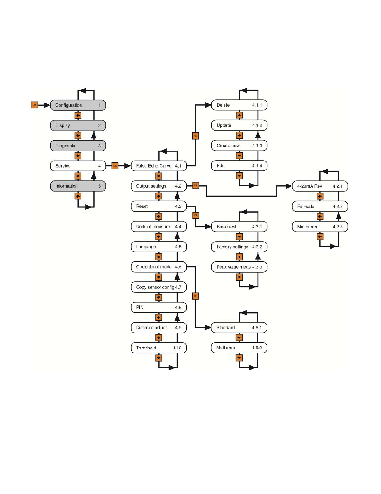
Appendix (continued) Step Nine
SERVICE MENU
This menu is used to make more advanced adjustments to the sensor. Note: Some of these functions should
only be performed by a trained technician.
MN301900 Rev B 85 |
Page 86
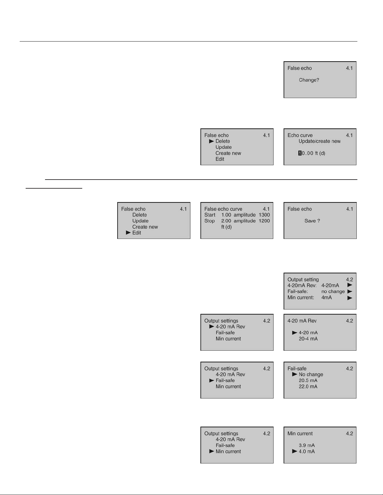
Appendix (continued) Step Nine
FALSE ECHO
Obstructions in the tank (mixer blades, side wall weld joints or material build-up,
submersible pumps, piping, other apparatus) or tall tank risers or installation fittings
can create false echo returns that impair the sensor’s measurement. This function
maps all echo returns within the tank, differentiating between good and false echoes,
and stores those identified as false into the False Echo Curve, so they will not be considered in the level
measurement. Note: A False Echo Curve should only be performed when the tank is empty so that all false
reflections will be detected.
This function allows the selection of the below False
Echo Curve settings:
Delete - Used to remove a stored False Echo Curve.
Update - Used to update a stored False Echo Curve.
Note: Do not use this function to update an existing False Echo Curve when the level is above the original
False Echo Curve.
Create New - Used to create a new False Echo Curve.
Edit - Used to edit the false
echoes stored in a False
Echo Curve. Note: This
function should only be
performed by a trained
technician.
OUTPUT SETTINGS
This function allows the selection of the below of 4-20mA Reverse, Fail-Safe and
Minimum Current output settings. The initial screen indicates the status of the three
functions.
4-20 mA Reverse - Used to set the current output at 4-
20 mA or 20-4 mA. Selecting 4-20 mA sets the output
with 4mA @ bottom and 20mA @ top of the tank.
Selecting 20-4 mA sets the output with 20mA @ bottom
and 4mA @ top of the tank. Default is 4-20mA.
Fail-Safe – Used to set the current output to a
designated if the sensor loses measurement
confidence. Selecting No Change will hold the current
at its last valid current output. Selecting 20.5mA will
force the current to jump to 20.5mA. Selecting 22.5
mA will force the current to jump to 22.5 mA. Default
is 22.0mA.
Minimum Current - Used to set the minimum current
output at either 4.0mA or 3.9mA. Default is 4.0mA.
| 86 MN301900 Rev B
Page 87
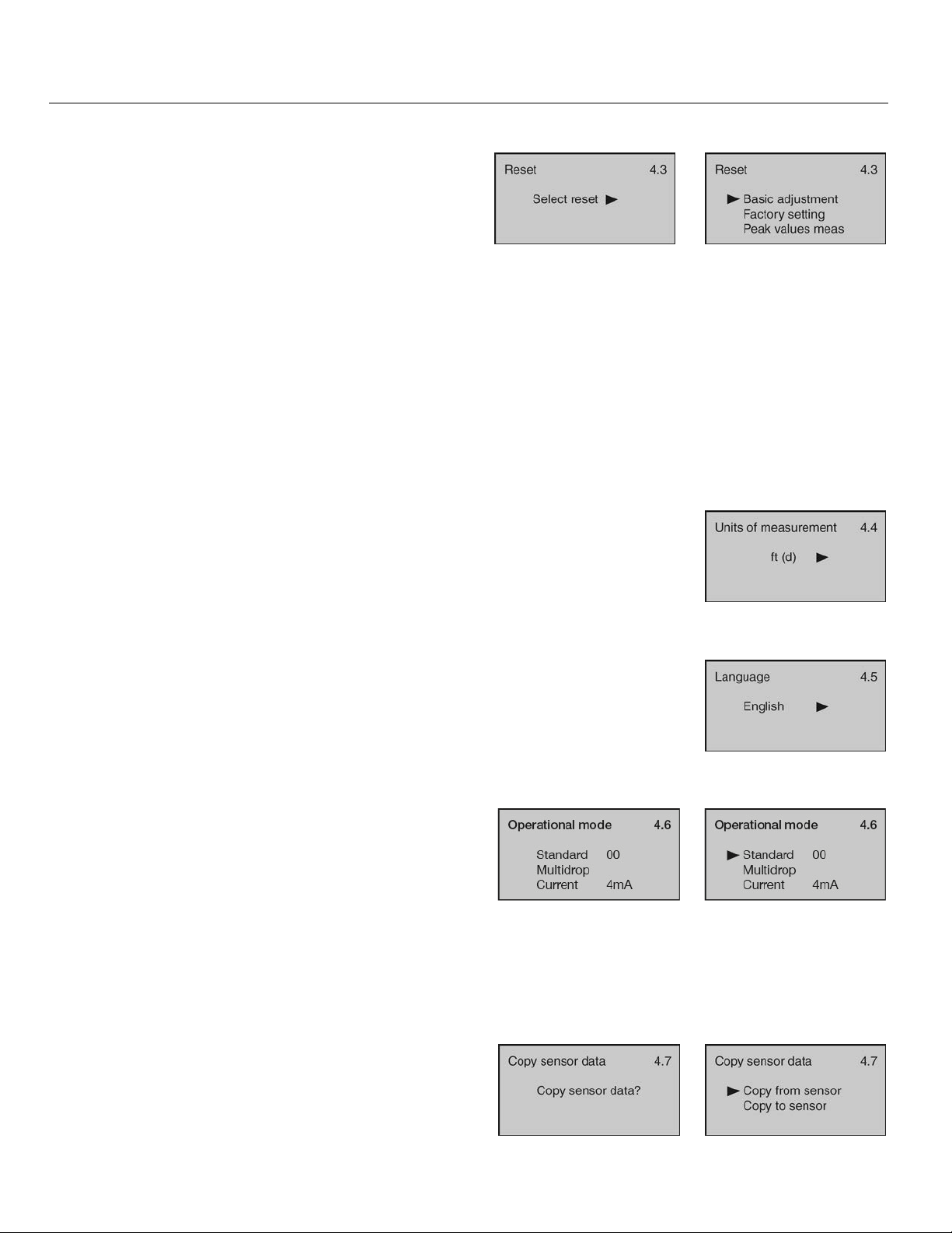
Appendix (continued) Step Nine
RESET
This function allows the configuration (basic or factory)
settings and memory (peak values measured) to be
reset. Below are the three reset types:
Basic Reset – Used to reset the basic configuration
settings, process adjustment settings, and peak level
values in memory (retaining any advanced adjustment
settings).
Factory Settings – Used to reset ALL settings and memory to factory default.
Note: Only perform the Factory Setting after consulting with a Flowline Representative. Make sure to record all
of your settings including the Distance Adjustment (4.9) setting before performing the Factory Reset.
Peak Values Measured – Used to reset the minimum and maximum peak level values in memory (retaining
any basic configuration, process adjustment and advanced adjustment settings).
UNITS OF MEASUREMENT
This function allows the units of measurement to be changed between Metric and
English system units.
LANGUAGE
This function sets the display language. Default is English.
HART® OPERATIONAL MODE
This function allows for the sensor’s HART® address to
be changed from the Standard mode with an address of
0 to a Multidrop mode where the address can be set
from 1 to 15. Default is Address 0. Note: This function
should only be performed by a trained technician.
This function allows for the loop consumption (constant
current draw) to be set to either 4mA or 8mA. Default
is 4mA.
COPY SENSOR DATA
This function allows configuration and memory data to
be uploaded to or downloaded from the sensor. Note:
This function should only be performed by a trained
technician.
MN301900 Rev B 87 |
Page 88
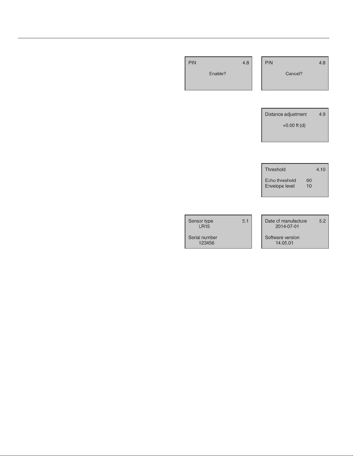
Appendix (continued) Step Nine
PIN
This function allows the sensor configuration to be
locked via a preset PIN. Note: This function should only
be performed by a trained technician.
DISTANCE ADJUSTMENT
This function allows the factory set distance of a measured value to be adjusted.
Note: This function should only be performed by a trained technician. Never
change this setting unless instructed by a Flowline representative. Be sure to
record this setting if a Factory reset is performed.
THRESHOLD
This function allows the factory set echo threshold to be adjusted. Note: This
function should only be performed by a trained technician.
INFORMATION
This function displays basic information about your
sensor including sensor type, serial number, date of
manufacture and software version.
| 88 MN301900 Rev B
Page 89
Appendix (continued) Step Nine
FACTORY SETTINGS
Below are the Empty Configuration and Full Configuration factory settings for each sensor.
Series
LR11 32.81’ (10m) 1.64’ (0.5m)
LR16 98.42’ (30m) 1.64’ (0.5m)
LR21 65.61’ (20m) 1.64’ (0.5m)
LR26 114.83’ (35m) 1.64’ (0.5m)
LR31 94.82’ (30m) 1.64’ (0.5m)
USER CONFIGURATION
Fill out the below chart and keep a record of your sensor configuration.
Empty Configuration
(4mA)
Full Configuration
(20mA)
Configuration
Units of Measurement: Feet Meters
Empty Configuration: Full Configuration:
Range (Maximum): Dead Band:
Process / Advanced Adjustments
Foam: No Yes Agitated Surface: No Yes
Fast Level Change: No Yes Low Dielectric: No Yes
Still Well: No Yes Diameter:
Dampening Time: ____________
First Echo: Normal Small Big Bigger Biggest
MN301900 Rev B 89 |
Page 90

Appendix (continued) Step Nine
TROUBLESHOOTING
Subject Comment
Display Shows E14: Sensor is in a Fail-Safe state. The return sound pulses are not
reaching the transducer. First, cycle power off and on, waiting 5
seconds between the off and on states. If problem persists, check the
installation fitting against the Installation instructions in the manual.
Display is opposite of the
measured value:
Transmitter indicates a
current of 0 mA:
Transmitter jumps to a
current reading between 19
and 20 mA:
Transmitter indicates a
current over 23 mA:
Check the Display Value setting (2.1). Distance mode indicates the
distance from the liquid to the sensor. Height mode indicates the height
of liquid in the tank. Change the Display Value from Distance to Height
or vice versa to correct. This setting does not affect the 4-20mA output.
Check the wiring for an open circuit. An open circuit is the most
common issue with a 0 mA signal.
Check the installation of the transmitter. Bad installation fittings will
cause false signals near the top of the tank, which typically translates to
a signal between 19 and 20 mA. Also look for interference just below
the transmitter. If the transmitter is installed in a metal fitting, switch to
a plastic fitting.
Immediately check the wiring for a short circuit. The EchoPulse® is
current limited to 22 mA. Anything above 23 mA indicates a short
circuit.
| 90 MN301900 Rev B
Page 91

Appendix (continued) Step Nine
Page
Left
Intentionally
Blank
MN301900 Rev B 91 |
Page 92

Warranty, Returns and Limitations Step Ten
WARRANTY
Flowline warrants to the original purchaser of its products that such products will be free from defects in material
and workmanship under normal use and service in accordance with instructions furnished by Flowline for a
period of two years from the date of manufacture of such products. Flowline's obligation under this warranty is
solely and exclusively limited to the repair or replacement, at Flowline's option, of the products or components,
which Flowline's examination determines to its satisfaction to be defective in material or workmanship within the
warranty period. Flowline must be notified pursuant to the instructions below of any claim under this warranty
within thirty (30) days of any claimed lack of conformity of the product. Any product repaired under this warranty
will be warranted only for the remainder of the original warranty period. Any product provided as a replacement
under this warranty will be warranted for the full two years from the date of manufacture.
RETURNS
Products cannot be returned to Flowline without Flowline's prior authorization. To return a product that is
thought to be defective, go to www.flowline.com, and submit a customer return (MRA) request form and follow
the instructions therein. All warranty and non-warranty product returns to Flowline must be shipped prepaid and
insured. Flowline will not be responsible for any products lost or damaged in shipment.
LIMITATIONS
This warranty does not apply to products which: 1) are beyond the warranty period or are products for which the
original purchaser does not follow the warranty procedures outlined above; 2) have been subjected to electrical,
mechanical or chemical damage due to improper, accidental or negligent use; 3) have been modified or altered;
4) anyone other than service personnel authorized by Flowline have attempted to repair; 5) have been involved
in accidents or natural disasters; or 6) are damaged during return shipment to Flowline. Flowline reserves the
right to unilaterally waive this warranty and dispose of any product returned to Flowline where: 1) there is
evidence of a potentially hazardous material present with the product; or 2) the product has remained
unclaimed at Flowline for more than 30 days after Flowline has dutifully requested disposition. This warranty
contains the sole express warranty made by Flowline in connection with its products. ALL IMPLIED
WARRANTIES, INCLUDING WITHOUT LIMITATION, THE WARRANTIES OF MERCHANTABILITY AND
FITNESS FOR A PARTICULAR PURPOSE, ARE EXPRESSLY DISCLAIMED. The remedies of repair or
replacement as stated above are the exclusive remedies for the breach of this warranty. IN NO EVENT SHALL
FLOWLINE BE LIABLE FOR ANY INCIDENTAL OR CONSEQUENTIAL DAMAGES OF ANY KIND
INCLUDING PERSONAL OR REAL PROPERTY OR FOR INJURY TO ANY PERSON. THIS WARRANTY
CONSTITUTES THE FINAL, COMPLETE AND EXCLUSIVE STATEMENT OF WARRANTY TERMS AND NO
PERSON IS AUTHORIZED TO MAKE ANY OTHER WARRANTIES OR REPRESENTATIONS ON BEHALF
OF FLOWLINE. This warranty will be interpreted pursuant to the laws of the State of California. If any portion of
this warranty is held to be invalid or unenforceable for any reason, such finding will not invalidate any other
provision of this warranty.
For complete product documentation, video training, and technical support, go to www.flowline.com.
For phone support, call 562-598-3015 from 8am to 5pm PST, Mon - Fri.
(Please make sure you have the Part and Serial number available.)
| 92 MN301900 Rev B
 Loading...