

Page 1
omega.com
e-mail: [email protected]
For latest product manuals:
omegamanual.info
User’s Guide
LMF-A550/120,
LMF-A550/240,
LMF-3550/120,
and LMF-3550/240
Benchtop Muffler Furnace
MADE IN
Shop online at
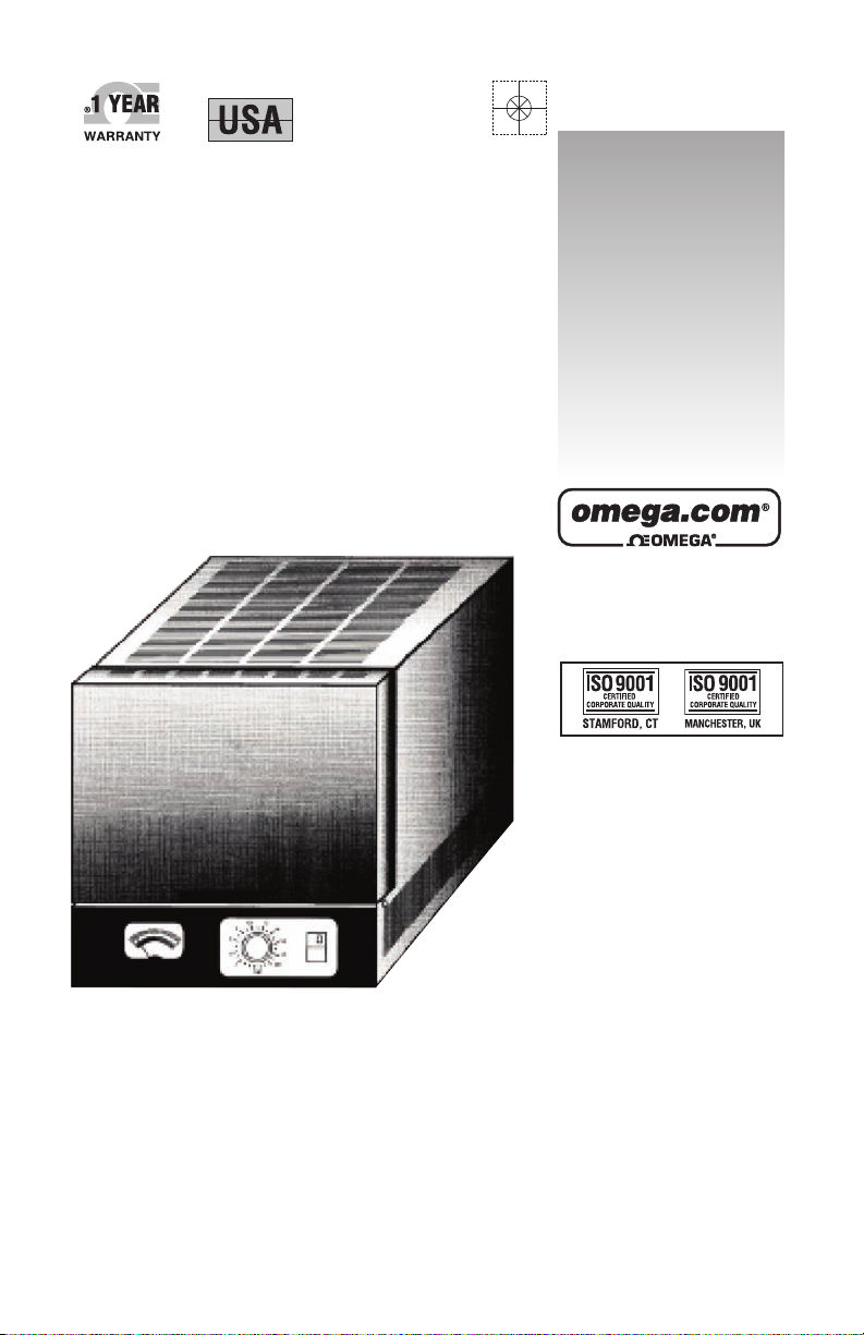
LMF-A550 SHOWN
Page 2

Servicing North America:
U.S.A.: Omega Engineering, Inc., One Omega Drive, P.O. Box 4047
ISO 9001 Certified
Stamford, CT 06907-0047
Toll-Free: 1-800-826-6342 Tel: (203) 359-1660
FAX: (203) 359-7700 e-mail: [email protected]
Canada: 976 Bergar
Laval (Quebec), H7L 5A1 Canada
Toll-Free: 1-800-826-6342 TEL: (514) 856-6928
FAX: (514) 856-6886 e-mail: [email protected]
For immediate technical or application assistance:
U.S.A. and Canada: Sales Service: 1-800-826-6342/1-800-TC-OMEGA
®
Customer Service: 1-800-622-2378/1-800-622-BEST
®
Engineering Service: 1-800-872-9436/1-800-USA-WHEN
®
Mexico En Español: 001 (203) 359-7803 FAX: 001 (203) 359-7807
Latin America [email protected] e-mail: [email protected]
Servicing Europe:
Benelux: Managed by the United Kingdom Office
Czech Republic: Frystatska 184
733 01 Karviná, Czech Republic
Toll-Free: 0800-1-66342 TEL: +420-59-6311899
FAX: +420-59-6311114 e-mail: [email protected]
France: Managed by the United Kingdom Office
Toll-Free: 0800 466 342 TEL: +33 (0) 161 37 29 00
FAX: +33 (0) 130 57 54 27 e-mail: [email protected]
Germany/Austria: Daimlerstrasse 26
D-75392 Deckenpfronn, Germany
Toll-Free: 0800 6397678 TEL: +49 (0) 7056 9398-0
FAX: +49 (0) 7056 9398-29 e-mail: [email protected]
United Kingdom: OMEGA Engineering Ltd.
ISO 9001 Certified
One Omega Drive, River Bend Technology Centre, Northbank
Irlam, Manchester M44 5BD United Kingdom
Toll-Free: 0800-488-488 TEL: +44 (0) 161 777-6611
FAX: +44 (0) 161 777-6622 e-mail: [email protected]
OMEGAnet®Online Service Internet e-mail
omega.com [email protected]
It is the policy of OMEGA Engineering, Inc. to comply with all worldwide safety and EMC/EMI
regulations that apply. OMEGA is constantly pursuing certification of its products to the European New
Approach Directives. OMEGA will add the CE mark to every appropriate device upon certification.
The information contained in this document is believed to be correct, but OMEGA accepts no liability for any
errors it contains, and reserves the right to alter specifications without notice.
WARNING: These products are not designed for use in, and should not be used for, human applications.
Page 3
Unpacking Instructions
Remove the Packing List and verify that you have received all equipment,
including the following (quantities in parentheses):
If you have nay questions about the shipment, please call OMEGA Customer
Service Department.
When you receive the shipment, inspect the container and equipment for signs of
damage. Note any evidence of rough handling in transit. Immediately report any
damage to the shipping agent.
LMF-A550 or LMF-3550 Benchtop Muffle Furnace (1)
Ceramic Floor Tray (1)
Exhaust Port Plugs (2)
Power Cord (1)
Operator’s Manual (1)
NOTE
The carrier will not honor damage claims unless all shipping
material is saved for inspection. After examining and removing
contents, save packing material and carton in the event
reshipment is necessary.
i
Page 4
TABLE OF
CONTENTS
Section 1 Introduction..................................................................................1 - 1
1.1 General Description ...........................................................1 - 1
1.2 LMF-A550 Series Furnace Description..............................1 - 1
1.3 Features.............................................................................1 - 1
1.4 Available Models ................................................................1 - 2
Section Installing the Furnace.....................................................................2 - 1
Section 3 Operating the Furnace ................................................................3 - 1
3.1 Safety Considerations ........................................................3 - 1
3.2 Starting Operations............................................................3 - 2
Section 4 Setup and Maintenance ..............................................................4 - 1
4.1 Temperature Adjustment ....................................................4 - 1
4.2 Cleaning.............................................................................4 - 1
4.3 Fuses .................................................................................4 - 1
LMF-550 Series
Benchtop Muffle Furnace
Section 5 Troubleshooting...........................................................................5 - 1
Section 6 Accessories..................................................................................6 - 1
Section 7 Specifications ..............................................................................7 - 1
ii
Page 5
LMF-550 Series
Benchtop Muffle Furnace
Section 8 Introduction..................................................................................8 - 1
8.1 General Description ...........................................................8 - 1
8.2 LMF-3550 Series Furnace Description ..............................8 - 1
8.3 Features.............................................................................8 - 1
8.4 Available Models ................................................................8 - 2
Section 9 Installing the Furnace..................................................................9 - 1
Section 10 Operating the Furnace ............................................................10 - 1
10.1 Safety Considerations ......................................................10 - 1
10.2 Running a Program ..........................................................10 - 2
10.3 Stopping a Program .........................................................10 - 3
10.4 Programming....................................................................10 - 4
10.4.1 Ramp Rates (R) ...............................................................10 - 5
10.4.2 Temperatures (T)..............................................................10 - 5
10.4.3 Hold Times (H) .................................................................10 - 5
10.4.4 Program 0 ........................................................................10 - 6
10.5 Special Features ..............................................................10 - 6
10.5.1 Delay Start (D) .................................................................10 - 6
10.5.2 Linking Programs .............................................................10 - 8
TABLE OF
CONTENTS
Section 11 Setup & Maintenance ..............................................................11 - 1
11.1 Setup................................................................................11 - 1
11.2 Temperature Adjustment/Calibration................................11 - 2
11.3 Cleaning ...........................................................................11 - 3
11.4 Fuses ...............................................................................11 - 3
Section 12 Troubleshooting.......................................................................12 - 1
Section 13 Accessories..............................................................................13 - 1
Section 14 Specifications ..........................................................................14 - 1
iii
Page 6
TABLE OF
CONTENTS
LMF-550 & LMF3550 Series
Benchtop Muffle Furnace
Notes
iv
Page 7
LMF-A550 Series
1
Introduction
This manual is in two parts - the first half covers
the LMF-A550
covers the LMF-3550
1.1 General Description
LMF Series Benchtop Muffle Furnaces feature a 550 cubic inch
chamber with fiber insulation and firebrick heating plates.The furnace
cabinet is constructed of 16 gauge steel with a backed epoxy finish. A
atop exhaust port allows gases to be vented or may be plugged during
operation to seal the opening. Two temperature controller models are
available: automatic and multi-stage programmable. LMF series
furnaces are ideal for hear treating applications, material research and
sample ashing determinations in the geological, metallurgical, and
wastewater treatment industries. These furnaces are also used in
chemistry, physics, and engineering laboratories.
1.2 LMF-A550 Series Furnace Description
Series Furnaces. The second half
Series Furnaces.
The Model LMF-A550 furnace has an analog pyrometer which displays
temperature, scaled in 50˚ increments. Temperature is adjusted via a
large control dial, scaled in 100˚ increments. The controller repeatability
is excellent.
1.3 Features
• High performance/hybrid muffle
• Longer life and more durable than Fiber
• Faster heating, and faster cooling than Firebrick
• Wide operating temperature range 200˚C (392˚F) to 1100˚C (2012˚F)
• Smooth, low force vertical lift door, with roll back action which gives
maximum access with minium vertical space
• Durable stainless steel front panel
1 - 1
Page 8

1
Introduction LMF-A550 Series
• Automatic temperature controller; select temperature with front panel
control knob and muffle temperature is maintained at that temperature
• Easy to operate; power switch and temperature set knob
• Integrated door safety switch breaks both sides of the power line to the
muffle
• Designed for Safety Agency Approvals, (CSA & TÜV Pending)
• Individual muffle eating plate replacement
• One plate service all voltages
1.4 Available Models
Part Number Volts Controller Type
LMF-A550/120 100-125 Analog
LMF-A550/240 200-250 Analog
1 - 2
Page 9

2
LMF-A550 Series
Installing the Furnace
1. Remove all packing material from in and around the furnace.
The furnace should be located at least 15 cm (6”) away form
walls, shelves and heat sensitive materials. Open the furnace
door and remove the packing material from inside the furnace.
NOTE
The furnace front panel may show some discoloration
around the muffle due to the calibration and burn-in cycles
performed at the factory.
2. The furnace should not
other airflow restrictions.
3. On high voltage (200-250 volt) units, connect the power cord
packaged in the rear of the furnace to the socket in rear of
furnace.
4. For positioning the furnace:
a. (Combustion, Burnout or Reaction Processes) Position the
furnace under a vent hook or connect the exhaust port to a
ventilation system to prevent exposure to the exhaust
fumers. The furnace exhaust port 258 mm (1”) OD by 25
mm (1”) long can be ducted into the exhaust hood for more
effective ventilation. Stainless Steel flexible metal tubing
can be used for this ducting.
be located directly under shelves and
b. (Heat Treating or Non-Reaction Processes) Position the
furnace under a vent hood. Plug the exhaust port with the
ball plugs provided in the furnace accessory kit. This will
reduce heat loss and electricity requirements.
5. Connect the furnace to a power circuit or receptacle with an
overcurrent protection (circuit breaker or fuse) rating of 20
Amps on the low voltage model and 10 Amps on the high
voltage model. The furnace should be the only load on this
circuit.
6. Turn on the furnace lighted green power switch (at the right
side of the control panel.)
2 - 1
Page 10
2
Installing the Furnace LMF-A550 Series
7. When the door is fully closed, the power switch light should be
8. At this time, your new furnace should be set up to operate.
illuminated. As the door opens, the power switch light should
turn off. Do not attempt to operate the furnace if this light
does not turn off when the door is open.
Review the Operations Section of the manual before
proceeding to operate the furnace
2 - 2
Page 11
LMF-A550 Series
3
Operating the Furnace
3.1 Safety Considerations
- Never operate the furnace in close proximity to combustible materials
or place materials on top of the furnace.
- The furnace must be electrically grounded to a three-wire electrical
outlet or receptacle. The electrical service provided must be dedicated
line of the proper size according to local electrical codes.
- Disconnect the line cord before attempting to service the furnace.
- Do not operate the furnace controls with tongs or other tools; the tongs
will damage the control switches.
- Do not use solvents or liquid cleaners on the control panel; they will
enter the panel and damage it.
- Do not place firing trays or other hot objects directly in front of the
furnace; they will melt the graphic overlay.
- Always verify that the power switch light is off before attempting to load
or reach into the furnace chamber with any tools or instruments.
- As a routine working precaution, always wear safety glasses and
protective gloves when operating, loading and unloading the furnace.
OSHA AND CALIFORNIA PROPOSITION 65:
MUFFLE DUST EXPOSURE
In keeping with the policy of OMEGA Engineering to build safe products,
comply with all National and State statutes and keep you, the valued
customer informed; the services of a Certified Industrial Hygienist firm
were employed to test and evaluate the lab operator’s exposure to
respirable refractory ceramic fiber (RCF) and crystobalite (a for of
crystalline silica) present tin the furnace muffle.
The findings of this test revealed that levels of exposure during the
normal operation of this equipment, as outlined in the Operator’s
Manual, were far less than the Permissible Exposure Limit set by the
Federal Government.
3 - 1
Page 12
3
Operating the Furnace LMF-A550 Series
When it becomes necessary to replace the muffle, the person doing this
work is recommended to wear HEPA filter respirator and protective
gloves as a precautionary matter.
Seal used muffle in a plastic bag and dispose of in accordance with
local, state and Federal regulations.
Because this product and many similar products on the market today
contain crystalline silica and ceramic fibers, it is necessary under the
statutes of California Proposition 65 that OMEGA Engineering include
the following statement:
“This product contains substance(s) known to the State of California to
cause cancer.” Material Safety Data Sheets for RCF materials supplied
upon request.
Designed to meet Canadian Standards Association (CSA), TÜV and
Underwriters Laboratories (UP) safety requirements.
3.2 Starting Operation
Close the furnace door. Turn the green power switch to the on (|)
position. The light inside the switch will turn on. An interlock door switch
located inside the furnace disconnects the power to the muffle when the
door is opened. The door must be closed for the furnace to heat.
3 - 2
Turn the setpoint know to the desired temperature and the furnace will
ramp to the set temperature. Turn off the power switch to turn off the
furnace.
The temperature rate will start out at full speed and gradually slow down
as it approaches the setpoint temperature. If a slower temperature
increase rate is required, set the temperature at serval intermediate
temperatures.This will cause the control to approach each intermediate
temperature at a slower rate.
NOTE
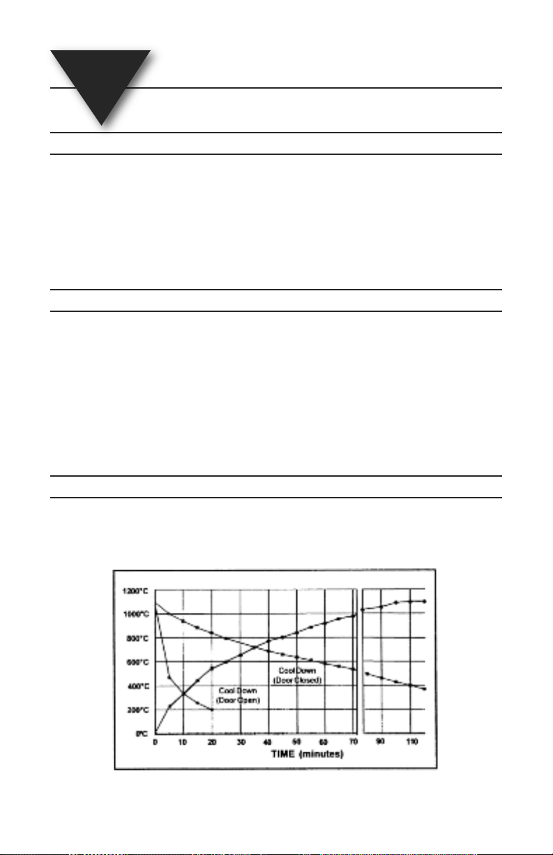
See the rate curve in Chapter 7 to determine the time
required to reach setpoint.
Page 13
LMF-A550 Series Operating the Furnace
Operating Examples:
The furnace will continuously operate a 900˚C each day.
- Insert your work, close the door, adjust the knob to 900˚C (white inside
scale).
- Turn the power switch to the on position (the green light should come
on when the door is down). IF the same temperature is needed each
day, the knob does not have to be adjusted.
- The furnace will heat to the temperature indicated on the front control
panel. Turn off the power switch when the cycle is finished.
A temperature cycles calls for a slow ramp to 700˚C (1300˚F).
Procedure:
- Insert your work and close the door.
- Turn the power switch to the on position (the green light should come
on when the door is down).
3
- Turn the setpoint knob to 300˚C (inside scale), 30 minutes later turn te
know to 500˚C, and finally 30 minutes later to 700˚C
- The furnace load slowly heats to the desired 700˚C.
NOTE
Because of the nature of the control, the first 90% of the rate
will be relatively fast while the last 10% take somewhat
longer.The furnace will reach the setpoint, but it takes some
time. If a faster rate is required, set the furnace to
approximately 10% to 20% higher than desired setpoint and
them adjust to the desired setpoint when the temperature is
reached.
3 - 3
Page 14
3
Operating the Furnace LMF-A550 Series
Notes
3 - 4
Page 15
LMF-A550 Series
4
Setup & Maintenance
4.1 Temperature Adjustment
Unplug the power cord before attempting to adjust the
calibration. The Thermocouple and PC board are connected
to the ac power supply.
Every furnace is calibrated in the factory at 1100˚C.The calibration can
be adjusted by turning the trimmer potentiometer (pot) RP1 located on
te controller board. If the meter temperature is lower than the
temperature setting that the control now is set to , turn the trimmer pot
one 1/4 turn clockwise. IF the temperature is higher than the
temperature setting that the control know is set to, turn the rimmer pot
on 1/4 turn counter-clockwise. Allow the furnace 10 to 20 minutes to
stabilize before making further adjustments.
CAUTION
4.2 Cleaning
- Vacuum dust and dirt from the furnace rather than blow. This will
minimize the amount of airborne dust particles.
- Use a sot damp cloth to clean the control panel. Avoid excess water or
solution when cleaning the furnace. These solutions can attach the
panel or electronics and cause the furnace to malfunction.
4.3 Fuses
F250V @ 20A - Fast acting, ceramic (Bussman 3AB - 20 Amp, 250V)
Symbol Table
- Alternating current
- On (Supply)
- Off (Supply)
- Hot Surface
- Protective Conductor Terminal
4 - 1
Page 16
1
Setup & Maintenance LMF-A550 Series
Notes
4 - 2
Page 17

LMF-A550 Series
5
Problem Checklist/Causes
Troubleshooting
Not Heating Does the green power switch light?
Slow Heating The control will slowly approach the setpoint
No - Check the power receptacle or
outlet for power.
- Check the door that it is
completely closed. Dor switch may
be interruption power.
Yes - Check the control knob and verify
that it is turned to the desired
temperature.
- Check the fuse on the controller
printed circuit board.
- Check the hating element plates
for continuity.
- f the muffle is hot but the meter
reads a low temperature check the
thermocouple for shorts to the
cabinet.
temperature. Set to a higher temperature and
then turn down to reduce the heat up time.
On the low voltage (100-125Vac) models, the
heating element plates are wired in parallel. If
one plate fails, the furnace will heat very slowly
and not reach the setpoint temperature.
Poor Temperature Slight changes in the knob rotation will
Accuracy have a significant impact on the setpoint
temperature. If major differences exist between
the meter and the knob scale, a temperature
adjustment can be made as described in
Section 4.1.
The door is too The amount of force or drag on the
loose or too tight door movement can be changed by adjusting
the hex screws located on te upper rear
corners of the furnace cabinet. Turning the
screw clockwise adds drag and requires more
force.
5 - 1
Page 18
5
Troubleshooting LMF-A550 Series
NotesNotesNotes
5 - 2
Page 19

LMF-A550 Series
6
Description Part Number
Tongs; 25 cm (10”) Stainless Steel 9390014
Tongs: 30 cm (12”) Stainless Steel 9390015
Tongs: 36 cm (14”) Plated Steel 9491010B
Heating Plate (1) LMF-HP
Ceramic Floor Tray LMF-CFT
Thermocouple LMF-TC
Muffle Hardening Agent 9491006
Temperature, Pellets, Bottle of 25
Exhaust port ball plug (small) 9491093A
Accessories
705˚C (1300˚F) 9490911
815˚C (1500˚F) 9490912A
6 - 1
Page 20
6
Accessories LMF-A550 Series
Notes
6 - 2
Page 21
LMF-A550 Series
7
Specifications
Parameter
Temperature Range: 392˚F to 2012˚F (200˚C to 1100˚C) / 1˚ Resolution
Temperature Accuracy: ±45˚F (±25˚C) at steady state
Muffle Temperature
Uniformity: ±15˚F (±8˚C) at steady state
Air-Circulation: Top exhaust port
Muffle: Fiber insulation with firebrick heating plates
Electrical
Voltage Ranges: 100 to 125
@ 50/60Hz 200 to 250
Current (amps)
125V: 18 to 14.4
250V: 9 to 7.2
Input Power (watts): 1800
Max Ramping Power: 2000
Watts to Maintain 1000˚C: 1050
Environmental
Ambient Operating
Temperature: 5˚ to 40˚C
Relative Humidity: Maximum 80%, non-condensing
\
Figure 7 - 1. Performance Curve
7 - 1
Page 22
7
Mechanical
Specifications LMF-A550 Series
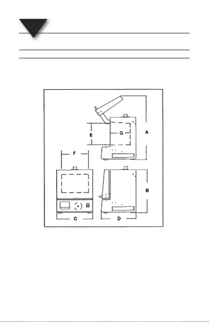
Exterior Dimensions: A: 25” (635 mm) B: 16.0” (410 mm)
Internal Muffle Dimensions: E: 7.0” (180 mm) F: 9.0” (230 mm)
C: 15.8” (400 mm) D: 17.0” (430 mm)
G: 9.0” (230 mm)
Figure - 7-2 Dimensions
Chamber Size: 550 cubic inches (9.13 liters)
Cabinet Construction: 16 guages steel with baked epoxy finish
Furnace Weight: 47 lb (21.3 kg)
Shipping Weight: 54 lb (24.5 kg)
7 - 2
Page 23
LMF-3550 Series
8
Introduction
This manual is in two parts - the first half covers
the LMF-A550
covers the LMF-3550
1.1 General Description
LMF Series Benchtop Muffle Furnaces feature a 550 cubic inch
chamber with fiber insulation and firebrick heating plates.The furnace
cabinet is constructed of 16 gauge steel with a backed epoxy finish. A
top exhaust port allows gases to be vented or may be plugged during
operation to seal the opening. Two temperature controller models are
available: automatic and multi-stage programmable. LMF series
furnaces are ideal for hear treating applications, material research and
sample ashing determinations in the geological, metallurgical, and
wastewater treatment industries. These furnaces are also used in
chemistry, physics, and engineering laboratories.
1.2 LMF-3550 Series Furnace Description
The Model LMF-3550 furnace has a 3-stage programmable temperature
controller which stores up to10 programs in memory. Any tow programs
can be linked to create a single six-stage program. One program is
dedicated to a single set point that holds the setpoint indefinitely. The
delay cycle allow the furnace to be set to its heating cycle at a specific
time on a future date.The PID controller allows heat increase and
decrease to be programmed into the cycle.
Series Furnaces. The second half
Series Furnaces.
1.3 Features
• High performance/hybrid muffle
• Longer life and more durable than Fiber
• Faster heating, and faster cooling than Firebrick
• Wide operating temperature range 50˚C (122˚F) to 1100˚C (2012˚F)
• Smooth, low force vertical lift door, with roll back action which gives
maximum access with minium vertical space
8 - 1
Page 24

8
Introduction LMF-3550 Series
• Programmable controller wtih 9 three stage programs (6 segments
each) and 1 program with a single temperature hold
• Heavy duty construction with stainless steel front panel
• Delay Start operation that enables the user to program the cycle
completion time rather than calculating the start time
• Easy to operate and program with user friendly graphic interface
• Programs linkable for 6 stage operation
• Integrated door safety switch breaks both sides of the power line to
muffle
• Wide programmable linear temperature rates both positive and
negative (0.1˚ to 40˚C/minute)
• Designed for Safety Agency Approvals, (CSA & TÜV Pending)
• Individual muffle beating plate replacement
• One plate services both voltages
8.4 Available Models
Part Number Volts Controller Type
LMF-A550/120 100-125 Programmable
LMF-A550/240 200-250 Programmable
8 - 2
Page 25

9
LMF-3550 Series
Installing the Furnace
1. Remove all packing material from in and around the furnace.
The furnace should be located at least 15 cm (6”) away form
walls, shelves and heat sensitive materials. Open the furnace
door and remove the packing material from inside the furnace.
NOTE
The furnace front panel may show some discoloration
around the muffle due to the calibration and burn-in cycles
performed at the factory.
2. The furnace should not
other airflow restrictions.
3. On high voltage (200-250 volt) units, connect the power cord to
the socket in rear of furnace.
4. For positioning the furnace:
a. (Combustion, Burnout or Reaction Processes) Position the
furnace under a vent hook or connect the exhaust port to a
ventilation system to prevent exposure to the exhaust
fumers. The furnace exhaust port 258 mm (1”) OD by 25
mm (1”) long can be ducted into the exhaust hood for more
effective ventilation. Stainless Steel flexible metal tubing
can be used for this ducting.
be located directly under shelves and
b. (Heat Treating or Non-Reaction Processes) Position the
furnace under a vent hood. Plug the exhaust port with the
ball plugs provided in the furnace accessory kit. This will
reduce heat loss and electricity requirements.
5. Connect the furnace to a power circuit or receptacle with an
overcurrent protection (circuit breaker or fuse) rating of 20
Amps on the low voltage model and 10 Amps on the high
voltage model. The circuit should only supply the furnace.
6. Turn on the furnace’s green power switch (at the right side of
the control panel) and the LCD display will come on. The light
in the green power switch lights when the door is closed and
the start key is pressed.
9 - 1
Page 26
9
Installing the Furnace LMF-3550 Series
7. At this time, your new furnace should be ready to operate.
Review Sections 11.1 and 11.2 of this manual before
proceeding to select special options.
9 - 2
Page 27
LMF-3550 Series
10
Operating the Furnace
10.1 Safety Considerations
- Never operate the furnace in close proximity to combustible materials
or place materials on top of the furnace.
- The furnace must be electrically grounded to a three-wire electrical
outlet or receptacle. The electrical service provided must be a
dedicated line of the proper size according to local electrical codes.
- Disconnect the line cord before attempting to service the furnace.
- Do not operate the furnace controls with tongs or other tools; the tongs
will damage the control switches.
- Do not use solvents or liquid cleaners on the control panel; they will
enter the panel and damage it.
- Do not place firing trays or other hot objects directly in front of the
furnace; they will melt the graphic overlay.
- Always verify that the power switch light is off before attempting to load
or reach into the furnace chamber with any tools or instruments.
- As a routine working precaution, always wear safety glasses and
protective gloves when operating, loading and unloading the furnace.
OSHA AND CALIFORNIA PROPOSITION 65:
MUFFLE DUST EXPOSURE
In keeping with the policy of OMEGA Engineering to build safe products,
comply with all National and State statutes and keep you, the valued
customer informed; the services of a Certified Industrial Hygienist firm
were employed to test and evaluate the lab operator’s exposure to
respirable refractory ceramic fiber (RCF) and crystobalite (a for of
crystalline silica) present tin the furnace muffle.
The findings of this test revealed that levels of exposure during the
normal operation of this equipment, as outlined in the Operator’s
Manual, were far less than the Permissible Exposure Limit set by the
Federal Government.
10 - 1
Page 28

10
Operating the Furnace LMF-3550 Series
When it becomes necessary to replace the muffle, the person doing this
work is recommended to wear HEPA filter respirator and protective
gloves as a precautionary matter.
Seal used muffle in a plastic bag and dispose of in accordance with
local, state and Federal regulations.
Because this product and many similar products on the market today
contain crystalline silica and ceramic fibers, it is necessary under the
statutes of California Proposition 65 that OMEGA Engineering include
the following statement:
“This product contains substance(s) known to the State of California to
cause cancer.” Material Safety Data Sheets for RCF materials supplied
upon request.
Designed to meet Canadian Standards Association (CSA), TÜV and
Underwriters Laboratories (UP) safety requirements.
10.2 Running a Program
The furnace has 9 three stage programs and one single temperature
hold program. The furnace is sold with the program parameters set to
the factory defaults which can be used for testing. First time operation
will require the user to enter their desired parameters into one of these
programs.
10 - 2
1. Turn on green power switch (right side of control panel). After a
short delay for testing, the furnace will display approximate
room temperature, program time (hours:minutes), and program
number. All red LEDs are off. (If any of the LEDs are on, the
furnace was already running a program when it was last turned
off.) The green power switch will light when the door is closed
and te Start key is pressed
2. Select or change the program to the desired number by
pressing the digit key (1-9) for the desired program followed by
the ENTER key. The display will be updated to show the
new program number and its approximate run time.
3. Pressing the green Start key will start this program.The
red LEDs will come on and the time will start to count down.
The LEDs will be turned off as each segment of each stage of
the program is completed.
- During the operation of the program, the total program
operation or cycle time is counting down as indicated by the
flashing colon in the time.
Page 29
LMF-3550 Series Operating the Furnace
- If a program is started when the muffle is already heated the
furnace will heat or cool at the first ramp rate to the first
temperature from the current muffle temperature. It will not
cool to room temperature before starting.
- The program will end by maintaining the last muffle
temperature, displayed “Hold”, beeping every 3 seconds and
flashing the last Temp LED. See information on End Of
Program options (point 1) in the “Setup & Maintenance”
sections if other operations are performed.
10
4. Pressing the key will change the temperature display from
5. A short power outage during the operation of a program will not
6. Pressing the Escape key cancels beeping at the end of a
7. Opening the door during a cycle interrupts power to the heating
˚C to ˚F and back.This key is not active during parameter
programming.
terminate or abort the program unless the muffle temperature
drops more than 32˚C (58˚F). If the power outage occurs when
the muffle temperature is close to or at room temperature (eg.
during Delay Start operations), the furnace will continue the
program when power is restored regardless of the temperature
drop or the amount of time that has expired.
program. It also will return the furnace to a display of the
current conditions during programming operations.
elements. The display shows “Door” but the program timer
continues if the program is in a hold portion of the program. If
the “Door” timer is activated (see Section 11.1), the furnace will
beep indicate the open door.
10.3 Stopping a Program
Pressing the red Stop key will stop the program that is currently
running. The red LEDs will go out and the display will show the current
program number, approximate cycle time and the current muffle
temperature.
10 - 3
Page 30

10
Operating the Furnace LMF-3550 Series
10.4 Programming
The furnace increases productivity and reliability for the operator
because cycles or programs can be preprogrammed and operate
automatically. Once programmed, the parameters are retained in
memory even with the loss of power. Parameters are not retained in
memory if entered during the operation of a program.
Each program is made up of 3 stages which require 3 parameters each.
The parameters are grouped into ramp rates (R1, R2, R3), temperatures
(T1, T2, T3), and dwell or hold times (H1, H2, H3). The 1, 2, 3 indicates
the stage number or sequence. The temperatures can be programmed
in either ˚C or ˚F; the ramp rates in ˚C per minute or ˚F per minute; and
the hold times in hours and minutes (hh:mm).
10.4.1 Ramp Rates (R)
10 - 4
1. Pressing the Rate key make the display show the current
value of the R1 parameter followed by 3 blanks for a new value.
For example: R1 8.0˚C/M->_ _ _
The corresponding LED will also light to indicate the selected
stage and parameter.
2. Use the digit keys (0, 1, 2...9) to enter the desired parameter
value followed by the ENTER key. The new parameter is
not stored in memory.
If a value is entered that is out of the acceptable range, the
furnace will beep and display the acceptable range.
Programming a Rate to 0 will cause the furnace to terminate
the remainer of the program stages. For example if R2 is set
equal to 0 then at te end of the first hold time (H1) the furnace
will go to the end of the program making the program single
stage.
3. Pressing the Rate key additional time will display and give
access to the Rate parameters for the other two stages.The
4th time the key is pressed the display circulates back to the
beginning and the R1 parameter will be displayed again.
The Rate key operates the same if pressed during the
operation of a program with the following exception. The new
Rate entered is used only for that one program or cycle and not
stored in memory.
Page 31
LMF-3550 Series Operating the Furnace
Negative ramp rates are also possible if slower than natural
cooling.
10.4.2 Temperatures (T)
10
1. Pressing the Temp key makes the display show the
2. Use the digit keys (0, 1, 2 ... 9) to enter the desired parameter
3. Pressing the Temp key additional times will display and
current value of the T1 parameter followed by 4 blanks for a
new value.
For example: T1 160˚C -> _ _ _ _
The corresponding LED will also light to indicate the selected
stage and parameter.
value followed by the ENTER key.The new parameter is
now stored in memory.
If a value is entered that is out of the acceptable range the
furnace will beep and display the acceptable range.
give access to the Temp parameters for the other two stages
The 4th time the key is pressed the display circulates back to
the beginning and the T1 parameter will be displayed again.
The Temp key operates the same if pressed during the
operation of a program with the following exception. Any new
parameter entered is used only for that one program or cycle
and not stored in memory.
10.4.3 Hold Times (H)
1. Pressing the Hold key makes the display show the
current value of the H1 parameter followed by 4 blanks for a
new value.
2. Use the digit keys (0, 1, 2 ... 9) to enter the desired parameter
3. Pressing the Hold key additional times will display and
value up to 99 minutes and 59 seconds followed by the ENTER
key.
The new parameter is now stored in memory.
give access to the Hold parameters for the other two stages.
The 4th time the key is pressed the display circulates back to
the beginning and the H1 parameter will be displayed again.
10 - 5
Page 32
10
Operating the Furnace LMF-3550 Series
The Hold key operates the same if pressed during the
operation of a program with the following exception. Any new
parameter entered is used only for that one program or cycle
and not stored in memory.
10.4.4 Program 0
Program 0 is a single temperature hold program. The furnace will heat to
this temperature and maintain it as long as power is applied.
1. Press the 0 key. The display shows the current programmed
2. Use the digit keys (0, 1, 2 ...9) to enter the desired temperature
3. Pressing the Start key will cause the furnace to heat to full
temperature and the 0 program number.
For example: T0 100˚C -> _ _ _ _
followed by the ENTER key. The new parameter is now
stored in memory aft 3 seconds.The display shows: 100˚C
***** 0, where 100 is the current muffle temperature, 0 is the
program number and ***** indicates that the program is not
started.
power to the programmed temperature. The display will show
“xxxx˚C “Hold* 0”. “xxxx” is the current muffle temperature, the
word “Hold” illustrates single stage and 0 is the program
number.The T1 LED will also be on.
10.5 Special Features
10.5.1 Delay Start (D)
The Delay Start functions as a timer that automatically starts a program
so that it is completed at the selected time up to 7 days later.The delay
is programmed in terms of the number of delay days and the desired
completion time. The furnace uses a clock to keep track of time when
the furnace power switch is on. If a power outage should occur during a
“Delay Start” the completion time would be delayed by te length of time
the power was off.
10 - 6
Page 33
LMF-3550 Series Operating the Furnace
Programming the Delay Start
10
1. Pressing the Delay Start key makes the display show the
2. Use the digits keys (0, 1, 2 ... 7) to enter the current time of day
3. Pressing the Delay Start key again makes the display
4. Use the digit keys (0, 1, 2, ... 7) to enter the desired number of
5. Pressing the Delay Start key again displays the program
current value of the time of day and beep.
For example: Now 7:30 -> ______
The corresponding LED will also light to indicate the Delay
Start is selected.
followed by the Enter key. The new parameter is not
stored in memory.The time of day must be entered in as a 24
hour clock 11:34 PM is 23:34).
shoe the current value of the Delay D parameter in days.
For example: Day; 1 (1, 2 ... 7)
The corresponding LED will also light to indicate the Delay
Start is selected.
days of delay followed by the ENTER key. The new
parameter is now stored in memory.
If a value entered is greater than 7, then the furnace will display
and use 7.
completion time. The furnace will calculate the approximate
time that the program needs to start so that it is completed by
the programmed time.
For example; End = 8:00 -> _ _:_ _
he computer uses a 24 hour clock. For example if 14:30 is
programmed, the completion time is 2:30 PM.
6. Pressing the Delay Start key again will shoe the actual
time (Now).
Pressing the key additional times will cycle through the other
parameters. Press the Escape key to stop the function.
10 - 7
Page 34
10
Operating the Furnace LMF-3550 Series
Running a Delay Start Program:
1. Select the desired program number (See Section 3.2).
2. Pressing the Delay Start key the display shows the
3. Pressing the green start key will start the delay timer.
programmed delay in days.
- The corresponding LED will also light to indicate the Delay
Start is selected.
- If the program run time is longer than the current delay time
the furnace will skip the delay and start the program
immediately.
10.5.2 Linking Programs
Programs can automatically run in sequence by using the Linking
feature.With this method a 6-stage (12 segment) program can be run
automatically. Additional programs can also be linked as each program
is completed.
Running Linked Programs:
1. Pressing the green Start key with the first program that is
2. Use the digit keys (1, 2 ... 9) to enter the next program number
to be run. The furnace will start operation.
to be run followed by the ENTER key. The furnace will now
run the first program followed automatically by the second.The
program or cycle time on the display will alternately show the
first program and then the second program number will be
displayed for a shorter time.
10 - 8
Page 35

LMF-3550 Series Operating the Furnace
10
10 - 9
Page 36
10
Operating the Furnace LMF-3550 Series
Notes
10 - 10
Page 37
11
11.1 Setup
LMF-3550 Series
Setup & Maintenance
The furnace goes though a self test that lasts for 4 to 6 seconds each
time that power is applied. After the test the display shows the word
“SETUP?” for approximately 5 seconds. In the Setup mode several
different options are available for the used to select.
The first is the END OF PROGRAM operation which allows the user to
select how the furnace should operate at the end of the program. The
second is the TMAX parameter which limits the maximum temperature
that can be programmed into the furnace. The third is the “Door” timer
which sounds an alarm if the door is not closed before the programmed
time out. The last is TEMPERATURE ADJUSTMENT/CALIBRATION
which allows the user to alter the furnace temperature calibration.
1. Turn on power to the furnace. Pressing the ENTER key
2. Pressing the ENTER key when the desired End Of
when the word “Setup?” is being displayed will start the Setup
mode first with the End of Program options.
The current END OF PROGRAM option is now displayed as
“Hold = 1 (2), (3)”. The (1) option is the factory default. It will
cause the furnace to maintain or hold the last programmed
temperature, display “Hold” and beep every 3 seconds until the
red Stop key is pressed. Pressing the Escape key
will stop the beeping but not the program.
he (2) option will cause the furnace to maintain or hold the last
programmed temperature, display “Hold” but without beeping
until the red Stop key is pressed.
The (3) option will cause the furnace to turn off and cool to
room temperature at the end of the program and display “End”.
The Stop key does not have to be pressed.
Use the digit keys (1, 2, 3) to change the END OF PROGRAM
option.
Program is selected will store it in memory and then advance
to TMAX which is the next option. The TMAX value limits the
maximum temperatures that the furnace can be programmed to
or fire to. The factory setting for TMAX is 1100˚C. Use the digit
keys (0, 1, 2 ... 9) to enter the desired TMAX value followed by
the ENTER key. The new Maximum Temperature is now
stored in memory and the next option is displayed.
11 - 1
Page 38
11
Setup & Maintenance LMF-3550 Series
3. The third option is the “Door” timer which is displayed as “Door
4. The final option is the temperature adjustment/calinration which
See the next section on Temperature Adjustment/Calibraton for specifics
on how to determine the adjustment number.
0Sec ->_ _”. This timer sounds an alarm when the door is open
for more than the preprogrammed time when a program is
running. This timer can be programmed from 1 to 99 seconds.
The factory default setting is 0 which disables the timer. Use
the digit keys (0, 1, 2 ... 9) to enter the desired “Door” timer
value followed by the ENTER key. The new “Door” time is
now stored in memory and the next option is displayed.
is displayed as “Tcal 1000˚C -> ____”. The factory setting for
Tcal is 1000˚C. Use the digit keys (0, 1, 2 ... 9) to enter the
desired Tcal value followed by the ENTER key.The new
Temperature Calibration is now stored in memory. Entering a
1000 will return the furnace to the factory calibration.
11.2 Temperature Adjustment/Calibrations
Every furnace is calibrated in the factory at 1000˚C. Under normal use
the furnace should not require calibration.The electronics used in the
furnace are very stable and will have minimal drifts over the life of the
furnace. Thermocouple replacement could be a potential requirement for
calibration if high accuracy is required.
This calibration can be altered by entering a new Tcal value in the Setup
mode listed previously. The Tcal value has a range of 900˚C to 1100˚C.
11 - 2
For example:
A program is operating at a stable temperature and a separate
thermocouple is inserted in the furnace and a digital thermometer
measures the muffle temperature.The display shows 875˚C whish is the
programmed temperature but the digital thermometer reads 868˚C. A
new calibration value could be calculated by dividing the display
temperature by the actual temperature (digital thermometer) and then
multiply by the current Tcal value (factory default is 1000˚C). In this case
the result is 1008 (875/868 = 1.008;1.008 x 1000 = 1008). 1008 is
entered in as the Tcal value.With this method the furnace calibration
can be done at normal operation temperature.
Page 39
LMF-3550 Series Setup & Maintenance
Second example:
Programmed temperature is 1050˚C and the digital thermometer reads
1065˚C.The old Tcal value is 985˚C.
(1050/1065 = 0.986 then 0.986 x 985 = 971). 971 should be entered as
the new Tcal value.
11.3 Cleaning
- Vacuum dust and dirt from the furnace rather than blow. This will
minimize the amount of airborne dust particles.
- Use a sot damp cloth to clean the control panel. Avoid excess water or
solution when cleaning the furnace. These solutions can attach the
panel or electronics and cause the furnace to malfunction.
11.4 Fuses
F250V @ 20A - Fast acting, ceramic (Bussman 3AB - 20 Amp, 250V)
F250V @ 1.0A - Fast acting, glass (Littlefuse 2AG - 1.0 Amp, 250V)
11
Symbol Table
- Alternating current
- On (Supply)
- Off (Supply)
- Hot Surface
- Protective Conductor Terminal
11 - 3
Page 40
11
Setup & Maintenance LMF-3550 Series
Notes
11 - 4
Page 41

12
LMF-3550 Series
Troubleshooting
Err codes can be cleared form the display by turning the front panel
power switch off and then on again.
Code Description Possible Cause
Err 1 Over Temperature Temp > 1120˚C, shorted
Err 2 Open Thermocouple Open TC tip, connection to
Err 3 Temp > Tmax Muffle temperature has
Err 7 Brown-out Low line voltage <90Vac
Err 8 EEPROM error Parameter program
Err 19 Line frequency No line frequency
thermocouple, shorted
triac, shorted optotriac,
wiring connections,
computer PCB
TC, TC to PCB
connection, computer
PCB
exceeded the
programmed limit
temperature TMAX (see
Setup in Section 11.1)
(<190Vac for 200-250V),
wall socket shared with
other loads, furnace
connected with small
extention cord
memory error: computer
PCB
detected, computer PCB
12 - 1
Page 42
12
Troubleshooting LMF-3550 Series
Problem Checklist/Causes
Dead, not operating - Check power receptacle or outlet
Not heating Does the green power switch
during program when the start key is pressed?
operation No: - Check door that it is
Door too loose or tight - The amount of force or drag on the
Heating too slowly - Rate programmed wrong.
for power
- Check line or power cord
connections
- Turn on green power switch
completely closed.
- Door switch may be
interrupting power.
Yes: - Check the fused on the
controller PCB
- Check heating element plates
for continuity.
door movement can be changed
by adjusting the hex screws
located on the upper rear corners
of the furnace cabinet. Turning the
screw clockwise adds drag and
requires more force.
1.5˚ / minute rather than 15.0˚ /
minute
- Large loads will slow down
response time by 2 to 5 times.
12 - 2
Program turns Programming a Rate to zero will
terminate the remainder of the
program.
End Of Program options has been
changed from 1 or 2 to option 3
which turns off the furnace at the
end of the program.
Page 43

13
LMF-3550 Series
Accessories
Description Part Number
Tongs; 25 cm (10”) Stainless Steel 9390014
Tongs: 30 cm (12”) Stainless Steel 9390015
Tongs: 36 cm (14”) Plated Steel 9491010B
Heating Plate (1) LMF-HP
Ceramic Floor Tray LMF-CFT
Thermocouple LMF-TC
Muffle Hardening Agent 9491006
Temperature, Pellets, Bottle of 25
705˚C (1300˚F) 9490911
815˚C (1500˚F) 9490912A
Exhaust port ball plug (small) 9491093A
13 - 1
Page 44
13
Accessories LMF-3550 Series
Notes
13 - 2
Page 45

LMF-3550 Series
14
Specifications
Parameter
Temperature Range: 122˚F to 2012˚F (50˚C to 1100˚C) / 1˚ Resolution
Hold Time Range; 0:00 to 99:59 (hours:minutes) / 1 Min Resolution
Ramp Rate Range: 0 to 40˚C/minute (72˚F) / 0.1˚C Resolution
Temperature Accuracy: ±45˚F (±25˚C) at steady state
Muffle Temperature
Uniformity: ±15˚F (±8˚C) at steady state
Air-Circulation: Top exhaust port
Muffle: Fiber insulation with firebrick heating plates
Electrical
Voltage Ranges: 100 to 125
@ 50/60Hz 200 to 250
Current (amps)
125V: 18 to 14.4
250V: 9 to 7.2
Input Power (watts): 1800
Max Ramping Power: 2000
Watts to Maintain 1000˚C: 1050
Environmental
Ambient Operating
Temperature: 5˚ to 40˚C
Relative Humidity: Maximum 80%, non-condensing
Figure 14 - 1. Performance Curve
14 - 1
Page 46
14
Mechanical
Specifications LMF-3550 Series
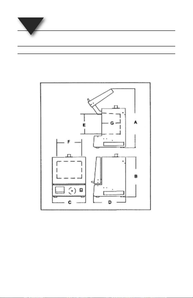
Exterior Dimensions: A: 25” (635 mm) B: 16.0” (410 mm)
Internal Muffle Dimensions: E: 7.0” (180 mm) F: 9.0” (230 mm)
C: 15.8” (400 mm) D: 17.0” (430 mm)
G: 9.0” (230 mm)
Figure 14 - 2. Dimensions
Chamber Size: 550 cubic inches (9.13 liters)
Cabinet Construction: 16 guages steel with baked epoxy finish
Furnace Weight: 47 lb (21.3 kg)
Shipping Weight: 54 lb (24.5 kg)
14 - 2
Page 47

WARRANTY/DISCLAIMER
OMEGA ENGINEERING, INC. warrants this unit to be free of defects in materials and
workmanship for a period of 13 months from date of purchase. OMEGA’s WARRANTY adds
an additional one (1) month grace period to the normal one (1) year product warranty to
cover handling and shipping time. This ensures that OMEGA’s customers receive maximum
coverage on each product.
If the unit malfunctions, it must be returned to the factory for evaluation. OMEGA’s Customer
Service Department will issue an Authorized Return (AR) number immediately upon phone or
written request. Upon examination by OMEGA, if the unit is found to be defective, it will be
repaired or replaced at no charge. OMEGA’s WARRANTY does not apply to defects resulting
from any action of the purchaser, including but not limited to mishandling, improper
interfacing, operation outside of design limits, improper repair, or unauthorized modification.
This WARRANTY is VOID if the unit shows evidence of having been tampered with or shows
evidence of having been damaged as a result of excessive corrosion; or current, heat, moisture
or vibration; improper specification; misapplication; misuse or other operating conditions
outside of OMEGA’s control. Components in which wear is not warranted, include but are not
limited to contact points, fuses, and triacs.
OMEGA is pleased to offer suggestions on the use of its various products. However,
OMEGA neither assumes responsibility for any omissions or errors nor assumes
liability for any damages that result from the use of its products in accordance with
information provided by OMEGA, either verbal or written. OMEGA warrants only
that the parts manufactured by the company will be as specified and free of
defects. OMEGA MAKES NO OTHER WARRANTIES OR REPRESENTATIONS OF ANY
KIND WHATSOEVER, EXPRESSED OR IMPLIED, EXCEPT THAT OF TITLE, AND ALL
IMPLIED WARRANTIES INCLUDING ANY WARRANTY OF MERCHANTABILITY AND
FITNESS FOR A PARTICULAR PURPOSE ARE HEREBY DISCLAIMED. LIMITATION OF
LIABILITY: The remedies of purchaser set forth herein are exclusive, and the total
liability of OMEGA with respect to this order, whether based on contract, warranty,
negligence, indemnification, strict liability or otherwise, shall not exceed the
purchase price of the component upon which liability is based. In no event shall
OMEGA be liable for consequential, incidental or special damages.
CONDITIONS: Equipment sold by OMEGA is not intended to be used, nor shall it be used: (1)
as a “Basic Component” under 10 CFR 21 (NRC), used in or with any nuclear installation or
activity; or (2) in medical applications or used on humans. Should any Product(s) be used in or
with any nuclear installation or activity, medical application, used on humans, or misused in
any way, OMEGA assumes no responsibility as set forth in our basic WARRANTY/ DISCLAIMER
language, and, additionally, purchaser will indemnify OMEGA and hold OMEGA harmless from
any liability or damage whatsoever arising out of the use of the Product(s) in such a manner.
RETURN REQUESTS/INQUIRIES
Direct all warranty and repair requests/inquiries to the OMEGA Customer Service Department.
BEFORE RETURNING ANY PRODUCT(S) TO OMEGA, PURCHASER MUST OBTAIN AN
AUTHORIZED RETURN (AR) NUMBER FROM OMEGA’S CUSTOMER SERVICE DEPARTMENT
(IN ORDER TO AVOID PROCESSING DELAYS). The assigned AR number should then be
marked on the outside of the return package and on any correspondence.
The purchaser is responsible for shipping charges, freight, insurance and proper packaging to
prevent breakage in transit.
FOR WARRANTY
RETURNS, please have
the following information available BEFORE
contacting OMEGA:
1. Purchase Order number under which
the product was PURCHASED,
2. Model and serial number of the product
under warranty, and
3. Repair instructions and/or specific
problems relative to the product.
FOR NON-WARRANTY REPAIRS,
consult
OMEGA for current repair charges. Have the
following information available BEFORE
contacting OMEGA:
1. Purchase Order number to cover the
COST of the repair,
2. Model and serial number of theproduct, and
3. Repair instructions and/or specific problems
relative to the product.
OMEGA’s policy is to make running changes, not model changes, whenever an improvement is possible.
This affords our customers the latest in technology and engineering.
OMEGA is a registered trademark of OMEGA ENGINEERING, INC.
© Copyright 2010 OMEGA ENGINEERING, INC. All rights reserved. This document may not be copied, photocopied,
reproduced, translated, or reduced to any electronic medium or machine-readable form, in whole or in part, without
the prior written consent of OMEGA ENGINEERING, INC.
Page 48

Where Do I Find Everything I Need for
Process Measurement and Control?
OMEGA…Of Course!
Shop online at omega.com
SM
TEMPERATURE
䡺⻬
Thermocouple, RTD & Thermistor Probes, Connectors, Panels & Assemblies
䡺⻬
Wire: Thermocouple, RTD & Thermistor
䡺⻬
Calibrators & Ice Point References
䡺⻬
Recorders, Controllers & Process Monitors
䡺⻬
Infrared Pyrometers
PRESSURE, STRAIN AND FORCE
䡺⻬
Transducers & Strain Gages
䡺⻬
Load Cells & Pressure Gages
䡺⻬
Displacement Transducers
䡺⻬
Instrumentation & Accessories
FLOW/LEVEL
䡺⻬
Rotameters, Gas Mass Flowmeters & Flow Computers
䡺⻬
Air Velocity Indicators
䡺⻬
Turbine/Paddlewheel Systems
䡺⻬
Totalizers & Batch Controllers
pH/CONDUCTIVITY
䡺⻬
pH Electrodes, Testers & Accessories
䡺⻬
Benchtop/Laboratory Meters
䡺⻬
Controllers, Calibrators, Simulators & Pumps
䡺⻬
Industrial pH & Conductivity Equipment
DATA ACQUISITION
䡺⻬
Data Acquisition & Engineering Software
䡺⻬
Communications-Based Acquisition Systems
䡺⻬
Plug-in Cards for Apple, IBM & Compatibles
䡺⻬
Data Logging Systems
䡺⻬
Recorders, Printers & Plotters
HEATERS
䡺⻬
Heating Cable
䡺⻬
Cartridge & Strip Heaters
䡺⻬
Immersion & Band Heaters
䡺⻬
Flexible Heaters
䡺⻬
Laboratory Heaters
ENVIRONMENTAL
MONITORING AND CONTROL
䡺⻬
Metering & Control Instrumentation
䡺⻬
Refractometers
䡺⻬
Pumps & Tubing
䡺⻬
Air, Soil & Water Monitors
䡺⻬
Industrial Water & Wastewater Treatment
䡺⻬
pH, Conductivity & Dissolved Oxygen Instruments
M2159/1210
 Loading...