

Page 1

e-mail: [email protected]
For latest product
manuals:
omega.com/en-us/
pdf-manuals
Shop online
at
omega.com
User’s Guide
Omega Link Cloud Guide
Page 2

omega.com [email protected]
Omega Engineering, Inc.
800 Connecticut Ave. Suite 5N01, Norwalk, CT 06854, USA
Toll-Free: 1-800-826-6342 (USA & Canada only)
Customer Service: 1-800-622-2378 (USA & Canada only)
Engineering Service: 1-800-872-9436 (USA & Canada only)
Tel: (203) 359-1660 Fax: (203) 359-7700
email: [email protected]
Omega Engineering,
Limited
1 Omega Drive, Northbank,
Irlam Manchester M44 5BD
United Kingdom
Omega Engineering,
GmbH
Daimlerstrasse 26 75392
Deckenpfronn Germany
For Other Locations Visit omega.com/worldwide
The information contained in this document is believed to be correct, but OMEGA accepts no liability for any errors it contains, and reserves
the right to alter specifications without notice.
Page 3

Table of Contents
Table of Contents ............................................................................................................................................................... 2
1 Notes, Cautions, and Warnings ............................................................................................................................... 3
2 Introduction .................................................................................................................................................................. 4
2.1 Cloud Account User Registration ............................................................................................................................ 4
3 Navigating the Omega Link Cloud User Interface ............................................................................................... 6
3.1 Devices ........................................................................................................................................................................... 6
3.1.1 Registering an Omega Link Gateway to Omega Link Cloud .......................................................................... 7
3.1.1.1 Gateway Details ......................................................................................................................................................................... 7
3.1.1.2 Situational Amber LED Status Indicator During Initial Boot-Up ................................................................. 8
3.1.2 Management .............................................................................................................................................................................. 8
3.1.2.1 Creating a Device Group and Adding Devices .................................................................................................... 8
3.1.2.2 User and Device Assignment ......................................................................................................................................... 10
3.1.2.3 Assign Gateway to Admin (Admin Only) ................................................................................................................ 10
3.1.2.4 Assign Alarm Notifications ............................................................................................................................................... 10
3.1.3 Sensor Analytics .................................................................................................................................................................... 11
3.1.3.1 Measurements .......................................................................................................................................................................... 11
3.1.3.2 Alarms and Events ................................................................................................................................................................. 12
3.1.3.3 Settings (Define Alarms and Events) ......................................................................................................................... 12
3.1.3.4 What is Deadband in Settings? .................................................................................................................................... 12
3.2 Historian ....................................................................................................................................................................... 13
3.2.1 How to Generate a Historical Data Report ............................................................................................................. 13
3.3 System Settings .......................................................................................................................................................... 17
3.3.1 Profile .......................................................................................................................................................................................... 17
3.3.2 Units ............................................................................................................................................................................................. 18
3.3.3 Users ............................................................................................................................................................................................ 18
3.3.3.1 How to Add Organizational Users .............................................................................................................................. 19
3.3.4 Subscription ............................................................................................................................................................................. 19
3.3.5 Contact Us ................................................................................................................................................................................ 19
3.4 How to Remove a Paired Smart Sensor from a Gateway ............................................................................. 20
3.4.1 How to Move a Paired Smart Sensor to a Different Omega Link Gateway .......................................... 20
2 | M5800
Page 4
1 Notes, Cautions, and Warnings
If the equipment is used in a manner not specified in this manual, the protection of the equipment may
be impaired.
Do not operate the equipment in flammable or explosive environments.
It is important to read and follow all precautions and instructions in this manual before operating or
commissioning this device as it contains important information relating to safety and EMC. Failure to
follow all the safety precautions may result in injury and/or damage to the equipment.
The following labels identify information that is especially important to note:
Note:
Caution or Warning:
Caution, Warning, or Important:
Provides information that is important to successfully navigate the Omega Link Cloud
user interface.
Informs about the risk of electrical shock.
Informs of circumstances that can affect the functionality of
the instruments and must refer to accompanying documents.
3 | M5800
Page 5
2 Introduction
Primary
Administrator
User
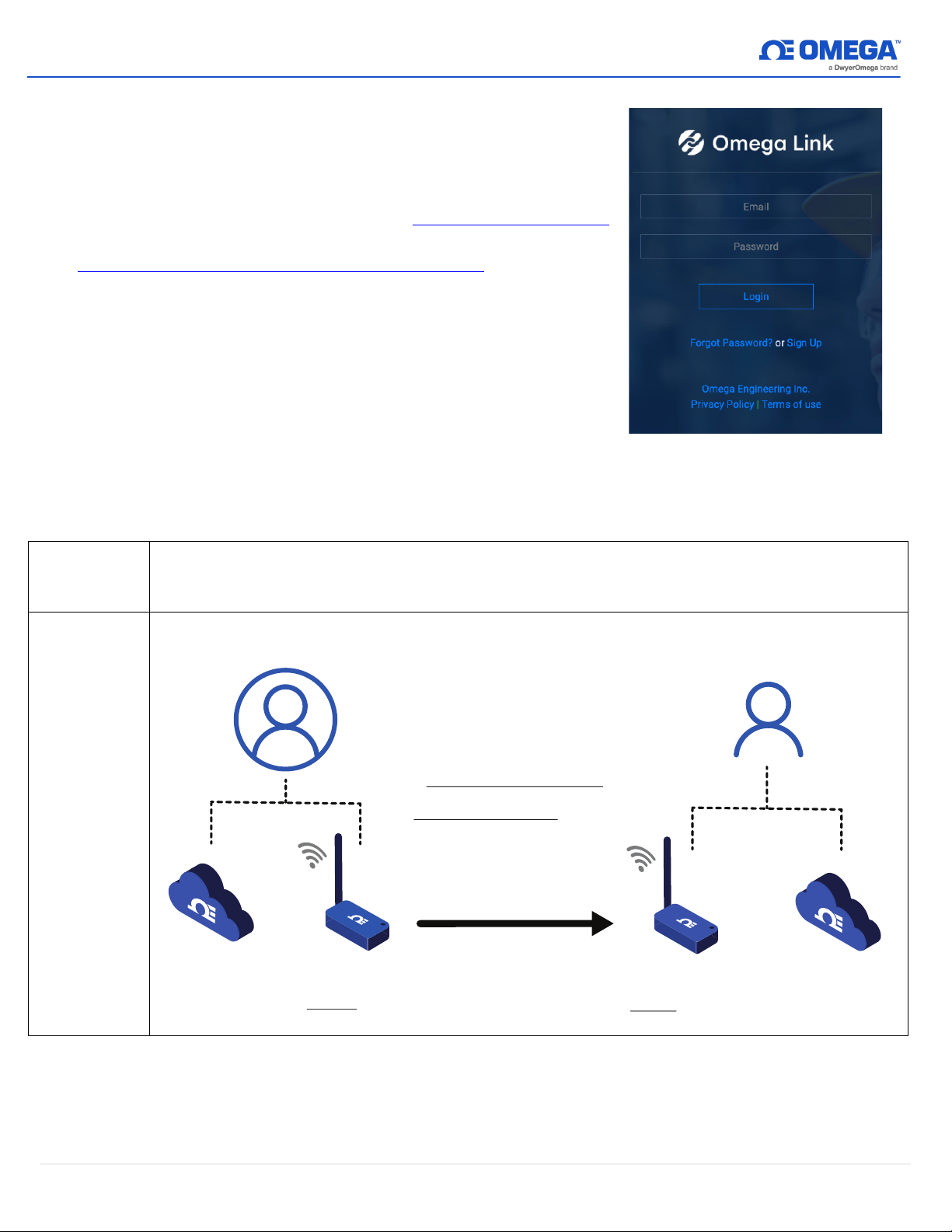
The primary administrator user account is the main account that the Omega Link Gateway
is originally registered to.
Non-Primary
Administrator
User
Primary Administrator
A Non-Primary Administrator is
assigned when the
Primary Administrator shares
access to the Primary
Adminstator’s Gateway
through the Device
Management button in Section
3.1.2.3.`
Non-Primary Administrator
Primary
Admininistrator’s
Cloud Account
Primary
Administrator’s
s
h
ared Gateway
Access to Primary
Administrator’s
shared Gateway
Non-Primary
Administrator’s
Cloud Account
Figure 1: Omega Link Cloud login
The Omega Link Cloud provides device management, state and
status monitoring, data logging, and analytics on all connected
rd
Omega Link Smart Sensing devices and compatible 3
sensing devices through a robust web user interface. Accounts
can be created and accessed by visiting: http://cloud.omega.com.
Subscriptions can be purchased by visiting:
https://www.omega.com/en-us/omega-link-cloud.
2.1 Cloud Account User Registration
Using any device with a web browser, complete the following
steps:
party
Step 1:
Step 2:
Open your browser to
Sign Up
Click
and complete the registration process.
cloud.omega.com
.
This will require a valid email address.
Below is a table describing the different kinds of users:
4 | M5800
Page 6
Non-
Administrator
User
Note:
Administrator
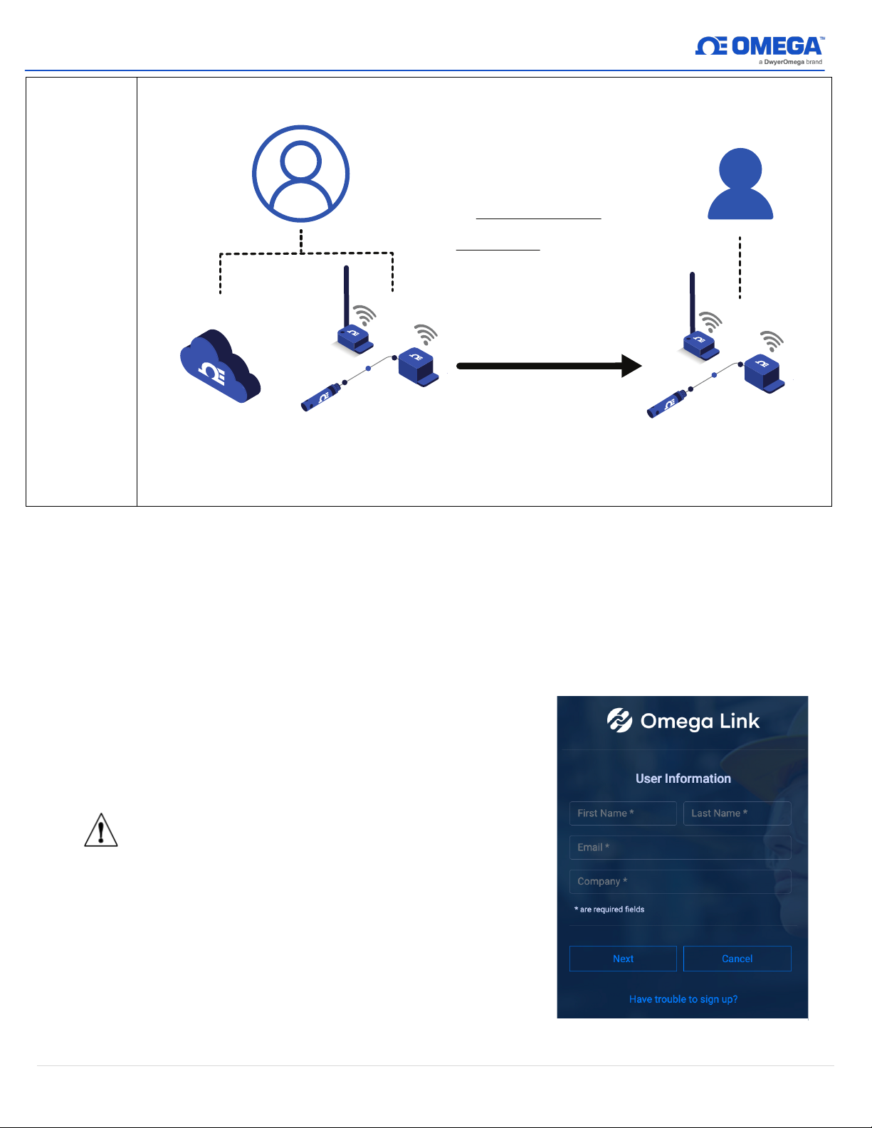
An Organizational User is
assigned when an
Administrator (primary or
non-primary) shares View and
Change access to the sensing
devices and their settings to
that user. Organizational users
are added as shown in Section
3.3.3.
Organizational User
Admininistrator’s
Cloud Account
Admininistrator’s
Sensing Devices
View or Change
access to the
Admininistrator’s
Sensing Devices
Figure 2: Administrator Account Sign Up
Only administrator users (primary or non-primary) need to register individual Omega Link
Cloud accounts. Organizational users do not need to register an Omega Link Cloud account.
If one account will be shared among multiple users in a company/ organization, it is highly
recommended that access to the email address account be created and shared among all
team members who will have primary administrator access in case of organizational changes.
(Ex: [email protected])
Once the user credentials are verified, the user can login to the
primary administrator account and will be presented with the
Omega Link Cloud homepage. The primary administrator will
have the opportunity to register Omega Link Gateways,
change subscription tiers, and create additional user accounts.
Important:
If multiple Administrator users will be
registered under the same company name,
it is important that the company name be
typed the same way for each admin
registration to ensure proper operation
when assigning devices.
5 | M5800
Page 7
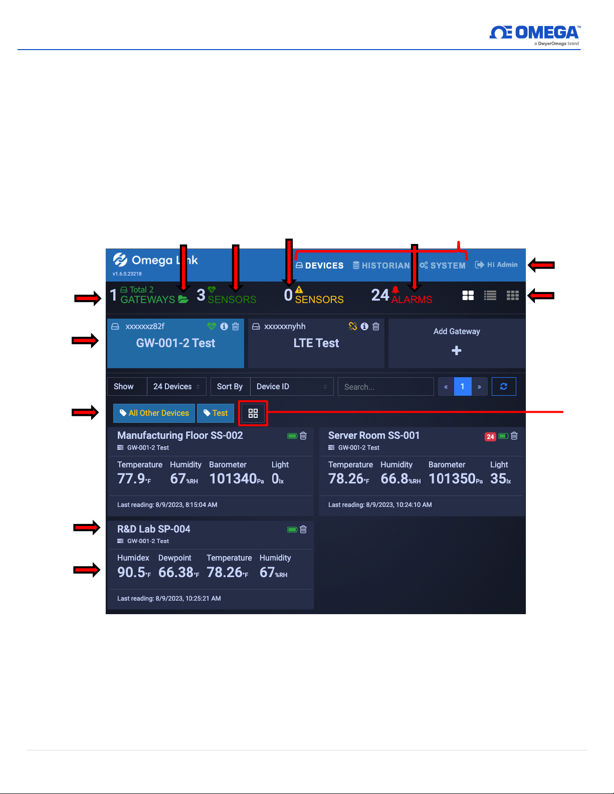
3 Navigating the Omega Link Cloud User Interface
Operation
Overview
Gateway
List
Filter
Devices
Device
Readings
Device
Name
View
Types
Show/Hide
Gateway
Types
Normal
Operation
Sensors
(3 devices)
Sensors Need
Attention
(0 devices)
Alarm Event
Count
(24 alarms)
Primary User
Interface Tabs
Log
Out
Device
Management
The primary user interface tabs (
Devices, Historian
in the sections that follow.
3.1 Devices
After signing in, the
Devices
tab immediately presents the readings of all registered Omega Link
Gateways and their connected sensing devices. From here, users may access connected gateway
details, add additional gateways to the cloud account, monitor device health, and access specific
sensor analytics.
, and
System
) and their functionality are described
Figure 3: Omega Link Cloud Devices tab
6 | M5800
Page 8
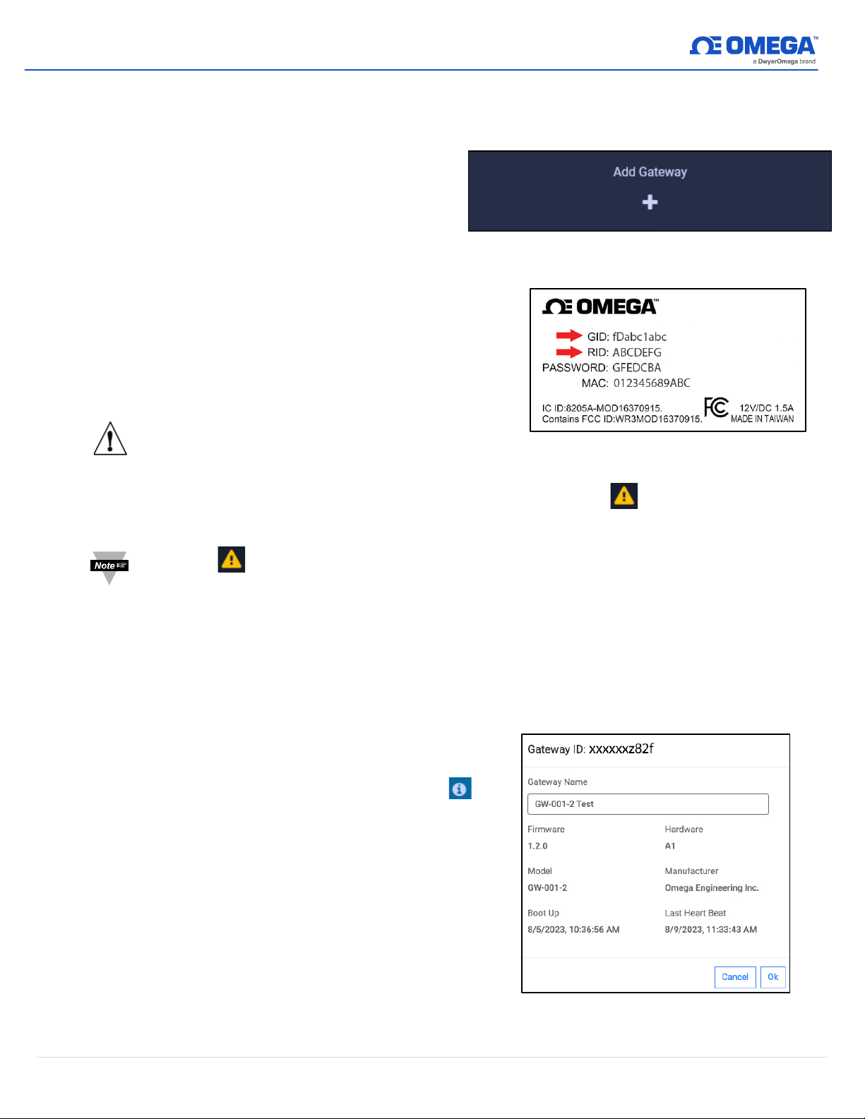
3.1.1 Registering an Omega Link Gateway to Omega Link Cloud
Figure 6: Omega Link Cloud registered gateway
details
Figure 4: Omega Link Cloud Add Gateway button
Figure 5: Sample Omega Link Gateway label
After logging in, follow the steps below to connect an Omega Link Gateway to the Omega
Link Cloud.
Step 1:
Step 2:
From the Omega Link Cloud
Devices homepage, click
Gateway
Type in the
.
Gateway ID (GID)
Add
from the
label on your gateway.
Step 3:
Type in the
label on your gateway and click
Important:
The label containing your Gateway ID
Registration ID (RID)
from the
Register
.
and Register ID is located at the bottom of the
gateway unit.
Step 4:
Once the gateway has been successfully registered, an icon will appear next to
your registered device.
Note:
The icon indicates incomplete device provisioning between the Omega Link
Gateway and the Cloud. If the icon persists for more than 5 minutes after the gateway
registration, power cycle the gateway device to reattempt device provisioning. Users
can access the internal gateway UI to check the status log of the device if the issue
persists.
Once you have access to your account and have completed your initial device pairing, you
will be presented with your connected devices on the Omega Link Cloud interface.
3.1.1.1 Gateway Details
To view your gateway details or change
the name of your device, click the
icon associated with the gateway you
wish to view. From here, you will be able
to change your gateway name and view
your gateway ID, firmware version, model
number, initial boot-up date and time,
hardware type, manufacturer, and last
recorded device heartbeat.
7 | M5800
Page 9
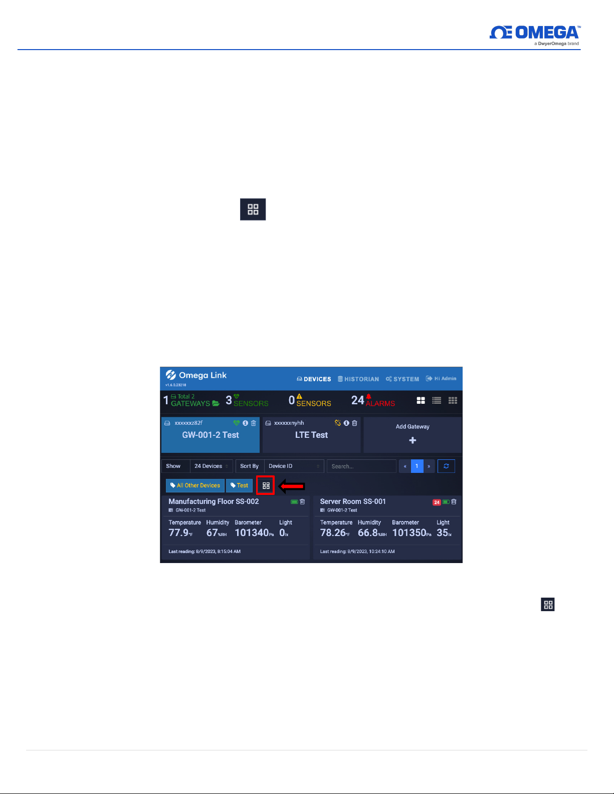
3.1.1.2 Situational Amber LED Status Indicator During Initial Boot-Up
Occasionally, the LED status indicator of the Omega Link Gateway will display a solid
amber light. This solid amber light indicates that there is no internet connection to the
Omega Link Gateway. This can be verified by navigating to the internal gateway user
interface using a web browser (refer to the Omega Link Gateway user’s manual for
more information on accessing the internal gateway user interface). Should this occur,
the user or company’s IT department must open firewall ports and IP addresses to
allow the connection to occur.
3.1.2 Management
Clicking the Management icon allows administrator users to create customizable
groups of gateways, assign gateways to other admintrators, and assign gateway alarm
notifications to other users. The “Group” feature allows admin users to group gateway
devices and organizational users. Groups of users will have permission to view, change,
and/or receive alarm notifications from the sensors associated with the gateways in the
group.
3.1.2.1 Creating a Device Group and Adding Devices
To create a
Device Group
and add sensing devices to that group, follow these
instructions:
Step 1:
Figure 7: Omega Link Cloud devices homepage
On the Omega Link Cloud homepage, click on the Management icon .
8 | M5800
Page 10
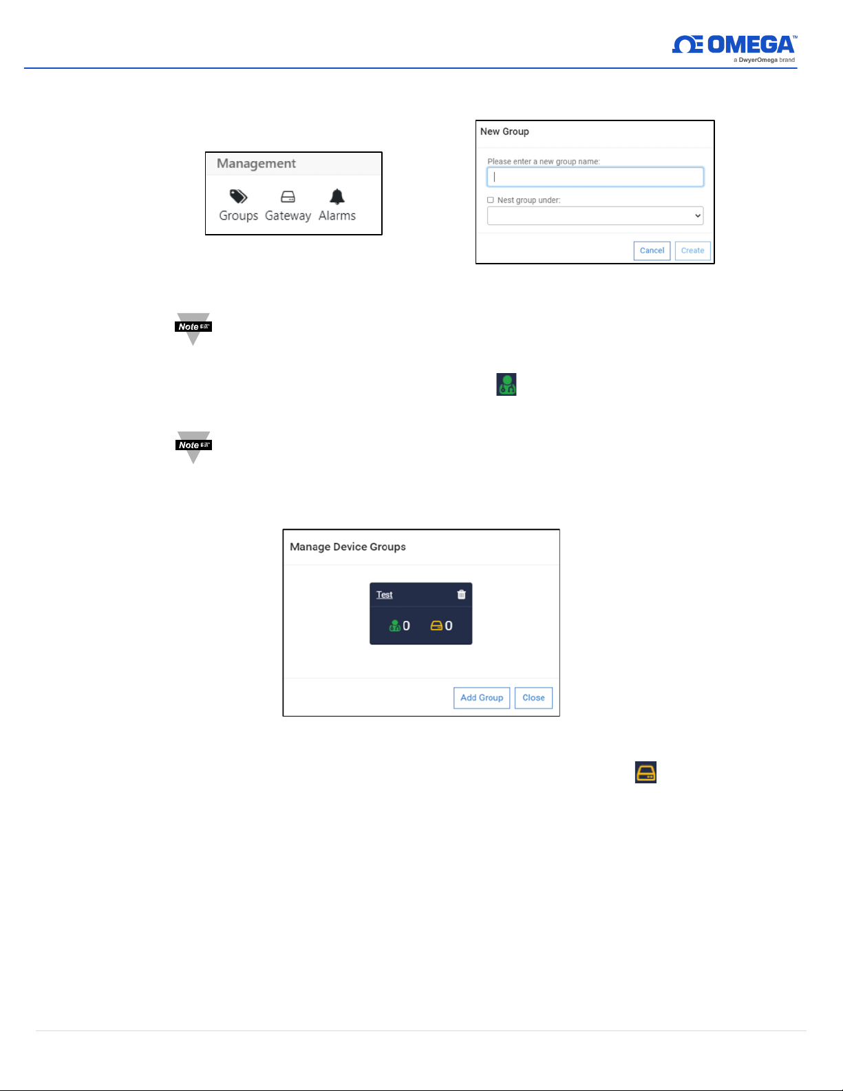
Step 2:
Figure 9: New Group Interface
Figure 8: Device Management
options
Click
Create
Groups
to finalize.
, then click
Add Group
and create a name for your group. Click
Note:
Step 3:
Note:
The dropdown for
Nest Group Under
can be disregarded.
Once your group is created, a pop-up window will appear with the title
Manage Device Groups
grant them access to the group. Click
. Click the icon to add a user’s email address and
OK
to finalize the changes.
Before adding a user to a group, the user must be granted access to the
Omega Link Cloud account by completing the steps outlined in section
3.3.3.1 How to Add
.
Step 4:
Figure 10: Device group management interface
Once back on the
Manage Device Groups
window, click the icon to add
sensing devices to your newly created group. Click
OK
to finalize the changes.
9 | M5800
Page 11
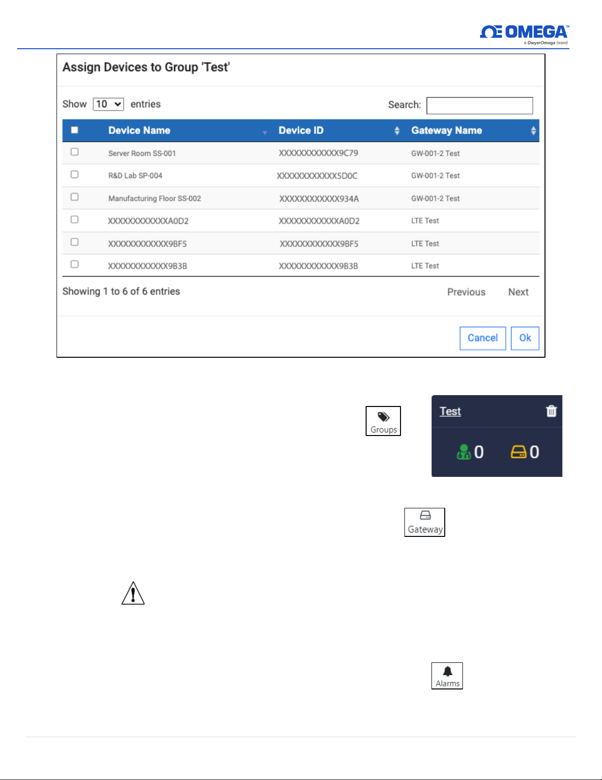
Figure 11: Assigning a device to a specific group
Figure 12: Omega Link Cloud
Users and Groups
3.1.2.2 User and Device Assignment
To assign users to devices, click the Groups
icon, and click
Add Group
. After naming your group, you
can click on these icons to add users and devices to
your group.
3.1.2.3 Assign Gateway to Admin (Admin Only)
To assign a gateway to an admin, click the Gateway icon. Enter the admin’s
email address and select the gateway that will be assigned to them. Click
Gateway
to finalize.
Assign
3.1.2.4 Assign Alarm Notifications
Important:
If multiple Administrator users will be registered under the same
company name, it is important that the company name be typed the
same way for each admin registration to ensure proper operation when
assigning devices.
To assign gateway alarms to other users, click the Alarms icon. Select your
gateway, select the users to be assigned the alarm notifications, and click
Assign
to finalize.
Confirm
10 | M5800
Page 12
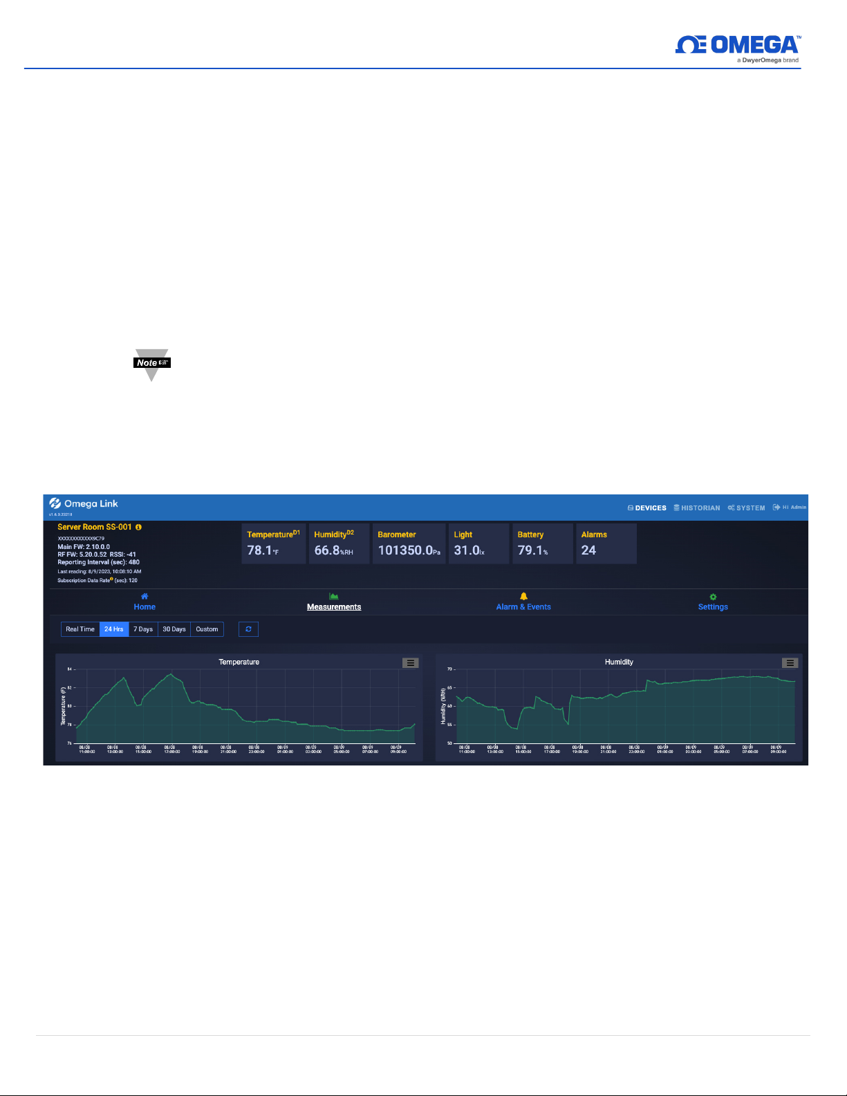
3.1.3 Sensor Analytics
To access the analytics of a specific sensor, click on the measurements of the sensor you
wish to view.
3.1.3.1 Measurements
The measurements tab displays graphs of the readings recorded by your sensor. It
allows users to change between live readings and specified ranges of time. All data
points, except for
for 7 days and 30 days. Custom range downsampling will be based on the Reporting
Interval when plotted on the Omega Link Cloud interface regardless of the Cloud
subscription level. All Real Time logged data fully remains in the Historian. See
section
Note:
3.2 Historian
Data backfilled from offline sensor devices will not have the subscription level
downsampling rate appear in the Measurements chart if the custom range is
greater than 24 hours. However, the data gathered while the sensor was offline
(but still powered on) is preserved as long as there is still space in the internal
memory. In case the sensor memory is full, the oldest data will be overwritten
first.
Real Time
, are downsampled to 10 minutes for 24 hours and 1 hour
for more information.
Figure 13: Omega Link Cloud sensor measurements – Graph View
11 | M5800
Page 13
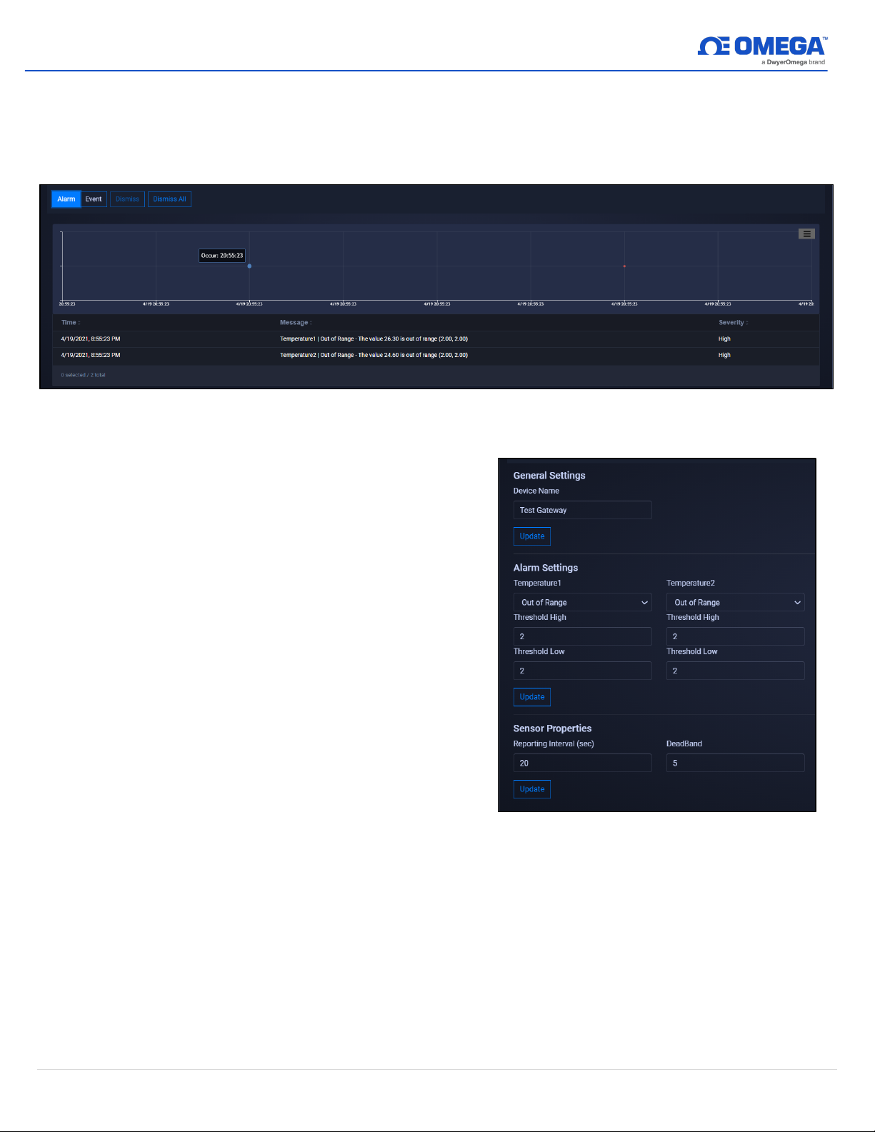
3.1.3.2 Alarms and Events
Figure 15: Omega Link Cloud Settings
The Alarms and Events tab displays all alarms and events that were triggered by this
device. Each alarm and event include a short message describing the nature of the
alarm or event.
Figure 14: Omega Link Cloud Alarms and Events interface
3.1.3.3 Settings (Define Alarms and Events)
The Settings tab allows users to
change all settings relevant to how the
device interacts with the Omega Link
Cloud. Users can customize the device
name, alarm/event thresholds, and
sensor reporting properties.
To set a local alarm output once you
are in the
Settings
tab, define the
parameters of the alarm by defining
the threshold. Your alarm can be
configured to trigger when readings
Above, Below
go
Out of Range
, or
your defined threshold. Once you have
defined your alarm parameters, click
Update
to finalize your changes.
3.1.3.4 What is Deadband in Settings?
It is standard to establish the desired threshold or setpoint to trigger an alarm when a
condition is met. Triggering an alarm repeatedly in a short period, however, can
produce unwanted results, such as having the alarm flip between inactive and active
several times and triggering unwanted actions tied to that alarm as a result.
Additionally, the constant alarm email notifications may result in an email service
shutdown.
To solve the alarm chattering issue, Omega has implemented a Deadband feature into
of
12 | M5800
Page 14
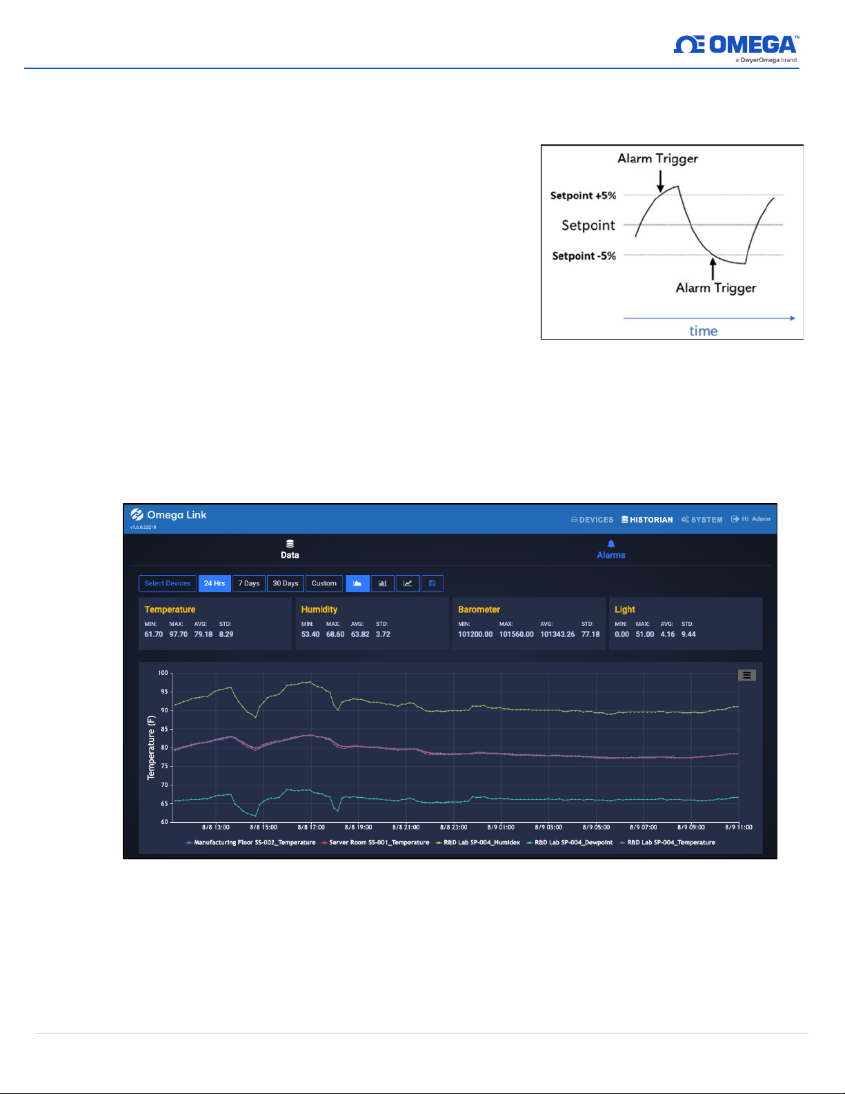
the Omega Link Cloud. Also known as hysteresis, the deadband establishes a range,
Figure 16: Setpoint as a percentage
or threshold, of values from the setpoint that the Omega Link Cloud will accept before
the alarm is triggered. The deadband threshold can either be defined as an absolute
value or as a percentage of the setpoint value.
In the Omega Link Cloud, the deadband
feature in the alarm settings is expressed as a
percentage. For example, if a user enters a
value of 5 in the deadband text box, a range of
+5% to -5% from the threshold has
been
established and the alarm will not be triggered
within that region.
3.2 Historian
The Historian tab allows users to create reports of past readings within a range of time and presents
them as a graph. Through the Historian tab, users can export their chart data as a .csv file. Begin by
clicking
Select Devices
and making your selection. Select the range of time your wish to view and
choose a graph type from the selection. Your data will then be displayed and ready for export.
3.2.1 How to Generate a Historical Data Report
The Historian tab allows users to create reports of past readings within a range of time and
presents them as a graph. Through the Historian tab, users can export their chart data as a
.csv file. Begin by clicking
time your wish to view and choose a graph type from the selection. Your data will then be
displayed and ready for export.
Figure 17: Omega Link Cloud Historian interface
Select Devices
and making your selection. Select the range of
13 | M5800
Page 15
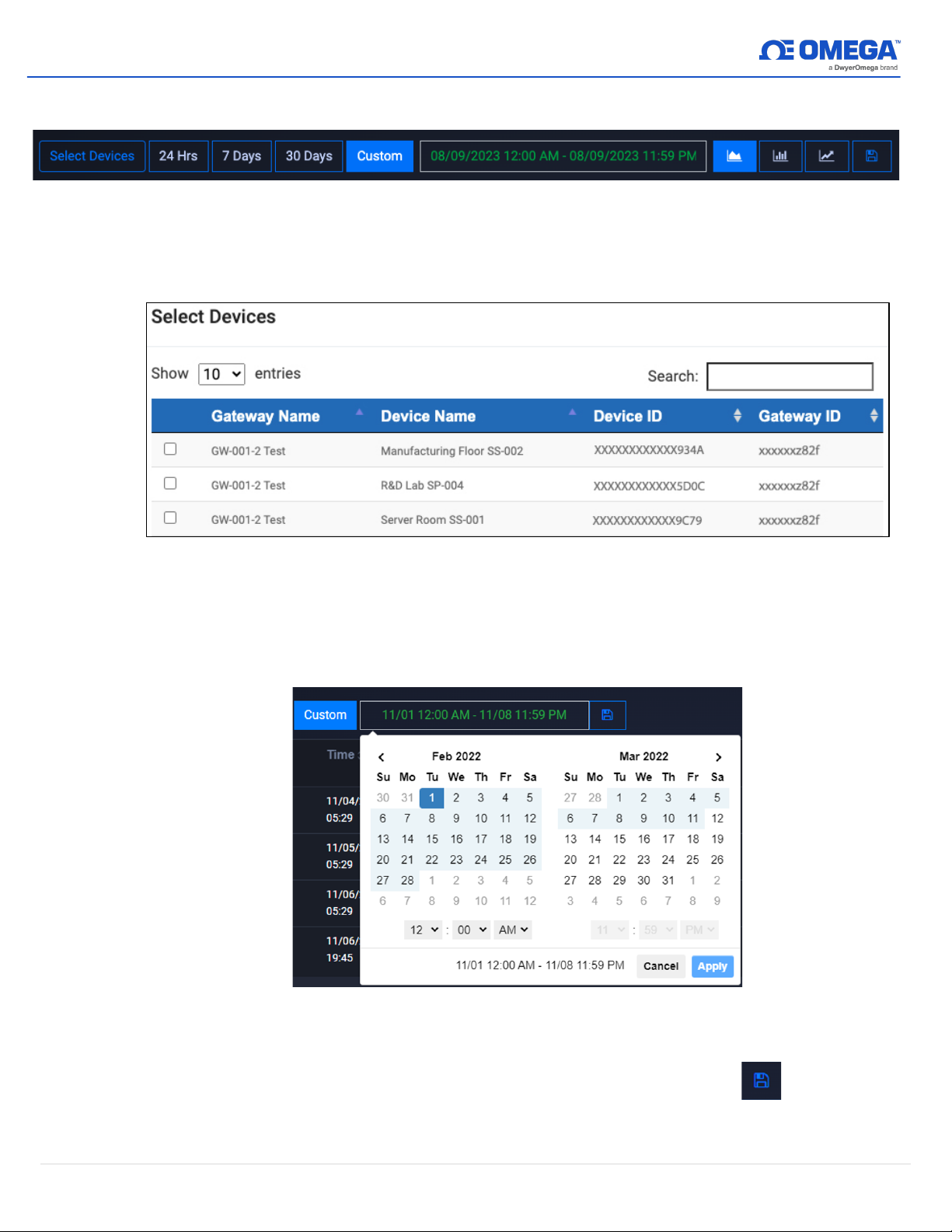
Users can begin to generate a
Figure 18: Historical Data Report parameters
Historical Data Report
by clicking the
Select Devices
button.
Users can then select the desired device(s) to add to the report by clicking the associated
OK
checkboxes. Click
to finalize the selection.
Figure 19: Historical Data Report Select Devices interface
Select a period or a range of dates
To specify the range of time the report will cover, users can select
Custom
date and time. Click
Apply
Figure 20: Custom date range calendar interface
to finalize the changes.
24 Hrs, 7 Days, 30 Days
, or
Save the Result/Export Chart Data
Users can save and export the generated data by clicking the save icon . A .csv file of
the data will be generated and the user will be prompted to download the file.
Graph Data Presentation
14 | M5800
Page 16
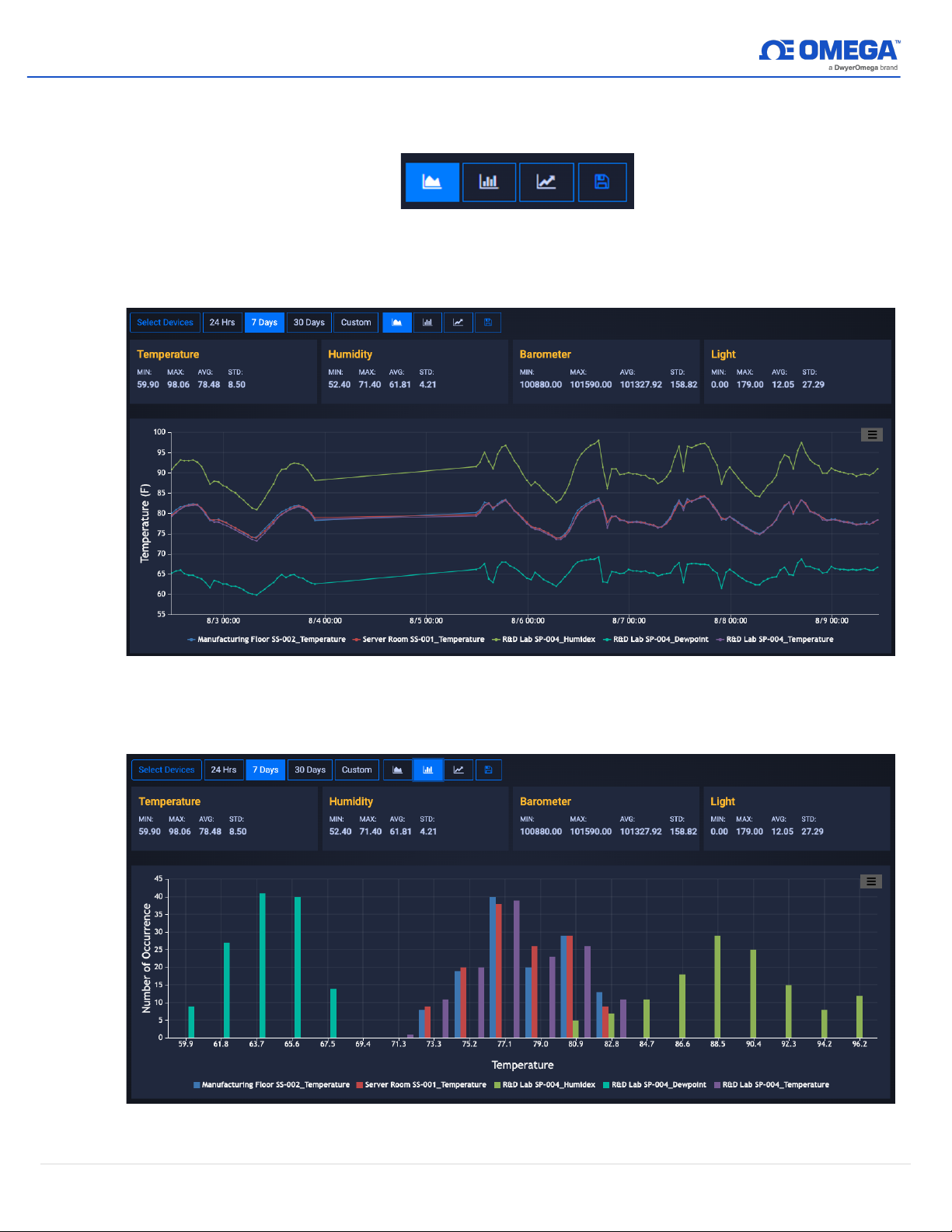
The Historian interface provides three methods of presenting graphed data:
Plot Histogram
Plot Prediction
, and
.
Figure 21: Graph data viewing options
Plot Time Series
Plot Time Series
,
Plot Histogram
Figure 22: Plot time series graph view
Figure 23: Plot Histogram graph view
15 | M5800
Page 17
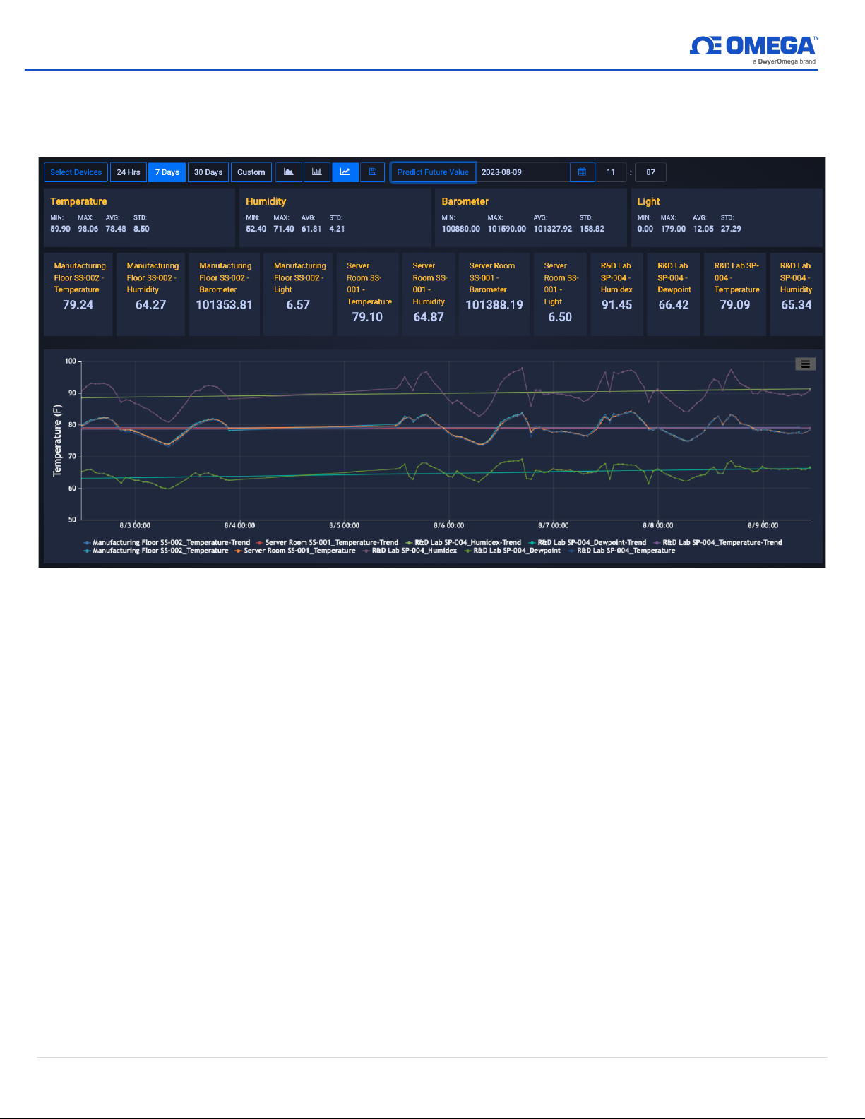
Plot Prediction
To utilize the
Plot Prediction
predict and click the
feature, enter the date and time of the value you would like to
Predict Future Values
button to display the data.
Figure 24: Plot Prediction graph view
16 | M5800
Page 18
3.3 System Settings
The System settings for the Omega Link Cloud allow you to customize your profile information, the
units of measure displayed, user access permission, subscription management, and include contact
information for technical support and feedback.
3.3.1 Profile
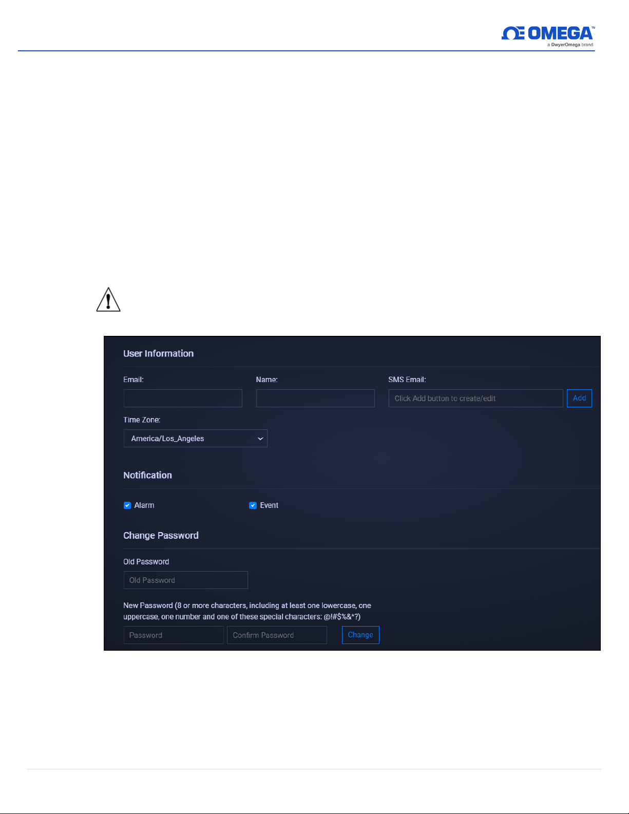
The Profile tab allows users to configure settings such as associated email addresses,
passwords, security questions, and notifications.
Using the email address associated with the account or by providing an SMS email address,
users can receive notifications directly whenever an alarm or event is triggered.
Passwords can be updated by entering the old password in the text box and then entering
and confirming the new password as directed on the webpage. Security questions can be
configured at the bottom of the Profile webpage.
Important:
Ensure the Notification checkboxes are properly marked according to the
type of notification alert the user would like to receive.
Figure 25: Omega Link Cloud Profile settings
17 | M5800
Page 19
3.3.2 Units
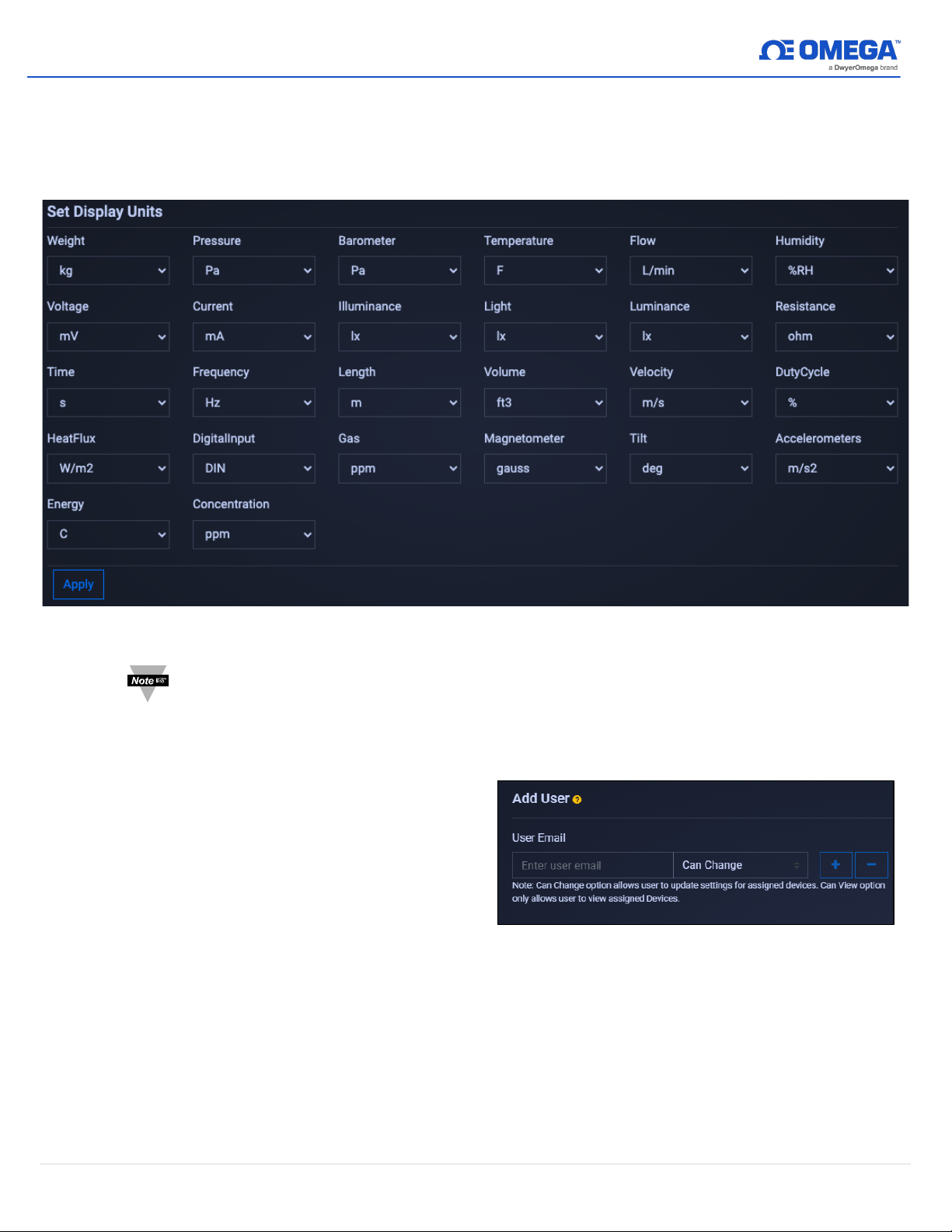
Figure 26: Omega Link Cloud local display units
Figure 27: Omega Link Cloud Add or Remove user access
The Units tab allows users to set their preferred units of measure as they appear on the
Omega Link Cloud. Changing the units here does not change the units of your sensing
devices. It only changes the unit of measure as it appears on the Omega Link Cloud.
Note
3.3.3 Users
The Users tab allows Administrator
Users to add organizational users via
email to the Omega Link Cloud account.
This provides them permission to view
or change the sensing device data
associated with the account. To add a
user, enter their email address in the
text box and choose
Can View
access.
: Changing the units of measurement only affects the readings displayed on the
Omega Link Cloud. Omega Link sensing devices interpret data according to the
International System of Units (SI).
Can Change
or
to grant access or restrict
18 | M5800
Page 20
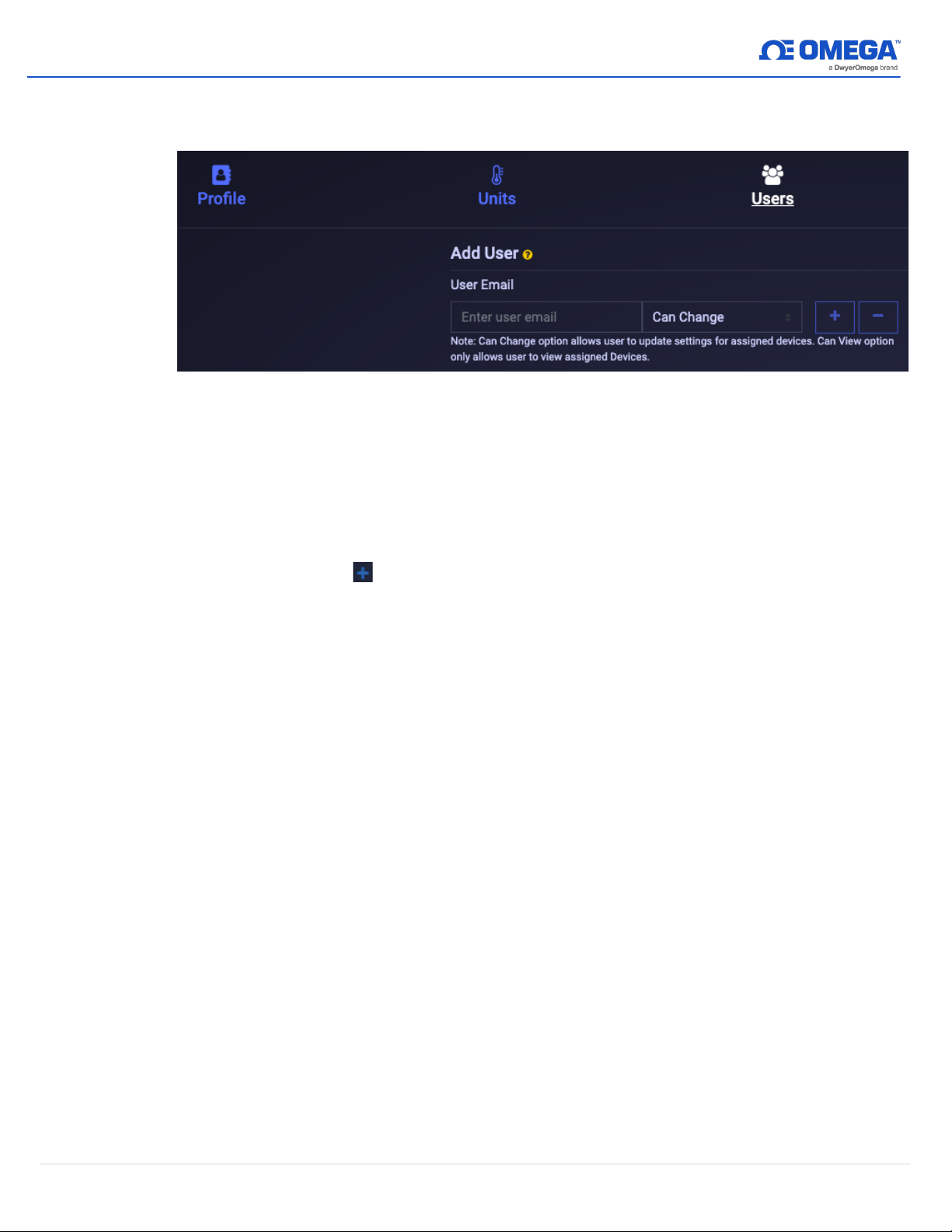
3.3.3.1 How to Add Organizational Users
To add organizational users to an Omega Link Cloud account, follow these steps:
Figure 28: Omega Link Cloud Users tab
Step 1:
Step 2:
Step 3:
Step 4:
3.3.4 Subscription
The Subscription tab shows your current subscription tier and provides a link to the Omega
website should you choose to upgrade your subscription plan. If you purchased the
subscription with a billing email different than your Omega Link Cloud account email, you
may link the two here.
3.3.5 Contact Us
The Contact Us tab provides an email address link for direct engineering technical support. It
also provides a text field for user feedback and comments.
On the Omega Link Cloud homepage, click on the
Users
. Enter the email address of the user you want to add.
SYSTEM
tab, and click on
Click the dropdown next to the email address text box and select the level of
access the new user will have:
Can Change
Can View
or
.
Click the icon to add the user. The email address of the new user will
appear on the
Existing Users
table.
Once the previous steps are complete, the new user will receive an email
prompting them to register an Omega Link Cloud account. If no email is
received within 10 minutes, the email may be in the user’s spam folder.
19 | M5800
Page 21
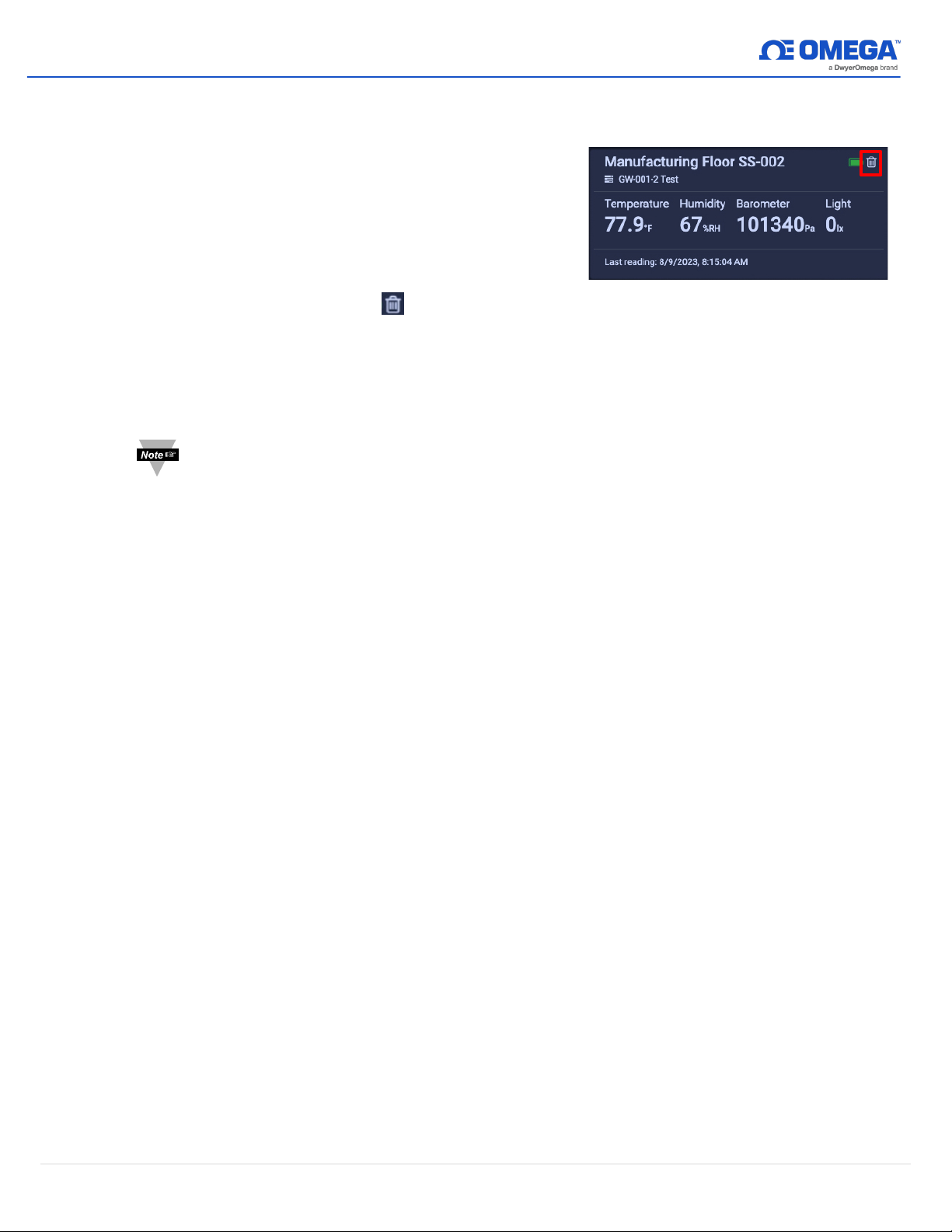
3.4 How to Remove a Paired Smart Sensor from a Gateway
Figure 29: Omega Link Cloud UI Smart Sensor
readings
To remove a paired Smart Sensor (such as the SS-001) from a registered Omega Link Gateway, follow
the steps below:
Step 1:
Log in to the Omega Link Cloud account associated
with the paired devices.
Step 2:
From the Omega Link Cloud device readings page,
identify the Smart Sensor that will be removed,
and click the Trash Can icon .
3.4.1 How to Move a Paired Smart Sensor to a Different Omega Link Gateway
To move a paired Smart Sensor (such as the SS-001) to a different Gateway, follow the steps
below:
Note:
When moving a paired Smart Sensor to a different Gateway, alarm, and event
thresholds may be triggered and notifications based on user preference may be
delivered. Notifications sent as a result of the re-pairing process may be
disregarded.
Step 1:
Navigate to the Omega Link Cloud account that is associated with the Smart Sensor
and remove the Smart Sensor from the account.
Step 2
: Ensure the unit is powered with either a USB connection or batteries. Press and hold
the Pairing Button on their Smart Sensor for 8 seconds so that the LED Status
Indicator blinks red to factory reset the device, then release the pairing button.
After the factory reset, the LED Status Indicator on the Smart Sensor will turn Amber/Orange
indicating the device is in pairing mode and is ready to be paired to a new Gateway.
20 | M5800
Page 22

WARRANTY/DISCLAIMER
OMEGA ENGINEERING, INC. warrants this unit to be free of defects in materials and workmanship for a
period of 13 months from date of purchase. OMEGA’s WARRANTY adds an additional one (1) month
grace period to the normal one (1) year product warranty to cover handling and shipping time. This
ensures that OMEGA’s customers receive maximum coverage on each product.
If the unit malfunctions, it must be returned to the factory for evaluation. OMEGA’s Customer Service
Department will issue an Authorized Return (AR) number immediately upon phone or written request.
Upon examination by OMEGA, if the unit is found to be defective, it will be repaired or replaced at no
charge. OMEGA’s WARRANTY does not apply to defects resulting from any action of the purchaser,
including but not limited to mishandling, improper interfacing, operation outside of design limits,
improper repair, or unauthorized modification. This WARRANTY is VOID if the unit shows evidence of
having been tampered with or shows evidence of having been damaged as a result of excessive corrosion;
or current, heat, moisture or vibration; improper specification; misapplication; misuse or other operating
conditions outside of OMEGA’s control. Components in which wear is not warranted, include but are not
limited to contact points, fuses, and triacs.
OMEGA is pleased to offer suggestions on the use of its various products. However,
OMEGA neither assumes responsibility for any omissions or errors nor assumes liability for
any damages that result from the use of its products in accordance with information provided
by OMEGA, either verbal or written. OMEGA warrants only that the parts manufactured by the
company will be as specified and free of defects. OMEGA MAKES NO OTHER WARRANTIES OR
REPRESENTATIONS OF ANY KIND WHATSOEVER, EXPRESSED OR IMPLIED, EXCEPT THAT OF
TITLE, AND ALL IMPLIED WARRANTIES INCLUDING ANY WARRANTY OF MERCHANTABILITY
AND FITNESS FOR A PARTICULAR PURPOSE ARE HEREBY DISCLAIMED. LIMITATION OF
LIABILITY: The remedies of purchaser set forth herein are exclusive, and the total liability of
OMEGA with respect to this order, whether based on contract, warranty, negligence,
indemnification, strict liability or otherwise, shall not exceed the purchase price of the
component upon which liability is based. In no event shall OMEGA be liable for
consequential, incidental or special damages.
CONDITIONS: Equipment sold by OMEGA is not intended to be used, nor shall it be used: (1) as a “Basic
Component” under 10 CFR 21 (NRC), used in or with any nuclear installation or activity; or (2) in medical
applications or used on humans. Should any Product(s) be used in or with any nuclear installation or
activity, medical application, used on humans, or misused in any way, OMEGA assumes no responsibility
as set forth in our basic WARRANTY/DISCLAIMER language, and, additionally, purchaser will indemnify
OMEGA and hold OMEGA harmless from any liability or damage whatsoever arising out of the use of the
Product(s) in such a manner.
RETURN REQUESTS/INQUIRIES
Direct all warranty and repair requests/inquiries to the OMEGA Customer Service Department.
BEFORE RETURNING ANY PRODUCT(S) TO OMEGA, PURCHASER MUST OBTAIN AN AUTHORIZED
RETURN (AR) NUMBER FROM OMEGA’S CUSTOMER SERVICE DEPARTMENT (IN ORDER TO AVOID
PROCESSING DELAYS). The assigned AR number should then be marked on the outside of the return
package and on any correspondence.
The purchaser is responsible for shipping charges, freight, insurance and proper packaging to prevent
breakage in transit.
FOR WARRANTY RETURNS, please have the
following information available BEFORE contacting
OMEGA:
1. Purchase Order number under which the product
was PURCHASED,
2. Model and serial number of the product under
warranty, and
3. Repair instructions and/or specific problems
relative to the product.
OMEGA’s policy is to make running changes, not model changes, whenever an improvement is possible. This affords
our customers the latest in technology and engineering.
OMEGA is a trademark of OMEGA ENGINEERING, INC.
© Copyright 2019 OMEGA ENGINEERING, INC. All rights reserved. This document may not be copied, photocopied,
reproduced, translated, or reduced to any electronic medium or machine-readable form, in whole or in part, without the
prior written consent of OMEGA ENGINEERING, INC.
FOR NON-WARRANTY REPAIRS,
OMEGA for current repair charges. Have
the following information available BEFORE
contacting OMEGA:
1. Purchase Order number to cover the COST
of the repair,
2. Model and serial number of the product, and
3. Repair instructions and/or specific problems
relative to the product.
consult
Page 23
Where Do I Find Everything I Need for
Process Measurement and Control?
OMEGA…Of Course!
Shop online at omega.com
TEMPERATURE
Thermocouple, RTD & Thermistor Probes, Connectors, Panels & Assemblies
Wire: Thermocouple, RTD & Thermistor
Calibrators & Ice Point References
Recorders, Controllers & Process Monitors
Infrared Pyrometers
PRESSURE, STRAIN AND FORCE
Transducers & Strain Gages
Load Cells & Pressure Gages
Displacement Transducers
Instrumentation & Accessories
FLOW/LEVEL
Rotameters, Gas Mass Flowmeters & Flow Computers
Air Velocity Indicators
Turbine/Paddlewheel Systems
Totalizers & Batch Controllers
pH/CONDUCTIVITY
pH Electrodes, Testers & Accessories
Benchtop/Laboratory Meters
Controllers, Calibrators, Simulators & Pumps
Industrial pH & Conductivity Equipment
DATA ACQUISITION
Communications-Based Acquisition Systems
Data Logging Systems
Wireless Sensors, Transmitters, & Receivers
Signal Conditioners
Data Acquisition Software
HEATERS
Heating Cable
Cartridge & Strip Heaters
Immersion & Band Heaters
Flexible Heaters
Laboratory Heaters
ENVIRONMENTAL
MONITORING AND CONTROL
Metering & Control Instrumentation
Refractometers
Pumps & Tubing
Air, Soil & Water Monitors
Industrial Water & Wastewater Treatment
pH, Conductivity & Dissolved Oxygen Instruments
5800/1123
M-
 Loading...