

Page 1

User’s Guide
Shop online at
omega.com
e-mail: [email protected]
For latest product manuals:
www.omegamanual.info
LDX-4
Page 2

omega.com [email protected]
Servicing North America:
U.S.A. Omega Engineering, Inc.
Headquarters: Toll-Free: 1-800-826-6342 (USA & Canada only)
Customer Service: 1-800-622-2378 (USA & Canada only)
Engineering Service: 1-800-872-9436 (USA & Canada only)
Tel: (203) 359-16 Fax: (203) 359-7700
e-mail: [email protected]
For Other Locations Visit omega.com/worldwide
Section Title Section Title
1.0 Index 4.6.1 Voltage Connections
2.0 Safety Information 4.6.2 Current Connections
3.0 Introduction 4.7 Using an EMC Cable Gland
3.1 LDX-4 Enhancements 5.0 Setting up the Transducer and LDX-4
4.0 Installation 5.1 Links Explained
4.1 Mounting 5.2 Basic Procedure
4.2 Operational Environment 5.3 Sensitivity and the X2, X4, DIV2
4.2.1 Residential, Commercial Links
& Light Industrial 6.0 Half-Bridge Version
Environments 7.0 Specications
4.2.2 Industrial Environments 7.1 Electrical
4.3 Electrical Connections 7.2 Mechanical and Connections
4.4 Connecting the Transducer 7.3 Environmental
4.5 Connecting the Power Supply 7.4 Notes
4.6 Connecting the Signal Out
The information contained in this document is believed to be correct, but OMEGA accepts no liability for any errors it contains,
and reserves the right to alter specifications without notice.
Page 3

2.0: Safety Information
Terms in this Manual
WARNING statements identify conditions or practices that could result in personal
injury or loss of life.
CAUTION statements identify conditions or practices that could result in damage
to the equipment or other property.
Symbols in this manual
This symbol indicates where applicable cautionary or other information is
to be found.
WARNINGS:
Do not operate in explosive atmosphere
To avoid explosion, do not operate this equipment in an explosive atmosphere.
Safety Critical Environments
This equipment is not intended for use in a safety critical environment.
CAUTION:
Low Voltage
This equipment operates at below the SELV and is therefore outside the scope of
the Low Voltage Directive.
This equipment is designed to work from a low voltage DC supply. Do not operate
thisequipmentoutsideofspecication.
CAUTION:
Electrostatic Discharge
This equipment is susceptible to ESD (Electrostatic Discharge) when being
installed or adjusted, or whenever the case cover is removed. To prevent ESD
related damage, handle the conditioning electronics by its case and do not touch
the connector pins. During installation, follow the guidelines below.
• Ensureallpowersuppliesareturnedo.
• If possible, wear an ESD strap connected to ground. If this is not possible,
discharge yourself by touching a metal part of the equipment into which the
conditioning electronics is being installed.
• Connectthetransducerandpowersupplieswiththepowerswitchedo.
• Ensure any tools used are discharged by contacting them against a metal part
of the equipment into which the conditioning electronics is being installed.
• Duringsettingupoftheconditioningelectronics,makelinkconguration
changeswiththepowersupplyturnedo.Avoidtouchinganyothercomponents.
• Makethenalgainandosetpotentiometeradjustments,withpowerapplied, using an appropriate potentiometer adjustment tool or a small insulated
screwdriver.
Page 4
3.0: Introduction
The LDX-4 MK2 is a development of the original LDX-4. It is a compact conditioning module powered from a single DC supply. Adjustable gain and zero controls
are provided for use with the complete range of Omega transducers. The unit is
of robust construction, housed in a die cast aluminium box providing a substantial
degree of mechanical protection.
The LDX-4 MK2 incorporates its own voltage regulation for operation from 10-30
VDC and can provide outputs of up to
±10 V together with ±20 mA.
3.1: LDX-4 Enhancements
TheLDX-4MK2hasbeendesignedasaform,tandfunctionreplacementforthe
original LDX-4, but with several enhancements.
• Wider gain range, allowing ALL Omega transducers to be connected without
the need for attenuation resistors.
• Up to ±10 VDC and ±20 mA are available for all gain settings.
• Fixedandvariableosetsmakesettingofuni-polaroutputeasier.
• Gainandosetadjustmentarefullyindependent.
• Selectable transducer excitation frequency.
• Selectable transducer load resistances.
• Selection between forward and reverse connection.
• Fully CE Compliant.
• Half-Bridge transducers can now be accommodated with simple plug wiring
changes.*
* For half-bridge only variant see section 6.0.
4.0: Installation
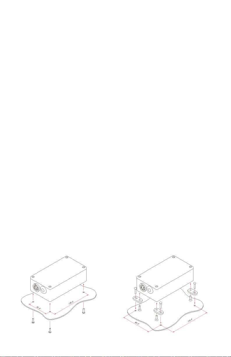
4.1: Mounting
The LDX-4 may be mounted in a variety of ways and in any attitude. Ensure that
there is enough space for the cover to be removed to allow for internal adjustments. Space should also be allowed for the transducer connector, EMC glands (if
tted)andcabling.ItisrecommendedthattheLDX-4casebeconnectedtoearth
or chassis. This earth connection is not a safety earth, but is part of the overall
electrical screening scheme.
Underside Mounting Top-Side Mounting
Note: If replacing LDX-4
MKIaretrotmountingkit
is available if repositioning
holes is not possible.
Page 5

4.0: Installation (continued)
4.2: Operational Environment
This section discusses the type of installation required depending on the electrical
environment.
4.2.1: Residential, Commercial and Light Industrial Environments
Typically,thiswillbeanoce,laboratoryorindustrialenvironmentwherethereisno
equipment likely to produce high levels of electrical interference, such as welders or
machine tools.
Connectionsmaybemadeusingtwisted,unscreenedwire.Thisisacosteective
option and will give good performance in this environment.
Standard equipment wire such as 7/0.2 (24AWG) can be twisted together as required. Standard data cable such as generic CAT5 UTP will also give good performance.
4.2.2: Industrial Environments
Typically, this will be an industrial environment where there is equipment likely to
produce high levels of electrical interference, such as welders, machine tools, cutting and stamping machines.
Connections should be made using screened cable. Braided or foil screened cables
may be used. The cable screen should be connected to the LDX-4 case at cable
entry point. The case of the LDX-4 should be connected to a local ground. An EMC
cable gland is recommended. This is supplied with the LDX-4.
When selecting the type of wire or cable to be used, consider the following parameters:
- Screening.
- Conductor size (resistance).
- Mechanicalaspectssuchasexibilityandrobustness.
This is not a complete list. Installations may require other special cable characteristics.
4.3: Electrical Connections
The LDX-4 requires three connections.
1. Transducer.
2. Power Supply.
3. Output Signal, Voltage or Current.
A small hole should be made in the grommet prior to passing the wires through. If
a screened cable is to be used, an EMC cable gland is recommended (see section
4.7).
Page 6
4.3: Electrical Connections (continued)
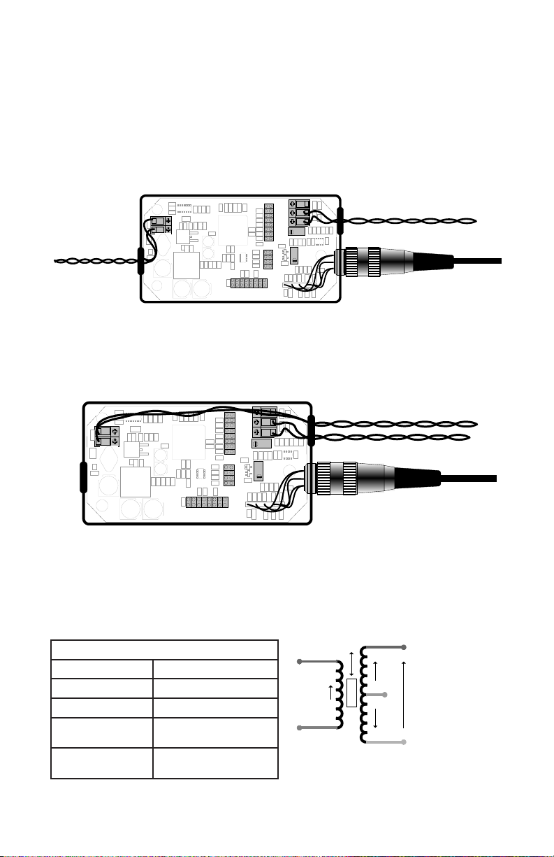
For best performance in electrically noisy environments, the case of the LDX-4
should be connected to a local earth. This can be achieved via the mounting
bracket. This earth connection is not a safety earth, but is part of the overall electrical screening scheme.
ThewiringlayoutarrangementsaresimilarforLDX-4ttedwithEMCglandsand
screened cable.
Separate Power Supply and Signal Out wires
LO
HI
P ow er S uppl y
1 2 3 4 5 6 (7 )
0V +V E
(X4 )
X2
COA R SE G AIN
V OU T 0 V I O UT
FINE G AIN
-VE
+VE
5V
FINE O FF SE T
2.5V
COA RS E
OFF SE T
DIV 2
- -
G BK W B R
10K
¦
2K
|F|
- -
R
¦
S ig nal O ut
Tra nsduce r
Power Supply and Signal Out wires from one end only
Connections to the power supply should be routed to one side as shown. This
helps to reduce interference between power supply wires and the more sensitive
parts of the circuitry.
LO
HI
1 2 3 4 5 6 (7 )
0V +V E
DIV 2
(X4 )
X2
CO AR SE G AIN
V O UT 0 V I O U T
FIN E G AI N
-VE
+VE
5V
FIN E O FF SE T
2.5V
COA RS E
OFF SE T
G BK W B R
10K
¦
2K
|F|
- -
- -
R
¦
P o w er S up p ly
S ig na l O ut
Tra ns d u c e r
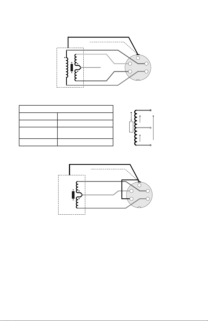
4.4: Connecting the Transducer
Transducersttedwitha5-pinDINplugaresimplyscrewedintothecase
mountedsocket.Transducersnotttedwithaplugshouldbewiredtotheplug
supplied. For the half-bridge only variant see section 6.0.
CO R E
G ree n
V
A
Ye llow
Ce ntr e T ap
V
B
W hit e
Me as ure d
Ou tpu t
V
O
LVDT Electrical Connections
Red and Blue Energizing
Green and White Signal
Yellow Secondary Centre Tap
Red and White
Black
In Phase for Inward
Displacement
Transducer Body
Ground
Pr ima ry
Re d
Bl ue
V
e
Page 7
4.4: Connecting the Transducer (continued)
St an da rd LV DT Ga ug in g P ro be Plu g Co nn ec tio ns
LV DT
+
-
Ca se
No te 1: + in di cat es inw ar d m ov em en t o f th e t ip.
No te 2: Th e t ran sd uce r b od y m ay be d isco nn ec ted fr om th e c ab le s cre en by
cu ttin g t he bla ck wir e i nsi de the co nn ec tor
Bl ack
Ca ble S cre en
Bl ue
W hit e
Ye llo w
Gr ee n
Re d
Half-Bridge Electrical Connections
Red and Blue Energizing
Yellow Signal
Red and Yellow
In Phase for Inward Displacement
Black Transducer Body Ground
St an da rd Ha lf-B rid ge G au gin g P ro be Pl ug Co nn ec tio ns
Ha lf- Bri dge
+
-
Ca se
No te 1: + in di cat es inw ar d m ov em en t o f th e t ip.
No te 2: Th e t ran sd uce r b od y m ay be d isco nn ec ted fr om th e c ab le s cre en by
cu ttin g t he bla ck wir e i nsi de the co nn ec tor
Bl ack
Ca ble S cre en
Bl ue
Ye llo w
Re d
4
5
LI NK
Ca se
3
Pl ug vie w
int o p ins
V
A
CO R E
Ce ntr e T ap
V
B
Ca se
3
4 2
5
Pl ug vie w
int o p ins
2
1
Bl ue
Ye llow
1
Re d
V
O
4.5: Connecting the Power Supply
The LDX-4 requires a dc power supply in the range 10-30 V. A fully regulated
supply is not required, but the voltage at the input to the LDX-4 must remain
withinspecication.Ideally,the0Vatthepowersupplyshouldnotbeconnected
to earth or the chassis, as this would result in ground loops being formed. The 0
V supply, 0 V signal and case are all internally connected together at the LDX-4.
4.6: Connecting the Signal Out
The output signal may be voltage or current.
Page 8
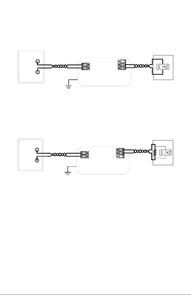
4.6.1: Voltage Connections
Voltage can easily be monitored using a variety of instrumentation such as
voltmeters. Voltage drops along wires contribute to measurement errors, so care
must be taken when using long cable lengths (100 m for example). High impedance instruments are more prone to interference.
Po w er S up pl y
+ 10 -30 V
0V
+V E
0V
Io ut
Vo ut
0V
Pr oce ss M oni tor
+
V ol tag e
The signal 0 V should always be used as reference. If power supply 0 V is used,
then error voltages may be introduced.
4.6.2: Current Connections
Current output requires the use of purposely designed current input instrumentation. Current output is more suitable for transmitting over longer distances because current is not lost due to wiring resistance. Additionally, with a low impedance, a current loop is less likely to pick up noise.
Po w er S up pl y
+ 10 -30 V
0V
+V E
0V
Io ut
Vo ut
0V
Pr oce ss M oni tor
+
-
C urr en t
The total loop resistance (resistance of measuring equipment and wiring) must
notexceedspecication.
Note: The LDX-4 is not loop-powered, so a power supply must not be used in-line
with the current output.
Page 9
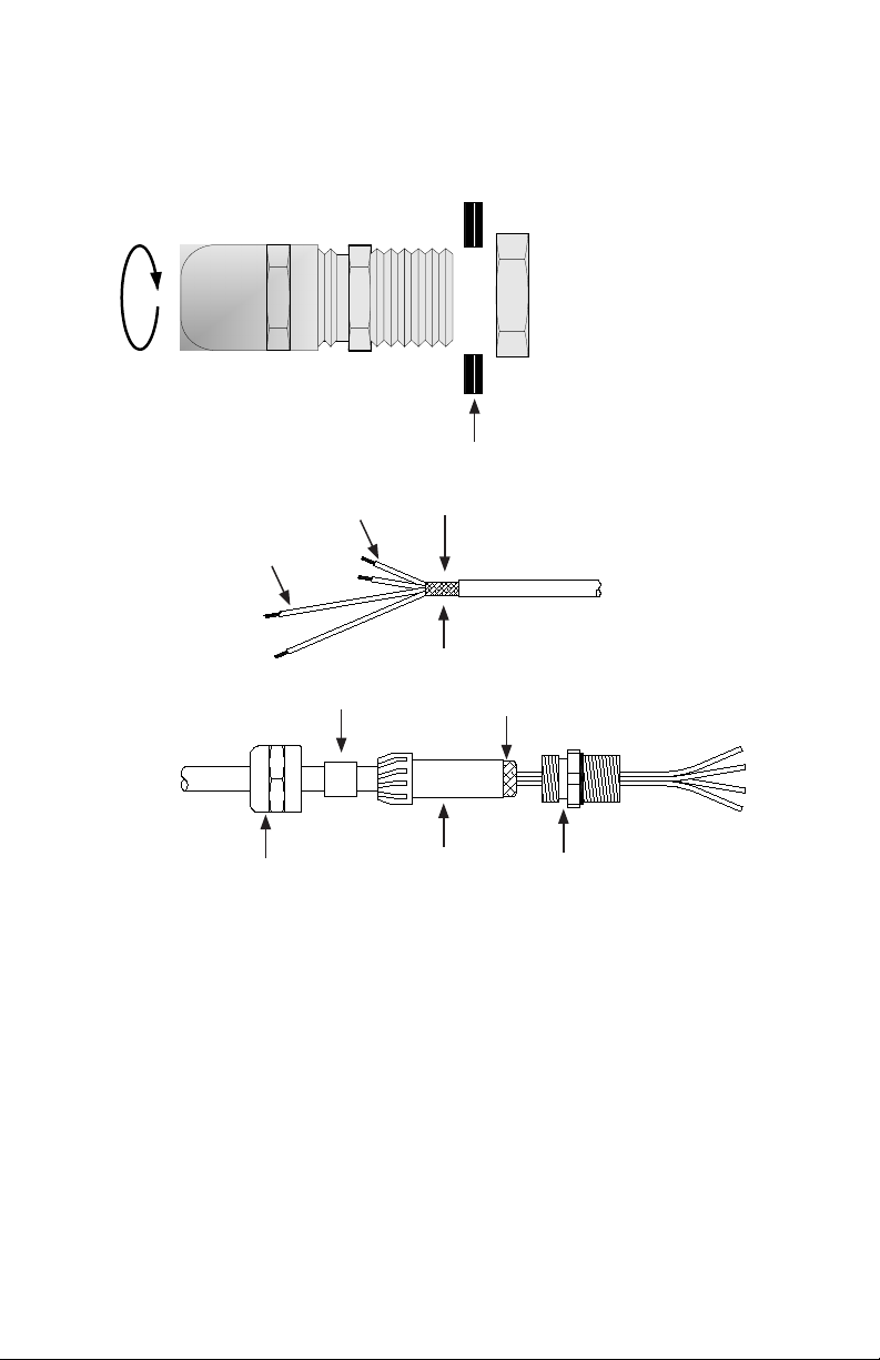
4.7: Using an EMC Cable Gland
To ensure the cable screen is properly connected to the LDX-4 case, an EMC
cable gland should be used. This is supplied as an optional extra. The diagrams
belowassumeasingle4-waycableisbeingused.Removethegrommetandt
the cable gland as shown below.
Rotate Gland
Body to Tighten
Case Wall
30 mm
125 mm
Sealing Ring
Dome Nut
10-15 mm
Screen
Rolled Back Screen
Plastic
Insert
Gland Body
• Prepare cable as shown.
• Slide the Dome nut, sealing ring and plastic insert over cable.
• Fold and roll the screen back over itself to form a lump.
• Push cable into gland body followed by the plastic insert (ensure anti-rotation
slots engage), sealing ring and Dome nut.
• Ensure all components are properly seated before tightening the dome nut.
Page 10
5.0: Setting up the Transducer and LDX-4
The LDX-4 may be set-up with output signals anywhere within a ±10 VDC or ±20
mA range. Typical outputs are
±10 VDC, ±5 VDC, 0-10 VDC and 4-20 mA. These procedures apply to voltage
and current output.
Voltage and current output are available at the same time, although they cannot be individually adjusted. Either voltage or current should be chosen as the
calibration reference.
All outputs use 0 V signal as the signal reference.
A list of standard link settings is available, see section 5.2.
CAUTION:
During installation and adjustment, the top of the enclosure has to be
removed for access to user adjustments.
At this time, standard ESD handling precautions for electronic equipment should
be followed.
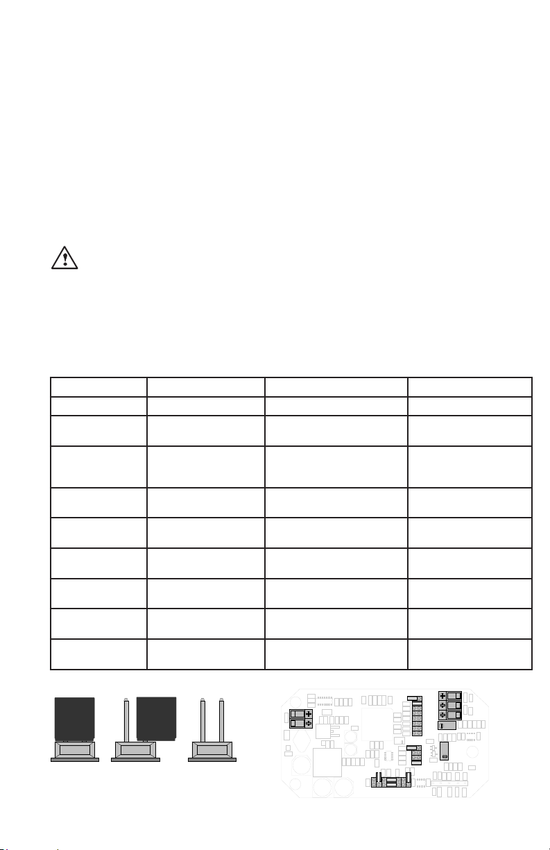
5.1: Option Links - Explained
The table below and subsequent diagrams explain the link functions and show
the factory setting.
Link Description Options Standard Setting
Course Gain Sets the basic gain 1 link on Positron 1 to 6 Link ON Position 1
Fine Gain Adjustment between
course gain ranges
CourseOset Shifts the output by a
xedamount
FineOset Fine trim around any
xedoset
(7) Null Used during set-up to
null output
Freq. Selects transducer
primary frequency
Input Resistance Sets transducer
secondary load
Polarity (FR) Enables output signal
direction change
Input Gain Input Gain of x1, x2,
x4 or divide 2
Potentiometer Adjustment Mid Position
Link ON -VE or +VE and
Link ON 5V or 10V
Nooset-Links
Parked
Nooset-LinkParked
Potentiometer Adjustment Mid Position
ON, OFF OFF
Lo - ON, Hi - Parked Hi Freq. - Link Parked
100 KW Parked, 10 KW -
100 KW - Link Parked
ON, 2 KW - ON
2 Links across Forward or
F Position - 2 Link ON
Reverse
X1 - Parked, X2 - ON, X4 -
Link parked on X2
ON, DIV2 - ON
(OF F)
FRE Q
(ON )
HI
LO
1 2 3 4 5 6 (7 )
0V +V E
POW E R
Li nk ON Lin k P AR KE D
Li nk OF F
DIV 2
X2
X4
- -
CO AR SE GA IN
NUL L
-VE
+VE
5V
10V
COA RS E
OFF SE T
G BK W R B
10K
¦
2K
|F|
- -
R
¦
V O UT 0 V I O UT
FINE G AIN
OUT PU T
FIN E O FF SE T
Page 11
5.0: Setting up the Transducer and LDX-4 m(continued)
✓
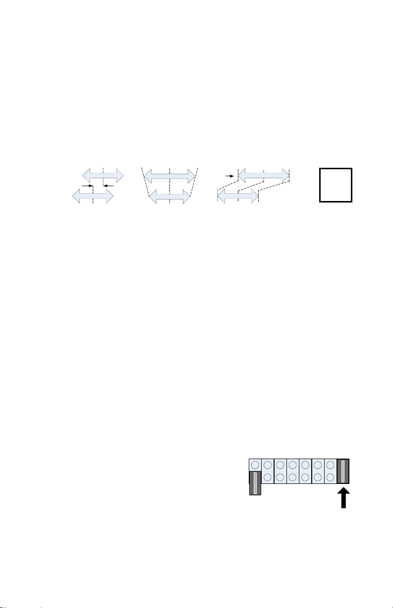
5.2: Basic Procedure
To set-up the LDX-4, some basic steps should be followed.
The following steps describe a typical setting procedure and applies to most applications. Other procedures may be used as appropriate.
Step 1 Step 2 Step 3 Step 4 Step 5
Set-up AlignLDX-4 SetLDX-4 AddOset Final
LDX- 4 and and if Required Checks
links Transducer Null Transducer Range
V/V
±V
Hz
KW
Ze ro
el ect ro nic s
tra ns du ce r
Nu ll
-5 V +5 V
Ze ro
el ect ro nic s
tra ns du ce r
Nu ll
Sh ift
ze ro
tra ns du ce r
+5 V0V +1 0V
el ect ro nic s
Nu ll
For a bi-polar output i.e. ±10 VDC or ±20 mA, follow steps 1 to 3.
For a uni-polar output i.e. 0-10 V, 0-20 mA or 4-20 mA, follow steps 1 to 4.
Ineithercase,step5(nalchecks)shouldbefollowedonthecompletionofthe
set-up.
5.2: Basic Procedure
STEP 1 - Set-up LDX-4 Links
If the transducer characteristics are known, set the frequency and input resistance links as required. If the transducer characteristics are not known, the
standard link settings should be used.
If your transducer is known to be outside of the standard sensitivity range, the X2
or DIV2 links will have to be used. See section 5.3.
STEP 2 - Align LDX-4 Null and Transducer Null
AnyelectricalosetintheLDX-4isremoved.Thetransducerpositionisadjusted
so that transducer and LDX-4 nulls are aligned.
Null the LDX-4
1. Put the Gain link on position (7) as
shown.Thisallowsanyelectronicsoset
in the output stage to be removed.
2. AdjusttheFineOsetcontroltogiveas
FR E Q
LO
(O N)
1 2 3 4 5 6 (7)
N U LL
near to zero output as practical.
Null the transducer.
1. Replace the Gain link to the original position.
H I
(O FF)
2. Adjust the position of the transducer to
give as near to zero output as practical. This is the centre of the mechanical
range.
Ifthetransducercannotbecenteredforpracticalreasonsanosetwillremain
withinthesystem.TheremaybenoticeableinteractionbetweenGainandOset
adjustment. This does not prevent the LDX-4 being set-up, however several itera-
tionsmayberequiredwhenadjustingGainandOset.Pleasecontactyoursupplier
if guidance is required.
Page 12

5.2: Basic Procedure
10K
2K
- -
¦
R
¦
|F|
- -
DIV 2
X2
(X4)
10K
2K
- -
¦
R
¦
|F|
- -
DIV 2
X2
(X4)
STEP 3 - Setting Bi-Polar Full-scale Output
1. Move the transducer to the position where maximum LDX-4 output is required.
2. If the polarity of the output is wrong, move the Polarity (FR) links to the R position (see link diagram).
3. Move the RANGE link between 1 and 6 until the LDX-4 output is near the
required value.
4. Adjust the Fine Gain control to give the required output.
5. A bi-polar output has now been set, proceed to step 5. If a uni-polar output is
required, proceed to step 4.
Example: ±10 VDC is required from a ±1 mm transducer. Set the transducer to +1
mm and set the output to 10 V.
If your transducer is known to be outside of the standard sensitivity range, the X2,
X4 or DIV2 links will have to be used. See section 5.3.
STEP4-SettingUni-polarFull-ScaleOutput(addinganoset)
1. Move the transducer to the null position. LDX-4 output will be 0 V or 0 mA.
2. Applyosetusingthe+VE,-VE,5Vand10VlinksandthenadjusttheFine
Osetcontroltosettheosetprecisely.
3. Performnalchecks,step5.
Example: 0-10 V is required for a ±1 mm transducer. Set the transducer to give ±5
Voverthefullrangeandthen,withthetransduceratnull,add+5Voset.Adjust
theFineOsetcontroltogive5V.Whenthetransducerismovedtothe
+1 mm position, the output will be +10 V.
Example: 4-20 mA is required for a ±1 mm transducer. Set the transducer to give
±8 mA over the full range and then, with the transducer at null, add +2.5 V (approx.
5mA)oset.AdjusttheFineOsetcontroltogive+12mA.Whenthetransduceris
moved to the +1 mm position, the output will be +20 mA.
STEP 5 - Final Checks
Ensure that the calibration is correct by moving the transducer across the required
mechanical range, checking calibration points. Fine adjustment can be made if
required.
It may only be possible to set the output accurately at the two calibration points.
This is due to non-linearity within the transducer.
5.3: Transducer Sensitivity and the X2, X4, DIV2 Link
The LDX-4 compensates for changes in primary signal amplitude by producing an
internal error signal that is the ratio between the primary and secondary signals. If
the transducer output signal is too high or too low, errors may occur that can degrade the performance of the LDX-4 / transducer combination. For these transducers, the X2, X4 or DIV2 input gain link must be used.
Page 13
5.3: Transducer Sensitivity and the X2, X4, DIV2 Link
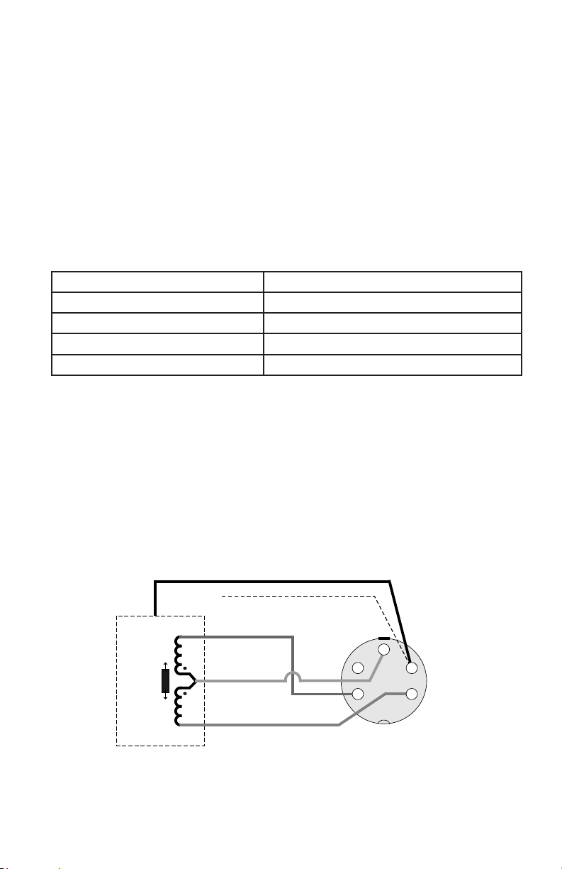
Red
Blue
Yellow
+
-
Case
Half-Bridge
Cable Screen
Black
Case
Plug view
into pins
Standard Half-Bridge Gauging Probe Plug Connections
Note 1: + indicates inward movement of the tip.
Note 2: The transducer body may be disconnected from the cable screen by
cutting the black wire inside the connector
4
1
2
5
3
Transducer Full Range Output
In general, transducer sensitivity is quoted as mV/V/mm
Where: mV is the output of the transducer
V is the primary voltage
mm is the mechanical position of the transducer from null
(usually mid mechanical range).
To get the transducer Full Range Output, multiply all three together.
Example: GP911-1 sensitivity is 210 mV/V/mm
GP911-1 range is ±1 mm
LDX-4 primary voltage 3 V
Transducer Full Range Output = 210 x 3 x 1 = 630 mV (0.63 V)
Set the X2, X4, DIV2 link as shown in the table below.
Transducer Full Range Output Input Gain Link Setting
400 mV FR to 2500 mV FR Standard Range - Link Parked on X2
2500 mV FR to 5000 mV FR High Transducer Output - Link ON DIV2
150 mV FR to 400 mV FR Low Transducer Output - Link ON X2
55 mV FR to 150 mV FR Very Low Transducer Output - Link ON X4
6.0: Half-Bridge only Variant
This is a half-bridge optimized variant of the standard product. The excitation fre-
quencyishigher(seespecication)andthetransducerinputconnectoriswiredto
accept half-bridge transducers with standard connections.
6.1: Connecting the transducer
The5-pinDINplugisscrewedintothecasemountedsocket.Transducersnottted
with a plug should be wired to the plug supplied. LVDT transducers cannot be connected to this input.
Page 14
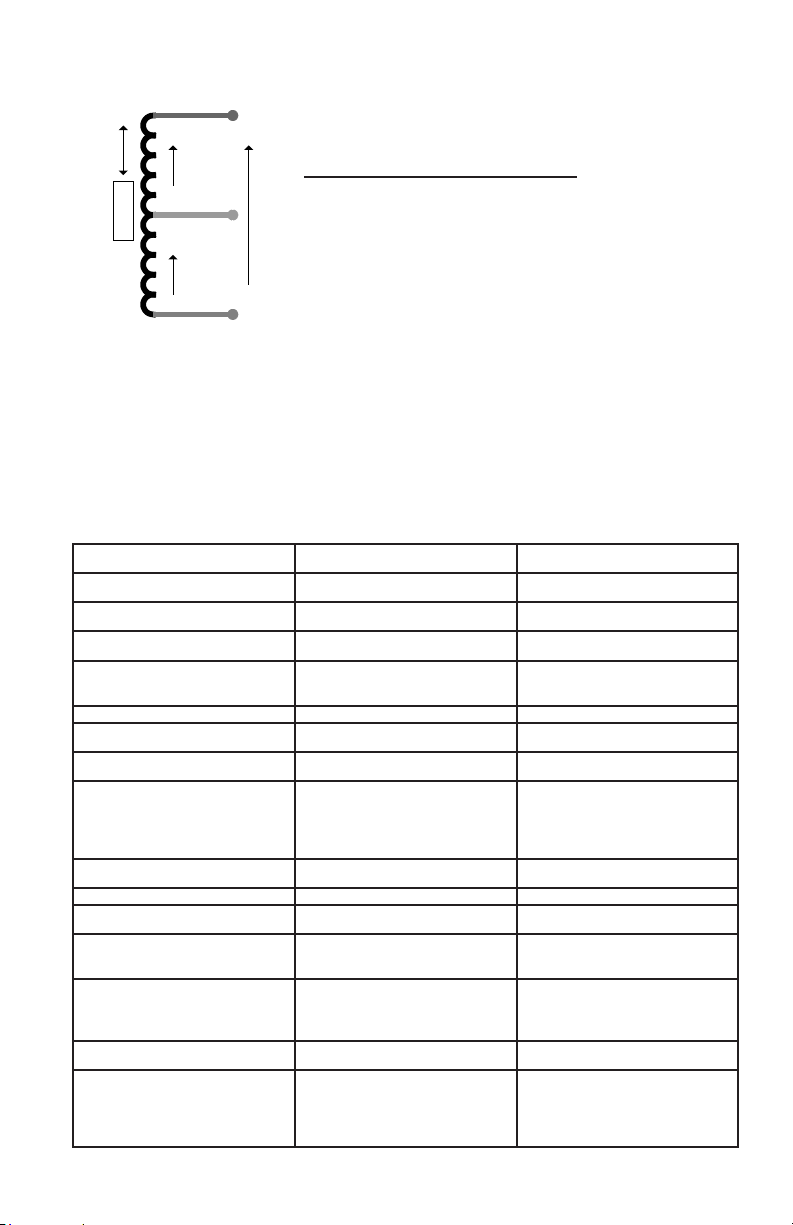
6.1: Connecting the transducer
Blu e
V
C O RE
A
C ent re Tap
V
B
Yello w
R ed
Half-Bridge Electrical Connections
Red and Blue Energizing
Yellow Signal
Red and Yellow In Phase for Inward Displacement
Black Transducer Body Ground
V
O
6.2: Setting up the Half-Bridge Transducer
The setting up procedure is the same as LVDT transducers. See section 5. The
sensitivity of half-bridge transducers is generally lower than for LVDT types, the x2
and x4 gain position may have to be used.
7.0:Specications
7.1: Electrical
Parameter Value Comments
Power Supply
Typical Voltage / Current 24 VDC at 55 mA
Voltage Range 10 to 30 VDC
Current Range 140 mA at 10 V to 50 mA
at 30 V
Transducer Excitation
Energizing Voltage 3 Vrms nominal see note 1
Energizing Frequency 2.5 kHz (Lo) or 5 kHz (Hi)
nominal
link selectable
Half-Bridge version only
10 kHz (Lo) or 13 kHz
(Hi)
Energizing Current 30 mA max.
Transducer Signal Input
Input Signal Range
Standard
Special DIV2 2500 to 500 mV FR
400 to 2500 mV FR 6 gain ranges (applies to
LVDT only)
see note 2
x2 150 to 400 mV FR
x4 55 to 150 mV FR
Input Load Resistance 2, 10, 10 KW link selectable
Options Forward and Reverse
LVDT Input
Half-Bridge Input
link selectable
standard
special plug wiring or
half-bridge version only
Page 15

7.1: Electrical
Parameter Value Comments
Signal Output
Output Voltage Range up to ±10 VDC into 1 KW see notes 3 and 4
Output Residual Noise <1 mVrms
Output Current up to ±20 mA into 150 W
load
see note 5
OutputOsetCoarse ±5 VDC (approx 10 mA)
Fine ±2.8 VDC (approx 5.6
TemperatureCoecient
Gain
TemperatureCoecient
Oset
Warm-Up 15 minutes recom-
Linearity <0.1% FRO
Bandwidth (-3dB) 500 Hz typical
Protection (see note 6)
Power Supply Reverse connection
Inputs and Outputs Short circuit protected
Certication(seenote7)
Immunity BS EN61000-6-2:2001 Immunity for Industrial
Emissions BS EN61000-6-3:2001 Emission for Residential,
xed
±10 VDC (approx 20 mA)
xed
mA)
<0.01% FRO/°C
<0.01% FRO/°C
mended
protected
Transient and ESD Protected
link selectable
link selectable
Variable(addstoxed
osets)
Environments
commercial and
light-industrial environments
7.2: Mechanical and Connections
Parameter Value Comments
Transducer 5-pin circular DIN
Power Supply Internal Terminal Block
Output Signal Internal Terminal Block
Enclosure - Size 120 x 65 x 40 mm Excluding connectors
Weight 300 g (0.66 lbs) approx.
Material of Case Die-Cast Zinc Alloy (painted)
Page 16

7.3: Environmental
Parameter Value Comments
Operating Temperature Range 0 - 60°C
Storage Temperature Range -20 - 85°C see notes 3 and 4
IP Rating IP40
7.4: Notes
1. Primaryvoltageabsolutevalueanddriftisnotspecied.TheLDX-4usesratiometric techniques to compensate for primary voltage drift.
2. ThewayinwhichtheLDX-4functionsmeansaspecialcongurationmustbe
used for transducers outside of the standard range. This is selectable by links.
The majority of Omega LVDT transducers are within the standard range. See
section 5.
3. LDX-4 can drive into a 1 KWloadbutthisoersnoadvantage.10-100KW is
recommended.
4. Output voltage range can be adjusted as required anywhere within this range
byusingacombinationofgainandoset,forexample.±10VDC,±5VDC,0-5
VDC, 0-10 VDC, 4-20 mA.
5. Current output may be used at the same time as voltage output. Calibration of
voltage and current cannot be individually adjusted.
6. Protection applies to the product when fully installed according to the user
manual. During installation the top of the enclosure has to be removed for access to user adjustments. At this time standard ESD handling precautions for
electronic equipment should be followed.
7. The LDX-4 complies with the toughest electrical emissions and immunity
regulations. Compliance requires installation according to the user manual.
Compliance does not guarantee performance as the installation environment
maybeoutsideoftestspecicationlimits.TheexibilityofLDX-4meansitcan
be installed in a variety of ways according to user requirements. Simple installations with short non-screened cables will meet the lesser light-industrial immunity regulations. Heavy industrial installations, especially with longer cables,
will need more careful installation with screened cables.
Page 17

Page 18

Page 19

WARRANTY/DISCLAIMER
OMEGA ENGINEERING, INC. warrants this unit to be free of defects in materials and workmanship for
a period of 13 months from date of purchase. OMEGA’s WARRANTY adds an additional one (1) month
grace period to the normal one (1) year product warranty to cover handling and shipping time. This
ensures that OMEGA’s customers receive maximum coverage on each product.
If the unit malfunctions, it must be returned to the factory for evaluation. OMEGA’s Customer Service
Department will issue an Authorized Return (AR) number immediately upon phone or written request.
Upon examination by OMEGA, if the unit is found to be defective, it will be repaired or replaced at no
charge. OMEGA’s WARRANTY does not apply to defects resulting from any action of the purchaser,
including but not limited to mishandling, improper interfacing, operation outside of design limits,
improper repair, or unauthorized modification. This WARRANTY is VOID if the unit shows evidence
of having been tampered with or shows evidence of having been damaged as a result of excessive
corrosion; or current, heat, moisture or vibration; improper specification; misapplication; misuse or
other operating conditions outside of OMEGA’s control. Components in which wear is not warranted,
include but are not limited to contact points, fuses, and triacs.
OMEGA is pleased to offer suggestions on the use of its various products. However,
OMEGA neither assumes responsibility for any omissions or errors nor assumes liability for any
damages that result from the use of its products in accordance with information provided by OMEGA,
either verbal or written. OMEGA warrants only that the parts manufactured by the company will be as
specified and free of defects. OMEGA MAKES NO OTHER WARRANTIES OR REPRESENTATIONS
OF ANY KIND WHATSOEVER, EXPRESSED OR IMPLIED, EXCEPT THAT OF TITLE, AND ALL
IMPLIED WARRANTIES INCLUDING ANY WARRANTY OF MERCHANTABILITY AND FITNESS
FOR A PARTICULAR PURPOSE ARE HEREBY DISCLAIMED. LIMITATION OF LIABILITY: The
remedies of purchaser set forth herein are exclusive, and the total liability of OMEGA with respect to
this order, whether based on contract, warranty, negligence, indemnification, strict liability or otherwise,
shall not exceed the purchase price of the component upon which liability is based. In no event shall
OMEGA be liable for consequential, incidental or special damages.
CONDITIONS: Equipment sold by OMEGA is not intended to be used, nor shall it be used: (1) as
a “Basic Component” under 10 CFR 21 (NRC), used in or with any nuclear installation or activity; or
(2) in medical applications or used on humans. Should any Product(s) be used in or with any nuclear
installation or activity, medical application, used on humans, or misused in any way, OMEGA assumes
no responsibility as set forth in our basic WARRANTY / DISCLAIMER language, and, additionally,
purchaser will indemnify OMEGA and hold OMEGA harmless from any liability or damage whatsoever
arising out of the use of the Product(s) in such a manner.
Direct all warranty and repair requests/inquiries to the OMEGA Customer Service Department.
RETURN REQUESTS/INQUIRIES
BEFORE RETURNING ANY PRODUCT(S) TO OMEGA, PURCHASER MUST OBTAIN AN
AUTHORIZED RETURN (AR) NUMBER FROM OMEGA’S CUSTOMER SERVICE DEPARTMENT (IN
ORDER TO AVOID PROCESSING DELAYS). The assigned AR number should then be marked on the
outside of the return package and on any correspondence.
The purchaser is responsible for shipping charges, freight, insurance and proper packaging to prevent
breakage in transit.
FOR WARRANTY RETURNS, please have the
following information available BEFORE
contacting OMEGA:
1. Purchase Order number under which
the product was PURCHASED,
2. Model and serial number of the product under
warranty, and
3. Repair instructions and/or specific
problems relative to the product.
OMEGA’s policy is to make running changes, not model changes, whenever an improvement is possible.
This affords our customers the latest in technology and engineering.
OMEGA is a trademark of OMEGA ENGINEERING, INC.
© Copyright 2017 OMEGA ENGINEERING, INC. All rights reserved. This document may not be copied, photocopied, repro-
duced, translated, or reduced to any electronic medium or machine-readable form, in whole or in part, without the prior written
consent of OMEGA ENGINEERING, INC.
FOR NON-WARRANTY REPAIRS,
consult
OMEGA for current repair charges. Have the
following information available BEFORE
contacting OMEGA:
1. Purchase Order number to cover the
COST of the repair,
2. Model and serial number of the product, and
3. Repair instructions and/or specific problems
relative to the product.
Page 20

Where Do I Find Everything I Need for
Process Measurement and Control?
OMEGA…Of Course!
Shop online at omega.com
TEMPERATURE
MU
Thermocouple, RTD & Thermistor Probes, Connectors, Panels & Assemblies
MU
Wire: Thermocouple, RTD & Thermistor
MU
Calibrators & Ice Point References
MU
Recorders, Controllers & Process Monitors
MU
Infrared Pyrometers
PRESSURE, STRAIN AND FORCE
MU
Transducers & Strain Gages
MU
Load Cells & Pressure Gages
MU
Displacement Transducers
MU
Instrumentation & Accessories
FLOW/LEVEL
MU
Rotameters, Gas Mass Flowmeters & Flow Computers
MU
Air Velocity Indicators
MU
Turbine/Paddlewheel Systems
MU
Totalizers & Batch Controllers
pH/CONDUCTIVITY
MU
pH Electrodes, Testers & Accessories
MU
Benchtop/Laboratory Meters
MU
Controllers, Calibrators, Simulators & Pumps
MU
Industrial pH & Conductivity Equipment
DATA ACQUISITION
MU Communications-Based Acquisition Systems
MU Data Logging Systems
MU Wireless Sensors, Transmitters, & Receivers
MU Signal Conditioners
MU Data Acquisition Software
HEATERS
MU
Heating Cable
MU
Cartridge & Strip Heaters
MU
Immersion & Band Heaters
MU
Flexible Heaters
MU
Laboratory Heaters
ENVIRONMENTAL
MONITORING AND CONTROL
MU
Metering & Control Instrumentation
MU
Refractometers
MU
Pumps & Tubing
MU
Air, Soil & Water Monitors
MU
Industrial Water & Wastewater Treatment
MU
pH, Conductivity & Dissolved Oxygen Instruments
M1128/0218
 Loading...