

Page 1
TM
User’s Guide
Shop online at
omega.com
e-mail: [email protected]
For latest product manuals:
www.omegamanual.info
LDB-P
Process Meters
Page 2

omega.com [email protected]
Servicing North America:
U.S.A. Omega Engineering, Inc.
Headquarters: Toll-Free: 1-800-826-6342 (USA & Canada only)
Customer Service: 1-800-622-2378 (USA & Canada only)
Engineering Service: 1-800-872-9436 (USA & Canada only)
Tel: (203) 359-1660 Fax: (203) 359-7700
e-mail: [email protected]
For Other Locations Visit omega.com/worldwide
The information contained in this document is believed to be correct, but OMEGA accepts no liability for any errors it contains, and reserves
the right to alter specifications without notice.
Page 3

1. LDB-P Series
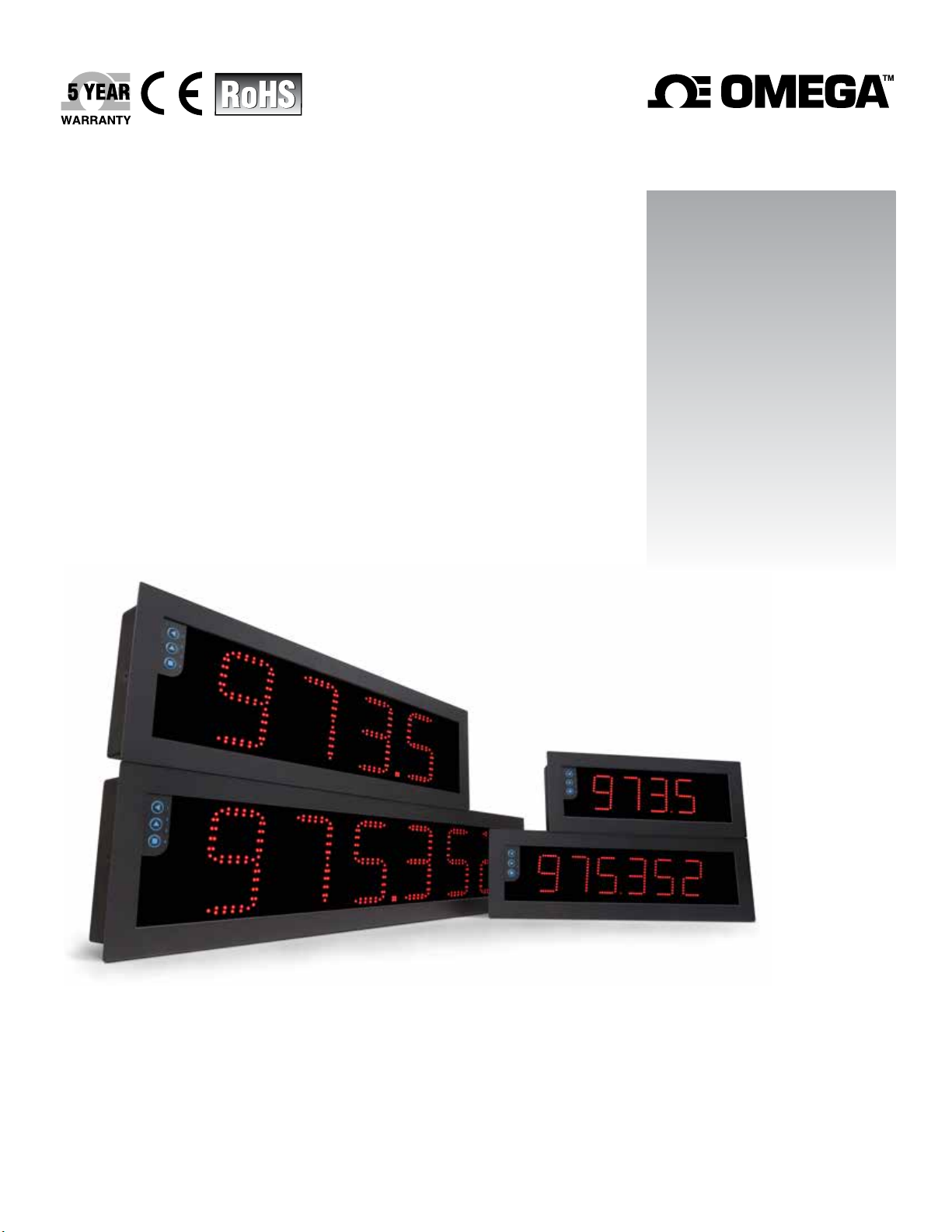
Large format industrial meters for process signals
Large format meters for long distance reading, for industrial
applicaons. Dierent formats available with 4 and 6 digits,
with 60 mm and 100 m digit height. Front keypad to access the
conguraon menu, and oponal remote keypad.
Models to measure process signals in mA and Vdc. Provides
excitaon voltage congurable from +5 Vdc to +20 Vdc (max.
35 mA) to power up transducers. Scalable reading with
selectable decimal point posion.
Output and control opons with 1, 2 and 3 relays, transis
tor outputs, controls for SSR relays, isolated analog outputs,
communicaons in Modbus RTU, RS485 ASCII and RS232.
Sturdy metal housing with full IP65 protecon. Internal
connecons by plug-in screw clamp terminals, and output
through cable glands. Housing prepared for panel, wall and
hanging mount.
• Congurable ‘Fast access’ to selected funcons with key
‘UP’ (5) (see secon 1.12.11)
• ‘On power up’ for system protecon on ‘cold’ start-up
and / or acvaon of automac tare (see secon 1.12.12)
• up to 20 segments for signal linearizaon (see secon
1.12.8)
• ‘Field correcon’ for fast and easy ‘on the eld’ correcon
of osets and signal dris (see secon 1.12.3)
-
• alarms with 1 or 2 setpoints, independent acvaon and
deacvaon delays, hysteresis, manual unlocking, ... (see
secon 1.12.4)
• ‘Tare’ funcon for weight applicaons (see secon 1.12.14)
• ‘Peak & Hold’ for test break applicaons (see secon 1.12.9)
Mulple display lters, memory of maximum and minimum
reading, password protecon, 5 brightness levels.
1.1 How to use this manual
If this is the rst me you are conguring a large format
meter, below are the steps to follow to install and congure
the instrument.
1. Idenfy the instrument format (see secon 1.4)
2. Power and signal connecons
- open the instrument (see secon 1.5)
- connect the power (see secon 1.7)
- connect the signal and select jumper mA/Vdc
(see secon 1.8)
- close the instrument (see secon 1.5)
3. Congure the instrument (see secon 1.12)
- select the signal range, the decimal point posion and
scale the reading (see secon 1.12.2)
4. Advanced conguraon (oponal)
- congure the instrument alarms (see secon 1.12.4)
- congure the display lters (see secon 1.12.7)
Read all the manual secons in order to have a full and clear
view of the characteriscs of the instrument. Do not forget
to read the installaon precauons at secon 1.17.
5. If the instrument includes analog output (AO) or serial
communicaons (RTU, S4, S2)
- to include an opon to an instrument see secon 1.6
- to congure an installed opon, access the opon
conguraon menu (see secon 1.12.20)
- see secon 2 for informaon regarding the output and
control opons available
6. Install the instrument
- mount on panel, wall or hanging (see secon 1.16)
- adjust the brightness level according to your
environmental needs (see secon 1.12.19)
- congure the fast access (see secon 1.12.11)
- congure the excitaon voltage (see secon 1.12.15)
- congure other funcons : segment linearizaon
(1.12.8), ‘on power up’ (1.12.12), key ‘LE’ (1.12.13), tare
(1.12.14), password (1.12.16)
2
Page 4

1.2 How to order
Format
LDB-24 P
LDB-24 (60 mm, 4 digits)
LDB-26 (60 mm, 6 digits)
LDB-44
LDB-46
Model Power
-
(100 mm, 4 digits)
(100 mm, 6 digits)
H -
-H (85-265 Vac
and 120-370 Vdc)
-L
(11-36 Vdc isolated)
Color
-
-R (red led)
-G
(green led)
1.3 Index
1. LDB-P
Series . . . . . . . . . . . . . . . . . . . . . . . . . 2
1.1 How to use this manual . . . . . . . . . . . . . . . . 2
1.2 How to order . . . . . . . . . . . . . . . . . . . . . . 3
1.3 Index . . . . . . . . . . . . . . . . . . . . . . . . . . . 3
1.4 Sizes and formats . . . . . . . . . . . . . . . . . . . . 4
1.4.1 Format LDB-24. . . . . . . . . . . . . . . . . . . . 4
1.4.2 Format LDB-44. . . . . . . . . . . . . . . . . . . . 4
1.4.3 Format LDB-26. . . . . . . . . . . . . . . . . . . . 5
1.4.4 Format LDB-46. . . . . . . . . . . . . . . . . . . . 5
1.5 To access the instrument. . . . . . . . . . . . . . . . 6
1.6 Modular system. . . . . . . . . . . . . . . . . . . . . 6
1.7 Power connecons and protecve earth . . . . . . .7
1.8 Input signal connecons . . . . . . . . . . . . . . . . 7
1.8.1 Connecon examples . . . . . . . . . . . . . . . . 8
1.9 Connecons for remote keypad . . . . . . . . . . . . 8
1.10 Funcons included . . . . . . . . . . . . . . . . . . 8
1.11 Technical specicaons . . . . . . . . . . . . . . . . 9
1.12 Conguraon . . . . . . . . . . . . . . . . . . . . 10
1.12.1 How to operate the menus . . . . . . . . . . . 10
1.12.2 Inial set-up . . . . . . . . . . . . . . . . . . . 11
1.12.3 Field correcon . . . . . . . . . . . . . . . . . 12
1.12.4 Alarms . . . . . . . . . . . . . . . . . . . . . . 12
1.12.5 Field correcon menu . . . . . . . . . . . . . . 13
1.12.6 Alarms conguraon menu . . . . . . . . . . . 13
1.12.7 Display lters . . . . . . . . . . . . . . . . . . . 14
1.12.8 Segment linearizaon . . . . . . . . . . . . . . 14
1.12.9 Display lters conguraon menu . . . . . . . 15
1.12.10 Tools conguraon menu . . . . . . . . . . . 15
1.12.11 Fast access . . . . . . . . . . . . . . . . . . . 16
1.12.12 ‘on power up’ funcon. . . . . . . . . . . . . 16
1.12.13 ‘LE’ key . . . . . . . . . . . . . . . . . . . . . 16
Opon 1
- -
-R1 (1 relay)
-AO (analog output)
-RTU (Modbus RTU)
-S4 (RS-485)
-S2 (RS-232)
-T1 (1 transistor)
-SSR (1 control SSR)
-0 (empty)
Opon 2
Opon 3*
-
*Opon 3 available
with formats LDB-26
and LDB-46
Others
-
1.12.14 ‘Tare’ funcon . . . . . . . . . . . . . . . . . 16
1.12.15 Excitaon voltage. . . . . . . . . . . . . . . . 16
1.12.16 Password conguraon . . . . . . . . . . . . 18
1.12.17 Default factory conguraon . . . . . . . . . 18
1.12.18 Firmware version . . . . . . . . . . . . . . . . 18
1.12.19 Brightness conguraon . . . . . . . . . . . . 18
1.12.20 Access to the opons conguraon menu . . 18
1.13 Factory conguraon . . . . . . . . . . . . . . . . 19
1.14 Messages and errors . . . . . . . . . . . . . . . . 19
1.15 Full conguraon menu. . . . . . . . . . . . . . . 20
1.16 Mounng. . . . . . . . . . . . . . . . . . . . . . . 22
1.17 Installaon precauons . . . . . . . . . . . . . . . 23
1.18 Warranty . . . . . . . . . . . . . . . . . . . . . . . 23
1.19 CE declaraon of conformity . . . . . . . . . . . . 23
2. Output and control modules . . . . . . . . . . . . . . 24
2.1 Module R1 . . . . . . . . . . . . . . . . . . . . . . . 24
2.2 Module T1 . . . . . . . . . . . . . . . . . . . . . . . 24
2.3 Module SSR . . . . . . . . . . . . . . . . . . . . . . 25
2.4 Module AO . . . . . . . . . . . . . . . . . . . . . . 25
2.5 Module RTU . . . . . . . . . . . . . . . . . . . . . . 26
2.6 Module S4 . . . . . . . . . . . . . . . . . . . . . . . 26
2.7 Module S2 . . . . . . . . . . . . . . . . . . . . . . . 27
3
Page 5
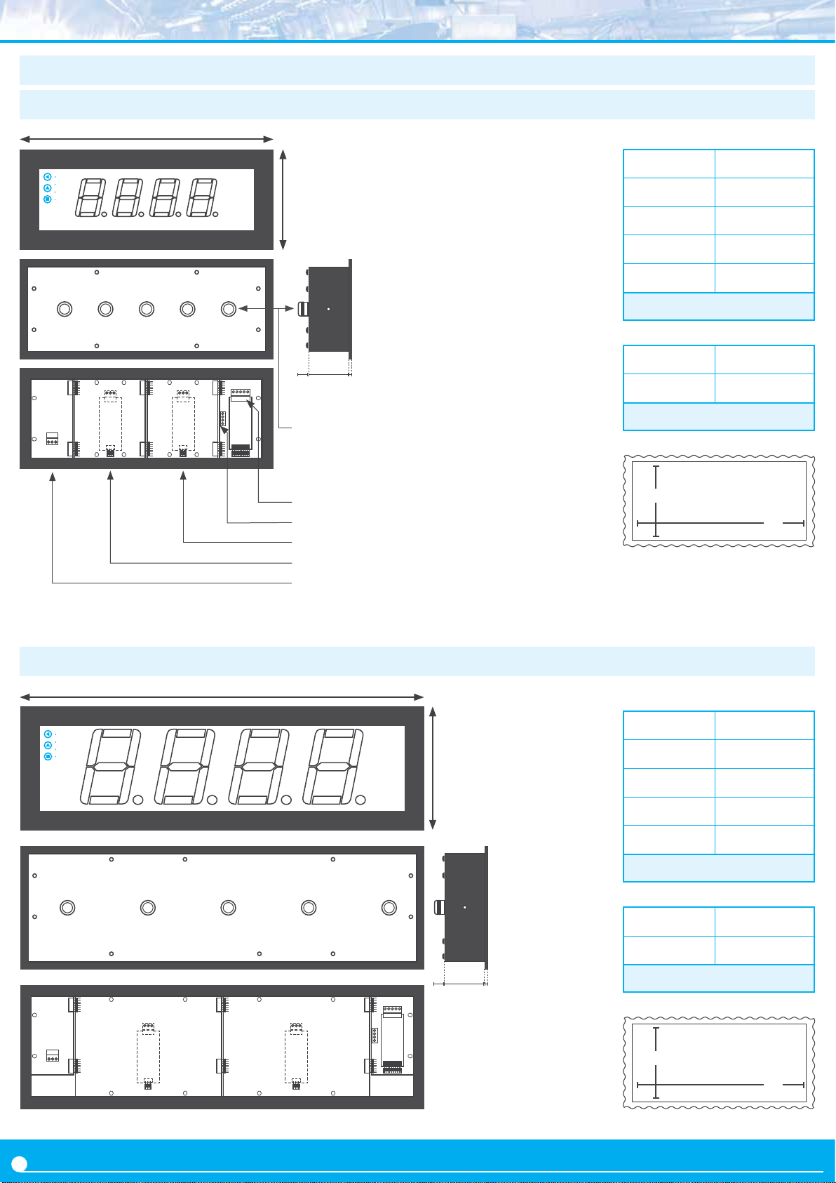
1.4 Sizes and formats
1.4.1 Format LDB-24
A
Size A 340 mm
Power
Opon 2 Opon 1
Remote keypad
Signal
B
CDE
Cable glands
Input signal terminal
Remote keypad terminal
Slot for opon 1
Slot for opon 2
Power
Size B 135 mm
Size C 3 mm
Size D 55 mm
Size E 25 mm
Table 1 - Sizes LDB-24
Cut-out G 322 mm (±1)
Cut-out F 117 mm (±1)
Table 2 - Panel cut-out LDB-24
Panel cut-out
(see Table 2)
F
G
1.4.2 Format LDB-44
Power
Opon 2 Opon 1
A
Size A 542 mm
B
Size B 166 mm
Size C 3 mm
Size D 55 mm
Size E 25 mm
Table 3 - Sizes LDB-44
Remote keypad
Signal
Cut-out G 524 mm (±1)
Cut-out F 148 mm (±1)
Table 4 - Panel cut-out LDB-44
CDE
Panel cut-out
(see Table 4)
F
G
4
Page 6
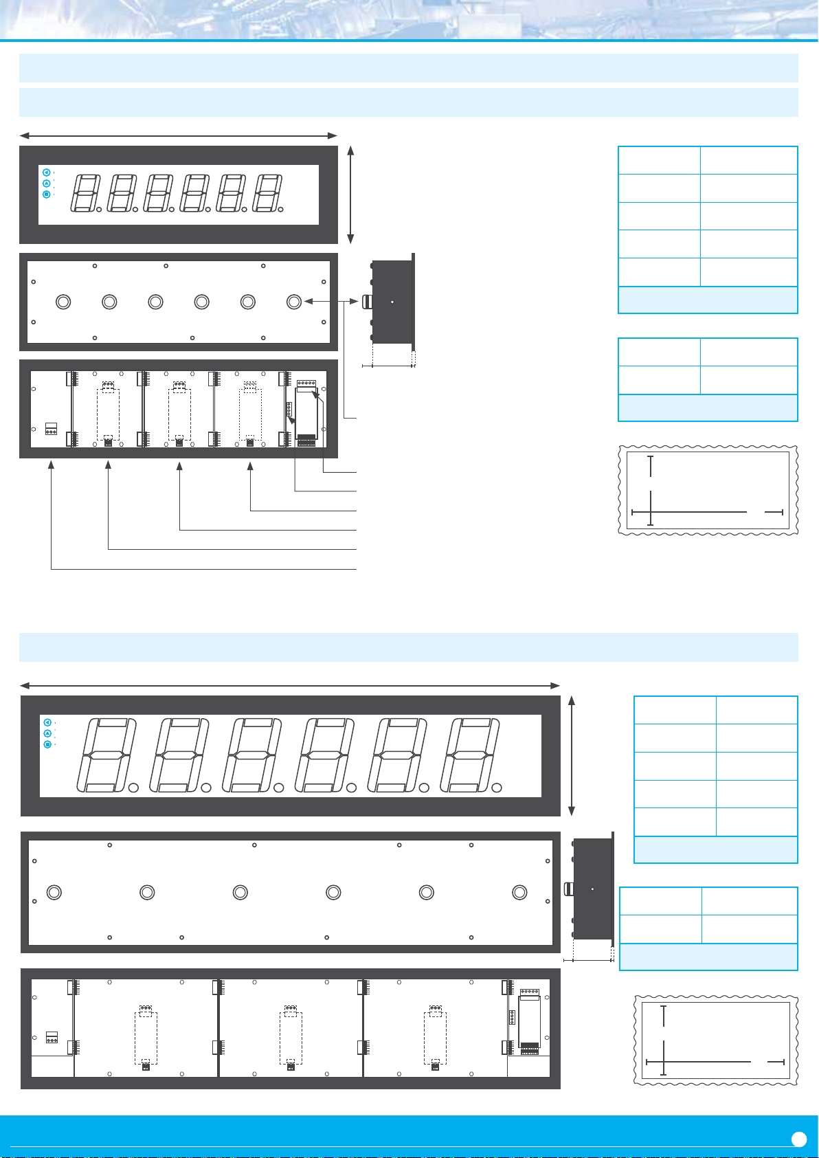
1.4.3 Format LDB-26
A
Size A 436 mm
Power
Opon 3 Opon 2
Remote keypad
B
Size B 135 mm
Size C 3 mm
Size D 55 mm
Size E 25 mm
Table 5 - Sizes LDB-26
SignalOpon 1
Cut-out G 418 mm (±1)
CDE
Cable glands
Input signal terminal
Remote keypad terminal
Slot for opon 1
Slot for opon 2
Slot for opon 3
Power
Cut-out F 117 mm (±1)
Table 6 - Panel cut-out LDB-26
Panel cut-out
(see Table 6)
F
G
1.4.4 Format LDB-46
Power
Opon 3 Opon 2
A
Size A 740 mm
B
Size B 166 mm
Size C 3 mm
Size D 55 mm
Size E 25 mm
Remote keypad
Table 7 - Sizes
SignalOpon 1
Cut-out G 722 mm (±1)
LDB-46
Cut-out F 148 mm (±1)
Table 8 - Panel cut-out LDB-46
CDE
Panel cut-out
(see Table 8)
F
G
5
Page 7
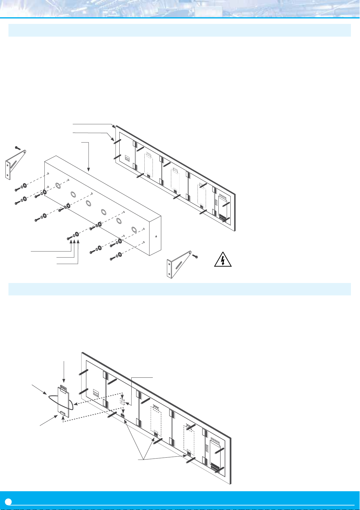
1.5 To access the instrument
To open the housing, remove the screws from the back
cover. With each screw there is a metal washer and a plasc
washer. Once the screws are out, remove the back cover.
The gure below shows the instrument internal structure for
a LDB-26 format. It shows the locaon of the 3 slots for opon
al output and control modules, the power terminal and the
input signal terminal.
Waterght seal
Female turret
Power
Slot for opon 3Back cover
To close the instrument, place the back cover, the screws,
the metal washer and the plasc washer. The plasc washer
is in contact with the back cover. Conrm that the screws are
correctly turning inside the internal female screws.
-
To ensure a correct IP65 protecon ghten the back cover
screws with a strength between 30 and 40 Ncm, with the
help of a dynamometer screwdriver.
Slot for opon 2
Slot for opon 1
Remote keypad terminal
Input signal terminal
Screw
Metal washer
Plasc washer
1.6 Modular system
Large format meters are designed with an
internal modular architecture. The output and control
modules are independent and can be installed by accessing
the internal circuits of the instrument, and connecng the
module to the connecon jumpers of the selected slot.
Output and control module
Slot 3
Tie base
Cable e
Slot 2
(2)
(1)
Module pins
Risk of electric shock. Removing the back
cover will grant access to the internal
circuits of the instrument. Operaon must
be performed by qualied personnel only.
Each module is provided with a cable e to x the
module to the e base. The input signal modules denes the
instrument funcon and are exchangeable, switching a
temperature meter to an impulse counter only by replacing
the input signal module.
See secon 2. for informaon regarding the output and
control opons available
To install an output and control module
(1) insert the ‘module pins’ into the
Slot 1
‘connecon jumpers’ in one of the
free slots
(2) place the ‘cable e’ into the ‘e
base’ and embrace the ‘module’
rmly, unl it is xed
Connecon jumpers
6
Page 8
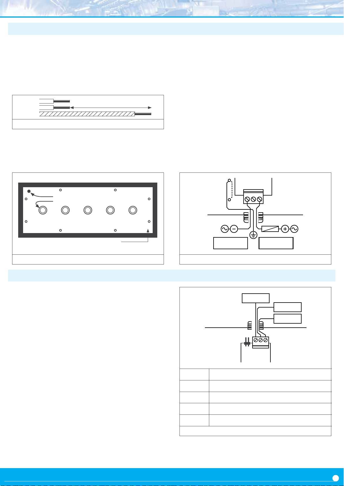
1.7 Power connecons and protecve earth
1. Unscrew the screws from the back cover and remove the
back cover (see secon 1.5).
2. Pass the power cable through the power cable gland
(see secon 1.4).
3. Prepare the power cables so that the earth wire is 20 cm
longer than the other cables (see Figure 1).
Phase (+)
Neutral (-)
Earth
Figure 1 - Longer earth wire
20 cm
4. Connect the earth wire to the internal xed screw ‘PE’
(see Figure 2) located at the inside of the back cover. The
instrument internally connects the back cover metallic
‘PE’ internal xed screw
Power cable gland
structure with the front metallic structure through an
internal green-yellow cable. (doed cable at Figure 3).
5. Connect phase and neutral (in AC power) or posive and
negave (in DC power) to the internal power terminal.
6. The connecons label aached to the outside of the
instrument has some free space le to write the color or
local code for each cable.
7. To comply with security regulaon 61010-1, add to the
power line a protecon fuse acng as a disconnecon
element, easily accessible to the operator and idened
as a protecon device.
Power ‘H’ 500 mA me-lag fuse
Power ‘L’ 1000 mA me-lag fuse
Power Terminal
PE
(orange)
N
L
Screws
Figure 2 - Locaon of the internal ‘PE’ xed screw and power cable gland
1.8 Input signal connecons
1. Unscrew the screws from the back cover and remove the
back cover (see secon 1.5).
2. Locate the input signal terminal (see secon 1.4). For
signal connecon examples see secon 1.8.1
3. Pass the signal cable through the signal cable gland
(see secon 1.4).
4. Connect the input signal cables (see Figure 4) and select
the appropriate jumper ‘mA’ or ‘Vdc’.
5. The connecons label aached to the outside of the
instrument has some free space le to write the color or
local code for each cable.
fuse
PE
Figure 3 - Power connecons
V exc.
mA / Vdc
Common
Input Signal
mA
Vdc
2
3
1
mA
/
Vdc Input signal in mA or Vdc
Vexc Excitaon voltage to power the transducer
Common
Jumper mA
Jumper Vdc
Figure 4 - Signal connecons
Close for mA signals (and open Vdc)
Close for Vdc signals (and open mA)
7
Page 9
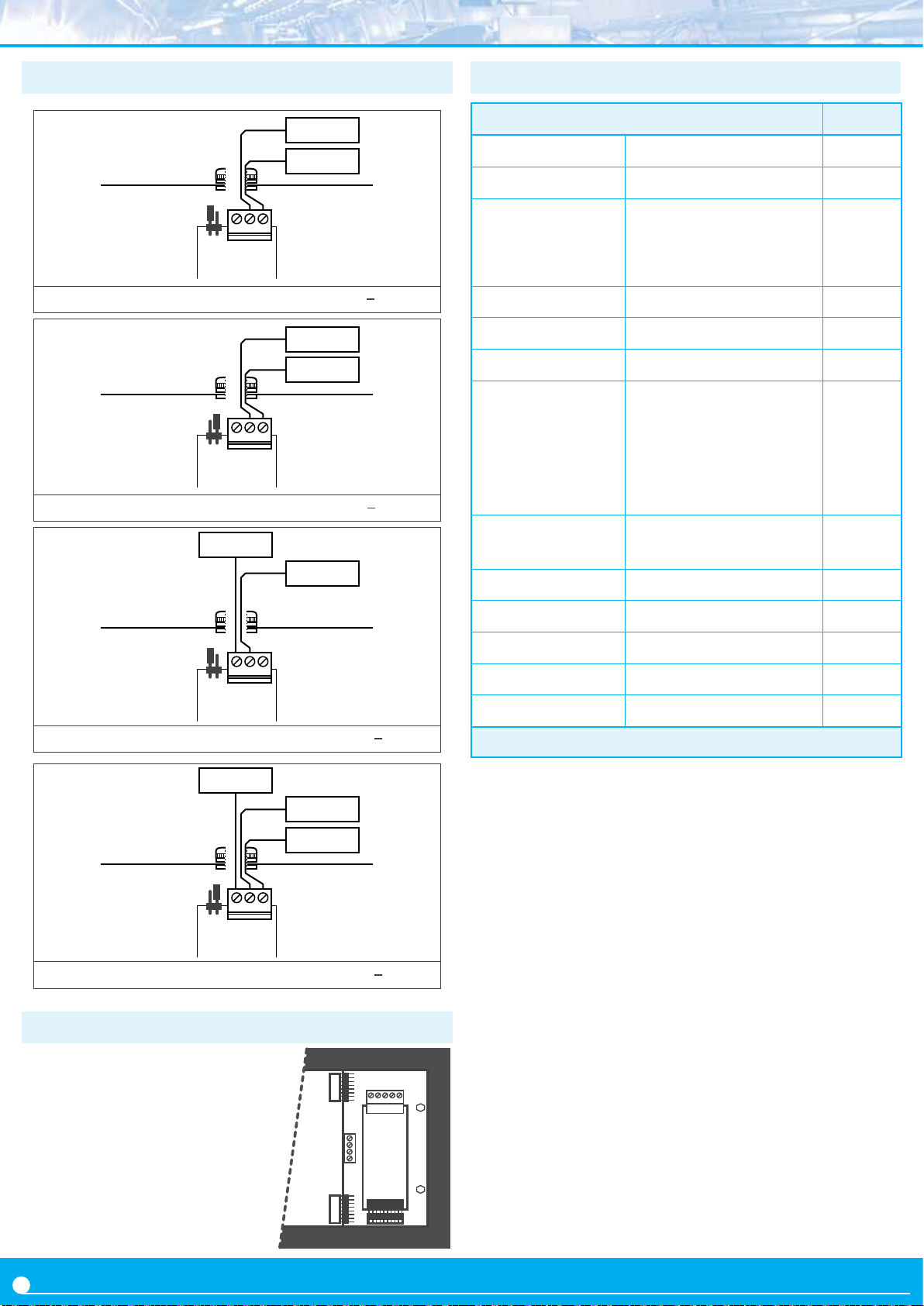
1.8.1 Connecon examples
1.10 Funcons included
signal mA
common
Input Signal
mA
Vdc
2
3
1
Figure 5 - Connecons for acve 4/20 mA signals (or ±20 mA)
+ Vdc
0 Vdc
Input Signal
mA
Vdc
2
3
1
Figure 6 - Connecons for acve 0/10 Vdc signals (or ±10 Vdc)
V exc.
signal mA
Funcons included Secon
Fast access menu yes, congurable 1.12.11
Segment linearizaon up to 20 segments 1.12.8
Display lters recursive
‘steps’
xed digits
1.12.7
le zeros
‘On Power Up’ yes
1.12.12
Excitaon voltage congurable 1.12.15
‘Measure’ yes 1.12.11
simple or double setpoint
acvaon delays
Alarms
deacvaon delays
hysteresis
1.12.4
inverted relays
locked alarms
Field correcon yes, for high and low
signals
1.12.3
‘Peak & Hold’ yes 1.12.7
Input Signal
mA
Vdc
2
3
1
Figure 7 - Connecons for passive 4/20 mA signals (or ±20 mA)
V exc.
+ Vdc
0 Vdc
Input Signal
mA
Figure 8 - Connecons for passive
2
3
1
Vdc
0/10 Vdc signals (or ±10 Vdc)
1.9 Connecons for remote keypad
The 4 pin terminal located beside
the input signal module allows to
replicate a remote version of the
front keypad. Connect 4 cables for
front keys ‘SQ’ (<), ‘UP’ (5) and
‘LE’ (3) and for the common. Pass
these cables through the ‘remote
keypad’ cable gland (see secon
1.4).
GND
SQ
UP
LE
Tare funcon yes 1.12.14
Memory maximum, minimum 1.12.11
Password conguraon locked 1.12.16
Brightness
Table 9 - Funcons included
congurable, 5 levels 1.12.19
8
Page 10

1.11 Technical specicaons
Digits
number of digits 4 or 6 (see Table 10)
digit 7 segments
view angle 120º
color red or green
digit height (see Table 10)
Reading
max., min. (see Table 10)
decimal point congurable
overrange / underrange ash reading
acquisions (see Table 10)
display refresh (see Table 10)
step response (see Table 10)
Input signal
signal ranges 4/20 mA, ±
20 mA
0/10 Vdc, ±10 Vdc
maximum oversignal 100 mA or 100 Vdc
input impedance 11 R en mA, 932 K en Vdc
accuracy 0.05 % o 0.03 % (see Table 10)
thermal dri oset 10 ppm / ºC
thermal dri span* 25 ppm / ºC
(*included oset thermal dri)
wire secon max. 0.5 mm
2
Excitaon voltage
voltage output +20 Vdc, +15 Vdc, +10 Vdc, +5 Vdc
selectable by menu
accuracy ±5 %
maximum current 35 mA
protecon against short circuit
Power
power ‘H’ 85 to 265 Vac and 120 to 370 Vdc
isolated (isolaon 2500 Vac)
power ‘L’ 11 to 36 Vdc isolated
(isolaon 1500 Vdc)
consumpon (see Table 10)
fuses (see secon 1.7)
wire secon max. 2.5 mm
2
Conguraon front keypad with 3 keys
remote keypad (see secon 3.1)
Output and control opons relay output, analog retransmission,
Modbus RTU, ... (see secon 2)
Mechanical
IP protecon full IP65 housing
mounng panel, wall , hanging (see secon
1.16)
connecons cable gland outputs
internal plug-in screw terminals
housing material
textured iron, black painted
methacrylate front lter
weight (see Table 10)
front sizes (see secon 1.4)
panel cut-out (see secon 1.4)
depth (see secon 1.4)
Temperature
operaon from 0 to +50 ºC
storage from -20 to +70 ºC
warm-up me 15 minutes
Format LDB-24 Format LDB-44 Format LDB-26 Format LDB-46
Number of digits 4 4 6 6
Digit height 60 mm 100 mm 60 mm 100 mm
Reading distance 25 meters 50 meters 25 meters 50 meters
Accuracy (% F.S.) 0.05 % 0.05 % 0.03 % 0.03 %
Acquisions / second 15 15 3.5 3.5
Refresh / second 15 15 3.5 3.5
Step response (0 % to 99 % of signal) 120 mSec. 120 mSec. 300 mSec. 300 mSec.
Slots for output and control opons 2 2 3 3
Maximum / minimum reading 9999 / -1999 999999 / -199999
Consumpon (without opons installed) 3 W 5.25 W 3.5 W 5.5 W
Consumpon (with opons installed) 5 W 6.75 W 5.5 W 7 W
Weight 2200 gr. 2500 gr. 3500 gr. 4500 gr.
Table 10 - Technical specicaons associated to format
9
Page 11
1.12 Conguraon
1.12.1 How to operate the menus
The instrument has two menus accessible to the user :
‘Conguraon menu’ (key ‘SQ’) (<)
‘Fast access’ menu (key ‘UP’) (5)
Conguraon menu
The ‘conguraon menu’ modies the conguraon
parameters to adapt the instrument to the applicaon needs.
To access the ‘conguraon menu’ press for 1 second
the ‘SQ’ (<) key. This access can be blocked by acvating the ‘Password’ (‘PASS’) funcon. While operang the
‘conguraon menu’, the alarm status is ‘hold’ to the
status it had before accessing the menu, and the output and
control modules remain in ‘error’ state. When leaving the
‘conguraon menu’, the instrument applies a system reset, followed by a brief disconnecon of the alarms and the
output and control modules. Funconality is then recovered.
For a detailed explanaon on the ‘conguraon menu’
see the following secons, and for a full view of the
‘conguraon menu’ see secon 1.15.
Key ‘LE’ (3) - press the ‘LE’ (3) key to acvate the cong-
ured special funcons associated to this key. Inside the menu,
the ‘LE’ (5) acts as an ‘ESCAPE’. It leaves the selected menu
level and eventually, by leaving all menu levels, it leaves
from the conguraon menu. Then changes are applied and
the instrument is back to normal funcon. When entering a
numerical value, it selects the acve digit, and the value is
then modied by key ‘UP’ (5).
‘Rollback’
Aer 30 seconds without interacon from the operator, the
instrument will rollback and leave the ‘conguraon menu’
or the ‘fast access’ menu. All changes will be discarded.
Instruments with 4 and 6 digits
The conguraon menus included in this document show
values for a 6 digit instrument. In case of 4 digit instruments,
note that maximum reading values should be 9999 instead
of 999999 to 9999 and minimum reading values should be
-1999 instead of -199999.
‘Fast access’ menu
The ‘fast access’ menu is an operator congurable menu,
providing fast and direct access to the most usual funcons
of the instrument with a single key pad stroke. Press key ‘UP’
(5) to access this menu.
See secon 1.12.11 for a list of selectable funcons for the
‘fast access’ menu in this instrument. The ‘Password’ (‘PASS’)
funcon does not block access to this menu. Accessing and
modifying parameters in the ‘fast access’ menu does not
interfere with the normal funconality of the instrument,
and it does not generate any system reset when validang
the changes.
Operang with the front keypad inside the menus
Key ‘SQ’ (<) - press the ‘SQ’ (<) key for 1 second to ac
-
cess the ‘conguraon menu’. Inside the menu, the ‘SQ’ (<)
key acts as an ‘ENTER’. It enters into the menu opon se
-
lected, and when entering a numerical value, it validates the
number.
Key ‘UP’ (5) - press the ‘UP’ (5) key to access the ‘fast
access’ menu. Inside the menu,the ‘UP’ (5) key sequen-
ally moves through the available parameters and menu entries. When entering a numerical value, it modies the digit
selected by increasing its value to 0, 1, 2, 3, 4, 5, 6, 7, 8, 9.
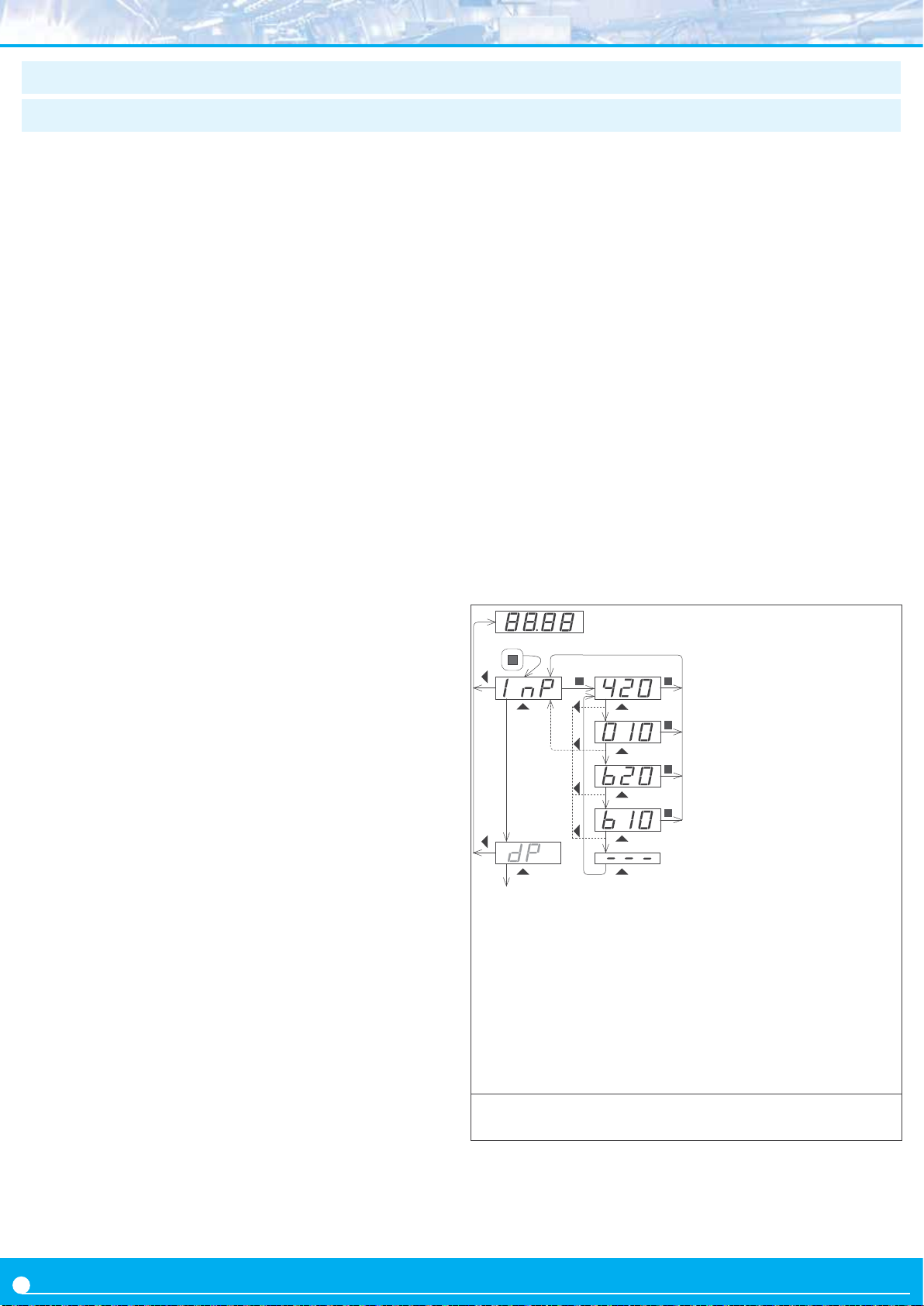
Example of operaon inside
(1)
(6)
(6)
(3)
(2)
(5)
(3)
(5)
(3)
(5)
(3)
(5)
(3)
the ‘conguraon menu’.
(4)
1. The (<) key enters into the
‘conguraon menu’.
(4)
2. The (<) key enters into the
(4)
‘InP’ menu.
3. The (5) key moves through
(4)
the menu opons.
4. The (<) key selects the
desired range and returns
(3)
(3)
to the ‘InP’ menu.
5. The (3) key leaves the
actual menu level and
moves to the previous
menu level.
6. The (3) key leaves the
‘conguraon menu’.
Changes are applied and
Figure 9 - Example of operaon inside the ‘conguraon menu’
saved at this moment.
10
Page 12
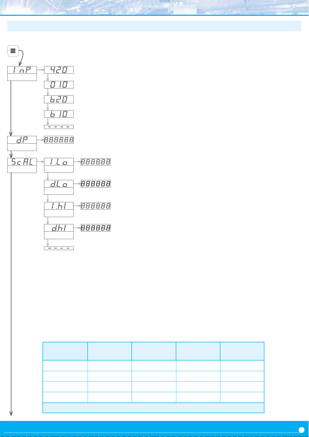
1.12.2 Inial set-up
Press ‘SQ’ (<) for 1 second to access the ‘conguraon
menu’. For a descripon on how to operate inside the menus
see secon 1.12.1. For a full vision of the ‘conguraon menu’
structure see secon 1.15.
Input
Decimal point
Scaling
Input Low
Display Low
4/20 mA input signal range
0/10 Vdc input signal range
±20 mA input signal range
±10 Vdc input signal range
To congure the inial set up of the instrument, select the
input signal range, the decimal point posion, and scale the
reading.
At the ‘Input’ (‘Inp’) parameter, select the input signal range.
• select ‘420’ for 4/20 mA signals. Close the ‘mA’ jumper
(see secon 1.8). It accepts acve and passive signals. See
connecons at secon 1.8.1.
• select ‘010’ for 0/10 Vdc signals. Close the ‘Vdc’ jumper
(see secon 1.8). It accepts acve and passive signals. See
connecons at secon 1.8.1.
• select ‘b20’ for ±20 mA signals. Close the ‘mA’ jumper
(see secon 1.8). It accepts acve and passive signals. See
connecons at secon 1.8.1.
• select ‘b10’ for ±10 Vdc signals. Close the ‘Vdc’ jumper
(see secon 1.8). It accepts acve and passive signals. See
connecons at secon 1.8.1.
At the ‘Decimal point’ (‘dP’) parameter, select the decimal
point posion. Move the decimal point with the ‘LE’ (3) key.
At the ‘Scaling’ (‘ScAL’) menu, congure the reading fot the
input signal range selected. The parameters are:
Input High
Display High
Range
Input Low
(‘I.Lo’)
• at the ‘Input Low’ (‘I.Lo’) parameter congure the low
input signal, in mA or Vdc, with two decimals.
• at the ‘Display Low’ (‘d.Lo’) parameter congure the
reading associated to the low input signal congured
before.
• at the ‘Input High’ (‘I.hI’) parameter congure the high
input signal, in mA or Vdc, with two decimals.
• at the ‘Display High’ (‘d.hI’) parameter congure the
reading associated to the high input signal congured
before.
Display Low
(‘d.Lo’)
Input High
(‘I.hI’)
Display High
(‘d.hI’)
4/20 mA 4.00 mA 0 20.00 mA 1000
0/10 Vdc 0.00 Vdc 0 10.00 Vdc 1000
±20 mA -20.00 mA -1000 20.00 mA 1000
±10 Vdc -10.00 Vdc -1000 10.00 Vdc 1000
Table 11 - Scaling parameter default values for each signal range
11
Page 13
1.12.3 Field correcon
The ‘Field correcon’ (‘F.cor’) funcon corrects the
instrument reading once installed on the eld. Reading
osets and deviaons can occur due to inaccuracies on the real
signal. The ‘eld correcon’ funcon oers a fast and easy way
to compensate for this inaccuracies.
Generate the low input signal and if the reading is not as
desired, acvate the ‘low level’ eld correcon funcon. The
instrument will congure itself so that with the actual input
signal, the reading is as indicated at the ‘d.Lo’ parameter. Field
correcon can be applied to the low input signal and to the
1.12.4 Alarms
The instrument manages 3 independent internal alarms,
each one controlling the acvaon of an oponal relay,
transistor or control SSR output.
Oponal modules (see secon 2) are installed at the free
slots inside the instrument (see secon 1.4). LDB-24 and
LDB-44 formats have 2 free slots for output and control
modules, while LDB-26 and LDB-46 formats have 3 free
slots for output and control modules.
The instrument has 3 front leds that reect the state of the
3 internal alarms. These leds are only for local help during
installaon, as they are not appropriate for long distance
reading.
Each alarm controls the acvaon of the relay, transistor
or control SSR installed on its associated slot, and the front
led.
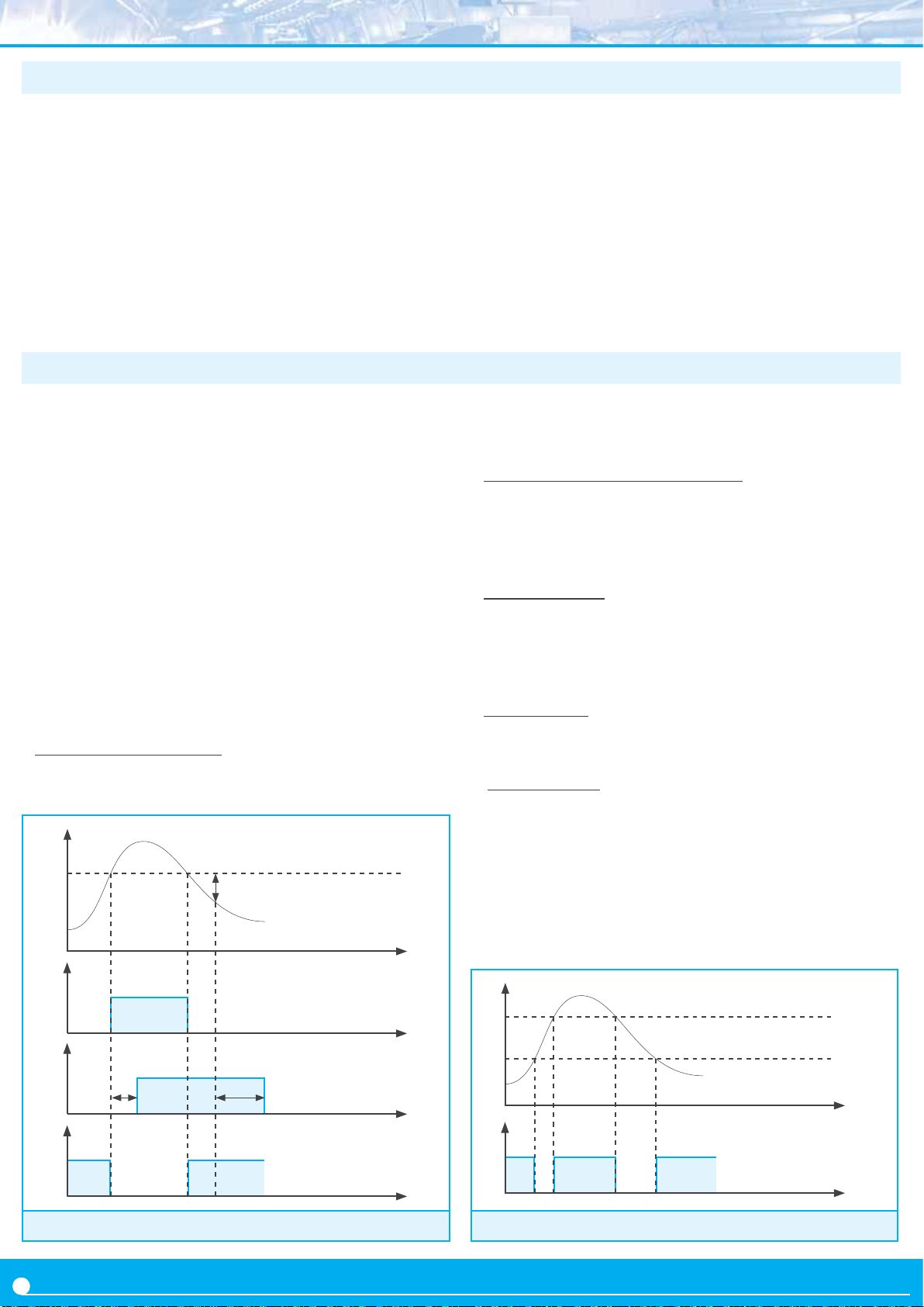
• Congurable parameters
Each alarm has several parameters for conguraon,
starng with the usual setpoint, hysteresis and maximum
Reading
setpoint
hysteresis
t
on
o
Alarm as maximum, no
hysteresis, no delays
t
high input signal.
Example:
a 0/10 Bar pressure transmier provides a
4/20 mA output signal. At installaon, the operator
detects that the reading at 0 Bar is 0.34 Bar and that at
10 Bar the reading is 10.72 Bar.
Apply the ‘Field correcon’ / ‘F.Lo’ funcon while reading is 0.34 Bar and the instrument will automacally correct the reading to 0.00 Bar. Aerwards, apply the ‘Field
correcon’ / ‘F.Hi’ funcon while reading is 10.72 Bar and
the instrument will automacally correct the reading to
10.00 Bar.
(alarm acve when reading is higher than setpoint) or
minimum (alarm acve when reading is lower than
minimum) alarm types (see Figure 10).
• Acvaon and deacvaon delays
Each alarm can congure independent acvaon and
deacvaon delays. These delays aect the alarm as a
whole, and the delay will aect the front led and the
associated relay.
• Second setpoint
Conguring a second setpoint creates ‘windowed alarms’.
The windowed alarm controls with a single relay output
if the reading is inside or outside the values dened (see
Figure 11).
• Inverted relay
Acvate the ‘inverted relay’ funcon to invert the
acvaon logic of the associated relay.
• ‘Locked alarms’
Acvate the ‘locked alarms’ funcon will force the operator
to interact with the instrument when an alarm has been
acvated. Once acvated, the alarm will remain locked at
acve state, even if the reading returns to a value below
setpoint, unl the operator manually unlocks the alarms
pressing the front key ‘LE’ (or the remote key ‘LE’, see
secon 3.1).
Reading
Setpoint 2
Setpoint 1
on
o
acvaon
delay
on
o
Figure 10 - Examples of alarm with 1 setpoint
12
deacvaon
delay
Alarm as maximum,
hysteresis and delays
Alarm as minimum, no
hysteresis, no delays
t
Alarm as minimum
on
o
t
Figure 11 - Example of alarm with 2 setpoints
double setpoint, no hysteresis, no delays
t
, with
t
Page 14
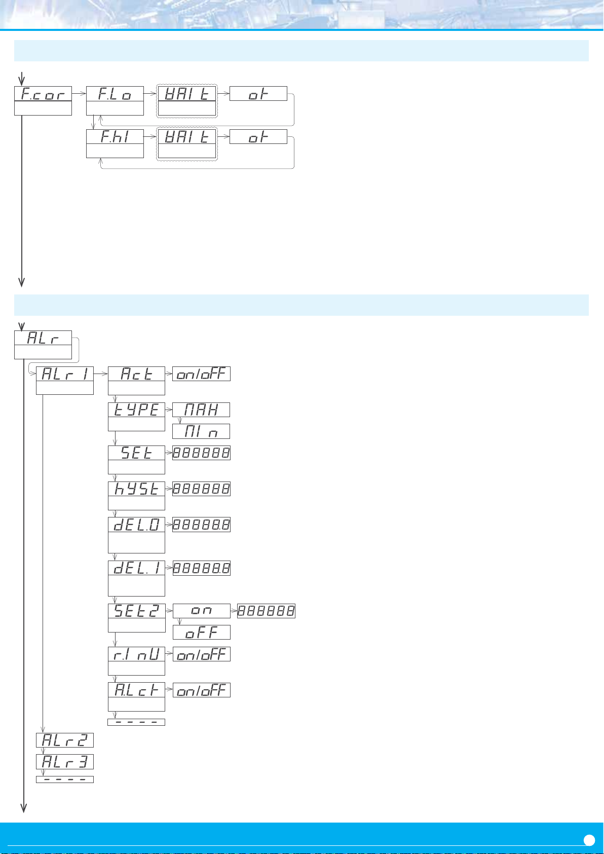
1.12.5 Field correcon menu
Field correcon
Correcon Low
Correcon High
Wait (5 sec.)
Wait (5 sec.)
To operate the ‘Field Correcon’ (‘F.cor’) funcon for the
oset, generate the low input signal and access the ‘Field Low’
(‘F.Lo’) funcon. The instrument starts the correcon process:
(<)
• message with the measurement type (‘mA’ or ‘Vdc’)
• message ‘wait’ (‘WAIt’) in ash mode
(<)
• aer 5 seconds, message ‘ok’ (‘oK’)
• at this point, press key ‘SQ’ (<)
• the menu returns to menu entry ‘Field Low’ (‘F.Lo’)
1.12.6 Alarms conguraon menu
Alarms
Alarm 1
Acve
Type of alarm
Setpoint
Hysteresis
Acvaon
delay
Deacvaon
delay
Setpoint 2
Inverted relay
Locked alarm
The instrument has read the input signal value and automa
cally applies the value to the ‘Input Low’ (‘I.Lo’) parameter.
For the high signal, repeat the process generang the high
input signal and access the ‘Field High’ (‘F.hI’) funcon. The
instrument reads the input signal value and automacally
applies the value to the ‘Input high’ (‘I.hI’) parameter.
To congure the alarm, access the alarm menu (‘ALr1’, ‘ALr2’
or ‘ALr3’) and congure the following parameters :
• at the ‘Acve’ (‘Act’) parameter select ‘on’
• at the ‘Type of alarm’ (‘TypE’) parameter select ‘MAX’ for
maximum alarm (acvates when reading is higher than
setpoint), or ‘MIn’ for minimum alarm (acvates when
reading is lower than setpoint).
• at the ‘Setpoint’ (‘SEt’) parameter congure the alarm ac
vaon point. Parameter value is accessible through ‘fast
access’ (see secon 1.12.11).
• at the ‘Hysteresis’ (‘hySt’) parameter select the hysteresis
value. Hysteresis applies to the alarm deacvaon. Alarm
deacvates once the reading is beyond the setpoint plus
the hysteresis value. Hysteresis prevents relay switching in
case of signal uctuaons close to the setpoint value.
• at the ‘Acvaon delay’ (‘dEL.0’) parameter congure the
delay to apply before the alarm is acvated. Delay starts to
count once the setpoint is reached. Value from 0.0 to 99.9
seconds.
• at the ‘Deacvaon delay’ (‘dEL.1’) parameter cong
ure the delay to apply before the alarm is deacvated.
Delay starts to count once the setpoint is reached plus the
hysteresis value. Value from 0.0 to 99.9 seconds.
• to work with ‘windowed alarms’ (see Figure 11) acvate
‘Setpoint 2’ (‘SEt2’) to ‘on’ and then congure the desired
second setpoint value. Second setpoint must always be
higher in value than the rst setpoint.
• at the ‘Inverted relay’ (‘r.Inv’) parameter select ‘on’ to
invert the acvaon logic of the relay. Relay is inacve when
alarm is acve, and relay is acve when alarm is inacve.
• at the ‘Locked alarm’ (‘A.Lck’) parameter select ‘on’
to block the automac alarm deacvaon. Alarm
deacvaon must be performed manually, by pressing the
‘LE’ front buon (see secon 1.12.13).
-
-
-
13
Page 15

1.12.7 Display lters
The instrument provides several funcons to personalize the
reading of the instrument, in order to stabilize the measure
and minimize the signal noise. The available funcons are:
• the ‘Fixed Digits’ (‘FIX.d’) allows to x each digit to a xed
value. Usually one or more digits to the right are xed to
‘0’. To x a digit. To x a digit, all digits to its right must be
also xed. Value ‘-’ means that the digit is not xed.
• the ‘Average lter’ (‘AVr’) applies a recursive lter to the
reading funcon, in order to reading oscillaons due to
noisy signals.
• the ‘Steps’ (‘StEP’) funcon denes the reading to be
done in steps of 1, 2, 5, 10, 20 or 50 counts.
Example - selecng a step of 20 congures the reading to
change in steps of 20 counts (‘1420’, ‘1440’, ‘1460’, ...).
• the ‘Le Zero’ (‘LZEr’) funcon lights all zeros to the le.
• the ‘Memory of maximum’ (‘MAX’) funcon displays the
maximum reading value stored in memory and allows to
reset this value. This parameter is directly accessible using
key ‘UP’ (5) (see secon 1.12.11).
• the ‘Memory of minimum’ (‘MIn’) funcon displays the
minimum reading value stored in memory and allows to
reset this value. This parameter is directly accessible using
key ‘UP’ (5) (see secon 1.12.11).
• the ‘Peak & hold’ (‘P.hLd’) funcon visualizes and holds
the maximum reading. For test-break applicaons, where
the meter always increases its value unl the unit under
test breaks and the signal falls down. The meter maintains
the maximum reading before the signal fell down. Press
any front key to free the reading or congure automac
release of the reading aer a predened me.
To free the ‘hold’ reading, press any of the front key pad or
wait the me congured at the ‘me’ parameter.
Time 0 hold disabled (‘O’)
Time 1 a 3999 seconds waing
Time 4000 innite hold
While ‘hold’ is acve, the instrument alarms are sll
associated to the input signal, therefore sll providing
control to disconnect the applicaon once the test has
nished.
Example: to test a container, a uid under pressure is
inserted into the container. A pressure transducer provides
a 4/20 mA proporonal to the pressure applied. When the
container breaks, the measured pressure drops sharply.
The ‘Peak&Hold’ funcon retains the maximum reading on
display.
1.12.8 Segment linearizaon
The instrument provides a segment linearizaon funcon
that allows up to 20 segments to linearize non linear signals.
Example: a tank with a non regular shape is used for
water storage. The tank has a pressure transducer, and it
provides a signal proporonal to the level of water in the tank.
Using the segment linearizaon funcon the reading can
be scaled to provide informaon related to the volume of
water in the tank, instead of the height of water in the tank.
The operator needs to dene the number of segments to
be used, between 2 and 20. Then the operator must dene
the signal and reading value for each of the points. Once all
the points are entered, acvate the linearizaon and the
instrument will check the consistency of the data entered.
If the instrument detects problems with the data introduced,
an error message will appear together with the point were
the error was found. The funcon will not be acvated unl
all errors have been solved.
The conguraon can be erased acvang the funcon
‘reset’.
14
Page 16
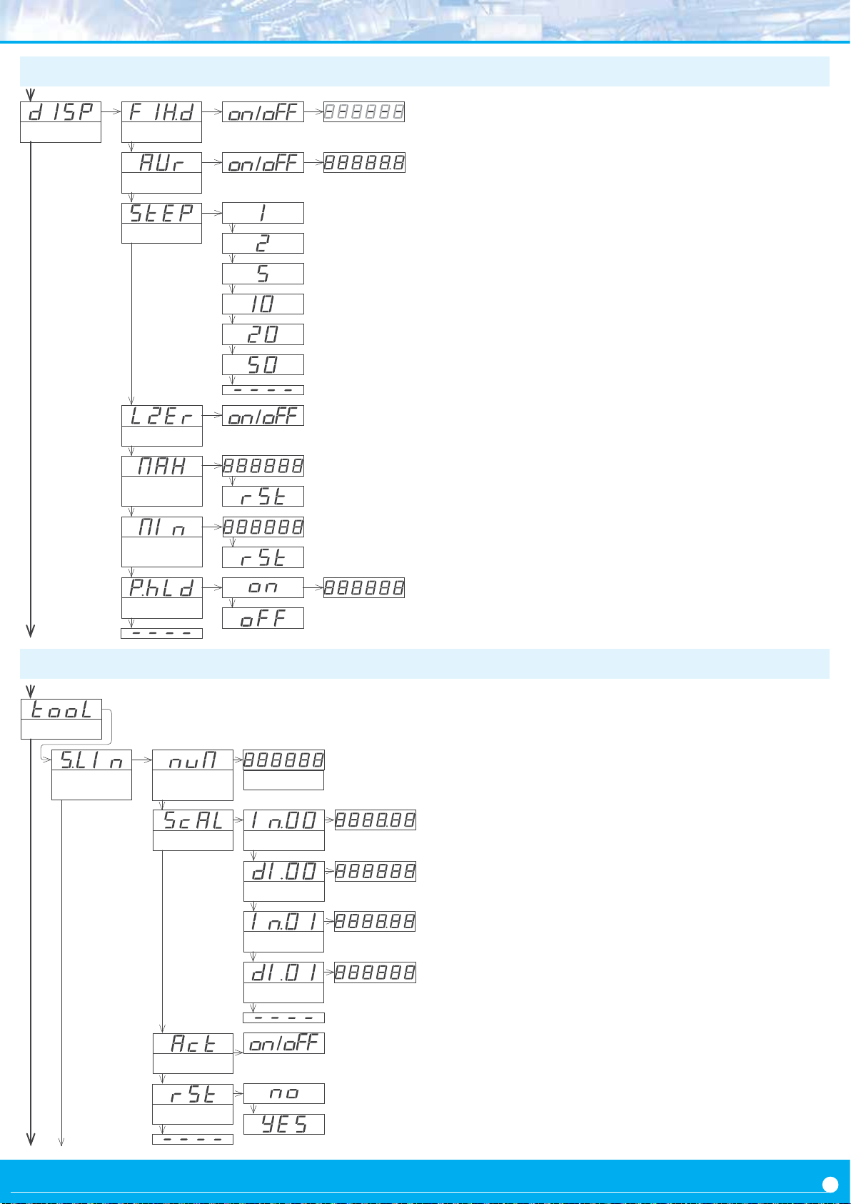
1.12.9 Display lters conguraon menu
Display
Fixed Digits
Fix the digits
All display funcons are grouped under the ‘Display’ menu.
For more informaon relang the funcons listed below see
secon 1.12.7.
Average lter
Steps
Le zeros
Memory of
maximum
Memory of
minimum
0.0 to 99.9
• at the ‘Fixed Digits’ (‘FIX.d’) parameter, x the digits to a
xed value. The ‘-’ value means that the digit is not xed.
• at the ‘Average lter’ (‘Avr’) parameter select ‘on’ and
congure the lter strength between ‘0.0’ and ‘99.9’.
Higher values acvate stronger lter. Stronger lters slow
down the reading changes.
• at the ‘Steps’ (‘StEP’) parameter congure the value for
the steps reading changes.
• at the ‘Le Zeros’ (‘LZEr’) parameter select ‘on’ to
acvate the le zeros.
• the ‘Memory of maximum’ (‘MAX’) and ‘Memory of
minimum’ (‘MIn’) are access to the memory values. To
reset the value, select the ‘rSt’ entry and press ‘SQ’ (<).
• at the ‘Peak & hold’ (‘P.hLd’) menu select ‘on’ to acvate
the funcon and congure the ‘hold’ me.
Peak & Hold
1.12.10 Tools conguraon menu
Tools
Segment
linearizaon
Number of
segments
Scaling
Acvate
Reset
Value 2 to 20
Input 0
Display 0
Input 1
Display 1
Time (Sec.)
Inside the ‘Tools’ (‘tooL’) menu several dierent funcons
are grouped.
At the ‘Segment Linearizaon’ (‘S.LIn’) dene up to
20 segments to linearize non-linear signals. See secon
1.12.8 for more informaon.
• at the ‘Number of segment’ (‘nuM’) parameter
introduce the number of segments. Value between
‘2’ and ‘20’.
• at the ‘Scaling’ (‘ScAL’) parameter introduce the input
signal valur (‘Input’) and the associated reading value
(‘Display’) for each point, starng at point ‘0’, up to the
total number of segments previously dened..
• select ‘Acvate’ (‘Act’) to ‘on’ to acvate the
segments previously congured. Select ‘oFF’ to disable the
segment linearizaon and return to standard scaling
(see secon 1.12.2)
• select ‘Reset’ (‘rSt’) to ’yES’ deletes the actual segment
linearizaon.
15
Page 17

1.12.11 Fast access
The ‘fast access’ is an operator congurable menu. The
operator can access this menu with a single press of the front
key ‘UP’ (5). The congured menu entries will be accessible.
Eligible parameters to be accessed by this menu are:
• access to the alarm setpoints through the ‘UP’ (5) key
allows to read and modify the values.
• access to the maximum and minimum alarms through the
‘UP’ (5) key allows to read and reset the values. To reset
the memory values: visualize the value on display, press the
‘UP’ (5) key, when the ‘rSt’ message appears, press ‘SQ’
(<) . The instrument will return to the memory visualiza
on. Press the ‘LE’ (3) key to exit his menu.
• access to the ‘tare’ parameter through the ‘UP’ (5) key
allows to visualize the value (in display counts) of the tare
applied (see secon 1.12.14).
• access to the ‘measure’ funcon through the ‘UP’ (5)
key visualizes the actual signal at input terminals, without
scaling, directly in mA or Vdc value. The ‘measure’ funcon
provides a direct ‘voltmeter’ or ‘miliammeter’ integrated
into the instrument, to be used for troubleshoong. It helps
to easily conrm if the received signal is correct or not.
The ‘fast access’ menu is not aected by the password
funcon. This means that the conguraon menu can be
password blocked, while some congured funcons or
parameters can sll be accessible to the operator through the
‘fast access’ menu.
• Super fast access
If only a single funcon is selected for the ‘fast access’ menu,
-
pressing the the ‘UP’ (5) key will shortly display the funcon
name and then automacally jump to the funcon value.
1.12.12 ‘on power up’ funcon
The ‘On Power Up’ (‘on.Pu’) funcons allows to dene a
series of acons to acvate when the instrument restarts
aer a power loss. Funcons available are a delay so the
instrument waits a dened me before starng to measure
and control, and an automac tare of the reading. The funcons will apply only aer a restart due to power-loss, they
will not apply aer a restart due to changes in conguraon.
Delaying the measure and control funcons gives addional
me to elements of the system who are slower, so they can
start completely before the instrument begins to acquire
signal and control the outputs.
While on delay mode, the instrument shows all decimal
points lightened and ashing, all alarms are deacvated, and
there is no signal acquision or communicaons control.
When the delay me is over, the instrument starts its normal
funconing.
1.12.14 ‘Tare’ funcon
The ‘Tare funcon’ (‘tArE’) allows to use the instrument with
weight applicaons. The tare funcon assigns the actual
input signal value to a display of ‘0’, by means of an internal
oset. The scaling of the instrument is not modied, only
addional counts are added to the oset.
The tare funcon is accessible through the front ‘LE’ (3)
key (see secon 1.12.13). The actual value of the tare is
accessible through the front ‘UP’ (5) key (see secon
1.12.11). To reset the tare to ‘0’ counts acvate the ‘reset’
parameter of the ‘tare’ menu
1.12.13 ‘LE’ key
The ‘LE’ (3) key at the front of the instrument can be congured to acvate several funcons. Only one funcon can be
assigned to the ‘LE’ (3) key. Eligible funcons are the ‘tare’
funcon (see secon 1.12.14) and the alarm unlock funcon
(see secon 1.12.4).
16
1.12.15 Excitaon voltage
The ‘Excitaon Volt’ (‘V.EXc’) allows to select the excitaon
voltage value to 5 Vdc, 10 Vdc, 15 Vdc or 20 Vdc. Select ‘oFF’
to disable the excitaon voltage.
Page 18
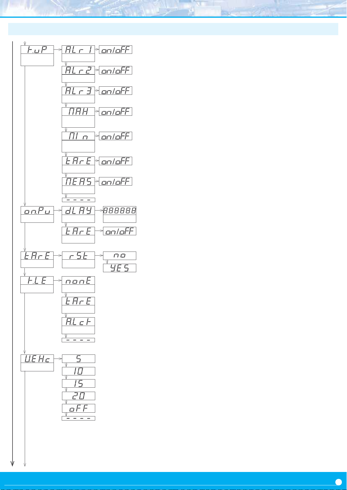
Key UP
(‘Fast access’)
Setpoint 1
Setpoint 2
At the ‘Key UP (‘fast access’)’ (‘K.uP’) menu congure which
funcons and parameters will be accessible through the ‘fast
access’ menu. Select ‘on’ to acvate each funcon. For more
informaon see secon 1.12.11.
• the ‘Setpoint
1’ (‘ALr1’) funcon allows to visualize and
modify the alarm 1 setpoint through the ‘fast access’ menu.
On Power-Up
Tare funcon
Setpoint 3
Memory of
maximum
Memory of
minimum
‘Tare’ value
‘Measure’
Delay
Tare
Reset
Seconds
• the ‘Setpoint
2’ (‘ALr2’) funcon allows to visualize and
modify the alarm 2 setpoint through the ‘fast access’ menu.
• the ‘Setpoint
3’ (‘ALr3’) funcon allows to visualize and
modify the alarm 3 setpoint through the ‘fast access’ menu.
• the ‘Memory of maximum’ (‘MAX’) or ‘Memory of
minimum’ (‘MIn’) funcons allow to visualize the
maximum or minimum reading value stored in memory.
• the ‘tare value’ (‘tArE’) allows to visualize the value of
the applied tare.
• the ‘Measure’ (‘MEAS’) funcon allows to visualize the
actual input signal in mA or Vdc, without scaling.
The ‘On Power Up’ (‘on.Pu’) menu assigns funcons to be
applied when the instrument starts aer a power loss.
For more
informaon see secon 1.12.12.
• at the ‘Delay’ (‘dLAy’) parameter congure the me the
instrument will wait before starng normal funconality.
Time between 0 and 200 seconds.
• at the ‘tare funcon’ (‘tArE’) parameter select ‘on’ to
acvate an automac tare every me the instrument starts
aer a power loss..
Key ‘LE’
Excitaon Volt.
No funcon
Tare
Alarm unlock
5 Vdc
Vdc
10
Vdc
15
Vdc
20
Disabled
• the ‘Tare’ (‘tArE’) allows to reset the value of the tare.
See secon 1.12.14 for more informaon on the ‘tare’
funcon..
The ‘LE’ (3) key at the front of the instrument can be
congured to acvate several funcons. For more
informaon see secon 1.12.13.
• the ‘No funcon’ (‘nonE’) parameter assigns no funcon.
• the ‘Tare’ (‘tArE’) parameter assigns the tare funcon.
• the ‘Alarm unlock’ (‘A.Lck’) parameter assigns the manual
alarm unlocking, when the ‘Locked alarms’ (‘A.Lck’) is acve
(see secon 1.12.4).
At the ‘Excitaon Volt.’ (‘V.EXc’) menu select the excitaon
voltage of the instrument. For more informaon see secon
1.12.15.
17
Page 19
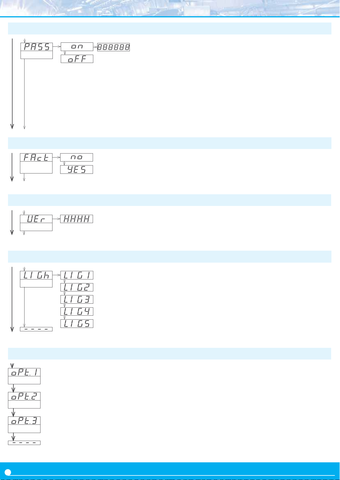
1.12.16 Password conguraon
Password
1.12.17 Default factory conguraon
Factory
conguraon
The password funcon blocks access to the conguraon
menu. The ‘fast access’ menu is not aected by the password
funcon. This means that the conguraon menu can be
password blocked, while some congured funcons or parameters can sll be accessible to the operator through the ‘fast
access’ menu.
To acve the ‘Password’ funcon select ‘on’ and introduce
the 6 digits code. The code will be requested when trying to
access the ‘conguraon menu’ (front key ‘SQ’ (<)).
At the ‘FActory conguraon’ (‘FAct’) menu select ‘yes’ to
acvate the default factory conguraon. See secon 1.13
for a list of default parameters.
1.12.18 Firmware version
The ‘Version’ (‘VEr’) menu informs about the rmware
Version
version installed on the instrument.
1.12.19 Brightness conguraon
Minimum
Brightness
Standard
Maximum
At the ‘Brightness’ (‘LIGh’) menu select the intensity level
for the display . Use this funcon to adapt the brightness to
match other instruments in the vicinity or to the darkness or
clarity of your environment.
1.12.20 Access to the opons conguraon menu
The output and control opons are oponal modules that
can be installed at the instrument. Formats LDB-24 and LDB44 have 2 free slots for output and control opons, while
formats LDB-26 and LDB-46 have 3 free slots (see secon
1.4).
Several of these oponal modules have their own congura
on menu embedded. The ‘OPt.1’, ‘ OPt.2’ and ‘OPt.3’ menu
entries give access to the conguraon menu of the opon
installed.
Opon 1
Opon
Opon 3
Access to the oponal module installed at slot 1
Access to the oponal module installed at slot 2
2
Access to the oponal module installed at slot 3
-
18
See secon 2 for a list of available output and control
modules
Page 20
1.13 Factory conguraon
1.14 Messages and errors
Range 4/20 mA
Scaling and decimal point 4/20 mA = 0/100.0
Alarms 1,2 and 3
Acve o (disabled)
Type as maximum
Setpoint 1000
Hysteresis 0 counts
Acvaon delay 0.0 seconds
Deacvaon delay 0.0 seconds
Setpoint 2 o
Inverted relay o
Locked alarms o
Display
Fixed digits o
Average o
‘Steps’ o
Le zeros o
Maximum memory -199999
Minimum memory 999999
‘Peak&Hold’ o
Tools
Segment linearizaon o
Fast access o
‘On Power Up’
Delay 0 seconds
Tare o
Ley ‘LE’ no funcon
Excitaon voltage +20 Vdc
Password o
Brightness 3
Error messages are informed ashing on display (examples
for 6 digit formats).
Messages and errors
‘h.udr’
‘h.oVr’
‘d.udr’
‘d.oVr’
‘hoLd’ the ‘hold’ funcon is acve. Display is on hold.
‘P.hLd’ the ‘Peak&Hold’ funcon is acve.
‘Err.0’* at the ‘scaling’ (‘ScAL’) menu entry, the dened
‘Err.1’ incorrect password.
‘Err.2’ when accessing an ‘oPt.X’ menu entry, the
‘Err.3’ at ‘segment linearizaon’ (‘SLin’) menu
‘Err.5’* at the ‘segment linearizaon’ (‘SLin’) menu
hardware underrange (‘h.udr’) / overrange (‘h.
ovr’). Input signal is lower / higher than the
minimum / maximum signal the instrument can
detect.
display underrange (‘d.udr’) / overrange (‘d.
ovr’). The display is displaying the maximum /
minimum value possible (-199999 / 999999).
slope is higher than ‘5000’ (slope almost
vercal) or higher than 10000 for 6 digit
formats. Default values are acvated.
*Slope= [(dhI-dLo) / (IhI-ILo)]
installed module can not be recognized.
entry, the input signal values are not in growing
succession.
entry, the dened slope of one segment is
higher than ‘5000’ (slope almost vercal) or
higher than 10000 for 6 digit formats.
*Slope= [(dhI-dLo) / (IhI-ILo)]
‘Err.8’ excitaon voltage overload.
Table 12 - Messages and error codes
19
Page 21
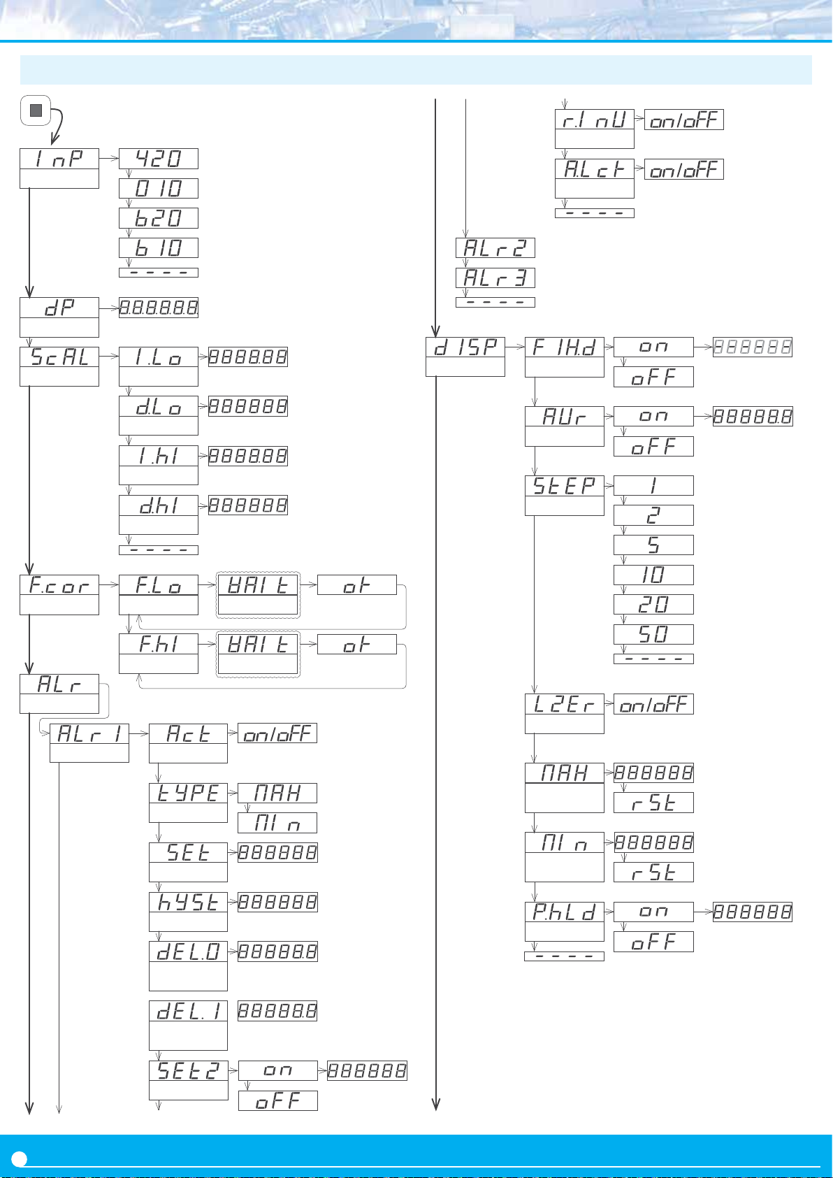
1.15 Full conguraon menu
Press ‘SQ’ (<) for 1 second to access the ‘Conguraon menu’.
4/20 mA input signal range
Input
0/10 Vdc input signal range
±20 mA input signal range
Inverted relay
Locked alarm
Decimal point
Scaling
Field correcon
Input Low
Display Low
Input High
Display High
Correcon Low
±10 Vdc input signal range
Wait (5 sec.)
(<)
Display
Alarm 2
Alarm 3
Fixed Digits
Average lter
Steps
0.0 to 99.9
Alarms
Alarm 1
Correcon High
Acve
Alarm type
Setpoint
Hysteresis
Acvaon
delay
Deacvaon
delay
Wait (5 sec.)
(<)
Le zeros
Memory of
maximum
Memory of
minimum
Peak & Hold
Time (sec.)
20
Setpoint 2
Page 22
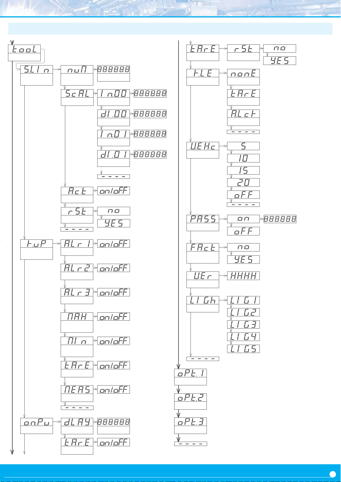
Tools
Tare funcon
Reset
Segment
linearizaon
Number of
segments
Scaling
Acvate
Reset
Value 2 to 20
Input 0
Display 0
Input 1
Display 1
Key ‘LE’
Excitaon Volt.
Password
No funcon
Tare
Alarm unlock
Key UP
(‘Fast access’)
Setpoint 1
Setpoint 2
Setpoint 3
Memory of
maximum
Memory of
maximum
Tare value
‘Measure’
Factory
conguraon
Firmware version
Minimum
Brightness
Standard
Maximum
Access to the oponal module installed at slot 1
Opon 1
Access to the oponal module installed at slot 2
Opon 2
On Power-Up
Delay
Tare
Seconds
Access to the oponal module installed at slot 3
Opon 3
21
Page 23
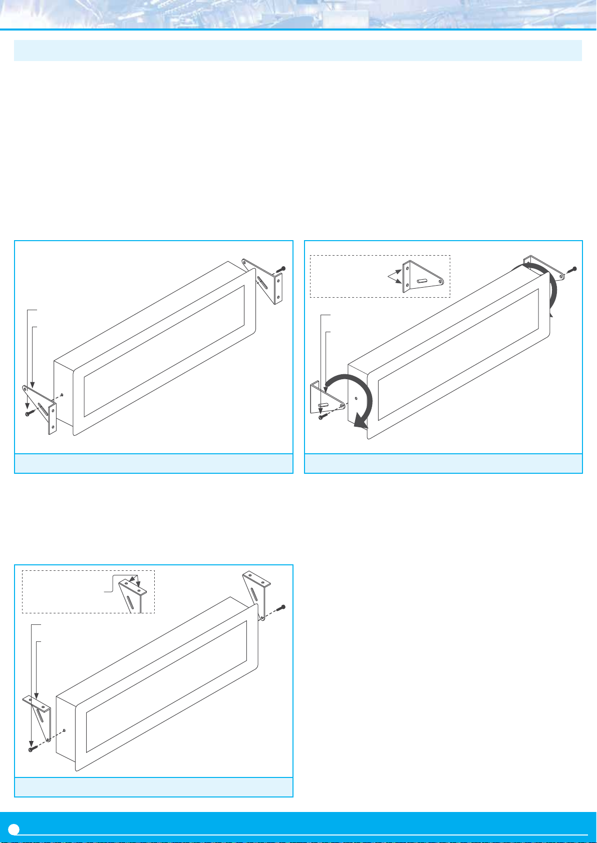
1.16 Mounng
The instrument xaons are designed to allow panel mount,
wall mount, or hanging mount. For each type of mounng,
• Panel mount. Apply the cut-out to the panel as seen on
secon 1.4. Remove the side xaons. Introduce the
instrument into the panel cut-out. Mount the side xaons
as shown (see Figure 12). Slightly loosen the xaon screw
of one side and press the instrument against the panel.
Tighten the xaon screw so it presses the panel and
maintains the xaon. Repeat with the opposite side
xaon. For IP65 protecon at the panel juncon, see the
IPB accessories at secon 3.
Fixaon screws
Side xaons
see the posion of the xaons at the images below.
• Wall mount. Mount the side xaons against the wall,
as shown (see Figure 14). Each xaon has 2 holes with
4,5 mm diameter and a separaon between hole centers
of 30 mm. Once the side xaons are secured against the
wall, place the instrument and press the xaon screws
slightly. Tilt the instrument to the desired viewing angle
and rmly screw the xaon screws.
Diameter 4,5 mm
30 mm between
hole centers
Fixaon screws
Side xaons
Figure 12 - Panel mount
• Hanging mount. Mount the side xaons as shown
(see Figure 13). Each xaon has 2 holes with 4,5 mm
diameter and a separaon between hole centers of 30 mm.
Instrument can be hanged using cable, threaded rod, ....
Diameter 4,5 mm
30 mm between
hole centers
Fixaon screws
Side xaons
Figure 14 - Wall mount
Figure 13 - Hanging mount
22
Page 24
1.17 Installaon precauons
1.19 CE declaraon of conformity
Risk of electrical shock. Instrument terminals can be
connected to dangerous voltage.
Instrument conforms to CE rules and regulaons.
This instrument has been designed and veried conforming to
the 61010-1 CE security regulaon, for industrial applicaons.
Installaon of this instrument must be performed by
qualied personnel only. This manual contains the appropriate
informaon for the installaon. Using the instrument in ways not
specied by the manufacturer may lead to a reducon of the
specied protecon level. Disconnect the instrument from
power before starng any maintenance and / or installaon
acon.
The instrument does not have a general switch and will start
operaon as soon as power is connected. The instrument
does not have protecon fuse, the fuse must be added during
installaon.
An appropriate venlaon of the instrument must be assured.
Do not expose the instrument to excess of humidity. Maintain
clean by using a humid rag and do NOT use abrasive products
such as alcohols, solvents, etc.
General recommendaons for electrical installaons apply, and
for proper funconality we recommend : if possible, install the
instrument far from electrical noise or magnec eld generators such as power relays, electrical motors, speed variators,
... If possible, do not install along the same conduits power cables (power, motor controllers, electrovalves, ...) together with
signal and/or control cables.
Before proceeding to the power connecon, verify that the
voltage level available matches the power levels indicated in
the label on the instrument.
In case of re, disconnect the instrument from the power line,
re alarm according to local rules, disconnect the air condioning, aack re with carbonic snow, never with water.
Supplier Omega Engineering
Products LDB-P
The manufacturer declares that the instruments indicated
comply with the direcves and rules indicated below.
Electromagnec compability direcve 2014/30/EU
Low voltage direcve 2014/65/EU
Direcve ROHS 2011/65/EU
Direcve WEEE 2012/19/EU
Security rules EN-61010-1
Instrument Fixed, Permanently connected
Polluon degree 1 and 2 (without condensaon)
Isolaon Basic + Protecve union
Category CAT-II
Electromagnec compability rules EN-61326-1
EM environment
Immunity levels
EN-61000-4-2
EN-61000-4-3
EN-61000-4-4
EN-61000-4-5
EN-61000-4-6
EN-61000-4-8 30 A/m at 50/60 Hz
EN-61000-4-11 0 % 1 cycle
40 % 10 cycles
70 % 25 cycles
0 % 250 cycles
Emission levels
CISPR 11 Instrument Class A, Group 1
Industrial
By contact
By air
On AC power lines
On DC power lines
On signal lines
Between AC power lines
Between AC power lines and earth
Between DC power lines
Between DC power lines and earth
Between signal lines and earth
±4 KV
±8 KV
: ±2 KV
: ±2 KV
: ±1 KV
±1 KV
±1 KV
±2 KV Criteria
±2 KV
±1 KV
Criteria
Criteria
Criteria
Criteria
Criteria
Criteria
Criteria
Criteria
Criteria
Criteria
Criteria
Criteria
Criteria
Criteria
Criteria
Criteria
Criteria
B
B
A
B
B
B
B
B
B
B
B
A
A
A
A
B
B
A
1.18 Warranty
Please see the last page for Omega’s warranty Disclaimer
According to direcve 2012/19/EU, electronic
equipment must be recycled in a selecve and
controlled way at the end of its useful life.
23
Page 25
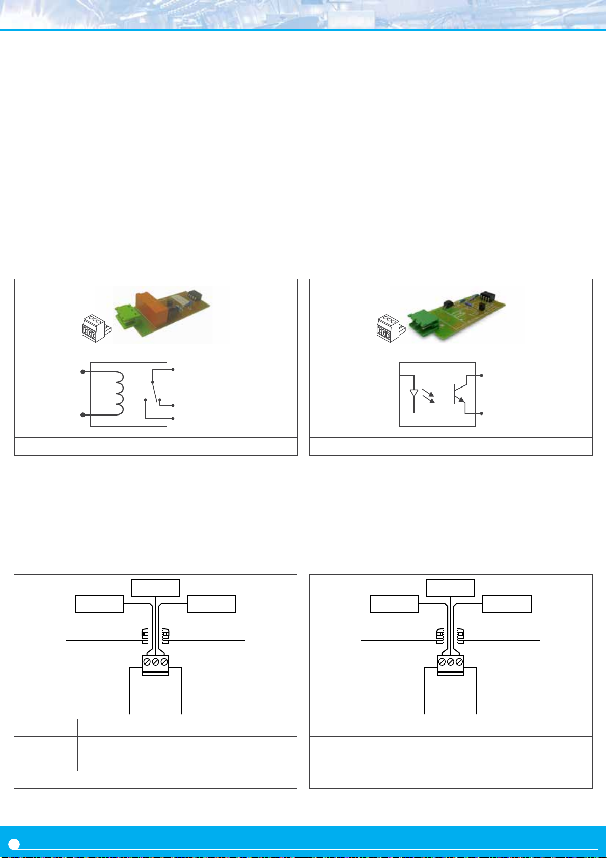
2. Output and control modules
2.1 Module R1
The R1 module provides 1 relay output to install in large
format industrial meters from LDB series. Formats LDB-26 and
LDB-46 accept up to 3 relays, and formats LDB-24 and LDB-44
accept up to 2 relays.
Conguraon is performed from the front keypad of the
instrument, by seng the alarm parameters. Check the alarm
menu parameters at the instrument user’s manual for full
informaon.
Modules R1 can be provided factory installed into
instrument, or standalone for delayed installaon. No
soldering or special conguraon is required. See secon 1.6
on how to install output and control modules.
‘com’ (‘A’)
2.2 Module T1
The T1 module provides 1 transistor output to install in large
format industrial meters from LDB series. Formats LDB-26 and
LDB-46 accept up to 3 transistor outputs, and formats LDB-24
and LDB-44 accept up to 2 transistor outputs.
Conguraon is performed from the front keypad of the
instrument, by seng the alarm parameters. Check the alarm
menu parameters at the instrument user’s manual for full
informaon.
Modules T1 can be provided factory installed
instrument, or standalone for delayed installaon. No
soldering or special conguraon is required. See secon 1.6
on how to install output and control modules.
‘B’
‘NC’ (‘C’)
‘NO’ (‘B’)
Figure 15 - Module ‘R1’ and internal schemac
Type of relay 3 contacts (Com, NO, NC)
Max. current 3 A (resisve load)
Voltage 250 Vac connuous
Isolaon 3500 Ve
Terminal plug-in screw clamp, pitch 5.08 mm
Installaon allowed at
slot 1, slot 2, slot 3
NOpen
NClosedCommon
CBA
Module R1
‘A’
Figure 17 - Module ‘T1’ and internal schemac
Type of output transistor
Max. voltage 35 Vdc
Max. current 50 mA
Isolaon 3500 Ve, optoisolated
Terminal plug-in screw clamp, pitch 5.08 mm
Installaon allowed at
slot 1, slot 2, slot 3
B
A
CBA
Module T1
Not connected
A Common
B NO (Normally Open)
C NC (Normally Closed)
Figure 16 - Connecons for ‘R1’ relay output module
24
A Emier
B Collector
C Not connected
Figure 18 - Connecons for ‘T1’ transistor output module
Page 26
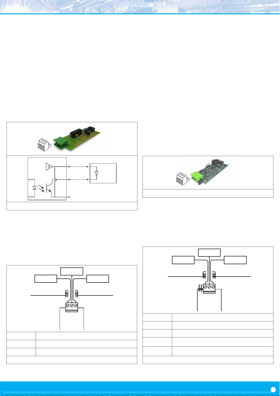
2.3 Module SSR
2.4 Module AO
The SSR module provides 1 output for SSR relay control, to
install in large format industrial meters from LDB series. For
mats LDB-26 and LDB-46 accept up to 3 SSR control outputs,
and formats LDB-24 and LDB-44 accept up to 2 SSR control
outputs.
Conguraon is performed from the front keypad of the
instrument, by seng the alarm parameters. Check the alarm
menu parameters at the instrument user’s manual for full
informaon.
Modules SSR can be provided factory installed instrument, or
standalone for delayed installaon. No soldering or special
conguraon is required. See secon 1.6 on how to install
output and control modules.
+15 Vdc
‘C’
Relé SSR
The AO module provides 1 analog output, congurable for
-
4/20 mA or 0/10 Vdc signal, to install in large format industrial
meters from LDB series. Formats LDB-26 and LDB-46 accept
up to 3 analog outputs, and formats LDB-24 and LDB-44 ac
cept up to 2 analog outputs.
Output signal is fully scalable, both with posive and negave
slopes, and is proporonal to the reading. The mA output can
be congured for acve loops (the instrument provides the
power to the mA loop) or passive loops (the loop power is
external to the instrument).
Conguraon is performed from the front keypad of the in
strument, by accessing the menu entries ‘Opt.1’, ‘Opt.2’ or
‘Opt.3’, according to the slot where the module is installed.
AO modules can be provided factory installed into the LDB
series instrument, or standalone for delayed installaon. No
soldering or special conguraon is required. See secon 1.6
on how to install output and control modules.
-
-
‘B’
‘A’
Figure 19 - Module ‘SSR’ and internal schemac
Type of output for SSR relay control
Output voltage +15 Vdc
Max. current 45 mA
Isolaon 1000 Vdc
Terminal plug-in screw clamp, pitch 5.08 mm
Installaon allowed at
Not connected
slot 1, slot 2, slot 3
Collector
+15 Vdc
CBA
Figure 21 - Module ‘AO’
Signal output 4/20mA, 0/10Vdc (acve and passive)
Accuracy 0.1% FS
Isolaon 1000 Vdc
Terminal plug-in screw clamp, pitch 5.08 mm
Installaon allowed at
Jumpers MV for
mA or Vdc out-
put selecon
slot 1, slot 2, slot 3
mA or Vdc
M
V
CBA
Module AO
CommonV exc.
Module SSR
A Not connected
B Collector (-)
C +15 Vdc (+)
Figure 20 - Connecons for ‘SSR’ control module
A Excitaon voltage
B Signal in mA or Vdc
C Common
Jumper M Jumper closed for mA output
Jumper V Jumper closed for Vdc output
Figure 22 - Connecons for ‘AO’ analog output module
25
Page 27
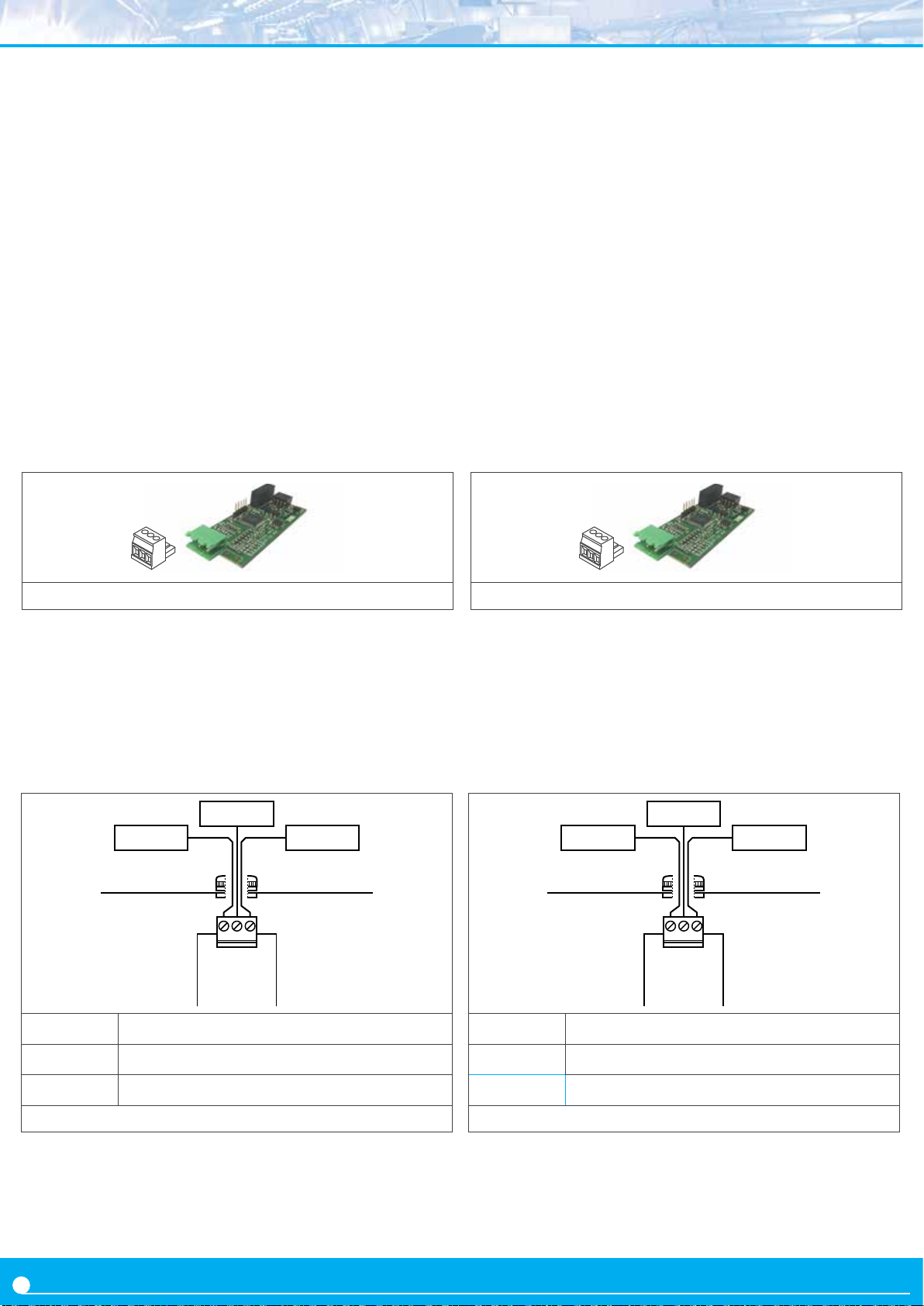
2.5 Module RTU
The RTU module provides an isolated Modbus RTU
communicaons port, to install in large format industrial
meters from LDB series.
2.6 Module S4
The S4 module provides an isolated RS485 ASCII
communicaons port, to install in large format industrial
meters from LDB series.
The RTU module implements funcon ‘4’ (‘Read Input
Registers’) of the Modbus RTU protocol, to access the
instrument registers (reading value, alarm status, memory of
maximum and minimum, ...).
Conguraon is performed from the front keypad of the
instrument, by accessing the menu entries ‘Opt.1’, ‘Opt.2’ or
‘Opt.3’, according to the slot where the module is installed.
Modules RTU can be provided factory installed into the
LDB series, or standalone for delayed installaon. No
soldering or special conguraon is required. See secon 1.6
on how to install output and control modules.
Figure 23 - Communicaons module ‘RTU’
The S4 module implements a MASTER / SLAVE protocol, with
up to 31 addressable slaves. In SLAVE mode allows access
to reading values, alarm status, memory of maximum and
minimum, ...
Conguraon is performed from the front keypad of the
instrument, by accessing the menu entries ‘Opt.1’, ‘Opt.2’ or
‘Opt.3’, according to the slot where the module is installed.
Modules S4 can be provided factory installed into the
LDB series, or standalone for delayed installaon. No
soldering or special conguraon is required. See secon 1.6
on how to install output and control modules.
Figure 25 - Communicaons module ‘S4’
Protocol Modbus RTU
Bus RS-485, up to 57.6 Kbps
Isolaon 1000 Vdc
Terminal plug-in screw clamp, pitch 5.08 mm
Installaon allowed at
slot 1, slot 2, slot 3
A wire
GNDB wire
GAB
Module RTU
A Bus signal A
B Bus signal B
G GND
Protocol ASCII
Bus RS-485, up to 57.6 Kbps
Isolaon 1000 Vdc
Terminal plug-in screw clamp, pitch 5.08 mm
Installaon allowed at
slot 1, slot 2, slot 3
A wire
GNDB wire
GAB
Module S4
A Bus signal A
B Bus signal B
G GND
Figure 24 - Connecons for Modbus ‘RTU’ communicaons module
26
Figure 26 - Connecons for RS-485 ‘S4’ communicaons module
Page 28
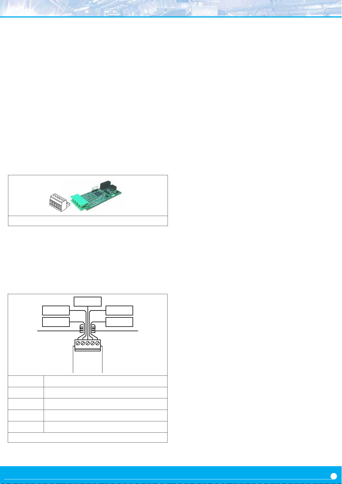
2.7 Module S2
The S2 module provides an isolated RS232 ASCII
communicaons port, to install in large format industrial
meters from LDB series.
The S2 module implements a MASTER / SLAVE protocol, with
up to 31 addressable slaves, with ‘daisy-chain’ connecon.
In SLAVE mode allows access to reading values, alarm status,
memory of maximum and minimum, ...
Conguraon is performed from the front keypad of the
instrument, by accessing the menu entries ‘Opt.1’, ‘Opt.2’ or
‘Opt.3’, according to the slot where the module is installed.
Modules S2 can be provided factory installed into the
LDB series, or standalone for delayed installaon. No
soldering or special conguraon is required. See secon 1.6
on how to install output and control modules.
Figure 27 - Communicaons module Module ‘S2’
Protocol ASCII
Bus RS-232, up to 57.6 Kbps
Isolaon 1000 Vdc
Terminal plug-in screw clamp, pitch 5.08 mm
Installaon allowed at
A
B
C
D
slot 1, slot 2, slot 3
Tx1
Rx1Rx2
Tx2
D
CBA
Module S2
GND
E
‘Daisy chain’ Tx data transmission
‘Daisy chain’ Rx data recepon
Tx data transmission
Rx data recepon
E GND
Figure 28 - Connecons for RS-232 ‘S2’ communicaons module
27
Page 29

28
Page 30

29
Page 31
Opons and Accessories
Index
1.1 Read this rst . . . . . . . . . . . . . . . . . . 2
1.2 Modular architecture . . . . . . . . . . . . . . 2
1.3 Installaon and start-up . . . . . . . . . . . . 2
1.4 To access the instrument . . . . . . . . . . . . 3
1.5 Modular system . . . . . . . . . . . . . . . . . 3
1. Opons R1, T1 and SSR . . . . . . . . . . . . . . 4
1.1 Module R1 . . . . . . . . . . . . . . . . . . . . 4
1.2 Module T1 . . . . . . . . . . . . . . . . . . . . 4
1.3 Module SSR . . . . . . . . . . . . . . . . . . . 5
2. Opon AO . . . . . . . . . . . . . . . . . . . . . . 6
2.1 Connecon examples. . . . . . . . . . . . . . 6
2.2 Conguraon menu. . . . . . . . . . . . . . . 7
2.3 Error codes . . . . . . . . . . . . . . . . . . . 7
3. Opon
3.1 Registers accessible through Modbus RTU . . 8
3.2 Conguraon menu. . . . . . . . . . . . . . . 9
RTU . . . . . . . . . . . . . . . . . . . . . . . 8
1.1 Read this rst
All modules menoned in this document are compable with
large format meters from LDB series has 4 formats, and each
format dier in the number of digits, the digit height and the
number of output and control opons they can accept.
This document assumes the following :
3.3 Excepon codes . . . . . . . . . . . . . . . . . 9
3.4 Compable versions . . . . . . . . . . . . . . 9
3.5 Descripon and example of registers . . . . .10
4. Opon
4.1 Accessible registers . . . . . . . . . . . . . . .11
4.2 Conguraon menu. . . . . . . . . . . . . . .12
4.3 Compable versions . . . . . . . . . . . . . .12
4.4 Frame types . . . . . . . . . . . . . . . . . . .13
4.5 Frame structure . . . . . . . . . . . . . . . . .13
4.6 Error codes . . . . . . . . . . . . . . . . . . .13
4.8 Frame examples. . . . . . . . . . . . . . . . .14
4.8.1 Frames ‘RD’ (36) and ‘ANS’ (37) . . . . . .14
4.8.2 Frames ‘ERR’ (38) . . . . . . . . . . . . . .14
4.7.1 Frames ‘PING’ (32) and ‘PONG’ (33) . . . .14
4.7 CRC calculaon . . . . . . . . . . . . . . . . .14
5. Opon
S4 . . . . . . . . . . . . . . . . . . . . . . . .11
S2 . . . . . . . . . . . . . . . . . . . . . . . .15
1.2 Modular architecture
Large displays from the LDB series are designed following
a modular architecture that allows the operator to install
any of the output and control modules menoned in this
document. Each module is supplied with 1 cable e, 1
square self adhesive e base and 1 female connector.
Format Digits Digit height Opons
LDB-24 4 60 mm 2
LDB-44 4 100 mm 2
LDB-26 6 60 mm 3
LDB-46 6 100 mm 3
•
inside the programming menus, when a 6 digits value is shown,
it is assumed that only 4 digits apply to formats LDB-24 and LDB-44
• when this document explains that a maximum of 3 output
and control modules are installable, it is assumed that the
maximum is 2 modules for formats LDB-24 and LDB-44
The output and control modules menoned in this document,
are covered by the warranty of the instrument where they are
installed. Check the user’s manual of the instrument for more
informaon related to warranty.
The user’s manual of the instrument where the module is
installed, has important informaon related to installaon
that applies also to the output and control modules
menoned in this document. Check the user’s manu-
!
al of the instrument for more informaon related to
installaon precauons.
The output and control modules menoned in this document
are covered by the ‘CE declaraon of conformity’ of
the instrument where they are installed. Check the
user’s manual of the instrument for more informaon
related to the CE declaraon of conformity.
1.3 Installaon and start-up
To install an oponal output and control module into a large
display:
1. remove the rear cover of the instrument (see secon 1.4)
2. install the module at one of the free slots (see secon 1.5)
3. place the squared e base at the free slot selected.
Locaon to place the e base is clearly indicated on the PCB
(see secon 1.5).
4. pass the cable e through the e base (see secon 1.5)
5. place the output and control module at the slot connecon
jumpers (see secon 1.5)
6. use the cable e to rmly x the module (see secon 1.5)
7. if needed, congure the appropriate jumpers at the output
and control module
8. pass the connecon wires through the housing cable gland
9. connect the signal wires to the terminals of the output and
control module
10. place and close the rear cover of the instrument (see
secon 1.4)
11. congure the parameters at the ‘Conguraon menu’.
• modules R1, T1 and SSR are congured from the alarms
menu of the instrument
• other modules are congured from from menu entries
‘Opt.1’, ‘Opt.2’ or ‘Opt.3’, depending on the slot where the
module has been installed.
2
Page 32
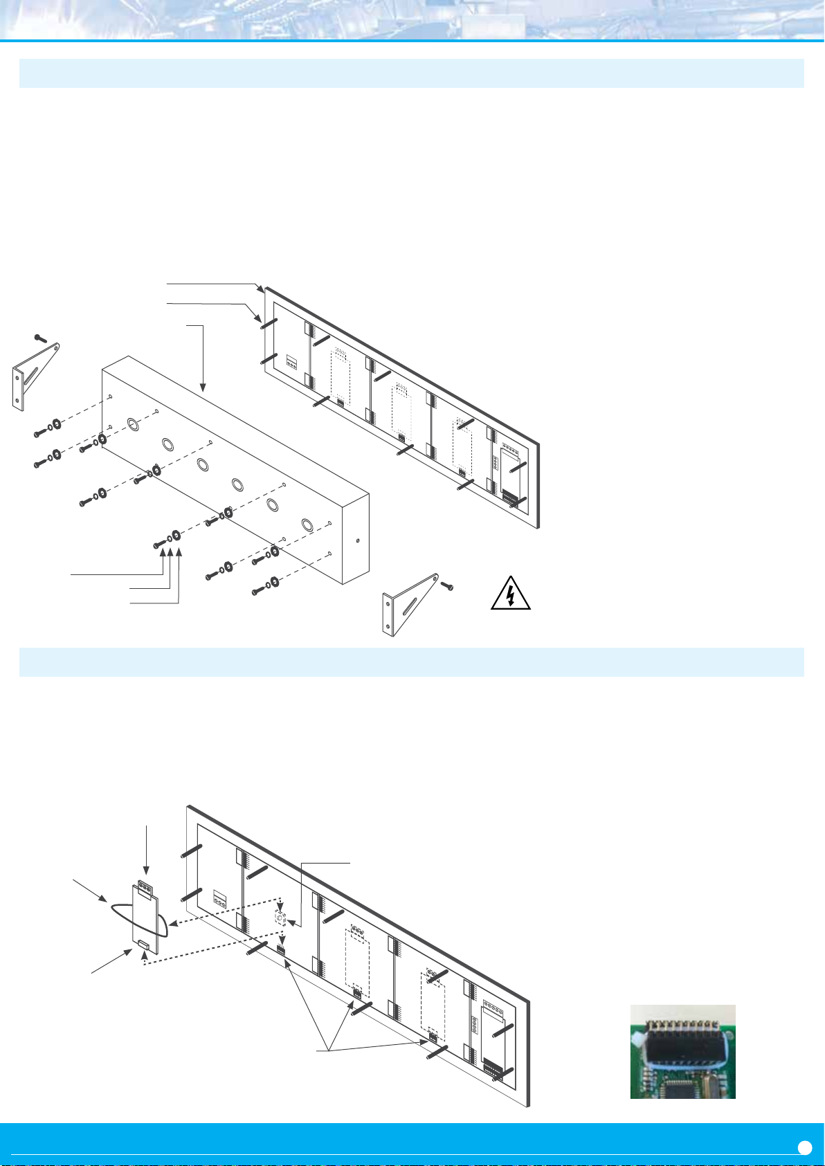
1.4 To access the instrument
To open the housing, remove the screws from the back cover.
With each screw there is a metal washer and a plasc washer.
Once the screws are out, remove the back cover.
The gure below shows the instrument internal structure for a
LDB-26 format. It shows the locaon of the 3 slots for oponal
output and control modules, the power terminal and the input
signal terminal.
Waterght seal
Female turret
Power
Slot for opon 3Back cover
To close the instrument, place the back cover, the screws, the
metal washer and the plasc washer. The plasc washer is in
contact with the back cover. Conrm that the screws are correctly
turning inside the internal female screws.
To ensure a correct IP65 protecon ghten the back cover screws
with a strength between 30 and 40 Ncm, with the help of a
dynamometer screwdriver.
Slot for opon 2
Slot for opon 1
Remote keypad terminal
Input signal terminal
Screw
Metal washer
Plasc washer
1.5 Modular system
Large format meters are designed with an
internal modular architecture. The output and control
modules are independent and can be installed by accessing the internal circuits of the instrument, and connecng
Output and control module
Slot 3
Tie base
Cable e
Slot 2
(2)
(1)
Module pins
Risk of electric shock. Removing the back
cover will grant access to the internal
circuits of the instrument. Operaon must
be performed by qualied personnel only.
the module to the connecon jumpers of the selected slot.
Each module is provided with a cable e to x the module to
the e base. A cable gland to install at the back cover is also
provided, in order to enable an output for the connecon
wires.
To install an output and control module
(1) insert the ‘module pins’ into the ‘con-
necon jumpers’ in one of the free slots
(2) place the ‘cable e’ into the ‘e base’
and embrace the ‘module’ rmly, unl
it is xed
Slot 1
(3) an addional white cable e is provided
to x as indicated below. Only needed in
case of vibraons or heavy transportaon.
Connecon jumpers
3
Page 33
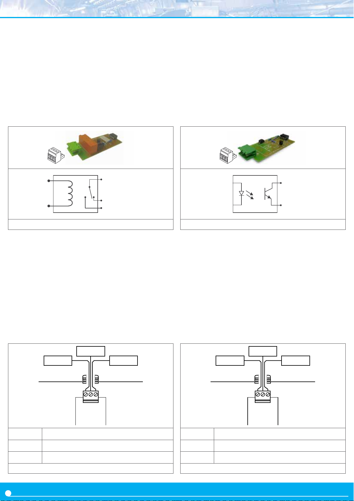
1. Opons R1, T1 and SSR
The R1, T1 and SSR modules provide 1 digital ‘on/o’
output. The output is congured from the instrument
alarms menu (‘ALr.1’, ‘ALr.2’ o ‘ALr.3’).
The menu allows to congure the setpoint, hysteresis,
independent acvaon and deacvaon delays, and a
second setpoint to create windowed alarms.
The R1, T1 and SSR output modules are isolated between
them and between all other circuits of the instrument.
1.1 Module R1 1.2 Module T1
‘com’ (‘A’)
‘NC’ (‘C’)
‘NO’ (‘B’)
Figure 1 - Detail for the ‘R1’ module and internal schemac
Figure 3 - Detail for the ‘T1’ module and internal schemac
‘B’
‘A’
Opon R1
Type of output relay
Type of relay 3 contacts (Com, NO, NC)
Max. current 3 A (resisve load)
Voltage 250 Vac connuous
(max. 150 Vac if switching power network with Overvoltage category III)
Isolaon 3500 Ve
Type of terminal plug-in screw clamp
pitch 5.08 mm
Installaon allowed at slot 1, slot 2, slot 3
NOpen
NClosedCommon
CBA
Opon T1
Type of output transistor
Max voltage 35 Vdc
Max. current 50 mA
Isolaon 3500 Ve, optoisolated
Type of terminal plug-in screw clamp
pitch 5.08 mm
Installaon allowed at slot 1, slot 2, slot 3
B
A
Not connected
CBA
Module R1
A Common
B NO (Normally Open)
C NC (Normally Closed)
Figure 2 - Connecons for the ‘R1’ relay output module
4
Module
A Emier
B Collector
C Not connected
Figure 4 - Connecons for the ‘T1’ transistor output module
T1
Page 34
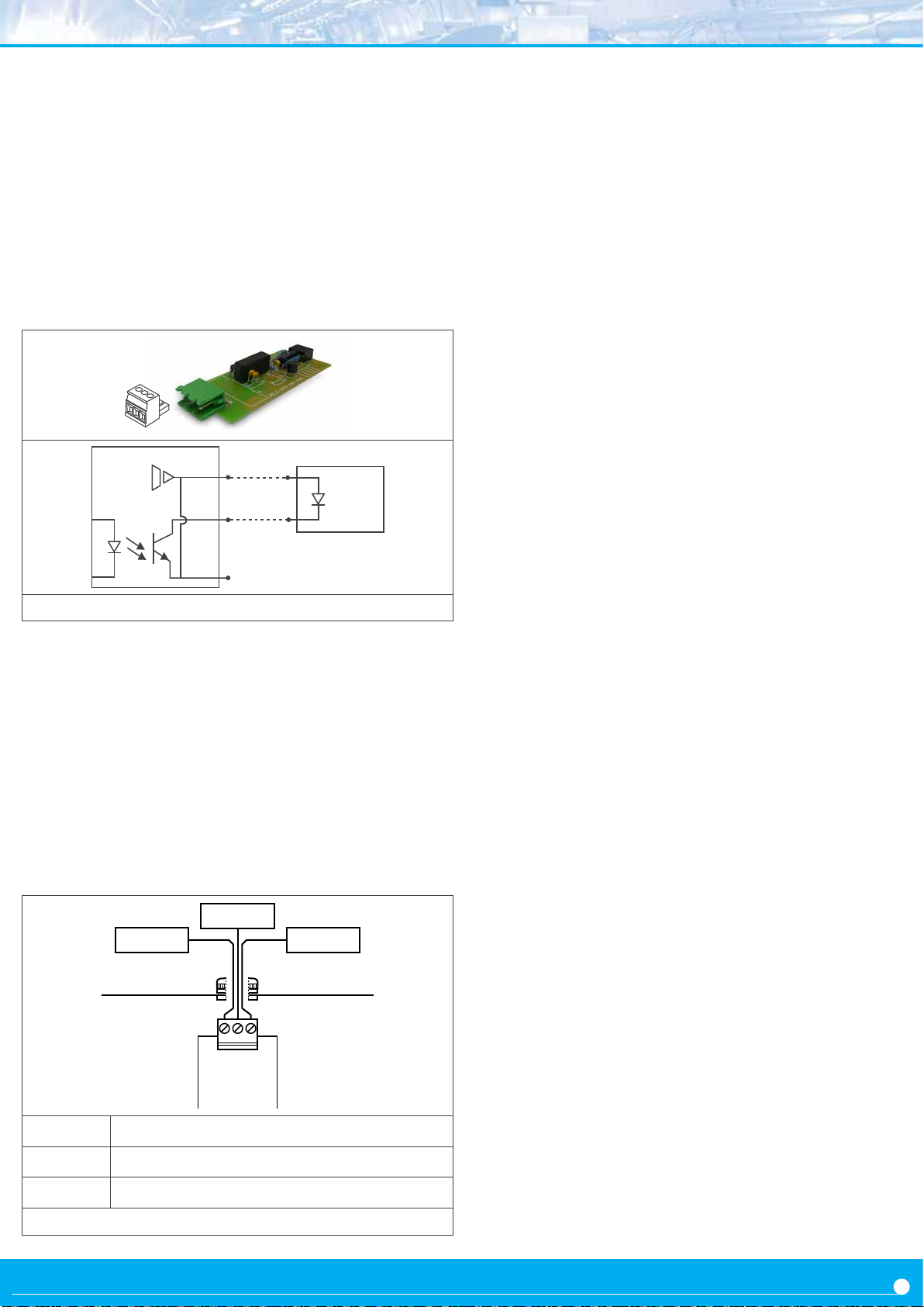
1.3 Module SSR
+15 Vdc
‘C’
Relé SSR
‘B’
‘A’
Figure 5 - Detail for the ‘SSR’ module and internal schemac
Opon SSR
Type of output to control SSR relay
Output voltage +15 Vdc
Max. current 45 mA
Isolaon 1000 Vdc
Type of terminal plug-in screw clamp
pitch 5.08 mm
Installaon allowed at slot 1, slot 2, slot 3
Collector
+15 Vdc
Opt.2
A B C
Opt.3
A B C
Not connected
Opt.1
A B C
CBA
Module SSR
A Not connected
B Collector (-)
Signal
Power
C +15 Vdc (+)
Figure 6 - Connecons for the SSR control output module
5
Page 35
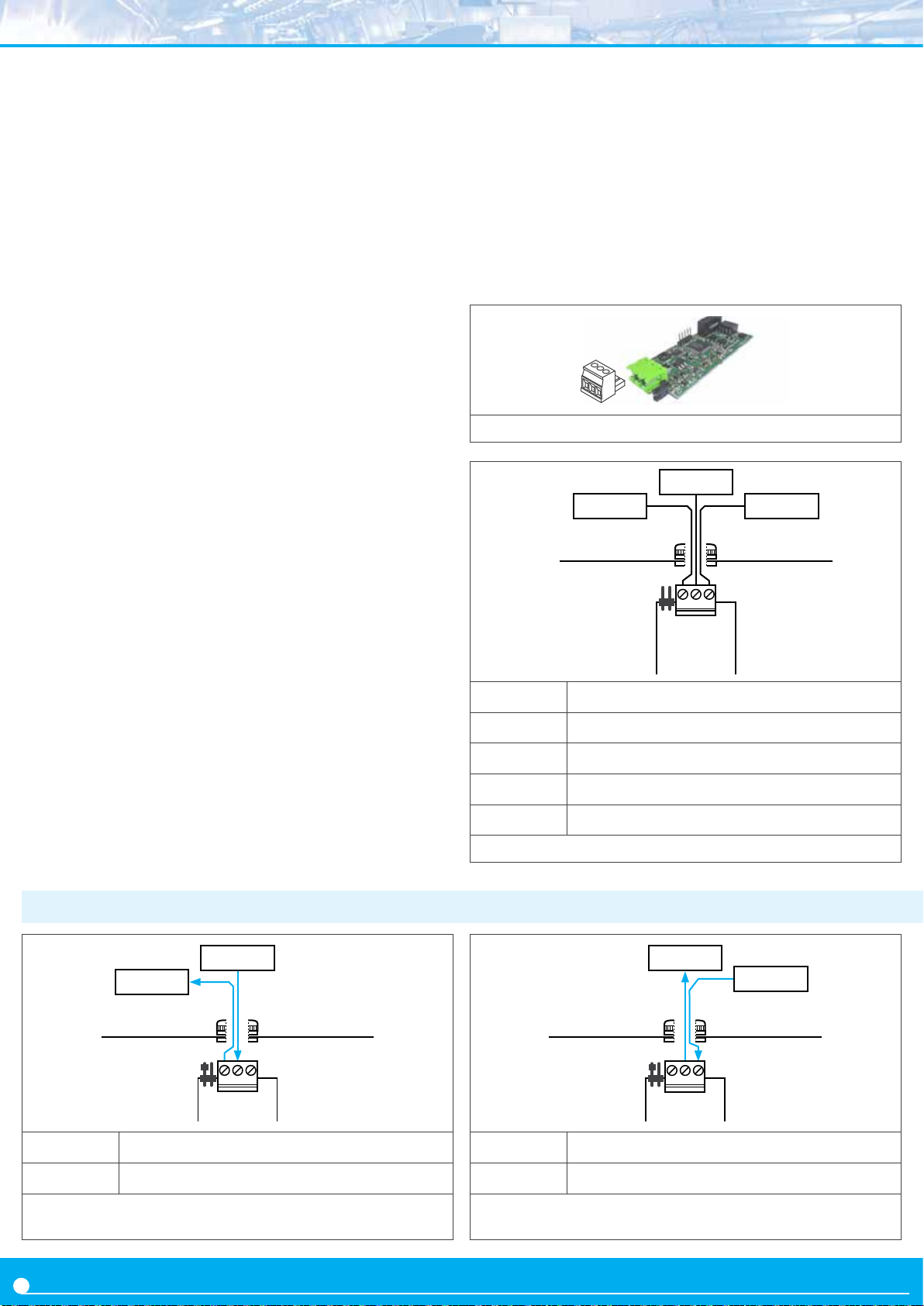
2. Opon AO
The AO modules provide 1 analog output, congurable for
4/20 mA or 0/10 Vdc signal. The analog output is congured
from the opons menu entry (‘Opt.1’, ‘Opt.2’ or ‘Opt.3’) of
the instrument.
Opon AO
Type of output analog output
Signal output 4/20 mA acve
4/20 mA passive
0/10 Vdc
Max. signal 22 mA, 10.5 Vdc
Min. signal 0 mA, -50 mVdc
Scaling proporonal to the reading
posive or negave slopes
Vexc (terminal A) +13.8 Vdc ± 0.4 Vdc (max. 25 mA)
protecon against shortcircuit
Load impedances ≤350 Ohm (for 4/20 mA acve)
≤800 Ohm (for 4/20 mA passive)
(for 24 Vdc external Vexc) (maximum
voltage 27 Vdc between ‘B’ and ‘C’)
≥10 KOhm (en 0/10 Vdc)
Accuracy (at 25 ºC) <0.1 % FS
Thermal stability 60 ppm/ºC in mA
50 ppm/ºC in Vdc
Step response <75 mSeconds + step response of the
(0% to 99% of the signal)
reading
Isolaon 1000 Vdc
Warm up 15 minutes
Type of terminal plug-in screw clamp
pitch 5.08 mm
Factory conguraon ‘Mode mA’
‘Scaling 0/9999 = 4/20 mA’
‘On error ‘to_h’
Installaon allowed at slot 1, slot 2, slot 3
The output signal is proporonal to the reading, and it is
scalable both in posive or negave slopes. The mA output
can be congured for acve loops (the instrument provides
the power to the mA loop) or passive loops (the loop power
is external to the instrument.
The AO analog output modules are isolated between them
and between all other circuits of the instrument.
Figure 7 - Detail for the ‘AO’ module
mA or Vdc
CommonV exc.
Jumpers MV to
select mA or Vdc
output
MV
CBA
Module AO
A Excitaon voltage
B Signal in mA or Vdc
C Common
Jumper M Jumper closed for mA output
Jumper V Jumper closed for Vdc output
Figure 8 - Connecons for ‘AO’ analog output module
2.1 Connecon examples
mA
V exc.
MV
CBA
Module AO
Jumper M Jumper closed
Jumper V Jumper open
Figure 9 - Connecons for acve 4/20 mA. The current loop is
internally powered from the ‘AO’ module
6
+ mA
- mA
MV
CBA
Module AO
Jumper M Jumper closed
Jumper V Jumper open
Figure 10 - Connecons for passive 4/20 mA. The current loop
is externally powered.
Page 36
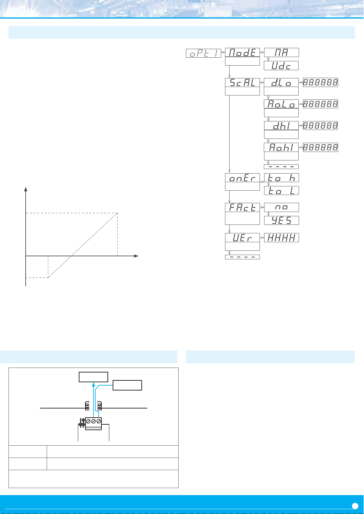
2.2 Conguraon menu
At the ‘Mode’ (‘ModE’) menu congure the type of output
‘4/20 mA’ (‘mA’) or ‘0/10 Vdc‘ (‘Vdc’). Posion for jumpers
‘V’ and ‘M’ must be according to the range selected.
At the ‘Scaling’ (‘ScAL’) menu enter the values that dene
the two points of the slope:
• the lower point, dened by the ‘Low Display’ (‘d.Lo’)
and ‘Low Output’ (‘Ao.Lo’)
• the upper point, dened by the ‘High Display’ (‘d.hI’)
and ‘High Output’ (‘Ao.hI’)
Analog output values are shown with ‘XX.XX’ format.
acceptable values are ‘0.00’ to ‘10.00’ Vdc for voltage, and
‘0.00’ to ‘20.00’ mA for current.
Reading
100.0
Example
associated to a reding of -50.0 to 100.0
- 4/20 mA, analog output
‘d.hI’=‘100.0’
‘Ao.hI’=‘20.00’
Mode
Scaling
‘On error’
Factory
conguraon
Mode 4/20 mA
Mode 0/10 Vdc
Display low
Output low
Display high
Output high
in case of error, ‘to_h’
to drive output to high
level, ‘to_L’ to drive
output to low level
select ‘yES’ to reload
the default factory conguraon
-50.0
4 mA
‘Ao.Lo’=‘4.00’
‘d.Lo’=‘-50.0’
signal Vdc
MV
CBA
Module AO
20 mA
common
Version
Analog
output
2.3 Error codes
‘Er.34’ output signal congured to value lower than 0 Vdc or 0 mA
‘Er.35’ output signal congured to a value higher than 10 Vdc or
20 mA
‘Er.36’ congured slope points are not acceptable, such as :
‘d.Hi’=’d.Lo’
‘Ao.Hi’=’Ao.Lo’
(‘Ao.Hi’-’Ao.Lo’)>(’d.Hi’-’d.Lo’)
Jumper M Jumper open
Jumper V Jumper closed
Figure 11 - Connecons for 0/10 Vdc.
7
Page 37
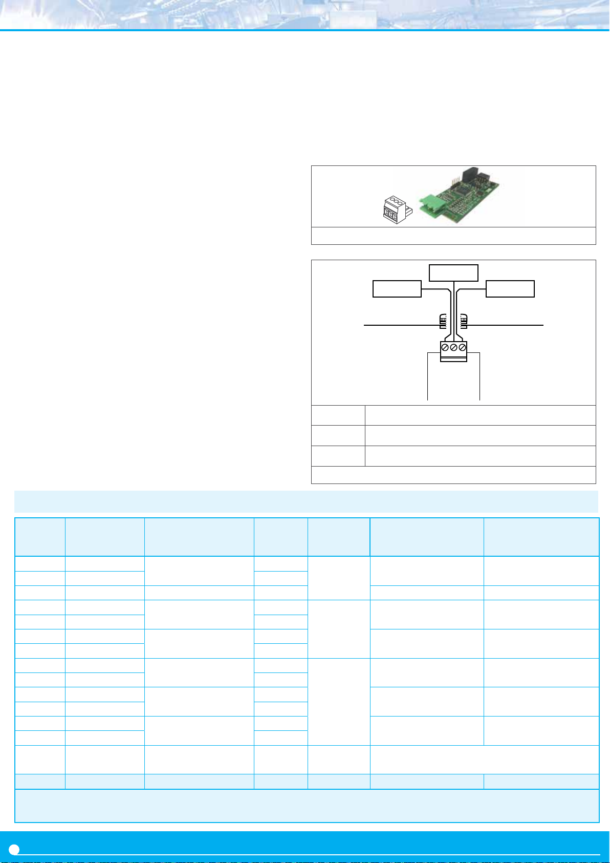
3. Opon
RTU
The RTU modules provide 1 port for communicaons
in Modbus RTU protocol. Use funcon ‘4’ (‘Read Input
Registers’) of the Modbus RTU protocol, to access the
instrument registers (reading value, alarm status,
memory of maximum and minimum, setpoint values, ...).
Opon RTU
Type of output Modbus RTU communicaon
Funcon implemented 4 (Read_Input_Registers)
Addresses 01 to 247
Excepon codes see secon 3.3
Registers* see secon 3.1
*available registers can vary for dierent instruments
Bus RS-485
Speed 57.6 Kbps to 600 bps
Data format 8e1 (standard), 8o1, 8n2
Bus terminator not included
Isolaon 1000 Vdc
Temperature operaon from 0 to 50 ºC
storage from -20 to +70 ºC
The communicaon parameters are congured from the
opons menu entry (‘Opt.1’, ‘Opt.2’ or ‘Opt.3’) of the
instrument.
The RTU modules are isolated between them and
between all other circuits of the instrument.
Figure 12 - Detail for the ‘RTU’ module
A wire
GNDB wire
GAB
Module RTU
Factory conguraon ‘Address 1’
‘Speed 19.2 Kbps’
‘Format 8e1’
‘Decimal point Auto’
Installaon allowed at slot 1, slot 2, slot 3
A Bus signal A
B Bus signal B
G GND
Figure 13 - Connecons for Modbus ‘RTU’ module
3.1 Registers accessible through Modbus RTU
Register Name Descripon Size Refresh 6 Digit Models
(LDB-26 y LDB-46)
0 DISPLAY1_L
1 DISPLAY1_H 16 bits
2 DECIMALES1 Decimals on display 16 bits 0 to 6
3 MAXMEM_L
4 MAXMEM_H 16 bits
5 MINMEM_L
6 MINMEM_H 16 bits
7 SETPOINT1_L
8 SETPOINT1_H 16 bits
9 SETPOINT2_L
10 SETPOINT2_H 16 bits
11 SETPOINT3_L
12 SETPOINT3_H 16 bits
13 STATUS
14 a 16 Reserved Reserved 16 x 3 bits Not accessible
Display value
Memory of maximum
Memory of minimum
Setpoint 1 value
Setpoint 2 value
Setpoint 3 value
Alarm status
Instrument status
16 bits
16 bits
16 bits
16 bits
16 bits
16 bits
16 bits
same
as display
every
30 seconds
every
2 seconds
same
as display
999999 to -199999 9999 to -1999
999999 to -199999 9999 to -1999
999999 to -199999 9999 to -1999
999999 to -199999 9999 to -1999
999999 to -199999 9999 to -1999
999999 to -199999 9999 to -1999*
bit 0...7 alarm status
bit 8...16 instrument status
4 Digit Models
(LDB-24 y LDB-44)
0 to 4
Not accessible
Table 1 - Registers accessible through MODBUS-RTU. Registers codied as binary numbers. Negave values codied in two’s complement. Available
registers can vary for dierent instruments. Register 11 is not accessible for instruments with formats LDB-24 and LDB-44 ( slot 3 is not available).
8
Page 38
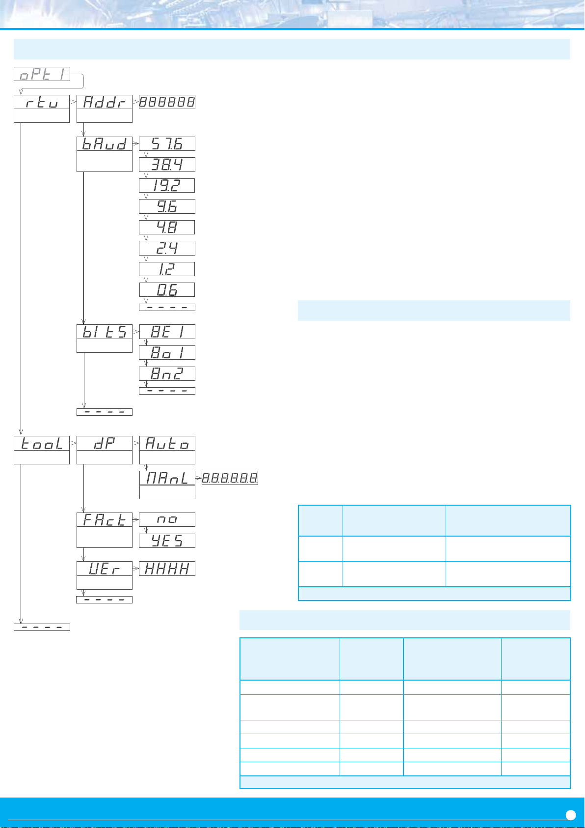
3.2 Conguraon menu
AddressConguraon
Speed
(kbps)
1 to 247
57.6 Kbps
...
...
to 600 bps
At the ‘Conguraon’ (‘rtu’) menu, congure the ‘Address’
(‘Addr’) parameter with the address value between ‘1’ and
‘247’, at the ‘Speed’ (‘bAud’) parameter select the bus speed
(in Kbps) and at the ‘Format’ (‘bItS’) parameters select the
data format.
Inside the ‘Tools’ (‘TooL’) menu, special tools and funcons
are grouped.
• the ‘Decimal point’ (‘dP’) menu is provided for
compability with ancient hardware that does not
support decimal point retransmission. By default, select
‘Automac’ (‘Auto’). If your instrument does nos transmit the
decimal point posion, select ‘Manual’ (‘MAnL’) and x
the posion of the decimal point manually.
• at the ‘Factory reset’ (‘FAct’) menu, select ‘yes’ to load the
default factory conguraon for the instrument.
the ‘Version’ (‘VEr’) menu informs of the current rmware
version installed in the module.
3.3 Excepon codes
Tools
Format
Factory
conguraon
Version
AutomacDecimal point
Manual
8 bits, even parity, 1 stop
8 bits, odd parity, 1 stop
8 bits, no parity, 2 stop
Move with LE
The Modbus RTU protocol denes the following scenarios
when a ‘Master’ is sending a frame to a ‘Slave’:
• the ‘Slave’ device receives the frame correctly and replies
with the requested data
• the ‘Slave’ devices detects a CRC error, parity error, or other.
and discards the frame without generang a reply frame. The
‘Master’ will detect a ‘TIMEOUT’ condion due to the absence
of reply.
• the ‘Slave’ device receives the frame correctly, but replies
with an ‘EXCEPTION_CODE’ as it can not process the funcon
or register requested.
The ‘EXCEPTION_CODES’ congured in the RTU module are :
Excep-
on code
0 ILLEGAL_FUNCTION
1
Table 2 - Excepon codes
Name Descripon
Requested funcon is not
supported
ILLEGAL_DATA_AD-
DRESS
Requested register is not
supported
3.4 Compable versions
Formats
LDB-26, LDB-46
--- --- LDB24-P, LDB44-P 41.57
LDB26-P, LDB46-P 50.00 --- ---
--- --- LDB24-T, LDB44-T 44.05
--- --- LDB24-R, LDB44-R 45.05
LDB26-C1, LDB46-C1 27.08 LDB24-C1, LDB44-C1 47.07
LDB26-CR, LDB46-CR 28.02 LDB24-C1, LDB44-C1 48.05
Table 3 - Firmware versions compable with the indicated registers
Firmware
version
Formats
LDB-24, LDB-44
Firmware
version
9
Page 39

3.5 Descripon and example of registers
Registers R0 and R1 (DISPLAY1_L y DISPLAY1_H)
Contains the display value of the instrument, codied in
two registers of 16 bits each. Possible values are from
999999 to -199999. Decimal point posion is codied at
register R2.
Example R0=FBF1 (hex) and R1=0009 (hex)
Register value = 0009 FBF1 (hex)
Reading value = 654321
Register R2 (DECIMALS1)
Contains the number of decimals of the display, codied
in a single register of 16 bits. Possible values are from
0 to 6.
Example R2=0002 (hex)
Number of decimals = 2 = 6543.21
Register R3 and R4 (MAXMEM_L and MAXMEM_H)
Contains the memory of maximum reading of the
instrument, codied in two registers of 16 bits each.
Possible values are from 999999 to -199999. Decimal
point posion is codied on register R2.
Example - same example as in R0 and R1 but accessing
to R3 and R4.
Registers R5 and R6 (MINMEM_L and MINMEM_H)
Contains the memory of minimum reading of the
instrument, codied in two registers of 16 bits each.
Possible values are from 999999 to -199999. Decimal
point posion is codied on register R2.
Example - same example as in R0 and R1 but accessing
to R5 and R6.
Registers R9 and R10 (SETPOINT2_L and SETPOINT2_H)
Contains the setpoint value of alarm 2, codied in two
registers of 16 bits each. Possible values are from 999999
to -199999. Decimal point posion is codied on register
R2.
Example - same example as in R0 and R1 but accessing
to R9 and R10.
Registers R11 and R12 (SETPOINT3_L and SETPOINT3_H)
Contains the setpoint value of alarm 3, codied in two
registers of 16 bits each. Possible values are from 999999
to -199999. Decimal point posion is codied on register
R2.
Example - same example as in R0 and R1 but accessing
to R11 and R12.
Register R13 (STATUS)
Informaon bit-by-bit, for the alarm status (on / o) and
instrument status. See below for a descripon.
Bit 0 Alarm 1 status (0 = inacve, 1 = acve)
Bit 1 Alarm 2 status (0 = inacve, 1 = acve)
Bit 2 Alarm 3 status (0 = inacve, 1 = acve)
Bit
3 to 7
Reserved
Bit 8 Display overrange
Bit 9 Display underrange
Bit 10 Lost communicaon with the main processor
Bit 11 to 15 Reserved
Registers R14, R15 and R16
Reserved
Registers R7 and R8 (SETPOINT1_L and SETPOINT1_H)
Contains the setpoint value of alarm 1, codied in two
registers of 16 bits each. Possible values are from 999999
to -199999. Decimal point posion is codied on register
R2.
Example - same example as in R0 and R1 but accessing
to R7 and R8.
10
Page 40
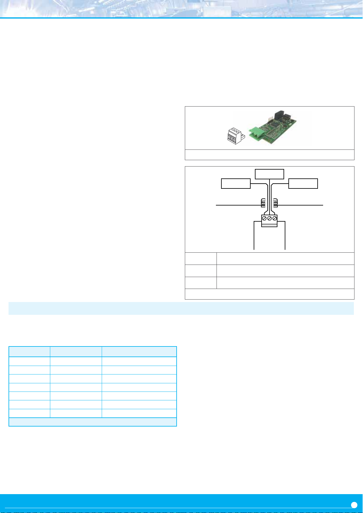
4. Opon
S4
The S4 modules provide 1 port for communicaons RS485
ASCII protocol. Protocol with ‘master’ - ‘slave’ architecture,
addressable up to 31 modules. Frames codied in representable ASCII characters (codes 32 to 255), which are visible
using ‘hyperterminal’ or similar programs. Instrument
Opon S4
Type of output RS-485 ASCII communicaon
Bus RS-485
Speed 57.6 Kbps to 600 bps
Data format 8n1 (standard), 8o1, 8n2, 8e1
Bus terminator not included
Protocol ASCII
Architecture ‘master - slave’
Addresses 01 to 31
‘Broadcast’ address 128
Registers* see secon 4.1
*available registers can vary for dierent instruments
Isolaon 1000 Vdc
Temperature operaon from 0 to 50 ºC
storage from -20 to +70 ºC
Factory conguraon ‘Mode Slave’
‘Address 1’
‘Speed 19.2 Kbps’
‘Format 8n1’
‘Decimal point Auto’
Conguraon ‘Master’ ‘Desnaon address 31’
‘Frequency 0.5 sec.’
Tools ‘Decimal point Auto’
‘Legacy O’
‘Answer delay 0 mSec.’
Installaon allowed at ‘Opt.1’, ‘Opt.2’, ‘Opt.3’
registers are accessible through the RS-485 ASCII port
(reading value, alarm status, memory of maximum and
minimum, setpoint values, ...). The communicaon
parameters are congured from the opons menu
entry (‘Opt.1’, ‘Opt.2’ or ‘Opt.3’) of the instrument. The S4
modules are isolated between them and between all other
circuits of the instrument.
Figure 14 - Detail for the ‘S4’ module
A wire
B wire
GAB
Module S4
A Bus signal A
B Bus signal B
G GND
Figure 15 - Connecons for ‘S4’ module
GND
4.1 Accessible registers
Display values (DISPLAY1, MAXMEM, MINMEM, AL1, AL2,
AL3) are codied with a minimum of 6 digits (le zeros
are added if necessary), polarity and decimal point.
Register Name Descripon
0 DISPLAY1 Display1 value
1 MAXMEM Memory of maximum
2 MINMEM Memory of minimum
3 AL1 Setpoint 1 value
4 AL2 Setpoint 2 value
5 AL3 Setpoint 3 value
6 STATUS Alarm status
Table 4 - Accessible registers for ASCII protocol.
Register 0 - DISPLAY1
Contains the display value of the instrument, in ASCII code,
including polarity (posive / negave) and decimal point.
Example 1 - R0=’+’ ‘0’ ’6’ ‘5’ ‘4’ ‘3’ ‘.’ ‘2’ Display value = 6543.2
Example 2 - R0=’-’ ‘0’ ‘0’ ‘0’ ‘4’ ‘.’ ‘5’ ‘2’ Display value = -4.52
Register 1 - MAXMEM
Contains the value for memory of maximum, in ASCII code,
including polarity (posive / negave) and decimal point.
Register 2 - MINMEM
Contains the value for memory of minimum, in ASCII code,
including polarity (posive / negave) and decimal point.
Register 3 - AL1
Contains the value for alarm 1 setpoint, in ASCII code,
including polarity (posive / negave) and decimal point.
Register 4 - AL2
Contains the value for alarm 2 setpoint, in ASCII code,
including polarity (posive / negave) and decimal point.
Register 5 - AL3
Contains the value for alarm 3 setpoint, in ASCII code,
including polarity (posive / negave) and decimal point.
Register 6 - STATUS
Contains the alarm status (on/o).
Bit 0 Alarm 1 status (0 = inacve, 1 = acve)
Bit 1 Alarm 2 status (0 = inacve, 1 = acve)
Bit 2 Alarm 3 status (0 = inacve, 1 = acve)
Bit 3 to 15 Reserved
11
Page 41
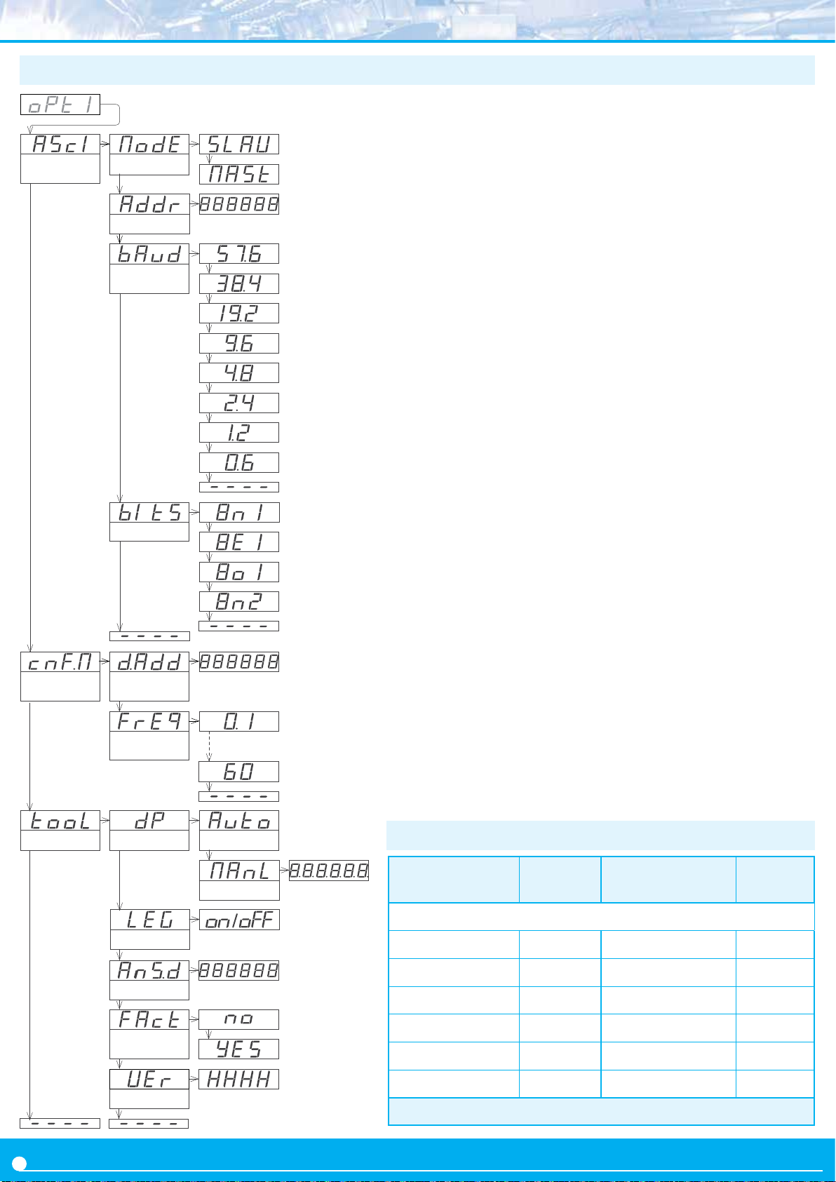
4.2 Conguraon menu
Conguraon
ASCII
Conguraon
‘Master’
Mode
Address
Speed
(kbps)
Format
Desnaon
address
Frequency
1 a 31
1 to 31
128 for ‘broadcast’
Mode ‘Slave’
Mode ‘Master’
0.1 seconds
0.5 seconds
1 seconds
5 seconds
15 seconds
60 seconds
At the ‘Conguraon ASCII’ (‘AScI’) menu, congure
the ‘Mode’ (‘ModE’) parameter to select the ‘slave’ or
the ‘master’ mode, at the ‘Address’ (‘Addr’) parameter
congure the local port address between ‘1’ and ‘31’, at
the ‘Speed’ (‘bAud’) parameter select the bus speed (in
Kbps) and at the ‘Format’ (‘bItS’) parameter select the data
format.
When working as ‘master’, the instrument connuously
transmits the display value data frame. The local module
address is ‘0’. Congure at menu ‘Conguraon Master’
(‘cnF.M’) the ‘Desnaon address’ (‘d.Add’) parameter
from ‘1’ to ‘31’ or use value ‘128’ for a broadcast message.
At parameter ‘Frequency’ (‘FrEq’) select the how oen the
frame with the reading value will be transmied.
Special tools are grouped inside the ‘Tools’ (‘TooL’) menu.
• the ‘Decimal point’ (‘dP’) menu is provided for
compability with ancient hardware that does not
support decimal point retransmission. By default,
select ‘Automac’ (‘Auto’). If your instrument does nos
transmit the decimal point posion, select
‘Manual’ (‘MAnL’) and x the posion of the decimal point
manually.
• the ‘Legacy mode’ (‘LEG’) parameter is provided to
maintain compability with instruments with older
communicaon protocols. Select ‘on’ to acvate this
mode.
• the ‘Answer delay’ (‘AnS.d’) parameter applies only
to ‘Slave’ mode. The local module delays the answer
frame. Congure for applicaons where the ‘Master’
needs addional me to switch between ‘transmit’ and
‘receive’ modes. Enter a numeric value between ‘0’ and
‘1000’ mSeconds.
• at the ‘Factory reset’ (‘FAct’) menu, select ‘yes’ to load
the default factory conguraon for the instrument.
the ‘Version’ (‘VEr’) menu informs of the current
rmware version installed in the module.
12
Tools
Decimal point
Legacy mode
Answer delay
Factory
conguraon
Version
Automac
Manual
use key ‘LE’ to
select
delay for answers, from 0
to 1000 mSec.
4.3 Compable versions
Formats
LDB-26, LDB-46
Instruments with access to registers 0, 1, 2, 6
LDB26-P, LDB46-P
LDB26-C1, LDB46-C1
LDB26-CR, LDB46-CR
Table 5 - Firmware versions compable with the indicated registers
Version
rmware
50.00
27.08
28.02
Formats
LDB-24, LDB-44
LDB24-P, LDB44-P
---
LDB24-T, LDB44-T
LDB24-R, LDB44-R
LDB24-C1, LDB44-C1
LDB24-CR, LDB44-CR
Version
rmware
41.57
44.05
45.05
47.07
48.05
---
Page 42
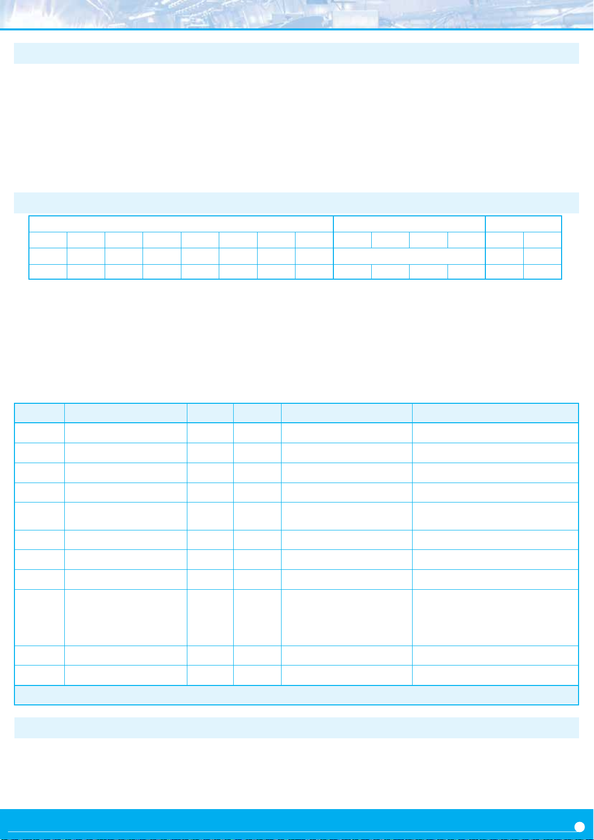
4.4 Frame types
The ASCII protocol denes the following frames:
• Frame ‘read’ (‘RD’). Id code 36. Request data frame. The
requested register is indicated into the ‘REG’ byte (‘Header’
secon).
• Frame ‘answer’ (‘ANS’). Id code 37. Response frame to a
request data frame. The requested register is indicated
into the ‘REG’ byte’ (‘Header’ secon). Data of the request
ed register is indicated into data bytes ‘D0’ to ‘Dn’ (‘Data’
secon).
• Frame ‘error’ (‘ERR’). Id code 38. Response frame to a
request data frame. Indicates that an error has occurred.
Error code is codied into the ‘REG’ byte (‘Header’ secon).
• Frame ‘ping’ (‘PING’). Id code 32. Used to conrm the
existence of the remote instrument.
-
• Frame ‘pong’ (‘PONG’). Id code 33. Response to a ‘ping’
frame. It conrms the existence of the remote instrument.
4.5 Frame structure
Header Data Trail
STX ID RSV FROM TO REG RSV LONG D0 D1 ... Dn CRC ETX
2 x 32 x x x 32 n+1 [data] x 3
0 1 2 3 4 5 6 7 8 9 ... n+7 n+8 n+9
Protocol frames have a structure made of ‘Header’, ‘Data’ and ‘Trail’.
Secon ‘Header’
Contains the start byte (‘STX’), the frame idener (‘ID’), the
origin address (‘FROM’) and the desnaon address (‘TO’),
the register id (‘REG’) and the length (‘LONG’) of the ‘Data’
secon.
Secon ‘Data’
Contains data for the requested register (‘REG’).
Secon ‘Trail’
Contains the ‘CRC’ code and the end of frame byte (‘ETX’).
‘Real value’ and ‘Frame value’
To use representable ASCII values, the real values are codied
before being sent into the frame. The following denions apply :
• ‘real value’ is the value of the eld without codicaon
• ‘frame value’ is the value of the eld, codied
Field Descripon Size Posion Real value Frame value
STX Start of frame 1 byte 0 does not apply 2
ID Frame type 1 byte 1 (see secon 4.4) real_value
RSV Reserved 1 byte 2 0 32
FROM Origin address 1 byte 3 0 (‘Master’) / 1 to 31 (‘Slave’) 32 + real_value
TO Desnaon address 1 byte 4 0 (‘Master’) / 1 to 31 (‘Slave’)
128 (‘broadcast’)
REG Register idencaon 1 byte 5 (see secon 4.1) 32 + real_value
RSV Reserved 1 byte 6 0 32
LONG Length of ‘Data’ secon 1 byte 7 n (between 0 and 32) 32 + real_value
D0 … Dn Data n bytes 8 to n+7 number 0 to 9
decimal point
polarity (+/-)
CRC CRC calculaon 1 byte n+8 does not apply (see secon 4.7)
ETX End of frame 1 byte n+9 does not apply 3
Table 6 - Descripon of the bytes for the ASCII frame
32 + real_value
ASCII code of the number (48 to 57)
ASCII code of decimal point (46)
ASCII code of ‘+’ (43)
ASCII code of ‘-’ (45)
4.6 Error codes
Frames ‘ERR’ contain within the ‘REG’ eld, the error code.
Available error codes are :
error 1 unknown register
error 2 display overrange
error 3 display underrange
error 4 CRC error
error 5 internal error
13
Page 43
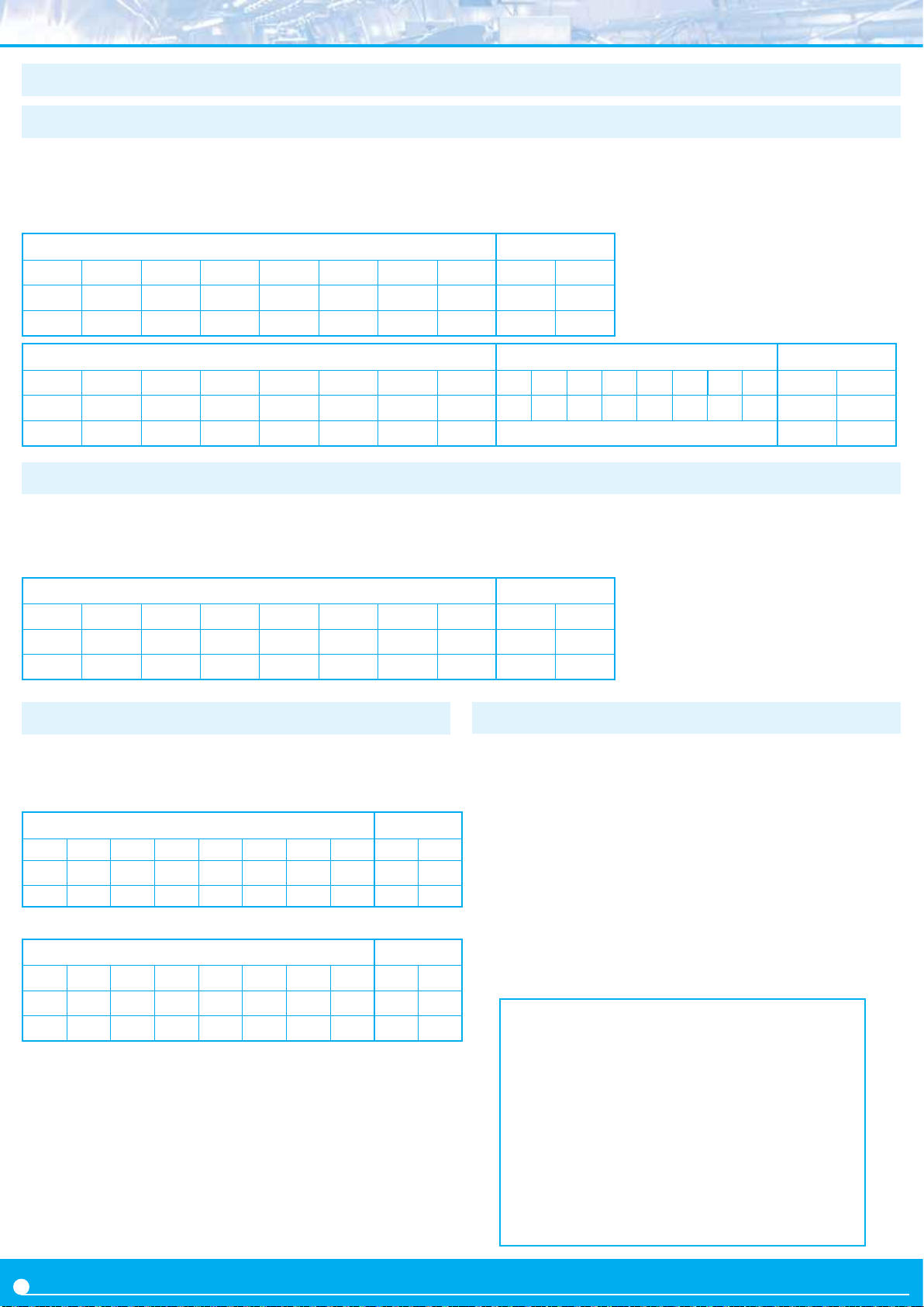
4.8 Frame examples
4.8.1 Frames ‘RD’ (36) and ‘ANS’ (37)
Example - ‘Master’ (address ‘0’) requests the value of register
‘0’ (display value) to the ‘Slave’ at address ‘28’ (‘RD’ frame)
and the ‘Slave’ replies to the ‘Master’ with a reply frame (‘ANS’
frame) containing the requested data (765.43).
*Instruments with 4 digits also send reading values formaed
with 6 digits : value -321.5 is transmied as -00321.5
Header Trail
STX ID RSV FROM TO REG RSV LONG CRC ETX
2 36 32 32 60 32 32 32 58 3
Start RD --- 0 28 0 --- 0 CRC Stop
Header Data Trail
STX ID RSV FROM TO REG RSV LONG D0 D1 D2 D3 D4 D5 D6 D7 CRC ETX
2 37 32 60 32 32 32 40 43 48 55 54 53 46 52 51 15 3
Start ANS --- 28 0 0 --- 8 +0765.43 CRC Stop
4.8.2 Frames ‘ERR’ (38)
Example - ‘Slave’ at address ‘11’ replies to the ‘Master’
(address ‘0’) with an error frame (‘ERR’ frame)
indicang that the requested register number is unknown
Header Trail
STX ID RSV FROM TO REG RSV LONG CRC ETX
2 38 32 43 32 33 32 32 46 3
Start ERR --- 11 0 1 --- 0 CRC Stop
(‘UNKNOWN_REGISTER’, error code ‘1’). The error code
is codied into the ‘REG’ byte. For a list of error code see
secon 4.6.
4.7.1 Frames ‘PING’ (32) and ‘PONG’ (33)
Example - ‘Master’ (address ‘0’) requests conrmaon of
existence to the ‘Slave’ at addrress ‘22’ (‘PING’ frame) and
the ‘Slave’ replies to the ‘Master’ with a ‘PONG’ frame.
Header Trail
STX ID RSV
2 32 32 32 54 32 32 32 52 3
Start Ping --- 0 22 0 --- 0 CRC Stop
Header Trail
STX ID RSV
2 33 32 54 32 32 32 32 53 3
Start
Pong
FROM
TO REG RSV
FROM
TO REG RSV
--- 22 0 0 --- 0 CRC Stop
LONG
LONG
CRC ETX
CRC ETX
4.7 CRC calculaon
The ‘frame value’ for the CRC byte is calculated applying a
XOR funcon to the ‘frame value’ (see secon 4.5) of all bytes
in secons ‘Header’ and ‘Data’, from byte ‘0’ (‘STX’) to the last
data byte (‘Dn’).
• if the calculated CRC value is lower than ‘32’, it is normalized
by applying the ‘one’s complement’ funcon .
CRC0=STX ^ ID ^ RSV ^ FROM ^ TO ^ REG ^ RSV ^ LONG ^ D0
^...^ Dn
• if (CRC0<32) -> CRC=!CRC0 (one’s complement funcon)
• if (CRC0>31) -> CRC=CRC0
//example of CRC calculaon in C language
int8 Calculate_CRC(int8 CRC_Posion)
{
int8 i,CRC=0;
for(i=0;c<CRC_Posion;c++)
{
crc=crc ^ frame[i];
}
if(crc<32) CRC=~CRC;
return(CRC);
}
14
Page 44
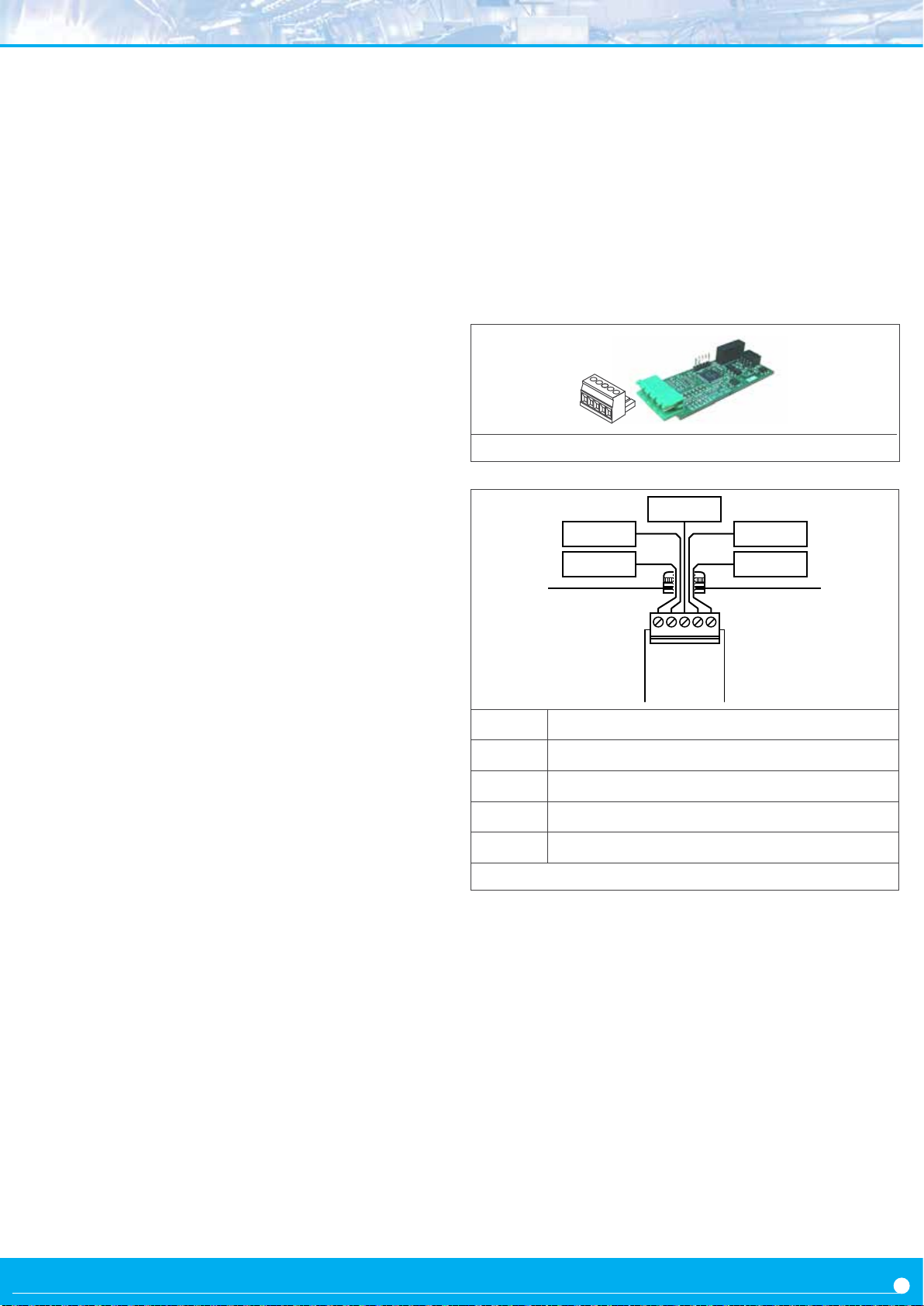
5. Opon
S2
The S2 modules provide 1 port for communicaons
RS232 ASCII protocol. The S2 modules use the same
protocol as the S4 modules (see secon 4), the only
dierence is the physical layer of the bus, that is RS232
for the S2.
S2 modules allow for point-to-point communicaon over
RS232 and also allow for mulnode communicaon over
Opon S2
Type of output RS-232 ASCII communicaon
Bus RS-232
Speed 57.6 Kbps a 600 bps
Data format 8n1 (standard), 8o1, 8n2, 8e1
Protocol ASCII
Architecture ‘master - slave’
Address 01 to 31
‘Broadcast’ address 128
Registers* see secon for S4 module
RS232 using a ‘Daisy-Chain’ type of connecon.
Terminals RX1 and TX1 are for the main communicaon
with the RS232 bus. Terminals RX2 and TX2 are for the
mulnode connecon, so all frames received at RX1 with
desnaon address dierent from the local address, will
be retransmied through TX2. On the same way, frames
received at RX2 with desnaon address dierent from
the local address, will be retransmied through TX1.
Figure 16 - Detail for the ‘S2’ module
Tx1
Rx1Rx2
Tx2
GND
*available registers can vary for dierent instruments
Isolaon 1000 Vdc
Temperature operaon from 0 to 50 ºC
storage from -20 to +70 ºC
Installaon allowed at ‘Opt.1’, ‘Opt.2’, ‘Opt.3’
D
CBA
E
Module S2
A GND
B
C
D
E
Figure 17 - Connecons for ‘S2’ module
Rx data recepon
Tx data transmission
‘Daisy chain’ Rx data recepon
‘Daisy chain’ Tx data transmission
15
Page 45
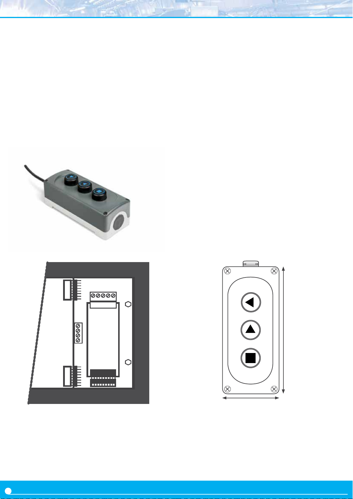
1. Remote keypad LDB-RKB
Industrial keypad with 3 push buons to connect to large format meters from LDB series. It allows to replicate the front
keypad of the instrument to a remote locaon.
A RKB remote keypad allows the operator to access the
advanced control funcons from the large format
meters, such as fast access to alarm setpoints, preset value
modicaon, access to maximum and minimum reading
values, signal tare for load applicaons, front reset, manual
alarm unlock, ...
All these features are accessible while maintaining the main
feature of these instruments, which is the installaon in
heights for long distance reading.
The RKB remote keypad is provided with an industrial IP65
protected housing, with cable gland output, aligned with the
technical specicaons of the LDB series. The RKB remote
keypad can be easily installed against wall. The push buons
are 25 mm size for easy use even with protecon gloves.
The RKB remote keypad is provided with labeled push
buons and does not included cable.
Normal buon state open
Recommended wire 0.25 mm2
Protecon IP65
Output by cable gland
Mounng accepts wall mount
Color grey
Material plasc
Weight 200 gr
GND
(<)
SQ
UP
(5)
LE
(3)
Connect the wire to the 4 pole terminal located close to the
input signal module. Connect 4 wires for keys ‘SQ’ (<), ‘UP’
(5), ‘LE’ (3) and common. Pass the wires through the cable
gland idened as ‘remote keypad’ (see Figure 2) and connect
the other end to the internal RKB push buons.
181 mm
75 mm
2
Page 46
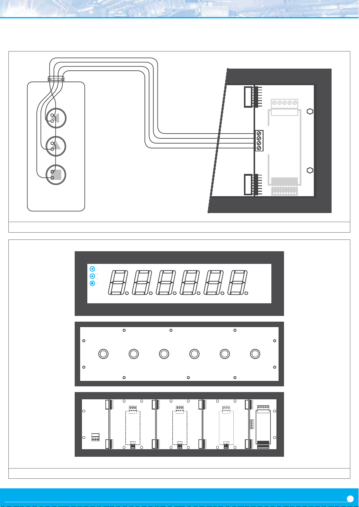
Figure 1 - Connecons from RKB to the internal 4 pole terminal
GND
SQ
UP
(5)
LE
(<)
(3)
Power
Remote keypad
Opon 3 Opon 2
Figure 2 - LDB-26 instrument front view (top), rear view (middle) and internal view (boom).
SignalOpon 1
3
Page 47

WARRANTY/DISCLAIMER
OMEGA ENGINEERING, INC. warrants this unit to be free of defects in materials and workmanship for a
period of 61 months from date of purchase. OMEGA’s WARRANTY adds an additional one (1) month grace
period to the normal five (5) year product warranty to cover handling and shipping time. This ensures
that OMEGA’s customers receive maximum coverage on each product.
If the unit malfunctions, it must be returned to the factory for evaluation. OMEGA’s Customer Service
Department will issue an Authorized Return (AR) number immediately upon phone or written request.
Upon examination by OMEGA, if the unit is found to be defective, it will be repaired or replaced at no
charge. OMEGA’s WARRANTY does not apply to defects resulting from any action of the purchaser,
including but not limited to mishandling, improper interfacing, operation outside of design limits,
improper repair, or unauthorized modification. This WARRANTY is VOID if the unit shows evidence of
having been tampered with or shows evidence of having been damaged as a result of excessive corrosion;
or current, heat, moisture or vibration; improper specification; misapplication; misuse or other operating
conditions outside of OMEGA’s control. Components in which wear is not warranted, include but are not
limited to contact points, fuses, and triacs.
OMEGA is pleased to offer suggestions on the use of its various products. However,
OMEGA neither assumes responsibility for any omissions or errors nor assumes liability for
any damages that result from the use of its products in accordance with information provided
by OMEGA, either verbal or written. OMEGA warrants only that the parts manufactured by the
company will be as specified and free of defects. OMEGA MAKES NO OTHER WARRANTIES OR
REPRESENTATIONS OF ANY KIND WHATSOEVER, EXPRESSED OR IMPLIED, EXCEPT THAT OF
TITLE, AND ALL IMPLIED WARRANTIES INCLUDING ANY WARRANTY OF MERCHANTABILITY
AND FITNESS FOR A PARTICULAR PURPOSE ARE HEREBY DISCLAIMED. LIMITATION OF
LIABILITY: The remedies of purchaser set forth herein are exclusive, and the total liability of
OMEGA with respect to this order, whether based on contract, warranty, negligence,
indemnification, strict liability or otherwise, shall not exceed the purchase price of the
component upon which liability is based. In no event shall OMEGA be liable for
consequential, incidental or special damages.
CONDITIONS: Equipment sold by OMEGA is not intended to be used, nor shall it be used: (1) as a “Basic
Component” under 10 CFR 21 (NRC), used in or with any nuclear installation or activity; or (2) in medical
applications or used on humans. Should any Product(s) be used in or with any nuclear installation or
activity, medical application, used on humans, or misused in any way, OMEGA assumes no responsibility
as set forth in our basic WARRANTY/DISCLAIMER language, and, additionally, purchaser will indemnify
OMEGA and hold OMEGA harmless from any liability or damage whatsoever arising out of the use of the
Product(s) in such a manner.
RETURN REQUESTS/INQUIRIES
Direct all warranty and repair requests/inquiries to the OMEGA Customer Service Department. BEFORE
RETURNING ANY PRODUCT(S) TO OMEGA, PURCHASER MUST OBTAIN AN AUTHORIZED RETURN (AR)
NUMBER FROM OMEGA’S CUSTOMER SERVICE DEPARTMENT (IN ORDER TO AVOID PROCESSING
DELAYS). The assigned AR number should then be marked on the outside of the return package and on any
correspondence.
The purchaser is responsible for shipping charges, freight, insurance and proper packaging to prevent
breakage in transit.
FOR WARRANTY RETURNS, please have the
following information available BEFORE contacting
OMEGA:
1. Purchase Order number under which the product
was PURCHASED,
2. Model and serial number of the product under
warranty, and
3. Repair instructions and/or specific problems
relative to the product.
OMEGA’s policy is to make running changes, not model changes, whenever an improvement is possible. This affords our
customers the latest in technology and engineering.
OMEGA is a trademark of OMEGA ENGINEERING, INC.
© Copyright 2018 OMEGA ENGINEERING, INC. All rights reserved. This document may not be copied, photocopied,
reproduced, translated, or reduced to any electronic medium or machine-readable form, in whole or in part, without the prior
written consent of OMEGA ENGINEERING, INC.
FOR NON-WARRANTY REPAIRS, consult
OMEGA for current repair charges. Have
the following information available BEFORE
contacting OMEGA:
1. Purchase Order number to cover the COST
of the repair,
2. Model and serial number of the product, and
3. Repair instructions and/or specific problems
relative to the product.
Page 48

Where Do I Find Everything I Need for
Process Measurement and Control?
OMEGA…Of Course!
Shop online at omega.com
TEMPERATURE
MU
Thermocouple, RTD & Thermistor Probes, Connectors,
Panels & Assemblies
MU
Wire: Thermocouple, RTD & Thermistor
MU
Calibrators & Ice Point References
MU
Recorders, Controllers & Process Monitors
MU
Infrared Pyrometers
PRESSURE, STRAIN AND FORCE
MU
Transducers & Strain Gages
MU
Load Cells & Pressure Gages
MU
Displacement Transducers
MU
Instrumentation & Accessories
FLOW/LEVEL
MU
Rotameters, Gas Mass Flowmeters & Flow Computers
MU
Air Velocity Indicators
MU
Turbine/Paddlewheel Systems
MU
Totalizers & Batch Controllers
pH/CONDUCTIVITY
MU
pH Electrodes, Testers & Accessories
MU
Benchtop/Laboratory Meters
MU
Controllers, Calibrators, Simulators & Pumps
MU
Industrial pH & Conductivity Equipment
DATA ACQUISITION
MU
Communications-Based Acquisition Systems
MU
Data Logging Systems
MU
Wireless Sensors, Transmitters, & Receivers
MU
Signal Conditioners
MU
Data Acquisition Software
HEATERS
MU
Heating Cable
MU
Cartridge & Strip Heaters
MU
Immersion & Band Heaters
MU
Flexible Heaters
MU
Laboratory Heaters
ENVIRONMENTAL
MONITORING AND CONTROL
MU
Metering & Control Instrumentation
MU
Refractometers
MU
Pumps & Tubing
MU
Air, Soil & Water Monitors
MU
Industrial Water & Wastewater Treatment
MU
pH, Conductivity & Dissolved Oxygen Instruments
M5680/0318
 Loading...