

Page 1
User’s Guide
Shop online at
omega.com
e-mail: [email protected]
For latest product manuals:
www.omegamanual.info
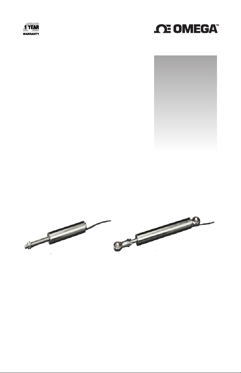
LD320, LD620, LD621, LD630, LD650 Series
DISPLACEMENT TRANSDUCERS
Page 2

omega.com [email protected]
Servicing North America:
U.S.A. Omega Engineering, Inc.
Headquarters: Toll-Free: 1-800-826-6342 (USA & Canada only)
Customer Service: 1-800-622-2378 (USA & Canada only)
Engineering Service: 1-800-872-9436 (USA & Canada only)
Tel: (203) 359-1660 Fax: (203) 359-7700
e-mail: [email protected]
For Other Locations Visit omega.com/worldwide
Index
Section Title
1.0 Introduction .
2.0 Installation
2.1 Mounting the Transducer .
2.2 Cores
2.3 Carriers
2.3.1 Guided Carriers
2.3.2 Ball Tips
2.3.3 Springs
2.3.4 Universal Joints
2.3.5 Thread Mount Option
3.0 Electrical Interfaces
3.1 Standard LVDT
3.2 4-20MA
3.3 DC Voltage
3.4 Digital
4.0 Conditioning
5.0 Marking
The information contained in this document is believed to be correct, but OMEGA accepts no liability for any errors it contains,
and reserves the right to alter specifications without notice.
Page 3
1.0: Introduction
Omega's new LD320, LD620, LD621, LD630 range of displacement transducers forms a wide range of transducers offering measurement ranges
from ±2.5 mm to ±150 mm. The LD320, LD620, LD621, LD630 offers the
advantage of a shorter body than traditional displacement transducers.
Furthermore, four electrical output types are provided; these are standard
LVDT, 4-20 mA, isolated DC voltage and digital outputs.
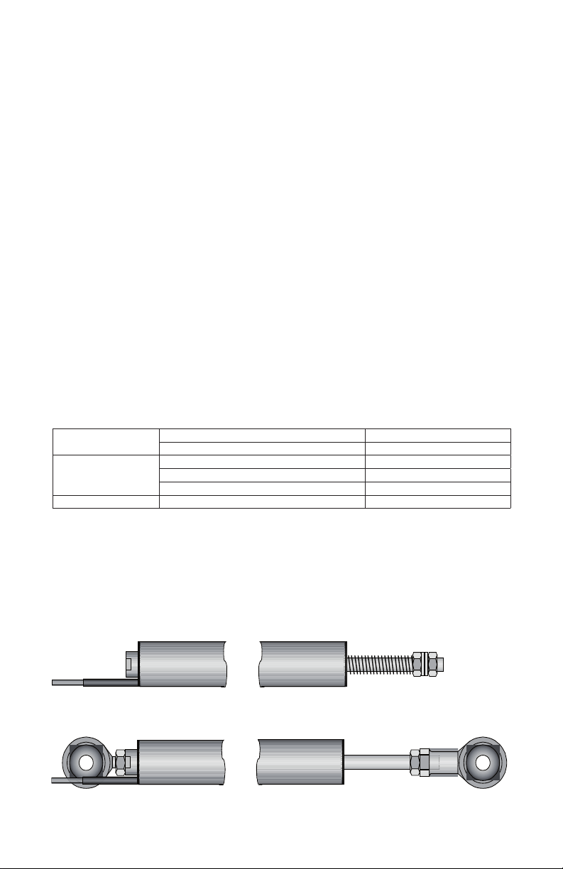
All models in the LD320, LD620, LD621, LD630 can be configured with
guided or unguided core for frictionless operation. The wide bore to core
clearance of the LD320, LD620, LD621, LD630 makes installation and
alignment a very easy process. The guided versions are provided with
polymer bearings for high rigidity and are available with special tips, universal joint fittings and return springs. The universal joints are useful in applications where lever movements induce variations in the motion straightness.
The rugged construction of the LD320, LD620, LD621, LD630 and the
options of IP65 and IP67 rating makes these transducers a cost-effective
product suitable for use in harsh environments.
GENERAL SPECIFICATION
Storage
Temperature
Operating
Temperature
Linearity 0.2% FSO
LVDT Variants -40 °C to +120 °C
4-20 mA, DC and Digital Variants -20 °C to +85 °C
LVDT Variants -40 °C to +120 °C
4-20 mA and DC Variants 0 °C to +65 °C
Digital variants (Transducer only) -40 °C to +120 C
For full specification please refer to the Product
Datasheet or catalog.
Typical Mechanical Configurations
Page 4
2.0: Installation
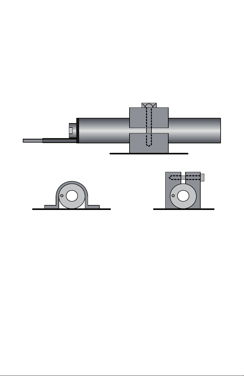
IF POSSIBLE, CENTRALISE LVDT
2.1: Mounting the Transducer
LVDT based transducers are a reliable and proven technology that is
well established in all areas of manufacturing and control industries.
The majority of the associated problems experienced with their application and use are totally avoidable, particularly if sufficient thought is
given during the initial design stages of equipment to the positioning and
clamping methods employed for these feedback elements.
LVDT’s, being of inductive nature, are susceptible to some degree to the
influence of magnetic fields.
The LD320, LD620, LD621, LD630, LD650, transducers contain an integral magnetic screen that reduces these effects. However, the transducer
should be positioned well away from electric motors, relays and permanent
magnets. If this is not possible checks should be made on the influence of
such items.
Clamping of the coil assembly should be carefully considered. Some
example methods are shown below. Ideally the body of the transducers
should be clamped centrally in a pinch or yoke type clamp, manufactured
from a low conductivity, non-magnetic material.
Irrespective of clamping method, care must be taken not to over-tighten
retaining screws as distortion of the body may prove damaging to the
integrity of the transducer and adversely affect the geometry of the installation.
If the LVDT is to be mounted on equipment subject to high ”g” then,
dependent on the direction of these forces, it may be advantageous to
consider end to end clamping in preference to over body clamping.
For Universal Joint fittings maximum tightening torque on the ball = 2.5
Nm.
Page 5

2.0: Installation (continued)
2.2: Cores
The standard core supplied is a ∅6.35 mm Core with M4 x 0.7 x 12 mm
female thread at both ends for mounting onto a carrier. The magnetic core
has been manufactured to achieve optimum performance and any subsequent handling of the core which results in stress being imparted will
render the calibration void. This includes over-tightening of the core during
installation onto its carrier. Hand tightening and retention by means
of a suitable thread locking anaerobic retainer
is the recommended procedure.
2.3: Carriers
A standard length carrier is available for each model of transducer, manufactured from 316 stainless steel and incorporating an M4 x 0.7 x 10 mm
long male thread for attachment to the standard core and an M6 x 1.0 x 17
mm male thread for attachment to the fixture.
2.3.1: Guided Carriers
Mounting: Normal mounting methods apply (see Installation). Careful consideration should be given to alignment; the carrier must be able to move
freely within the transducer core. Side force should be kept to a minimal
level.
Maintenance: Check for free movement of the carrier when in the vertical
plane. The polymer guide bearing is maintenance free.
2.3.2: Ball Tips
This option is for use with the Guided Carrier and
is attached via an adapter fitted to the threaded end of the core carrier.
Side forces that may exert undue pressure and flex the carrier must be
avoided.
2.3.3: Springs
A spring may be fitted externally in conjunction with a guided carrier and
also with a ball tip.
2.3.4: Universal Joints
Mounting: All LD320, LD620, LD621, LD630 transducers up to 300 mm
total measurement range (±150 mm) may be mounted in any axis; it is
recommended that the rear rod end bearing (near cable exit) is mounted
on the static component. (The larger transducers, because of the increase
in weight, may exhibit bowing of the carrier and therefore mounting in the
horizontal plane should either be avoided or additional support given to the
body. This option is used with the guided core.)
Maintenance: Periodic inspection of locking screws and nuts etc. is advisable depending upon the Customer’s application. Rod end bearings
should be able to move freely and have minimal side play.
Page 6
2.0: Installation (continued)
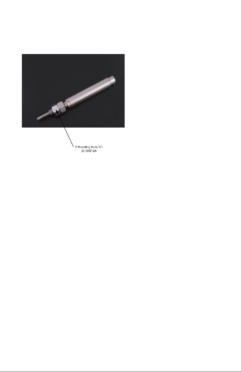
2.3.5: Thread Mount Option
- LD650 Series
Page 7
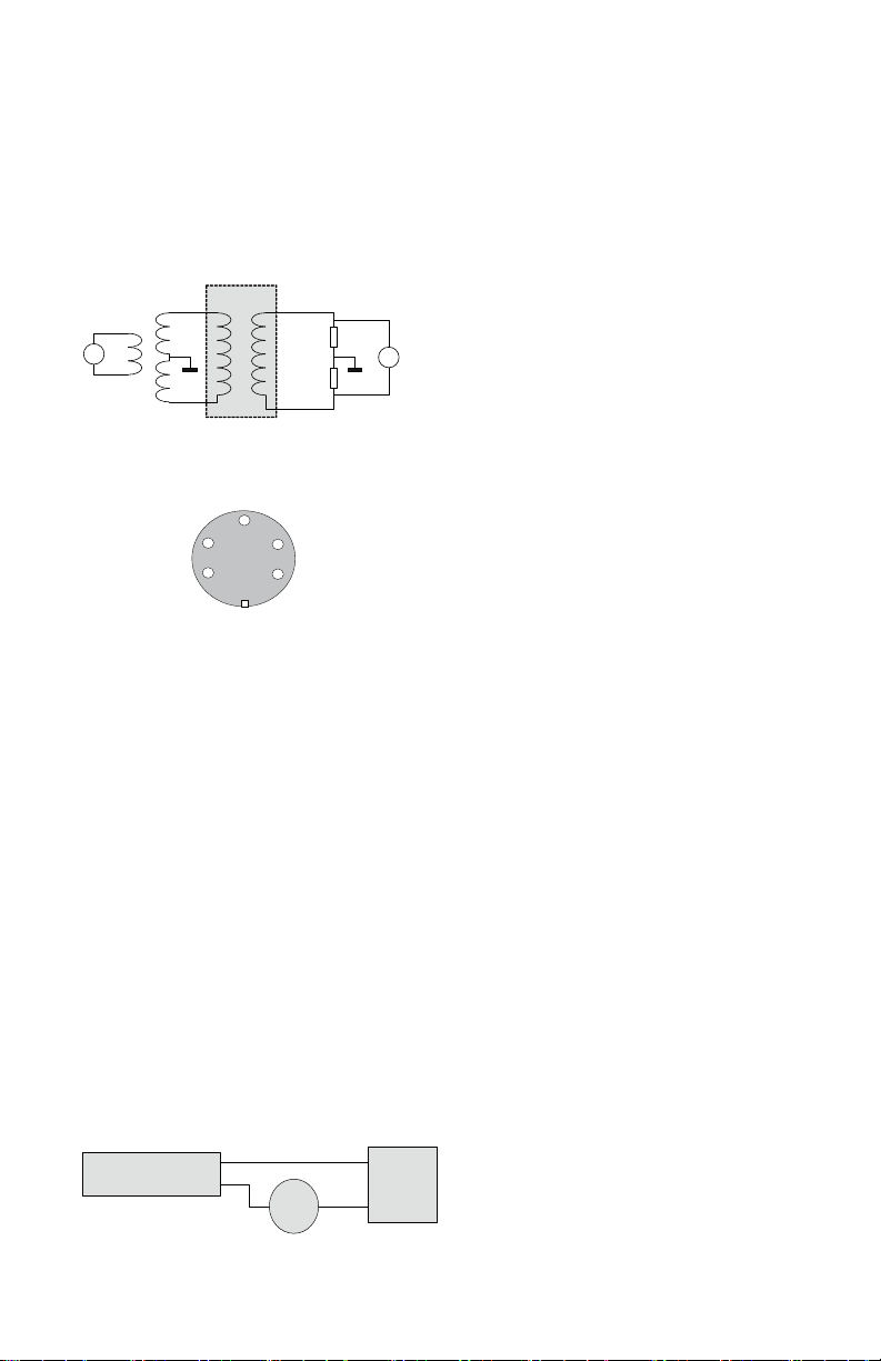
3.0: Electrical Interfaces
Primary Sec ondary
LVDT
Excitation
0V 0V50K
50K
Load Resist ance
Voltmeter AC
White
Green
Red
Blue
Screen to Case
Red
3
5
Plug view into pin s
4
1
2
BlueWhite
Green
S-Series
4-20 mA
Readout
-
+
+ Voltage
Power Supply
10 to 30 VDC
Red
Blue
3.1: Standard LVDT
The LD320, LVDT output transducer is designed to operate with an excitation voltage of 3 ± 1 V rms, an excitation frequency of 5 ± 0.5 kHz into
a 100 kΩ load as detailed below. Operation in different configurations
may mean the optimum performance is degraded.
Standard LVDT Connector 5 pin 240º DIN
The LD320 range of LVDT transducers operate on the principal that movement of a core inside the transducer body is detected by a differential
change in output on two secondary coils, the primary coil(s) being energized
by an appropriate AC excitation signal. With the core in a central position,
the coupling from the primary to each secondary is equal and opposite and
therefore cancel out, thus the resultant output voltage is zero. As the core
is displaced further into one secondary, its voltage increases proportionally
and the other secondary voltage decreases hence the output changes in
magnitude and phase in proportion to movement in either direction from null.
The red and white connections are in phase for inward movement (i.e.
towards the cable end).
The output signal depends on both core movement and energization voltage
and is expressed as a sensitivity in mV
output
/ V
energizing
/ mm travel.
3.2: 4-20 MA
The LD630 and LD650 are configured as a two wire 4-20 mA loop device,
the transducer provides a current between 4 mA (fully out) and 20 mA
(fully in). The transducer requires an excitation voltage between 10 VDC
and 30 VDC.
Note: 4-20 mA products are designed to operate with a maximum loop
resistance of 600 W.
Page 8
S-Series
Signal
Return
Return
+ Voltage
Power Supply
10 to 30 VDC
Voltage
Readout
Yellow
Green
Blue
Red
10 kΩ
3.0: Electrical Interfaces (continued)
S-Series
4-20 mA
Readout
-
+
+ Voltage
Power Supply
10 to 30 VDC
Red
Blue
S-Series
Signal
Return
Return
+ Voltage
Power Supply
10 to 30 VDC
Voltage
Readout
Yellow
Green
Blue
Red
10 kΩ
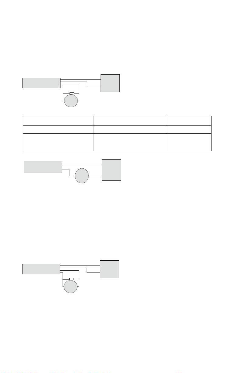
3.3: DC Voltage
The LD620 and LD621 can be configured to provide a DC voltage output
as shown below;
Measurement Range Output Output
0-d mm 0-10 VDC
-d/2 to +d/2 mm -5 VDC
to +5 VDC
The transducer requires an excitation voltage between 10 VDC and 30
VDC.
The transducer output is electrically isolated from the input supply.
Note: to achieve calibrated accuracy the load must be 10 kW between
Yellow and Green,
3.4: DIGITAL
Digital versions of the LD640 transducers are supplied with an integral
PIE module.
This module is fully compatible with LDN232. For details see Digital
Probe User Leaflet.
Page 9

4.0: Conditioning
The 4-20 mA and DC output version of the transducer require no signal
conditioning other than being connected to an appropriate receiver such
as a voltmeter, A/D converter or current meter.
LVDT transducers usually require the signal to be conditioned either by
end user amplifiers or with Omega conditioning circuits. Information on
these products can be obtained from original supplier.
5.0: Marking
Products with integrated electronics are CE marked.
Digital probes are CE marked.
Page 10

WARRANTY/DISCLAIMER
OMEGA ENGINEERING, INC. warrants this unit to be free of defects in materials and workmanship for
a period of 13 months from date of purchase. OMEGA’s WARRANTY adds an additional one (1) month
grace period to the normal one (1) year product warranty to cover handling and shipping time. This
ensures that OMEGA’s customers receive maximum coverage on each product.
If the unit malfunctions, it must be returned to the factory for evaluation. OMEGA’s Customer Service
Department will issue an Authorized Return (AR) number immediately upon phone or written request.
Upon examination by OMEGA, if the unit is found to be defective, it will be repaired or replaced at no
charge. OMEGA’s WARRANTY does not apply to defects resulting from any action of the purchaser,
including but not limited to mishandling, improper interfacing, operation outside of design limits,
improper repair, or unauthorized modification. This WARRANTY is VOID if the unit shows evidence
of having been tampered with or shows evidence of having been damaged as a result of excessive
corrosion; or current, heat, moisture or vibration; improper specification; misapplication; misuse or
other operating conditions outside of OMEGA’s control. Components in which wear is not warranted,
include but are not limited to contact points, fuses, and triacs.
OMEGA is pleased to offer suggestions on the use of its various products. However,
OMEGA neither assumes responsibility for any omissions or errors nor assumes liability for any
damages that result from the use of its products in accordance with information provided by OMEGA,
either verbal or written. OMEGA warrants only that the parts manufactured by the company will be as
specified and free of defects. OMEGA MAKES NO OTHER WARRANTIES OR REPRESENTATIONS
OF ANY KIND WHATSOEVER, EXPRESSED OR IMPLIED, EXCEPT THAT OF TITLE, AND ALL
IMPLIED WARRANTIES INCLUDING ANY WARRANTY OF MERCHANTABILITY AND FITNESS
FOR A PARTICULAR PURPOSE ARE HEREBY DISCLAIMED. LIMITATION OF LIABILITY: The
remedies of purchaser set forth herein are exclusive, and the total liability of OMEGA with respect to
this order, whether based on contract, warranty, negligence, indemnification, strict liability or otherwise,
shall not exceed the purchase price of the component upon which liability is based. In no event shall
OMEGA be liable for consequential, incidental or special damages.
CONDITIONS: Equipment sold by OMEGA is not intended to be used, nor shall it be used: (1) as
a “Basic Component” under 10 CFR 21 (NRC), used in or with any nuclear installation or activity; or
(2) in medical applications or used on humans. Should any Product(s) be used in or with any nuclear
installation or activity, medical application, used on humans, or misused in any way, OMEGA assumes
no responsibility as set forth in our basic WARRANTY / DISCLAIMER language, and, additionally,
purchaser will indemnify OMEGA and hold OMEGA harmless from any liability or damage whatsoever
arising out of the use of the Product(s) in such a manner.
Direct all warranty and repair requests/inquiries to the OMEGA Customer Service Department.
RETURN REQUESTS/INQUIRIES
BEFORE RETURNING ANY PRODUCT(S) TO OMEGA, PURCHASER MUST OBTAIN AN
AUTHORIZED RETURN (AR) NUMBER FROM OMEGA’S CUSTOMER SERVICE DEPARTMENT (IN
ORDER TO AVOID PROCESSING DELAYS). The assigned AR number should then be marked on the
outside of the return package and on any correspondence.
The purchaser is responsible for shipping charges, freight, insurance and proper packaging to prevent
breakage in transit.
FOR WARRANTY RETURNS, please have the
following information available BEFORE
contacting OMEGA:
1. Purchase Order number under which
the product was PURCHASED,
2. Model and serial number of the product under
warranty, and
3. Repair instructions and/or specific
problems relative to the product.
OMEGA’s policy is to make running changes, not model changes, whenever an improvement is possible.
This affords our customers the latest in technology and engineering.
OMEGA is a trademark of OMEGA ENGINEERING, INC.
© Copyright 2017 OMEGA ENGINEERING, INC. All rights reserved. This document may not be copied, photocopied, repro-
duced, translated, or reduced to any electronic medium or machine-readable form, in whole or in part, without the prior written
consent of OMEGA ENGINEERING, INC.
FOR NON-WARRANTY REPAIRS,
consult
OMEGA for current repair charges. Have the
following information available BEFORE
contacting OMEGA:
1. Purchase Order number to cover the
COST of the repair,
2. Model and serial number of the product, and
3. Repair instructions and/or specific problems
relative to the product.
Page 11

Where Do I Find Everything I Need for
Process Measurement and Control?
OMEGA…Of Course!
Shop online at omega.com
TEMPERATURE
MU
Thermocouple, RTD & Thermistor Probes, Connectors, Panels & Assemblies
MU
Wire: Thermocouple, RTD & Thermistor
MU
Calibrators & Ice Point References
MU
Recorders, Controllers & Process Monitors
MU
Infrared Pyrometers
PRESSURE, STRAIN AND FORCE
MU
Transducers & Strain Gages
MU
Load Cells & Pressure Gages
MU
Displacement Transducers
MU
Instrumentation & Accessories
FLOW/LEVEL
MU
Rotameters, Gas Mass Flowmeters & Flow Computers
MU
Air Velocity Indicators
MU
Turbine/Paddlewheel Systems
MU
Totalizers & Batch Controllers
pH/CONDUCTIVITY
MU
pH Electrodes, Testers & Accessories
MU
Benchtop/Laboratory Meters
MU
Controllers, Calibrators, Simulators & Pumps
MU
Industrial pH & Conductivity Equipment
DATA ACQUISITION
MU Communications-Based Acquisition Systems
MU Data Logging Systems
MU Wireless Sensors, Transmitters, & Receivers
MU Signal Conditioners
MU Data Acquisition Software
HEATERS
MU
Heating Cable
MU
Cartridge & Strip Heaters
MU
Immersion & Band Heaters
MU
Flexible Heaters
MU
Laboratory Heaters
ENVIRONMENTAL
MONITORING AND CONTROL
MU
Metering & Control Instrumentation
MU
Refractometers
MU
Pumps & Tubing
MU
Air, Soil & Water Monitors
MU
Industrial Water & Wastewater Treatment
MU
pH, Conductivity & Dissolved Oxygen Instruments
M4345/1217
 Loading...