

Page 1
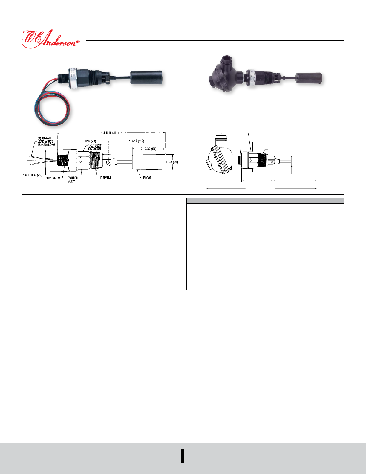
Model L8 FLOTECT® Liquid Level Switch
[28.58]
10.875 [276.23]
1/2 FEMALE NPT
CONDUIT CONNECTION
By Dwyer
Specications - Installation and Operating Instructions
Model L8 Model L8-WP
1-5/16 OCTAGON [33.34]
ø1-21/32
1/2 NPTM
[41.31]
3-1/16 [77.79]
1 NPTM
2-17/32
[64.29]
4-5/16 [109.54]
Bulletin E-41
ø1-1/8
Model L8 Flotect® Liquid Level Switch features a leak proof body and oat constructed
from tough, durable polyphenylene sulde (PPS) which has excellent chemical
resistance. Because the liquid level snap switch is magnetically actuated, there is
no direct mechanical linkage to leak or fail, assuring longer life and decreased
maintenance costs. This inexpensive unit is ideal for liquid level alarm, indication or
control. Installation is quick and easy — simply install in a horizontal position with the
index arrow pointing down.
The L8 Flotect
per UL standard 508, suitable for mounting in a protected environment. This lightweight
switch can be used in numerous chemical process, industrial systems and similar
applications where process conditions are compatible with polyphenylene sulde,
ceramic 8 and 316 stainless steel. This liquid level switch provides accurate setpoint
control of liquids with specic gravities as low as 0.6. This compact and reliable control
is designed to handle temperatures up to 212°F (100°C) and pressures to 150 psig
(10 bar).
MODEL
L8 Level Switch
OPTIONS
-MV, Gold Plated Contacts, for dry circuits. Rated 1A @ 125 VAC; 1A resistive, 0.5A
inductive @ 30 VDC. Example L8-MV
-INC, Inconel
parts are Inconel
-WP, Weatherproof Enclosure. Optional housing is phenylpolioxide and provides
weatherproof protection for electrical wiring. Example: L8-WP
INSTALLATION
1. The Model L8 Level Switch is designed for use in clean, compatible process media
free from scale, debris and other foreign material which could collect on the oat and
impede its movement. Build up from such materials will prevent proper operation. See
wetted materials list in the specications to assure compatibility with process liquids.
2. Unpack switch and remove any packing material from the switch and oat. Due
to variations in ttings and amount of thread engagement, oat must be checked for
proper operation during installation.
®
Liquid Level Control is UL recognized as an industrial motor controller
®
Option. Inconel® alloy replaces standard 316 SS wetted parts. Wetted
®
alloy, ceramic 8, and Polyphenylene Sulde. Example: L8-INC
SPECIFICATIONS
Service: Compatible liquids.
Wetted Materials: Float and Body: Polyphenylene Sulde (PPS); Pin and Spring:
316 SS or Inconel
Temperature Limit: 212°F (100°C).
Pressure Limit: 150 psig (10.34 bar).
Enclosure Rating: General purpose. WP option is weatherproof.
Switch Type: SPDT snap switch. MV option is a SPDT gold contact snap switch.
Electrical Rating: 5 A @ 125/250 VAC, 5 A resistive, 3 A inductive @ 30 VDC. MV
option: 0.1 A @ 125 VAC, 1 A resistive, 0.5 A inductive @ 30 VDC.
Electrical Connections: 18 AWG, 18˝ (460 mm) long.
Conduit Connection: 1/2˝ male NPT.
Process Connection: 1˝ male NPT.
Mounting Orientation: Horizontal with index arrow pointing down.
Weight: 5 oz (0.142 kg).
Agency Approvals: CE, UL 508 for US and Canada.
Specic Gravity: 0.6 minimum.
3. Use pipe thread sealant tape or pipe thread sealant to seal the 1˝ NPT mounting
connection. Avoid excess sealant which could interfere with oat movement. Do not
exceed 50 ft/lb (40n/m) torque on the switch housing. Damage can result.
4. Install switch in a horizontal position with index arrow pointing down.
5. Wire in accordance with local electrical codes. Lead wire color codes are as follows.
Black - Common, Red - Normally Closed, Blue - Normally Open. Normal is the contact
condition when liquid level is below the actuation point. Closed contacts open and
open contacts close when liquid level lifts the oat to the actuation point.
6. Switch electrical components must be protected from moisture at all times. If
necessary, install a lightweight, waterproof junction box over the 1/2˝ NPT threaded
stem. Do not place mechanical loading on the switch housing. Permanent damage can
occur. Use exible Romex sheathing or equivalent.
MAINTENANCE
The Model L8 Liquid Level Switch is not eld serviceable and should be returned if
repair is needed (eld repair should not be attempted and may void warranty). Be
sure to include a brief description of the problem plus any relevant application notes.
Contact customer service to receive a return goods authorization number before
shipping.
®
alloy; Magnet: Ceramic 8.
©Copyright 2015 Dwyer Instruments, Inc. Printed in U.S.A. 9/15 FR# 440881-00 Rev. 4
W.E. ANDERSON
A DIVISION OF
DWYER INSTRUMENTS, INC.
P.O. BOX 373 • MICHIGAN CITY, INDIANA 46360, U.S.A.
Phone: 219/879-8000
Fax: 219/872-9057
www.dwyer-inst.com
e-mail: [email protected]
 Loading...