

Page 1
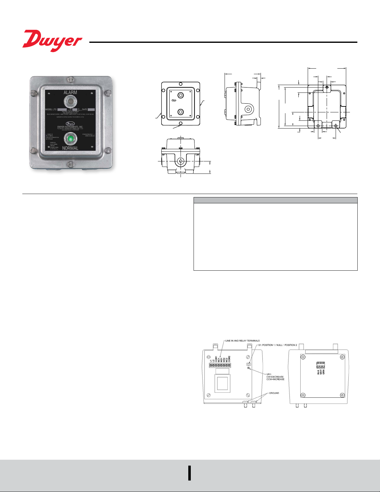
Series LTC Tilt Switch Control Unit
3X Ø.406
5.994 [152]
POWER OR RELA
®
Specications - Installation and Operating Instructions
Bulletin L-29
ALARM
WIRING ENTRY
The SERIES LTC Tilt Switch Control Units feature an adjustable time delay and a
logic selector switch. There are three contacts for connection to the probe; three
for the input power; and two sets of output contacts, each with one normally open,
one normally closed, and one common. Signal lights, relay, and transformer are all
accessible with the box cover open allowing for easy maintenance. The controller
output is through a relay, which provides a change in contacts as the probe moves
from vertical to tilt and vice versa. The user may choose to employ either the normally
open, normally closed, or both sets of contacts to perform switching operations in the
system. In addition, an adjustable time-delay feature may be assigned to either the
vertical or the tilt position to prevent false signals. The time delay is adjustable from
one to ten (0.1 to 35) seconds. The relay assumes the de-energized position upon
reaching the end of the delay period-as well as upon failure of power to the controller.
INDICATOR LIGHTS
Normal (green): Light on when relay is energized; probe is vertical.
Alarm (red): Light on when relay is de-energized; probe is tilted.
WIRING
All wiring should be in compliance with applicable Local, Federal, and State codes.
Cable is connected to the probe.
For the control unit LTC2, there are 2 conduit entries for relay and input power wiring,
and 1 conduit entry for probe wiring.
INSTALLATION INSTRUCTIONS
Y
POWER OR RELAY
WIRING ENTRY
NORMAL
1.251
[32]
1.375
[35]
2.750
[70]
1.251
[32]
[10]
5.610 [142]
PROBE
WIRING
ENTRY
Control Unit
1.934 [49]
SPECIFICATIONS
Temperature Limit: -4 to 104°F (-20 to 40°C).
Power Requirement: 115 VAC @ 50/60 Hz.
Power Consumption: 10W.
Switch Type: DPDT.
Electrical Rating: 5 A @ 120 VAC; 5 A @ 240 VAC.
Enclosure: Cast aluminum.
Enclosure Rating: None or NEMA 4, 4X.
Electrical Connections: No sufx: 120 VAC; B sufx: 240 VAC.
Conduit Connections: 3/4 NPT: 2 power/relay & 1 probe.
Indication Light: Green (when relay is energized and probe vertical), Red (when
relay is de-energized and probe tilted) (LED lamps).
Time Delay: 0.1 to 35 sec, adjustment will delay output relay action.
Figure 1: CONTROL UNIT CIRCUIT
PROBE INSTALLATION
The probe should be suspended using a xed support, such as a mounting bracket
and S-hook, at a position where it will easily intercept the bulk material at the desired
indication point. Note: up to 5000 ft of probe cable may be used. There must be a free
ow of material both to and away from the probe. In some installations, it is necessary
to install a bafe or shield above the probe assembly to protect it from product surges.
.567 [14]
6.746
[171]
6.000
[152]
1.185 [30]
2.125
[54]
1.188
[30]
MOUNTING
The control unit should be mounted in an area free from vibration and the temperature
should not exceed ambient (surrounding air) temperature limit: 104°C/104°F.
Consideration should be given to mounting the unit where indicator lights will be visible
to the necessary personnel, and wiring may be easily installed to the probe and other
machinery.
LOGIC SELECTOR
This jumper determines when the output relay actuates and de-actuates. The following
summarizes the operation with the jumper at each position.
Position 1: Relay energizes when probe is in the vertical position.
Relay de-energizes when probe is in the tilted position.
Position 2: Null (not used).
Position 3: Relay energizes when probe is in the tilted position.
Relay de-energizes when probe is in the vertical position.
©Copyright 2015 Dwyer Instruments, Inc. Printed in U.S.A. 11/15 FR# 443489-00 Rev. 3
DWYER INSTRUMENTS, INC.
P.O. BOX 373 • MICHIGAN CITY, INDIANA 46360, U.S.A.
MAINTENANCE
The Series LTC Tilt Probe Control Units are not eld serviceable and should be
returned if repair is needed (eld repair should not be attempted and may void
warranty). Be sure to include a brief description of the problem plus any relevant
application notes. Contact customer service to receive a return goods authorization
number before shipping.
Phone: 219/879-8000
Fax: 219/872-9057
www.dwyer-inst.com
e-mail: [email protected]
 Loading...