

Page 1
omega.com
e-mail: [email protected]
For latest product manuals:
omegamanual.info
JBOX-4800
Summing Box/Transmitter
Shop online at
User’s Guide
Page 2

Servicing North America:
U.S.A.: Omega Engineering, Inc., One Omega Drive, P.O. Box 4047
ISO 9001 Certified Stamford, CT 06907-0047 USA
Canada: 976 Bergar
Laval (Quebec), H7L 5A1 Canada
Toll-Free: 1-800-826-6342 TEL: (514) 856-6928
FAX: (514) 856-6886 e-mail: [email protected]
For immediate technical or application assistance:
U.S.A. and Canada: Sales Service: 1-800-826-6342/1-800-TC-OMEGA
®
Customer Service: 1-800-622-2378/1-800-622-BEST
®
Engineering Service: 1-800-872-9436/1-800-USA-WHEN
®
Mexico/ En Español: 001 (203) 359-7803 FAX: 001 (203) 359-7807
Latin America: [email protected] e-mail: [email protected]
Servicing Europe:
Benelux: Managed by the United Kingdom Office
Czech Republic: Frystatska 184
733 01 Karviná, Czech Republic
Toll-Free: 0800-1-66342 TEL: +420-59-6311899
FAX: +420-59-6311114 e-mail: [email protected]
France: Managed by the United Kingdom Office
Toll-Free: 0800 466 342 TEL: +33 (0) 161 37 29 00
FAX: +33 (0) 130 57 54 27 e-mail: [email protected]
Germany/Austria: Daimlerstrasse 26
D-75392 Deckenpfronn, Germany
Toll-Free: 0800 6397678 TEL: +49 (0) 7056 9398-0
FAX: +49 (0) 7056 9398-29 e-mail: [email protected]
United Kingdom: OMEGA Engineering Ltd.
ISO 9001 Certified One Omega Drive, River Bend Technology Centre, Northbank
Irlam, Manchester M44 5BD United Kingdom
Toll-Free: 0800-488-488 TEL: +44 (0) 161 777-6611
FAX: +44 (0) 161 777-6622 e-mail: [email protected]
OMEGAnet®Online Service Internet e-mail
omega.com [email protected]
It is the policy of OMEGA Engineering, Inc. to comply with all worldwide safety and EMC/EMI
regulations that apply. OMEGA is constantly pursuing certification of its products to the European New
Approach Directives. OMEGA will add the CE mark to every appropriate device upon certification.
The information contained in this document is believed to be correct, but OMEGA accepts no liability for any
errors it contains, and reserves the right to alter specifications without notice.
WARNING: These products are not designed for use in, and should not be used for, human applications.
Page 3

J B o x - 4 8 0 0
SUMMING BOX / TRANSMITTER
OPERATIONAL MANUAL
I. GENERAL DESCRIPTION
1. Features ................................................................2
2. Application .............................................................2
3. Brief Description ....................................................3
4. Operation ..............................................................3
5. Specication ..........................................................4
6. Instrument layout ...................................................5
II. INSTALLATION
1. Item check list .......................................................7
2. Mounting ...............................................................7
3. Electrical Connections ...........................................7
III. SETUP
1. Setting the Excitation Voltage .............................10
2. Single Load Cell System Adjustment ..................10
3. Multiple Load Cell System Adjustment ................10
4. Troubleshooting ...................................................12
IV. OPTIONS
1. Enclosures ..........................................................14
2. Dual Set Points
(Installation and Setup) .......................................14
3
Page 4

J Bo x - 4 8 0 0
SUMMING BOX / TRANSMITTER
I. GENERAL DESCRIPTION
1. Features
• Summing of up to 4 load cells
• Complete strain gage bridge signal conditioner
• Highgain,lowdrift,lowtemperaturecoefcientprecisionampliers,withlow
input current 10 pA typical)
• Wide input range from 5 mV to 50 mV full scale
• Very stable bridge balance with 80% tare offset capability
• 4-20 mA or 0-20 mA output
• 2 to 10 V or 0 to 10 V output
• Excitation supply capable of driving four load cells
○ Typical0.001%temperaturecoefcient
○ Wideadjustmentvoltagerange
○ Longdistanceremotesensecapability
○ Verygoodlineandloadregulation
• Both AC and DC power capability
• Input, output and power three way isolation
• NEMA 4 enclosure for use in rugged environments
2. Application
• Precision weighing with load cells
• Process control add-on loops
• Can be used with all types of low output sensors
USER’S GUIDE
3. Brief Description
The JBox-4800 is an AC or DC powered Summing Transmitter for up to four load cells with output
optionsof0to20mA,and0to 10 Vor4to20 mA, and2to10V.Allinput/outputoptionsare
includedononeboardsothereisnoneedtospecifyinput/outputparameterswiththeJBox-4800.
The JBox-4800 has a built in excitation supply capable of delivering up to 120 mA from 5 to 10 V,
morethanenoughcurrenttodrivefour350ohmloadcells.
The JBox-4800 offers three way isolation, input to output and power, eliminating unwanted ground
loopproblems.Overallaccuracyoverthenormalroomtemperaturerangeisexcellentat<±0.1%
offullscale.Thehighgain,verylowdriftandverylowtemperaturecoefcientofthe4800amplier
allowsfullscaleliveloadsignalsaslowas5mVtobeampliedto20mAor10V.
Designed with large and very stable tare offset requirements, the JBox-4800 can tare off up to 80%
oftheoutputofa3mV/Vloadcell(at10Vexcitation).
If high/low setpoint alarms/controls are desired, the JBox-4800 board is laid out to accept Opto-22 output
relays.Potentiometersareaccessibletoadjustthehighandlowtrippoints.
4. Operation
The JBox-4800 accepts DC mV signals from up to four load cells which are summed together, then
amplied,isolatedandltered.TheJBox-4800featuresa verystableon-boardexcitation supply
andprecisionamplier.Theyaredesignedforverylowdrift andasmalltemperaturecoefcient,
criticalforhighaccuracy.Thefullscaleoutputiseithera20mAor10Vsignalforindustrialcontrol.
AwideACandDCpowervoltagerangeisallowedforconvenience.
4
Page 5

J B o x - 4 8 0 0
SUMMING BOX / TRANSMITTER
5. Specications
NOTE:Unlessotherwisenoted,specicationsapplyaftera30minutewarmupat23ºC±2ºC
ambient.TemperatureCoefcientsapplybetween0ºCand55ºCambient.
ACCURACY
10to35ºC,at10VExcitation Lessthan±0.1%
TotalTemperatureCoefcient(TC) 0.0025%/ºCtyp
ISOLATION
AC or DC Powered - Three Way Isolated
AC to Input and Output 750 VAC
DC to Input to Output 300 VDC
AMPLIFIER SECTION
Gain
Input Range 5 mV to 50 mV Full Scale
Linearity ±0.01%ofFullScale
TC 0.0015%/ºCtyp
InputNoise-0.1Hzto10Hz 2 µV PP
TareAdjustmentRange -3mVto+6.5mV
(Bridge Offset) +6.5mVto+16mV
(Equals80%F.Sof3mV/Vcellat10V) +16 mV to +25 mV
TemperatureCoefcient 0.0015%/ºCtyp
CommonModeRejection 100 dB Min
Common Mode Input Voltage +5 Volts Max
OUTPUT
Zero Selection 0 or 4 mA
TemperatureCoefcient 0.001%/ºCtyp
Test Signal Output Add 8 mA or 4 V to output
Current Output Span
Current 0 or 4 to +20 mA
Compliance Voltage 0 to +20 Volts
Loop Resistance 0 to 1000 ohms
Voltage Output Span
Voltage 0 or 2 to 10 V
Maximum Load Current 5 mA
Frequency Response
2 Poll roll off -3dBat10Hztyp
Response Time
Rise Time 10% to 90% 35 mS
To0.1%ofFinalvalue 100 mS
USER’S GUIDE
500 pF
0 or 2 V
Available0to-0.3mAforzeromonitor
Available -2 to 10 V
5
Page 6

J B o x - 4 8 0 0
SUMMING BOX / TRANSMITTER
COMPARATOR OUTPUT Optional with Opto22 I/O Module
Comparative Voltage 0 to 10 V
Hysteresis Voltage 0.07Vtyp
Comparator Output seethespecicationofOPTO22
Input/Output Isolation 300 V
BRIDGE EXCITATION SUPPLY
VoltageAdjustmentRange 5 to 10 V
TemperatureCoefcient 0.001%typat10V
Load Current 0 to 120 mA
Remote Sense for Excitation Supply
Current Leads Volts Drop Max 1 V drop
Sensing Leads Resistance Max 1 kohm
Line Regulation Lessthan0.01%,typ0.002%
Load Regulation Lessthan0.03%,typ0.005%
Output Noise
120HzBandwidth
POWER INPUT
AC 115 V (90 to 130 V) /
DC 11 to 30 V, 8 W
ENVIRONMENT
Operating Temperature -25ºCto+55ºC
Storage Temperature -25ºCto+85ºC
WEIGHT
JUNCTION BOX
TOTAL SIZE
USER’S GUIDE
output module
1 mV RMS, typ
LED power on indicator
230 V (180 to 260 V)
50/60Hz,10Wtyp
10.5lb(4.7kg)
10” L x 8” W x 4” H, NEMA 4 Box
or NEMA 4X Stainless Steel Box
12.5”x9”x4.4”
(318 mm x 229 mm x 112 mm)
6. Instrument Layout
The components are assembled on one printed circuit board which is mounted inside of a NEMA 4
box.TheT&BNon-MetallicLiquidtightStrainReliefConnectorsareusedforweatherproongand
corrosionresistance.Fourconnectorsononesideoftheboxareusedforloadcellconnections.
Two connectors on another side of the box are used for output signals, relay outputs and power
connections.
6
Page 7
J B o x - 4 8 0 0
SUMMING BOX / TRANSMITTER
USER’S GUIDE
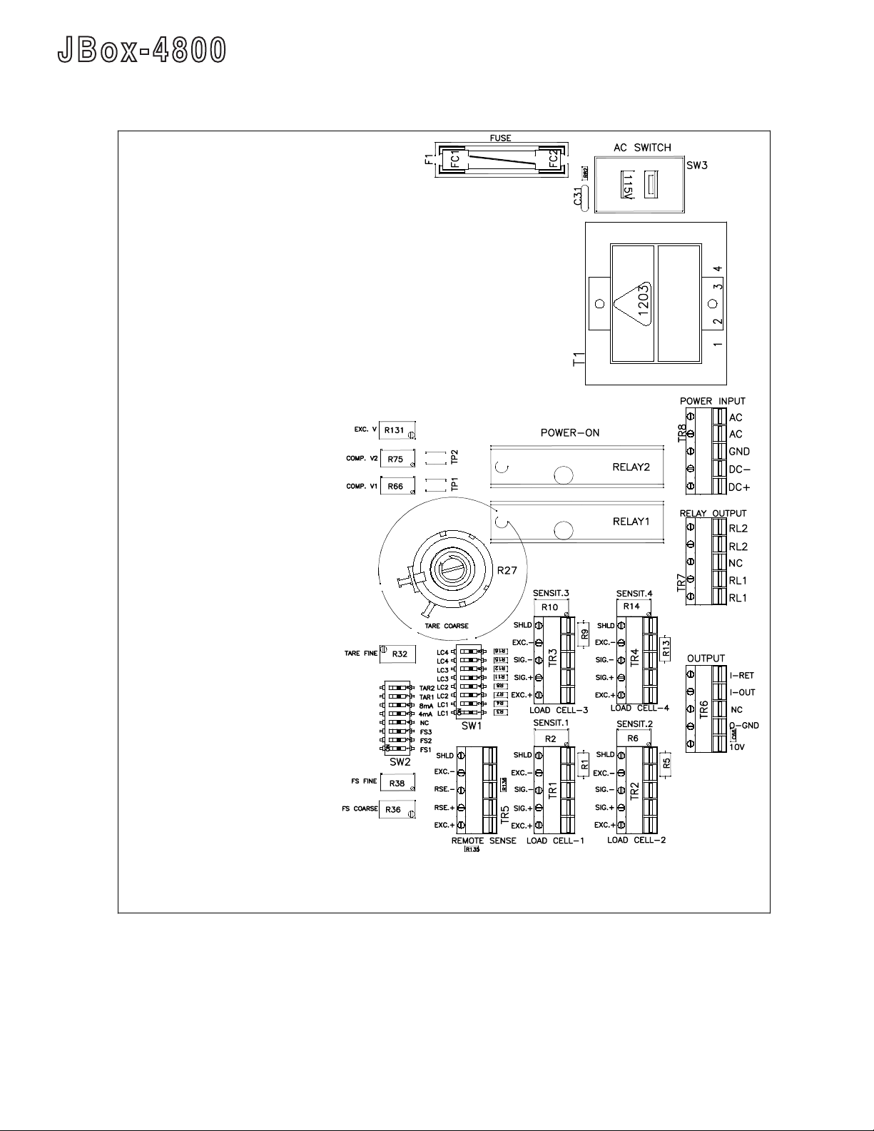
JBox-4800 Adjustment Locations
Relays 1 and 2 are installed by customer
7
Page 8

J B o x - 4 8 0 0
SUMMING BOX / TRANSMITTER
II. INSTALLATION
1. UnpackingtheJBox-4800
A. ItemCheckList
√JBox-4800LoadCellSummingTransmitter
√ACPowerCord
√GroundingKitforNEMA4Box
√OperationManual
√HolePlugs
2. Mounting
Mount the NEMA 4 Box using four screws in a location where water will not drip or run directly
ontoit.
Connecttheboxtothescaleframeworkgroundusingthe“GroundingKit” and alowresistance
groundstrap(e.g.#10orlargerwire).Aterminal“GND”on“Power Input” connector canalsobe
usedforgroundconnection.
3. Electrical Connection
Note: All the terminals are marked clearly on the printed circuit board. Be sure all terminal strip
connections are tight and the cable conductors are not cut or damaged. Use strain relief connectors,
tighten securely. Remove any unused strain reliefs and replace with provided hole plugs.
USER’S GUIDE
A. Connect the power to JBox-4800
If you use AC power line, connect the two AC power leads to “AC” pin and ground lead to “GND”
pin.Setthe“ACSwitch”toyourpowerlinevoltage(115Vor230V)beforeyoupluginthepower
cord.
If you use DC power, connect the DC power supply plus lead to “DC+” pin and negative lead
to“DC-”pin.
B. Pre-set the excitation voltage
Connect“RSE.+”(Remotesensing)to“EXC+”(Excitation),on“RemoteSense”connector
“TR5”,andconnect“RSE.-”to“EXC.-”.
TurnonthepowertoJBox-4800.Measurethevoltageattheremotesensingpins.Adjustthe
excitationsupplyvoltagewiththe“EXC.V”potentiometer“R131”.
Thisstepisnecessarytoavoidoverdrivingtheloadcells.
Note that all four load cell connectors “TR1-4” use the same excitation supply in parallel, so
theexcitationsupplyvoltageisalwaysadjustedat“EXC.V”potentiometer“R131”regardless
ofthenumberofcells.
*CAUTION: Turn off the power!
8
Page 9
J B o x - 4 8 0 0
SUMMING BOX / TRANSMITTER
C. Connect the load cells to the JBox-4800
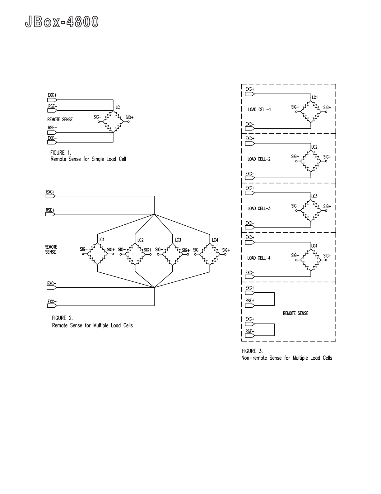
“EXC.+”and“EXC-.”pinsseeFig.1toFig.3fordifferentapplications.
USER’S GUIDE
D. Remote Excitation
ExcitationSupply isa highperformance, remotesensing supplyfor longlead applications.
Remote sensing mode is recommended for single load cell applications and also for up to four
loadcellapplicationswherelongleadsarepresent.
Thetotalvoltagedropofexcitationleadsshouldbelessthan1V.Anapplicationexample:if
excitationleadsarecopperwireAWGno. 16,1000feet resistanceis4.016 ohm,roundtrip
resistanceis8.032ohm,thenthevoltagedropat120mAexcitationcurrentislessthan1V.
Ifremotesensingisdesired,disconnect“RSE.+”from“EXC.+”,on“RemoteSense”connector
“TR5”,anddisconnect“RSE.-”from“EXC.-”
9
Page 10

J B o x - 4 8 0 0
SUMMING BOX / TRANSMITTER
Connect“RSE.+”and“RSE.-”totheexcitationleadswhereyouwantthevoltagetobecontrolled.
Usuallythesetwopointsareclosetotheloadcell.SeeFig.2forsingleloadcellandFig.3for
multipleloadcellconnections.
If remote sensing is not used, skip step D.
E. Connecteachloadcelltotherelatedamplierinputpins
“SIG.+”and“SIG-.”onconnectors“LoadCell-1”to“LoadCell-4”.
Ifasingleloadcellisused,connectitto“LoadCell-1”connector.(Otherconnectors“LoadCell2to4”andswitch“LC2to4”canalsobeused.)
AllwiresusedinconnectinguptheJBox-4800shouldbeofthesamematerial.Ifanyintervening
connectionshavetobemade,suchasaterminalblock.Theterminalblockconnectingpoints
shouldhavegoodthermalcontactsotheywillalwaysbeatthesametemperaturetominimize
thermal-electriceffects.
F. “SW1” has eight dip switches for four load cells.
Turnontwoswitches“LC1”on“SW1”.Thisconnectsthecelloutputsignalstotheamplier
input.
G. We strongly recommend you use the JBox4800 excitation supply to
ensure high accuracy.IncasetheamplierisusedwithouttheJBox-4800
excitation supply, the external power supply low side must be connected to the
“EXC.-”terminalon“RemoteSense”connector.
USER’S GUIDE
III. Setup
1. Setting the Excitation Voltage
A. Turn on power to the JBox-4800
B. Measure the voltage at the remote sensing points or at the sense terminal
on“RemoteSense”connector.Adjusttheexcitationsupplyvoltagewiththe
“EXC.V”potentiometer“R131”.
2. Single Load Cell System Adjustment
A. Selecttheexpectedfullscalesignalrangeaccordingtotable1withSW2-
”FS1”,“FS2”and“FS3”.Iftheoutputfromtheloadcellisnotknown,setSW2
forthe40-50mVrange.
Table 1. Input Range Selection for Full Scale
Range 0-20 mA /
0-10 V
1 5 to 10 mV 5 to 8 mV OFF OFF OFF
2 10 to 20 mV 8 to 16 mV OFF OFF ON
3 20 to 40 mV 16 to 32 mV OFF ON ON or OFF
4 40 to 50 mV 32 to 50 mV ON ON or OFF ON or OFF
B. Select Zero Output
SetSW2-”4mA”onfor4mAor2VoutputorSW2-”4mA”offfor0mAor0Voutput.Noteactual
outputmaynotequaldesiredvalue,followthestepsbelowforadjustment.
2-10 V /
4-20 mA
FS1 FS2 FS3
10
Page 11

J B o x - 4 8 0 0
SUMMING BOX / TRANSMITTER
C. Select Tare Range on “SW2” according to Table 2.
D. Apply no load or dead weight to load cell.
E. For voltage output connect:
Connect the “Hi” lead of a digital voltmeter to the “10V”, connect the “Lo” lead of the digital
voltmetertothe“O-GND”of“OUTPUT”connector“TR6”.
For current output: Connect the “Hi” lead of a current meter to the “I-OUT”, connect the
“Lo” lead of the current meter to the current return terminal “I-RET” of “OUTPUT” connector
“TR6”.
Therewillbeasmalldifferencebetweencurrentoutputandvoltageoutput.Selectcurrent
orvoltageoutputforadjustment.
USER’S GUIDE
Table 2. Tare Range Selection
TARE 1 TARE 2
-3to6.5mV OFF OFF
6.5to16mV OFF ON
16 to 25 mV ON ON or OFF
F. Adjust “TARE COARSE” and “TARE FINE” potentiometers for the ZERO
current(0to4mA)orZEROvoltage(0to2V).
G. Test signal: Turn on Switch “SW2”-”8mA” to output a change of 8 mA or 4 V
formonitoringsystemcheck.SeeTable3.
Table 3. Calibration Output Selection
“SW2” - “4 mA” OFF “SW2” - “4mA” ON
“SW2” - “8 mA” OFF 0 4 mA and/or 2 V
“SW2” - “8 mA” ON 8 mA and/or 4 V 12 mA and/or 6 V
Turn “SW2”-”8mA” off, after the completion of system check
H. Apply rated load cell full scale load. Adjust“SENSIT.1”(“R2”)togetthe
maximumsensitivity.
I. Apply rated load cell full scale load. Adjust“FSCOARSE”and“FSFINE”
(GAIN)potentiometersforthedesiredfullscaleoutputvoltageorcurrent.Set
fullscalerangeswitchesasrequiredinTable2.
J. Remove full scale load and check ZERO output voltage or current.Adjust
“TAREFINE”potentiometerifrequired.
K. Recheck full scale as in step 2.I.
3. Multiple Load Cells Adjustment (Cornering the scale)
Note: The full scale weight of a system with multiple load cells is the multiple of
rated full scale of each load cell.
A. Turn on two “SW1”-”LC1” switches only, turn off other “SW1” switches.
Followsteps2.Ato2.I.Note:Applyaloadof20to100%oftheratedfullscalecapacityofeach
loadcell(notthefullscaleofsystem)forcorneradjustment.Recordtheoutputvoltagewith
andwithoutload.
11
Page 12

J B o x - 4 8 0 0
SUMMING BOX / TRANSMITTER
B. Turn on two “SW”1-”LCn” (n=2, 3 or 4) switches only, turn off all other “SW1”
switches.Applysameloadasinstep1.Adjust“SENSIT.n”togetthemaximumsensitivity.
Recordtheoutputvoltageswithandwithoutloadforeachloadcell.
C. Calculatethespan,thedifferenceofoutputvoltagebetweennoloadandloadedforeach
cornerloadcell.
Thesensitivityadjustmentrangefor350ohmloadcellsis7%.Ifthespreadofthedifferenceof
output voltage between corner load cells is larger than 7%, check the mechanical installation of
loadcellsandthespecicationsofloadcells,Usuallythecornerloadcellsshouldbematched
toeachotherwithin±3%.
D. Selectthelowestcelloutputspanasthespanreference.
Donotadjusttheloadcellsensitivitypotforthiscell.
Turnontwo “SW1”-LCn”(n=1,2, 3or4) switchesonly.Turnoff allother“SW1” switches.
Applynoloadand20%to100”offullscaleofloadcell(Notsystemfullscale).Adjust“Sensit.
n” potentiometer to lower down the sensitivity for the output span to be the same value as span
referencevoltage.
E. If there is no way to put known weight on each corner, apply 20 to 100% of full scale of
system load instead of 20 to 100% of fullscaleofloadcell.ThenfollowthestepsAtoD.
F. Turnonall“SW1”-LC1”,“LC2”....”LCn”switcheswhichareused.
RemoveallloadandcheckZEROoutputvoltageorcurrent.Adjust“TARE
COARSE”and‘TAREFINE”potentiometerforzerooutput.
USER’S GUIDE
G. Applyratedsystemfullscaleload.Adjust“FSCOARSE”and“FSFINE”
(GAIN)potentiometersforthedesiredfullscaleoutputvoltageorcurrent.Set
fullscalerangeswitchesasrequiredinTable2.
H.Ifnecessary,repeatstep3.Eand3.F.
Note: Do not try to equalize the dead load outputs of each cell. The dead load does not need
to be the same for proper operation of the summing board.
12
Page 13

J B o x - 4 8 0 0
SUMMING BOX / TRANSMITTER
4. Troubleshooting
A. The scale seems to be reading incorrectly
a. Checkforcorrectwiring.
b.Unloadthescaleandcheckforazeroreading.
c. ChecktheinputrangeswitchesaccordingtoTable2.
d. Besurethattheobjectbeingweighediscompletelyonthescale.
B. The scale corner readings are not equal
a. Repeatstep3.Multipleloadcellsadjustment.
b. Checktheinstallationofloadcells
c. Checktheloadcellsfordamage.
C. The scale readings drift rapidly
a.Checkforwaterinthejunctionbox.
b. Isolateoneloadcellatatimefromthesummingboxbyturningoffthetworelatedswitches
“LCn”(n=1to4).Ifthescalereadingbecomesstable,thentheisolatedloadcellisprobably
defectiveornotinstalledproperly.
c. UsealoadcellsimulatortoverifythattheJBox-4800isstableandoperatingcorrectly.
USER’S GUIDE
D. Test the load cell zero shift
a. Removetheloadfromtheloadcell.
b. Turnonthetworelatedswitches“LCn”,turnoffallotherswitches.
c. Measuretheoutputvoltageon“output:connector.Ifitislessthan15%offullscaleoutput,
itisnotzeroshifted.Iftheoutputis15to50%offullscale,theloadcellhasbenezero
shifted,butwillprobablystillwork.Iftheoutputislargerthan50%offullscale,theload
cellshouldbereplacedwithaknowngoodunit.Ifthezeroshiftoftheloadcelliscaused
by a mechanical overload, the reason for the overload should be determined before a new
loadcellisinstalled.
E. Test load cell resistance
a.Disconnecttheloadcellsfromthejunctionbox.
b. Measuretheresistancesofloadcellandcomparetotheloadcellspecications.Water
leakageintotheloadcellordamagedcablecancauseproblems.
c. Ifaloadcelldoesnotpasstheresistancetest,replaceitwithaknowgoodunit.
d. Defectiveloadcellscanusuallyberepaired.
13
Page 14

J B o x - 4 8 0 0
SUMMING BOX / TRANSMITTER
IV. OPTIONS
1. Enclosures
JBox-4800: Continuous Hinge NEMA 4 Box
2. Dual Set Point Relays
A. Opto-22 G4ODC5 *
Opto-22 G4OAC5 *
*Not included with the JBox-4800
B. Installation
PlugtheOpto-22outputmodulesinto“RELAY1and“RELAY2”ontheprintedcircuitboard.
Tightenthescrewontopofthemodulelightly.
C. Adjusting Set Point Values
IfyouneedtheRelayoutputs,connectthe“Hi”leadofadigitalvoltmetertothe“TP1”.Connect
the“Lo”leadofthedigitalvoltmetertothe“O-GND”on“OUTPUT”connector“TR6”.Testthe
voltageat“TP1”andadjustthe“COMP.V1”potentiometer“R66”tosettheComparatorvoltage
forthe low setpoint. Ifthe outputvoltageat “OUTPUT”connector “TR6”islower thanthe
Comparator voltage at “TP1”, this means the output is lower than the low set point, and the
outputofRelay1willbe“ON”.Thetwo“RL1”on“RELAYOUTPUT”connector“TR7”arethe
Opto-22Outputcontacts.
USER’S GUIDE
Use the digital voltmeter to set the voltage at “TP2”with “COMP.V2” potentiometer “R75”
forhighsetpoint.Iftheoutputvoltageat“OUTPUT”onconnector“TR6”ishigherthanthe
Comparator voltage at “TP2”, this means the output is higher than high set pint, and the output
ofRelay2willbe“ON”.Thetwo“RL2”on“RELAYOUTPUT”connector“TR7”aretheOpto-22
Outputcontacts.
Inordertopreventrelaychatter,typicallythereare0.07Vhysteresisvoltage.Theremaybea
very small difference between the output voltage and the voltage at “TP1” or “TP2” for turn on
oroff.Theoutputvoltageforturnonoroffcanbesetpreciselybyadjustingthe“COMP.V1”
potentiometer“R66”forthelowsetpointor‘COMP.V2”potentiometer“R75”forhighsetpoint.
14
Page 15

WARRANTY/DISCLAIMER
OMEGA ENGINEERING, INC. warrants this unit to be free of defects in materials and workmanship for a
period of 13 months from date of purchase. OMEGA’s WARRANTY adds an additional one (1) month
grace period to the normal one (1) year product warranty to cover handling and shipping time. This
ensures that OMEGA’s customers receive maximum coverage on each product.
If the unit malfunctions, it must be returned to the factory for evaluation. OMEGA’s Customer Service
Department will issue an Authorized Return (AR) number immediately upon phone or written request.
Upon examination by OMEGA, if the unit is found to be defective, it will be repaired or replaced at no
charge. OMEGA’s WARRANTY does not apply to defects resulting from any action of the purchaser,
including but not limited to mishandling, improper interfacing, operation outside of design limits,
improper repair, or unauthorized modification. This WARRANTY is VOID if the unit shows evidence of
having been tampered with or shows evidence of having been damaged as a result of excessive corrosion;
or current, heat, moisture or vibration; improper specification; misapplication; misuse or other operating
conditions outside of OMEGA’s control. Components in which wear is not warranted, include but are not
limited to contact points, fuses, and triacs.
OMEGA is pleased to offer suggestions on the use of its various products. However,
OMEGA neither assumes responsibility for any omissions or errors nor assumes liability for any
damages that result from the use of its products in accordance with information provided by
OMEGA, either verbal or written. OMEGA warrants only that the parts manufactured by the
company will be as specified and free of defects. OMEGA MAKES NO OTHER WARRANTIES OR
REPRESENTATIONS OF ANY KIND WHATSOEVER, EXPRESSED OR IMPLIED, EXCEPT THAT OF
TITLE, AND ALL IMPLIED WARRANTIES INCLUDING ANY WARRANTY OF MERCHANTABILITY
AND FITNESS FOR A PARTICULAR PURPOSE ARE HEREBY DISCLAIMED. LIMITATION OF
LIABILITY: The remedies of purchaser set forth herein are exclusive, and the total liability of
OMEGA with respect to this order, whether based on contract, warranty, negligence,
indemnification, strict liability or otherwise, shall not exceed the purchase price of the
component upon which liability is based. In no event shall OMEGA be liable for
consequential, incidental or special damages.
CONDITIONS: Equipment sold by OMEGA is not intended to be used, nor shall it be used: (1) as a “Basic
Component” under 10 CFR 21 (NRC), used in or with any nuclear installation or activity; or (2) in medical
applications or used on humans. Should any Product(s) be used in or with any nuclear installation or
activity, medical application, used on humans, or misused in any way, OMEGA assumes no responsibility
as set forth in our basic WARRANTY/DISCLAIMER language, and, additionally, purchaser will indemnify
OMEGA and hold OMEGA harmless from any liability or damage whatsoever arising out of the use of the
Product(s) in such a manner.
RETURN REQUESTS/INQUIRIES
Direct all warranty and repair requests/inquiries to the OMEGA Customer Service Department. BEFORE
RETURNING ANY PRODUCT(S) TO OMEGA, PURCHASER MUST OBTAIN AN AUTHORIZED RETURN
(AR) NUMBER FROM OMEGA’S CUSTOMER SERVICE DEPARTMENT (IN ORDER TO AVOID
PROCESSING DELAYS). The assigned AR number should then be marked on the outside of the return
package and on any correspondence.
The purchaser is responsible for shipping charges, freight, insurance and proper packaging to prevent
breakage in transit.
FOR WARRANTY
RETURNS, please have the
following information available BEFORE
contacting OMEGA:
1. Purchase Order number under which the product
was PURCHASED,
2. Model and serial number of the product under
warranty, and
3. Repair instructions and/or specific problems
relative to the product.
FOR NON-WARRANTY REPAIRS,
consult OMEGA
for current repair charges. Have the following
information available BEFORE contacting OMEGA:
1. Purchase Order number to cover the COST
of the repair,
2. Model and serial number of the product, and
3. Repair instructions and/or specific problems
relative to the product.
OMEGA’s policy is to make running changes, not model changes, whenever an improvement is possible. This affords
our customers the latest in technology and engineering.
OMEGA is a registered trademark of OMEGA ENGINEERING, INC.
© Copyright 2011 OMEGA ENGINEERING, INC. All rights reserved. This document may not be copied, photocopied,
reproduced, translated, or reduced to any electronic medium or machine-readable form, in whole or in part, without the
prior written consent of OMEGA ENGINEERING, INC.
Page 16

M3279/0411
Where Do I Find Everything I Need for
Process Measurement and Control?
OMEGA…Of Course!
Shop online at omega.com
SM
TEMPERATURE
䡺⻬
Thermocouple, RTD & Thermistor Probes, Connectors, Panels & Assemblies
䡺⻬
Wire: Thermocouple, RTD & Thermistor
䡺⻬
Calibrators & Ice Point References
䡺⻬
Recorders, Controllers & Process Monitors
䡺⻬
Infrared Pyrometers
PRESSURE, STRAIN AND FORCE
䡺⻬
Transducers & Strain Gages
䡺⻬
Load Cells & Pressure Gages
䡺⻬
Displacement Transducers
䡺⻬
Instrumentation & Accessories
FLOW/LEVEL
䡺⻬
Rotameters, Gas Mass Flowmeters & Flow Computers
䡺⻬
Air Velocity Indicators
䡺⻬
Turbine/Paddlewheel Systems
䡺⻬
Totalizers & Batch Controllers
pH/CONDUCTIVITY
䡺⻬
pH Electrodes, Testers & Accessories
䡺⻬
Benchtop/Laboratory Meters
䡺⻬
Controllers, Calibrators, Simulators & Pumps
䡺⻬
Industrial pH & Conductivity Equipment
DATA ACQUISITION
䡺⻬
Data Acquisition & Engineering Software
䡺⻬
Communications-Based Acquisition Systems
䡺⻬
Plug-in Cards for Apple, IBM & Compatibles
䡺⻬
Data Logging Systems
䡺⻬
Recorders, Printers & Plotters
HEATERS
䡺⻬
Heating Cable
䡺⻬
Cartridge & Strip Heaters
䡺⻬
Immersion & Band Heaters
䡺⻬
Flexible Heaters
䡺⻬
Laboratory Heaters
ENVIRONMENTAL
MONITORING AND CONTROL
䡺⻬
Metering & Control Instrumentation
䡺⻬
Refractometers
䡺⻬
Pumps & Tubing
䡺⻬
Air, Soil & Water Monitors
䡺⻬
Industrial Water & Wastewater Treatment
䡺⻬
pH, Conductivity & Dissolved Oxygen Instruments
 Loading...