

Page 1
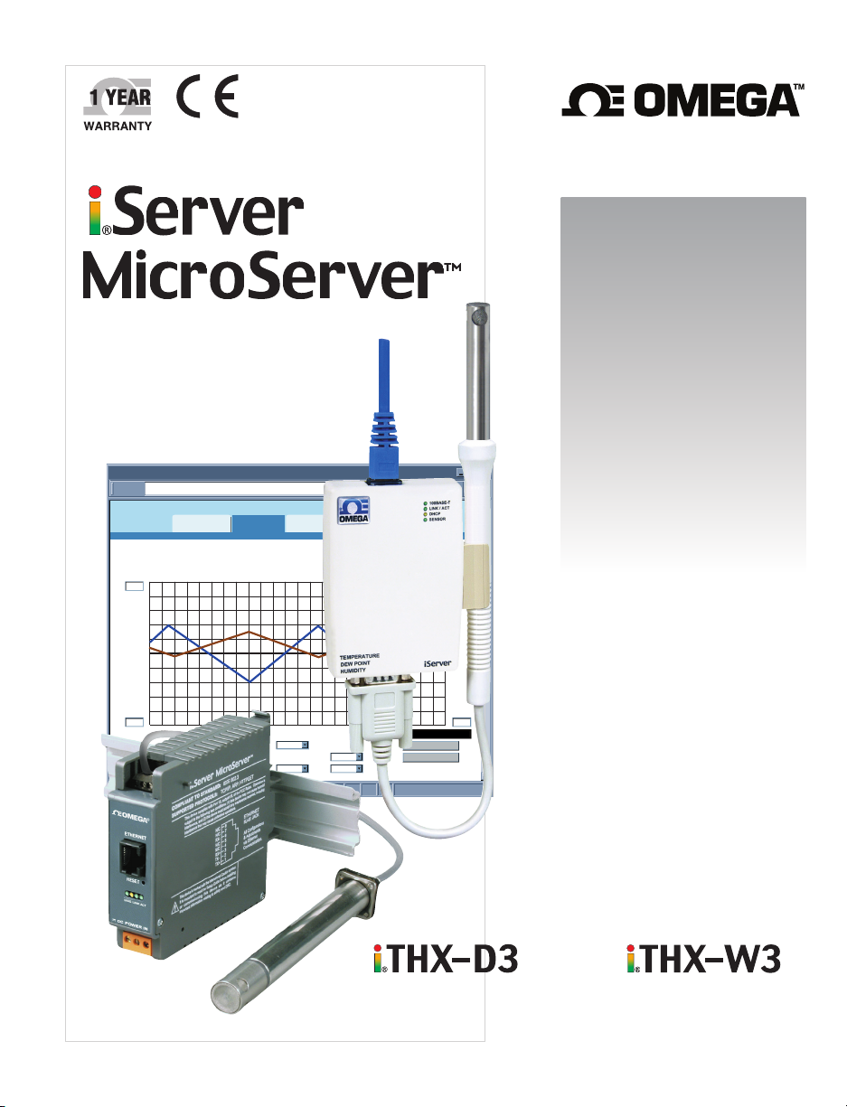
TM
User’s Guide
2!3/"
!""#$%%&'()&*+)&)(,,-../011
I03.9?N1 2!3/" T0U4P9?V A0"7#
<3=)4&>,)&4%4<9?)4'@)' <3=)4*')'4%4<9?)4>,)&
!"#$"%&'(%" )(#*+*',
(,,
(,),
2%89:
,
83"34A67/F0$
-G3/H4I0G3J4A0"4B69?"1$
50G#WXY
-./0123 4.0/25
P9:0
Q6G.
&4567/%89:
SL3=91$ &483J
KL3=914MG0R"O$ C0H#0/3"7/0 A"JG0$ Q6G.
KL3=914M/9N!"O$
57H9.9"J A"JG0$ Q6G.
C!74D6:4&+4&($,@$,E4B8C4(,&,C!74D6:4&+4,+$,,$,,4B8C4(,&,
A3:042!3/"
B/9?"42!3/"
Temperature + Humidity
&,,
omega.com
Shop online at
&,),
;%89:
,
e-mail: [email protected]
For latest product manuals:
www.omegamanual.info
and
Page 2

omega.com [email protected]
Servicing North America:
U.S.A. Omega Engineering, Inc.
Headquarters: 800 Connecticut Ave. Suite 5N01, Norwalk, CT 06854
Toll-Free: 1-800-826-6342 (USA & Canada only)
Customer Service: 1-800-622-2378 (USA & Canada only)
Engineering Service: 1-800-872-9436 (USA & Canada only)
Tel: (203) 359-1660 Fax: (203) 359-7700
For Other Locations Visit omega.com/worldwide
e-mail: [email protected]
The information contained in this document is believed to be correct, but OMEGA accepts no liability for any errors it contains, and reserves
the right to alter specifications without notice.
Page 3

i
TABLE OF CONTENTS
Part 1: Introduction
1.1 Safety and EMC Considerations .................................................................2
1.2 Before You Begin..........................................................................................2
1.3 Description....................................................................................................2
Part 2: Hardware
2.1 Mounting ......................................................................................................4
2.1.1 Mounting the Wall Mount iServer .................................................4
2.1.2 Mounting the DIN Rail iServer ......................................................5
2.1.3 Removal from DIN Rail ..................................................................5
2.2 Dimensions ...................................................................................................6
2.3 Parts of iServer Unit ....................................................................................7
2.4 Network Communication Interfaces ..........................................................8
2.4.1 10/100 BASE-T RJ-45 Pinout .........................................................8
2.4.2 Connecting iServer to PC/Hub/Switch/Router .............................8
2.5 Industrial Probe ............................................................................................8
Part 3: Network Configuration
3.1 Network Protocols .......................................................................................9
3.2 Ethernet (MAC) Address .............................................................................9
3.3 DHCP .......................................................................................................10
3.4 DNS .......................................................................................................10
3.5 IP Address ..................................................................................................10
3.6 Port Number................................................................................................11
Part 4: Operations
4.1 IP Address Assignment..............................................................................11
4.1.1 DHCP (Method 1)...........................................................................11
4.1.2 ARP HTTPget Commands (Method 2).........................................12
4.1.3 Direct Connection (Method 3)......................................................12
4.1.4 iConnect Software (Method 4) .....................................................16
4.2 Access and Configuration Using a Web Browser ..................................18
4.3 LOGIN and ADMINISTRATOR Passwords ...............................................18
4.4 Setup ........................................................................................................19
4.4.1 Overview........................................................................................19
4.4.2 Network..........................................................................................20
4.4.2.1 IP Configuration...............................................................20
4.4.2.2 Ethernet Port ....................................................................22
4.4.3 Configuration ................................................................................22
4.4.3.1 Data and Time ..................................................................22
4.4.3.2 Server................................................................................24
4.4.3.3 Sensors.............................................................................24
4.4.4 Management..................................................................................26
4.4.4.1 Setup.................................................................................26
4.4.4.1.1 Sending Text Messages to a Cell Phone ....................28
4.4.4.2 Alarms...............................................................................29
4.4.5 Security..........................................................................................30
Page 4

ii
4.4.6 System ...........................................................................................31
4.4.6.1 Reboot ..............................................................................31
4.4.6.2 Defaults.............................................................................32
4.4.6.3 Upgrade ............................................................................32
4.4.6.4 Download Configuration .................................................33
4.4.6.5 Upload Configuration ......................................................33
4.4.7 Diagnostics ...................................................................................34
4.4.8 Log Out ..........................................................................................34
4.5 Readings .....................................................................................................35
4.5.1 HTML..............................................................................................35
4.5.2 Java ...............................................................................................35
4.6 Chart ........................................................................................................36
4.7 Web Link......................................................................................................37
4.8 Telnet Setup ................................................................................................38
4.8.1 Telnet Connection.........................................................................38
4.9 HTTPget Program.......................................................................................39
4.9.1 HTTPget using Port 2000 .............................................................39
4.10 iLog Software..............................................................................................41
Part 5: Specifications .......................................................................................................43
Appendix A Glossary ......................................................................................................45
Appendix B IP Address ..................................................................................................46
Appendix C ARP Commands .........................................................................................47
Appendix D IP Netmask .................................................................................................48
Appendix E ASCII Chart ................................................................................................49
ASCII Chart Control Codes .......................................................................50
Appendix F iLog Error Messages .................................................................................51
Appendix G Java Runtime Environment Setup ...........................................................52
Appendix H Sensor Information ...................................................................................54
Appendix J SNMP .......................................................................................................56
Part 6: Approvals Information
6.1 Electromagnetic Compatibility (EMC) .....................................................57
6.2 FCC ........................................................................................................57
LIST OF FIGURES:
Figure 1.1 iServer with Probe on the Ethernet Network .......................................3
Figure 2.1 Mounting - Wall Mount iServer .............................................................4
Figure 2.2 Mounting - DIN Rail iServer ..................................................................5
Figure 2.3 Removal - DIN Rail iServer ..................................................................5
Figure 2.4 Mounting - Dimensions..........................................................................6
Figure 2.5 DIN Rail iServer Dimensions .................................................................6
Figure 2.6 Parts of the iServer Unit .......................................................................7
Figure 2.7 RJ45 Pinout ............................................................................................8
Figure 2.8 Industrial Probe Wiring Hookup ..........................................................8
Figure 3.1 Labeling ..................................................................................................9
Figure 4.1 ARP and HTTPget Commands on a DOS Window ...........................12
Figure 4.2 Connecting Computer Directly to iServer .........................................13
Figure 4.3 Network Connections .........................................................................13
Figure 4.4 Local Area Connection ......................................................................13
Figure 4.5 Changing TCP/IP Properties on Your Computer .............................14
Page 5

Figure 4.6 iServer Welcome Page ........................................................................14
Figure 4.7 Pinging the iServer from MS-DOS Prompt .......................................15
Figure 4.8 Assigning an IP Address using iConnect ..........................................16
Figure 4.9 Accessing the iServer’s using iConnect ..........................................17
Figure 4.10 iServer Welcome Page .........................................................................18
Figure 4.11 LOGIN and ADMINISTRATOR Passwords..........................................18
Figure 4.12 Overview ..............................................................................................19
Figure 4.13 Network: IP Configuration ..................................................................20
Figure 4.14 Network: Ethernet Configuration ........................................................22
Figure 4.15 Network: Ethernet Configuration ........................................................23
Figure 4.16 Configuration Menu: Server ...............................................................24
Figure 4.17 Configuration Menu: Sensors ............................................................25
Figure 4.18 Management Menu: Setup ...................................................................27
Figure 4.19 Management Menu: Alarms.................................................................29
Figure 4.20 Security Menu .......................................................................................30
Figure 4.21 System: Reboot ...................................................................................31
Figure 4.22 System: Defaults .................................................................................32
Figure 4.23 System: Upgrade .................................................................................32
Figure 4.24 System: Download Configuration ......................................................33
Figure 4.25 System: Upload Configuration ...........................................................34
Figure 4.26 Diagnostics ..........................................................................................34
Figure 4.27 Readings: HTML ..................................................................................34
Figure 4.28 Readings: Java ....................................................................................35
Figure 4.29 Adjustable Chart ..................................................................................36
Figure 4.30 Web Link ..............................................................................................37
Figure 4.31 Tera Term Telnet Connection Screen ................................................38
Figure 4.32 Telnet to port 2002 – p command ......................................................39
Figure 4.33 Telnet to port 2002 – ? command ......................................................39
Figure 4.34 iLog Software Logging Data ...............................................................41
Figure C.1 ARP Commands and Responses .......................................................47
Figure G.1 Java 1.7.x Screen Shot .......................................................................52
Figure H.1 RH Accuracy Chart ..............................................................................54
Figure H.2 Temperature Accuracy Chart .............................................................54
Figure H.3 Normal Range ......................................................................................54
LIST OF TABLES:
Table 2.1 Parts of iServer Unit ..............................................................................7
Table 4.1 iLog Excel Applications ......................................................................42
Table F-1 iLog Error Messages ...........................................................................51
Table J-1 SNMP MIB-2..........................................................................................56
Table J-2 SNMP Trap ............................................................................................56
iii
Page 6

Page 7
NOTES, WARNINGS and CAUTIONS
Information that is especially important to note is identified by the following labels:
• NOTE
• WARNING or CAUTION
• IMPORTANT
• TIP
NOTE: Provides you with information that is important to successfully
setup and use the iServer.
CAUTION or WARNING: Tells you about the risk of electrical shock.
CAUTION, WARNING or IMPORTANT: Tells you of circumstances or
practices that can affect the instrument’s functionality and must refer
to accompanying documents.
TIP: Provides you helpful hints.
FEATURES
• Virtual Chart Recorder
• Web Server
• Temperature
• Relative Humidity
• Accurate Readings
• Password Protection
• Email Alarms
• Data Logging
• Real TIme Clock
• SNMP Traps
1
Page 8

2
PART 1
INTRODUCTION
1.1 Safety and EMC Considerations
Refer to the CE Approval Section
EMC Considerations
• Whenever EMC is an issue, always use shielded cables.
• Never run signal and power wires in the same conduit.
• Use twisted-pair wires for signal connections.
• Install Ferrite Bead(s) on signal wires close to the instrument if EMC problems persist.
Failure to follow all instructions and warnings may result in injury!
1.2 Before You Begin
Inspecting Your Shipment: Remove the packing slip and verify that you have received
everything listed. Inspect the container and equipment for signs of damage as soon as
you receive the shipment. Note any evidence of rough handling in transit. Immediately
report any damage to the shipping agent. The carrier will not honor damage claims
unless all shipping material is saved for inspection. After examining and removing the
contents, save the packing material and carton in the event reshipment is necessary.
Customer Service: If you need assistance, please contact the Customer Service
Department nearest you.
Manuals, Software: The latest Operation Manual as well as free configuration software
(iConnect), datalogging software (iLog), and Mail Notifier are available at the website
listed on the cover page of this manual.
1.3 Description
View Temperature + Humidity with a Web Browser. The iServer let’s you monitor and
record Temperature, Relative Humidity and Dew Point over an Ethernet network or the
Internet with no special software -- just a Web browser. The iServer serves Active Web
Pages to display real time readings and display charts of temperature, humidity and dew
point, or log data in standard data formats for use in a spreadsheet or data acquisition
program such as Excel or Visual Basic.
Adjustable Charts. The Java™ Applet chart scales are fully adjustable on the fly. For
example, the chart can display one day, one week, one month or one year. Temperature
and humidity can be charted across the full span (-40 to 124ºC, and 0 to 100% RH) or
within any narrow range (such as 20 to 30ºC).
Sensor and Calibration. The iServer transmitters come complete with a temperature
and humidity probe for measurement of a single location. There is a choice of industrial
probes in 2” (with a 3’ cable) or 5” length (with a 10’ cable) and a wand style probe which
is designed for ambient indoor applications.
It is not necessary to take the iServer out of service for routine calibration. The
temperature / humidity sensors are interchangeable and can be replaced for about the
same cost as a typical calibration. We offer replacement sensors with optional 3-point
NIST traceable calibration certificates.
1.3 Description (continued)
Page 9
3
Email Alarms. The device can trigger an alarm if temperature or humidity goes above
or below a set point that you determine. Your alarm can be sent by email to a single user
or to a group distribution list, including text messages to cell phones and PDA’s.
Link to Web CAM or IP Camera. The Web page includes a link to a “Web Cam” or “IP
camera” (not included). If you get a message about an alarm condition, you can quickly
click on the link to view the actual scene over the Internet.
Award-winning Technology. The iServer is simple to install and use. It features award
winning technology that requires no special software except a Web browser. The iServer
connects to an Ethernet Network with a standard RJ45 connector and sends data in
standard TCP/IP packets. It is easily configured with a simple menu using a Web
browser and can be password protected. From within an Ethernet LAN or over the
Internet, the user simply types its IP address or an easy to remember name such as
"CleanRM5" or "ServRoom" in any Web Browser, and the iServer serves a Web Page
with the current readings. The iServer comes complete with one temperature/humidity
wand probe, universal ac power adapter, and full documentation.
Typical Applications: The iServer is great for monitoring temperature + humidity in
applications such as: clean rooms, computer rooms, HVAC systems, pharmaceutical
and food processing and storage, hospitals, laboratories, semiconductor fabs, electronic
assembly, warehousing, museums, manufacturing, greenhouses, farm animal shelters,
and many more.
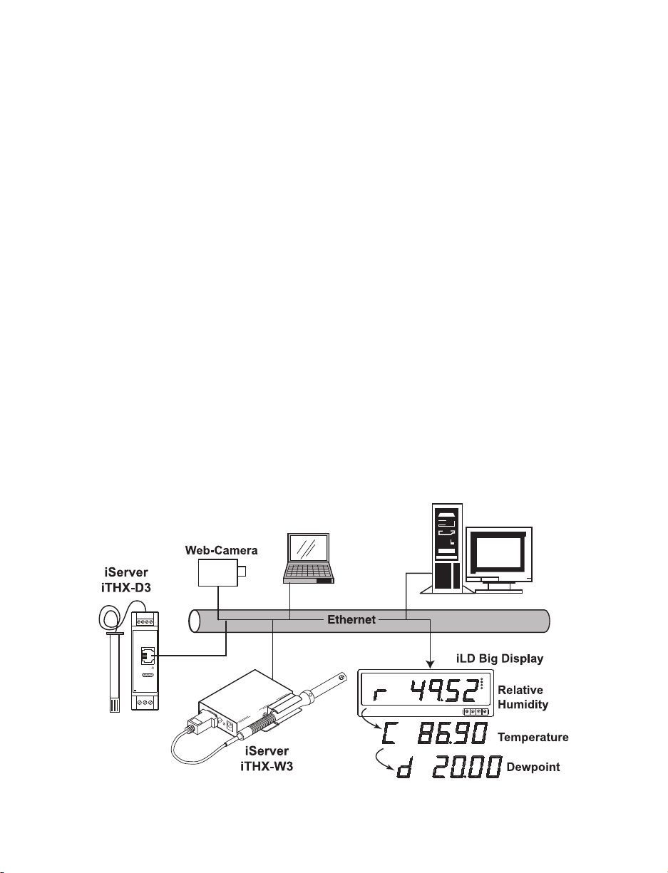
Example:
A standard web browser can be used to monitor and chart temperature and humidity.
The browser can also be used to configure the device’s IP address, passwords for
access and all configuration parameters. An iLD Big Display can display temperature
and humidity received from an iServer over the Ethernet or the Internet.
The following example illustrates how you can hookup an iServer and iLD to your
network:
Figure 1.1 iServer with Probe on the Ethernet Network
SMTP SNMP Server
COMPUTER with
Standard Web Browser
COMMUNICATIONS
ETHERNET
RESET
DC POWER IN
COL
ON
TX
RX
and
and
Page 10
PART 2 HARDWARE
2.1 Mounting
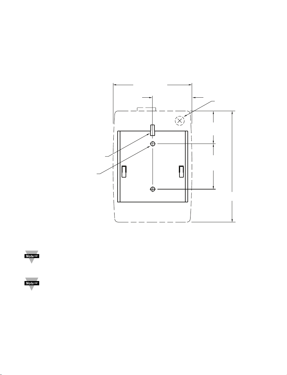
2.1.1 Mounting the Wall Mount iServer
Position unit where required. Mark and drill the two #6 screw holes.
After bracket is mounted on the wall, align back of unit over the three bracket clips, once
engaged, slide downward, the unit will snap in place.
Figure 2.1 Mounting - Wall Mount iServer
It is recommended that you ground your unit.
With one end of a wire connected to earth ground, the other side can be wraped
around the ground screw, located on the bottom of the case.
If unit is to be mounted on a flat surface, you may take the bottom rubber feet off
the unit.
4
66.0 [2.60]
33.0 [1.30]
Ethernet
Ground Screw
on Rear of Case
27.3 [1.07]
Bracket Clips (3)
38.1 [1.50]
Drill 3.6 [0.14] (2 plcs)
Use #6 Screws (Provided)
to Mount the Bracket
93.1 [3.67]
Dimensions in mm [in]
Page 11
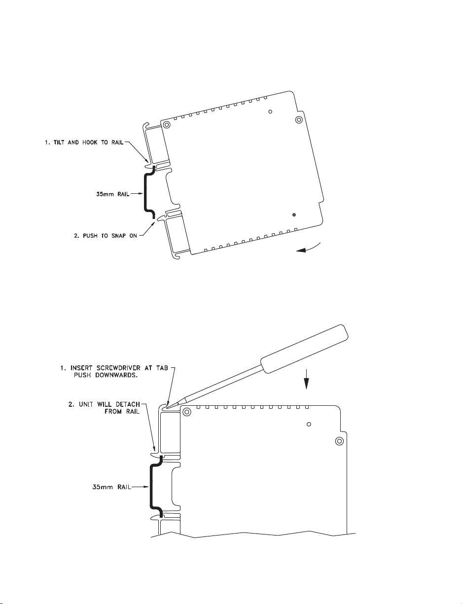
2.1.2 Mounting the DIN Rail iServer
To install unit onto DIN Rail:
a) Tilt unit, position mounting slot onto DIN Rail, as shown.
b) Push unit towards DIN Rail and it will snap into place.
Figure 2.2 Mounting - DIN Rail iServer
2.1.3 Removal from a DIN Rail
a) Insert flat screw-driver into tab and push downwards.
b) Unit will detach from DIN Rail.
Figure 2.3 Removal - DIN Rail iServer
5
Page 12
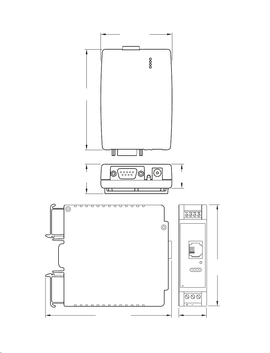
2.2 Dimensions
Figure 2.4 Mounting - Dimensions.
Figure 2.5 DIN Rail iServer Dimensions
6
66.0 [2.60]
93.1
[3.67]
27.4
[1.08]
22.4
[0.88]
COMMUNICATIONS
115 [4.53]
ETHERNET
RESET
DC POWER IN
N/C
25.1
[0.99]
90.2
[3.54]
Page 13
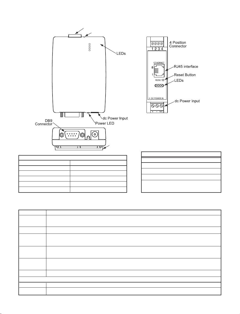
2.3 Parts of the iServer Unit
Figure 2.6 Parts of the iServer Unit
Table 2.1 Parts of iServer Unit
ETHERNET RJ45 interface for 10/100BASE-T connection.
RESET
Button: Momentary (Push and Release) resets power on unit; Push and Hold for
10 seconds to reset unit to factory defaults and reset power.
100BASE-T LED (Green) On: Indicates 100 Mbps; LED Off: Indicates 10 Mbps.
LINK/ACT LED (Green) On/Blinking: Indicates good network link and network activities
(receiving or sending packets).
DHCP LED (Yellow): When DHCP is enabled, once the iServer receives the IP
parameters from the DHCP server this LED will turn Solid yellow.
SENSOR LED (Green) On: Indiates sensor is connected and can take readings;
LED Off: the sensor in not connected
POWER LED (Green) Solid: Indicates Power-ON (for -W3 version only).
DC Power Supply Section:
+ Plus power supply wire connection (inside the plug for -W3 model).
- Minus power supply wire connection (outside the plug for -W3 model).
iTHX-D3 Connector
Pin # Channel 1
1 3.3V Red
2 RTN Black
3 SCK White
4 DATA Green
Refer to Section 2.5 for Probe details
iTHX-W3 DB9
Pin# Signal Pin# Signal
1 N/A 6 DATA CH1
2 N/A 7 SCK CH1
3 N/A 8 N/A
4 N/A 9 3.3V
5 RTN
7
TEMPERATURE
DEW POINT
HUMIDTY
1 2 3 4 5
Ethernet RJ45 interface (side)
Reset Button (side)
100BASE-T
LINK / ACT
DHCP
SENSOR
DHCP
SENSOR
LINK / ACT
100BASE-T
6 7 8 9
Mounting Bracket
Page 14
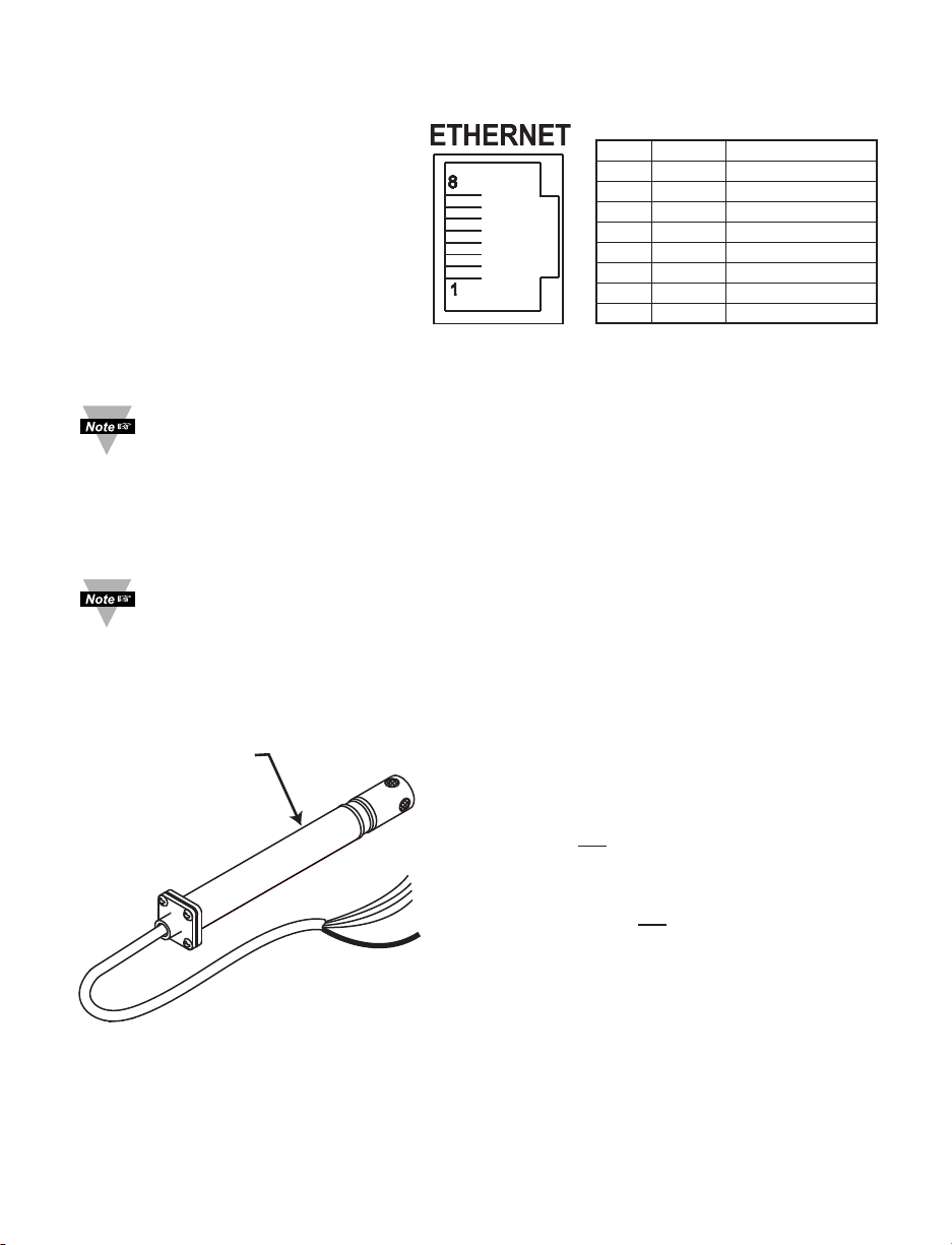
2.4 Network Communication Interfaces
2.4.1 10/100 BASE-T RJ-45 Pinout
The 10/100BASE-T Ethernet network
system is used in the iServer for
network connectivity.
The 10 Mbps or 100 Mbps twistedpair Ethernet system operates over
two pairs of wires.
One pair is used for receiving data
signals and the other pair is used for
transmitting data signals.
This means that four pins of the
eight-pin connector are used.
For CE compliance at 100 Mbps: use shielded cable, opposite end of cable must
be grounded.
2.4.2 Connecting iServer to PC/Hub/Switch/Router
The iServer’s Ethernet interface can automatically detect the Rx and Tx lines on a
twisted pair Ethernet cable (MDI/MDIX Auto Cross). Therefore, to connect an iServer to a
PC/Hub/Switch/Router, either a straight-through or a cross-over cable can be used.
On certain devices (like iServer), it is possible for the hardware to automatically
correct errors in cable selection, making the distinction between a “straightthrough” cable and a “cross-over” cable unimportant. This capability is known as
“Auto MDI/MDIX”.
2.5 Industrial Probe
Choose one which gives the best signal
integrity-
1) Connect Probe’s Shield to RTN if Probe
Housing is not
connected to Earth Ground.
OR
2) Connect Probe’s Shield to Earth Ground if
Probe Housing is not connected to Earth
Ground.
Refer to Section 2.3 for connector details.
Figure 2.8 Industrial Probe Wiring Hookup
METAL HOUSING
IS CONNECTED
TO SHIELD WIRE
Figure 2.7 RJ45 Pinout
Pin Name Description
1 +Tx + Transmit Data
2 -Tx - Transmit Data
3 +RX + Receive Data
4 N/C Not Connected
5 N/C Not Connected
6 -Rx - Receive Data
7 N/C Not Connected
8 N/C Not Connected
8
Page 15
PART 3
NETWORK CONFIGURATION
3.1 Network Protocols
The iServer can be connected to an Ethernet network communicating through standard
IP protocols including TCP, UDP, SNMP, SMTP, ARP, HTTP (WEB access), DNS, DHCP,
ICMP, SNTP, and Telnet.
3.2 Ethernet (MAC) Address
MAC (Media Access Control) address is a unique hardware number for Ethernet devices
like computers, network switches, print servers, etc. When you're connected to an
Ethernet LAN using a computer you can see a table of IP addresses called “ARP table”
stored on that computer. The ARP table relates IP addresses of devices on a network to
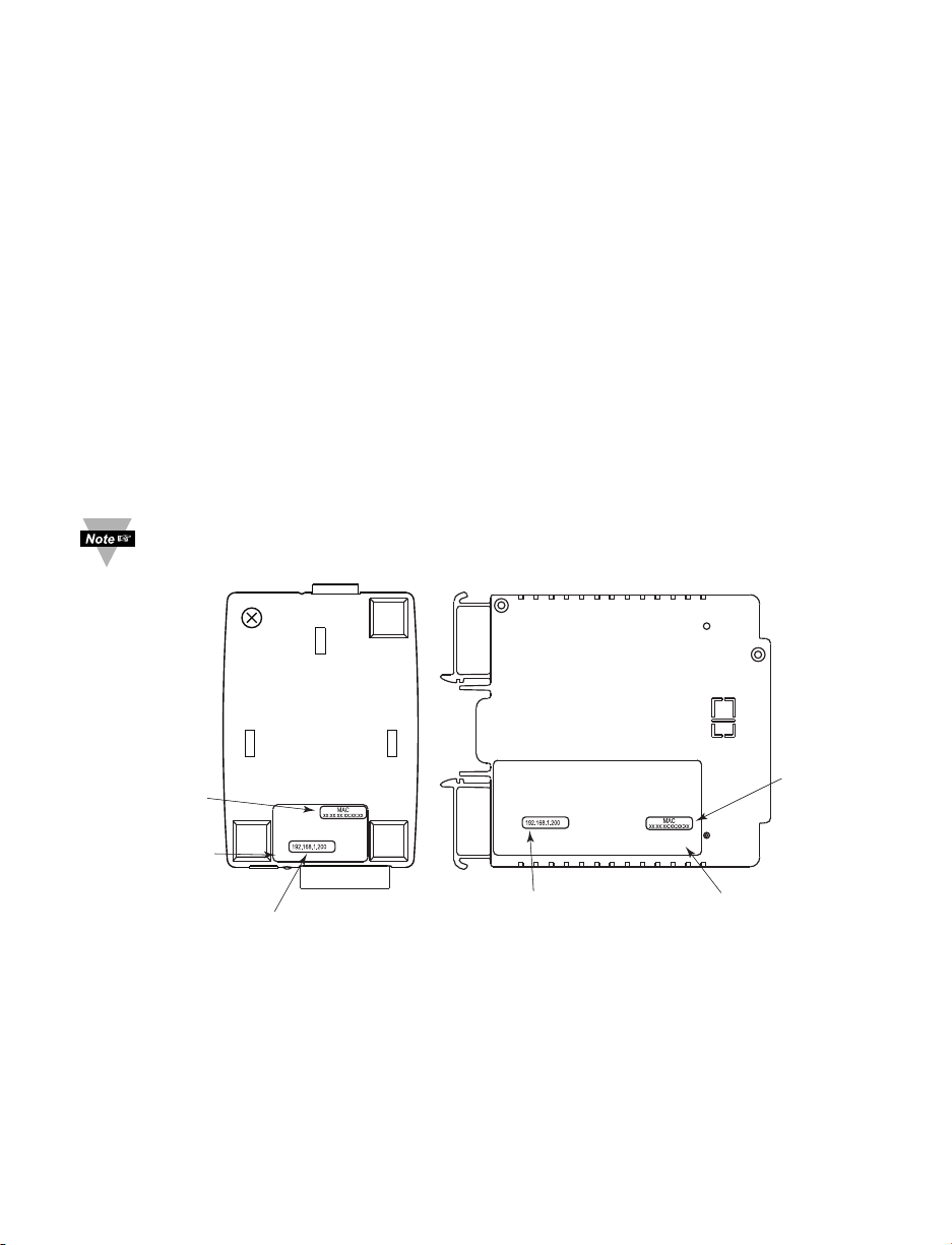
their corresponding MAC addresses. The MAC address can be found on a label
attached to your Ethernet device and it contains 6 bytes (12 characters) of hexadecimal
numbers XX:XX:XX:XX:XX:XX hex
For example: 0A:0C:3D:0B:0A:0B
Remove the small label with the default IP address and there will be room to put
your IP address. See Figure 3.1
Figure 3.1 Labeling
#.#
MODEL NO:
SERIAL NO:
INPUT POWER:
IP:
MODEL NO:
SERIAL NO:
INPUT POWER:
IP:
#.#
MAC ADDRESS
LABEL IN
HEX CODE
REMOVE DEFAULT
IP ADDRESS LABEL
AND PUT NEW
CUSTOMER'S
IP ADDRESS
iSERVER'S VERSION #
MAC ADDRESS
LABEL IN
HEX CODE
iSERVER'S VERSION #
REMOVE DEFAULT IP
ADDRESS LABEL AND PUT
NEW CUSTOMER'S
IP ADDRESS
9
Page 16

3.3 DHCP
DHCP, Dynamic Host Configuration Protocol, enables computers and network devices to
receive their IP configurations from a DHCP server.
If DHCP is enabled on your iServer, as soon as the iServer that is connected to the
network is powered on, there will be an exchange of information between the iServer and
the DHCP server. As a result, the DHCP server will assign an IP address, a Gateway
address, a Subnet Mask, and a DNS address to the iServer. Note that the DHCP server
must be correctly configured to make such assignments.
If fixed or static IP address is desired, the DHCP function must be disabled.
The iServer is shipped with DHCP disabled (factory default).
The DHCP can be enabled by accessing the iServer’s web server and selecting Network
menu (refer to Section 4.4.2).
It’s very important to communicate with the network administrator in order to
understand DHCP and its existing configurations on the host server before
enabling DHCP on the iServer.
The iServer is shipped with a default static IP address of 192.168.1.200 and
Subnet Mask of 255.255.255.0.
3.4 DNS
DNS, Domain Name System, enables computers and devices to be recognized over a
network based on a specific name instead of IP addresses.
For example, instead of having to use http://192.168.1.200 (IP address), you would use
http://ithx03ec or any name up to sixteen alphanumeric characters defined as a Host
Name in the iServer’s web server.
The default Host Name for an iServer is "ithx" followed by the last four digits of the
MAC address of that iServer unit.
On Windows servers where DHCP and DNS are separate functions it is very
important to configure the DHCP server to communicate with DNS in order for
the iServer’s Host Name to correctly respond. If you cannot access the iServer
using its Host Name, please contact your network administrator to make sure
DHCP and DNS servers are linked together.
If DNS server address is setup, all Host Names reported during weblink configuration
(i.e. SMTP server IP, SNTP server IP, SNMP trap server IP, etc.) will be translated into IP
addresses.
3.5 IP Address
Every active device connected to the TCP/IP network must have a unique IP address.
This IP address is used to build a connection to the iServer.
All network devices like computers that use TCP/IP protocol to communicate with each
other should have a unique 32-bit address called IP address. The IP address is divided
into two portions, the network ID and the host ID. For instance, every computer on the
same network uses the same network ID. At the same time, all of them have different
host IDs. For more details about the IP address see Appendix B.
101011
Page 17

3.6 Port Number
All TCP connections are defined by the IP address and a port number. A port number is
an internal address that provides a TCP/IP interface between an application software on
a computer and a device on the network or between two devices on the network.
There are two default TCP port (socket) numbers assigned to the iServer:
1) Port 2000: Once a TCP connection is made to the iServer using port 2000 or any
port number that is configured on the iServer for Local Port (see Network menu,
Section 4.4.2), the iServer can then be polled for variables like temperature,
humidity, etc. using commands. For the list of commands see Section 4.9.1.
2) Port 2002: This port is the iServer’s network console port for reading or changing
the settings within the iServer. For the list of settings refer to Section 4.8.1. For both
of the above cases, for example, a Telnet application can be used.
PART 4 OPERATIONS
Depending on user’s preference and network setup, the iServer can be configured in
several ways:
Using the latest versions of Web browsers like Internet Explorer, Firefox, Opera, or
Safari (iPhone) the iServer’s Web server can be accessed, see Section 4.2.
It can also be configured using a TCP connection to port 2002 using a command line
interface, see Section 4.8.1.
The iCONNECT Configuration Software can also be used to find and configure the
iServer over the Ethernet, see Section 4.1.2.
Before you configure the iServer, you will need to assign an IP address to the
unit. Refer to Section 4.1.1, 4.1.2 or 4.1.3.
4.1 IP Address Assignment
4.1.1 DHCP (Method 1)
The DHCP server will assign an IP address, see Section 3.3.
4.1.2 ARP HTTPget Commands (Method 2)
You can download the HTTPget program from our web site to use it for this section.
1. From the Command line (DOS prompt) where you keep the HTTPget.exe file, type the
following:
arp -s 128.100.101.76 00-03-34-00-9c-5c press the <Enter> key
128.100.101.76, for example, is the IP address that you want to assign to your iServer
and 00-03-34-00-9c-5c is the MAC address of your iServer labeled on the bottom of the
unit.
2. From the same prompt, type the following HTTPget command:
httpget -r -S “00000000” 128.100.101.76:1 press the <Enter> key
00000000 is the default ADMINISTRATOR password in your iServer unit and
128.100.101.76:1 is the IP address that your iServer will accept on TCP port 1. At this
point, you have successfully assigned 128.100.101.76 IP address to your iServer.
Continued on the following page.
Page 18
4.1.2 ARP HTTPget Commands (Method 2) (continued)
The above IP address of 128.100.101.76 is an example to show how these
commands work. To get a valid IP address on your network you need to consult
with your IT department.
Figure 4.1 shows the screen shot of an actual DOS window with the above commands
executed.
Figure 4.1 ARP and HTTPget Commands on a DOS Window
4.1.3 Direct Connection (Method 3)
The iServer is shipped with a default IP address of 192.168.1.200 and Subnet Mask of
255.255.255.0.
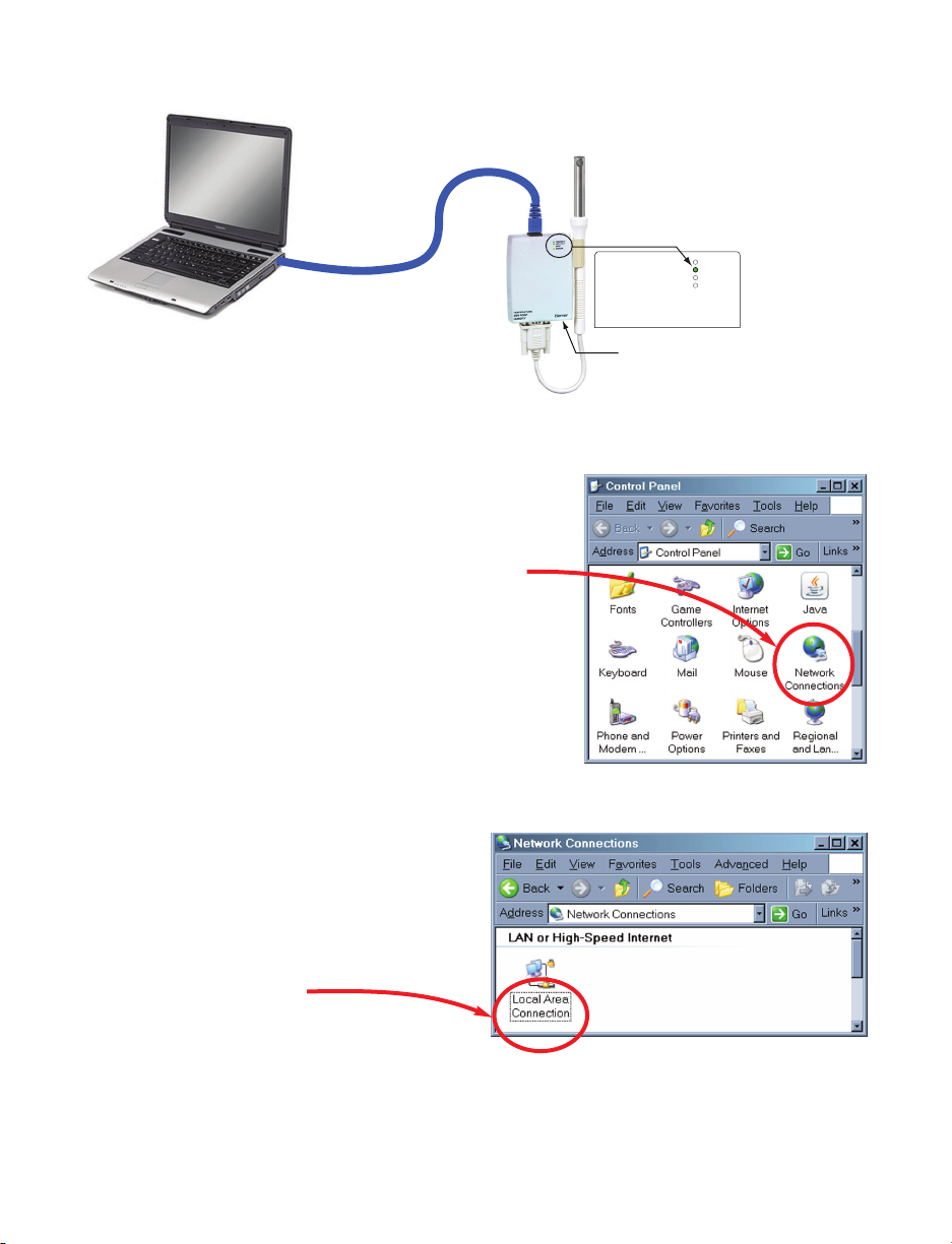
To start, connect your iServer directly to your PC using a straight or cross-over Ethernet
cable and power it on.
Make sure that the Network LINK/ACT LED on the iServer and your Ethernet switch is
solid ON. Refer to Figure 4.2.
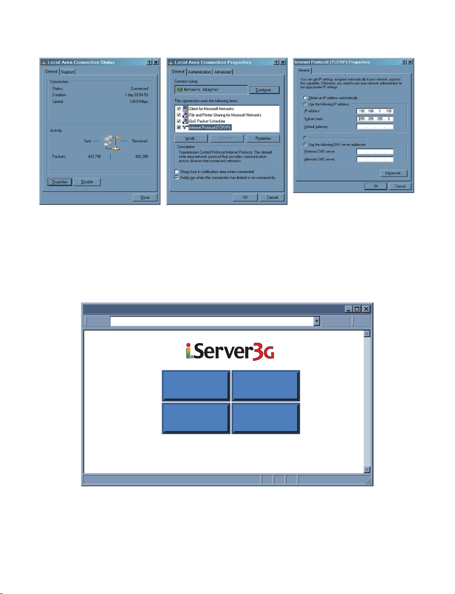
If you are going to use a Web browser or Telnet program to access the iServer using its
default IP address of 192.168.1.200, you need to make sure that the PC from which
you’re establishing the connection has an IP address that is in the same range as the
iServer’s IP address.
For example, you can assign your PC an IP address of 192.168.1.x, where x is any
number from 1 to 254.
Your PC’s IP address cannot be the same as the iServer’s IP address.
You also need to make sure that your PC’s subnet mask is 255.255.255.0.
This is a good way to access the iServer over the network and make any configuration
changes needed.
Changing your PC’s IP address is temporary and it’s only for the purpose of accessing
the iServer for initial configurations like assigning a new IP address, subnet mask, etc.
Once the iServer is configured you can put your PC back to its original IP settings.
If 192.168.1.200 is already in use on your network, connect the iServer directly to your
computer using a CAT5 Ethernet cable (either straight or cross-over cable will be detected
by the iServer) and proceed as described below.
12
C:\>arp -s 128.100.101.76 00-03-34-00-9c-5c
C:\>httpget -r -S “00000000” 128.100.101.76:1
New IP is assigned. The unit will reset in 10 seconds.
C:\>
Page 19
4.1.3 Direct Connection (Method 3) (continued)
Figure 4.2 Connecting Computer Directly to iServer
Figure 4.3 Network Connections
Figure 4.4 Local Area Connection
100 BASE-T
LINK / ACT
DHCP
SENSOR
After connecting the
iServer to computer, power it on.
LINK/ACT LED should be
SOLID green
Computer’s
Ethernet Port
(RJ45
connection)
Plug in the
Power Adapter
Ethernet Cable
iServer with
default IP address
of 192.168.1.200
1) Click on your Windows “Start” menu and select
“Control Panel” from the list options.
Double click on the “Network Connections” icon
2) You now have “Network Connections”
window opened.
The “Local Area Connection” icon has
all the settings for your ethernet
connection.
Double click on this icon.
13
Page 20
4.1.3 Direct Connection (Method 3) (continued)
Figure 4.5 Changing TCP/IP Properties on Your Computer
4) Now you may need to reboot your computer.
5) Once your PC is back up, open your browser and type the iServer’s default IP
address of 192.168.1.200 in the “Address” window of your browser and press the
Enter key.
You will soon be inside the Welcome page (see
Figure 4.6)
of the iServers WEB
server and from there you can access all the menus.
Figure 4.6 iServer Welcome Page
14
iServer3G Welcome Page
http://192.168.1.200Address
Readings Chart
Setup Web Link
Page 21

15
4.1.3 Direct Connection (Method 3) (continued)
To verify a good connection to the iServer, from a DOS prompt on your computer
type "ping 192.168.1.200" and press Enter.
You should get a reply as shown in Figure 4.7.
If you don’t receive a reply it means that you do not have a network connection
between your PC and the iServer.
Check your IP address, subnet mask, and gateway address.
Figure 4.7 Pinging the iServer from MS-DOS Prompt
C:\>ping 192.168.1.200
Pinging 192.168.1.200 with 32 bytes of data:
Reply from 192.168.1.200: bytes=32 time=15ms TTL=64
Reply from 192.168.1.200: bytes=32 time=8ms TTL=64
Reply from 192.168.1.200: bytes=32 time=8ms TTL=64
Reply from 192.168.1.200: bytes=32 time=8ms TTL=64
Pinging statistics for 192.168.1.200:
Packets: Sent=4, Received=4, Lost=0 (0% loss)
Approximate round trip times in milli-seconds:
Minimum=8ms, Maximum=15ms, Average=9ms
Page 22
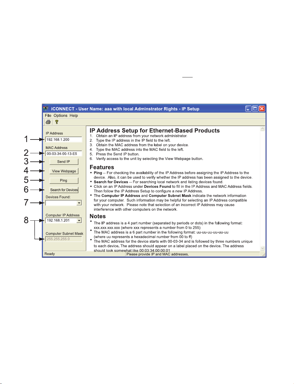
4.1.4 iConnect Software
(Method 4)
The iServer can be assigned an IP Address by using the iConnect software.
a) Download the iConnect software from the website listed on the cover of this manual
(software section).
b) Install iConnect software on a networked PC. This software is compatible with
Windows 95, 98, NT, 2000, and XP.
c) Use iConnect to assign an IP address to the iServer and access its web pages for
configuration.
You can also use any standard web browser to access the iServer’s web pages.
Consult with your IT department for obtaining an IP address.
Figure 4.8 Assigning an IP Address using iConnect
1) Place the IP address in this box.
2) Take the MAC address from the label attached to the bottom of the iServer and
place it in this box.
3) Click here to send the above IP address to the iServer.
4) After the IP address is assigned to the iServer, click here to access it’s web pages.
5) Click here to Ping the iServer whose IP address is shown in the IP address box.
6) Click here to find all the iServer’s on your network .
7) The IP addresses for the iServer’s found by the iConnect will be listed here.
8) These fields indicate the IP address and the subnet mask of the PC on which the
iConnect is running.
16
Page 23
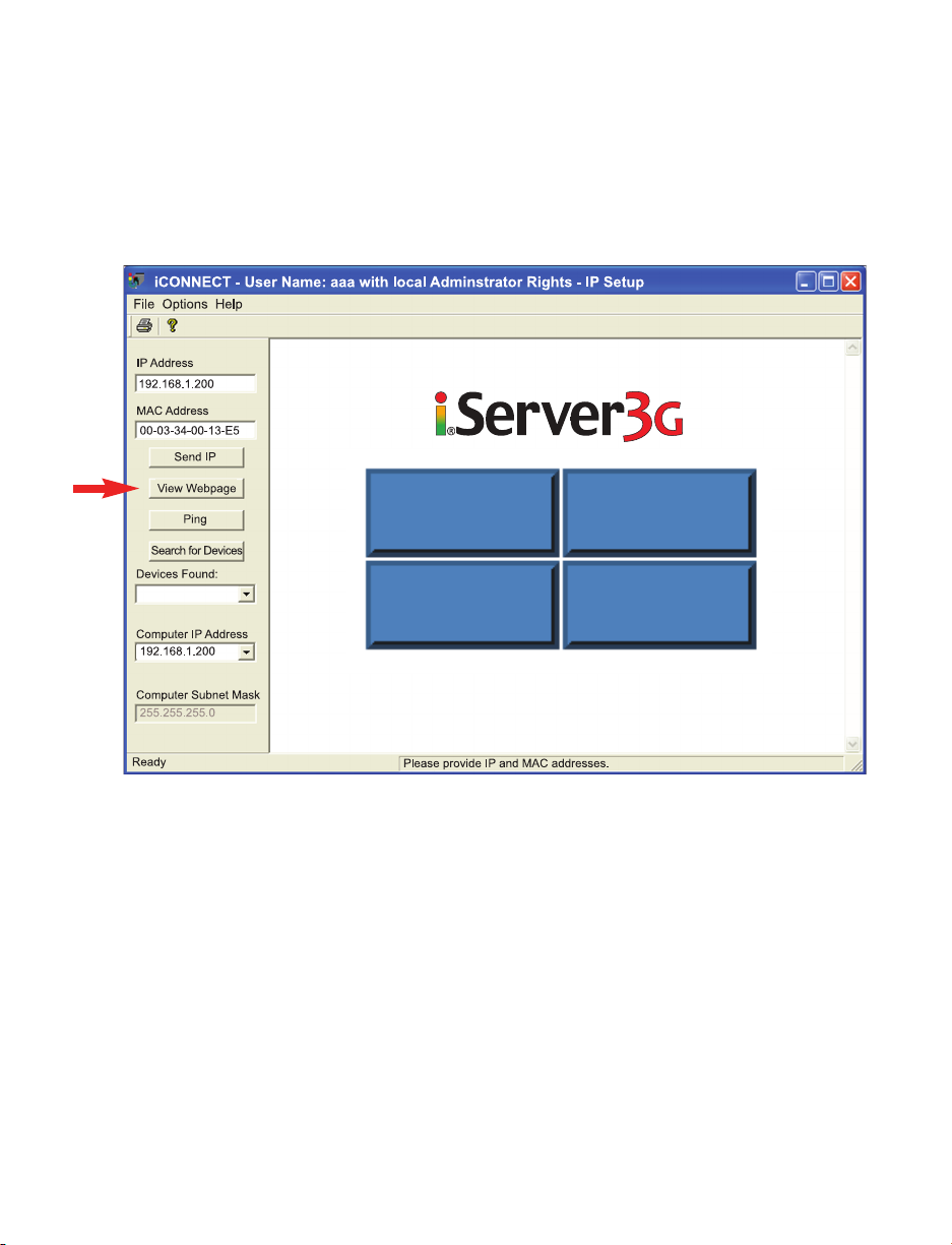
4.1.4 iConnect Software
(Method 4)
(continued)
d) To access the iServer for Configuration:
Click on the “View Webpage” button, you will access the iServer’s welcome page.
To take advantage of the iServer’s full capability use any standard web browser to
access the iServer’s web pages as described in Section 4.2.
Figure 4.9 Accessing the iServer’s using iConnect
17
Readings Chart
Setup Web Link
Page 24
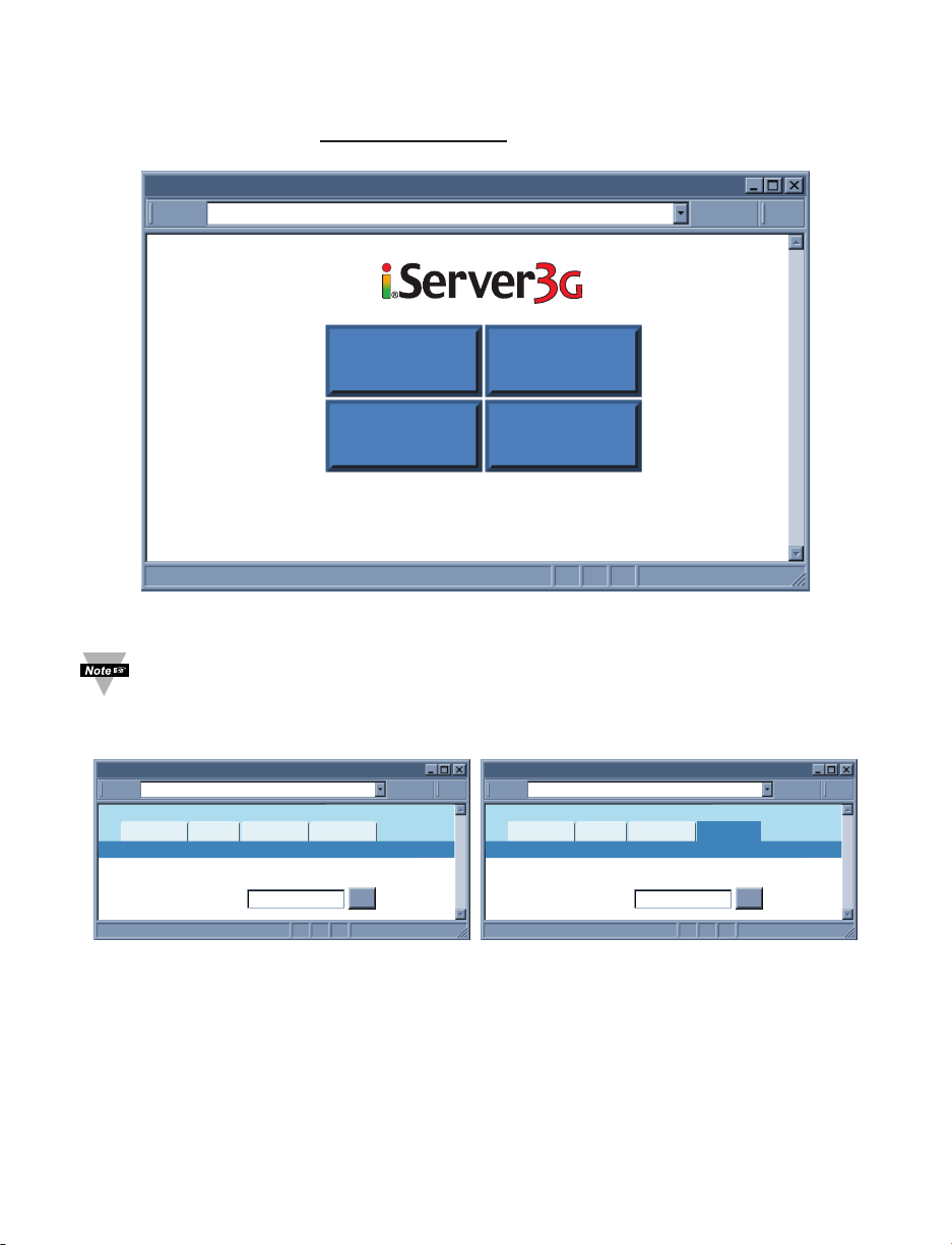
4.2 Access and Configuration Using a Web Browser
• Start your web browser.
• In the URL field, type http://192.168.1.200 (iServer’s default IP address).
• The Welcome Page, will be displayed.
Figure 4.10 iServer Welcome Page
In order to access the iServer’s web pages, users may be prompted for a
password, as shown below.
4.3 LOGIN and ADMINISTRATOR Passwords
Figure 4.11 LOGIN and ADMINISTRATOR Passwords
There are 2 different access levels:
1. LOGIN Password is required to access the iServer’s Readings, Chart, and Web Link
pages unless it’s disabled. The default password is 12345678.
2. ADMINISTRATOR Password is required to access the iServer’s Setup menu unless
it’s disabled. The default password is 00000000.
Refer to Section 4.4.5 for Password setup.
18
iServer3G Welcome Page
http://192.168.1.200Address
Readings Chart
Setup Web Link
Login
http://192.168.1.200Address
Readings
Chart
Password:
Web Link Setup
LOGIN
OK
Administrator Login
http://192.168.1.200Address
Readings
Web Link Setup
Chart
ADMINISTRATOR
Password:
OK
Page 25
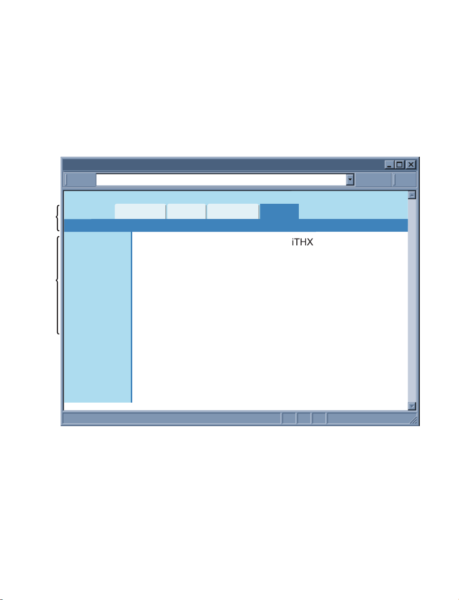
4.4 Setup
Clicking the Setup button on the Welcome page (see Figure 4.10) will provide access to
the Menu Panel (see Figure 4.12).
Using this Panel you can configure the iServer entirely.
4.4.1 Overview
Once the Administrator password is entered, the Overview page will appear which
provides a summary of important parameters within the iServer.
All the fields are read-only.
Figure 4.12 Overview
19
Overview
http://192.168.1.200Address
Menu BarMenu Panel
Overview
Network
Configuration
Management
Security
System
Diagnostics
Log Out
Readings
Model
Firmware Version
DHCP
MAC Address
IP Address
Subnet Mask
Gateway Address
Hostname
Ethernet Port
Web Server Port
Uptime
Chart
Web Link Setup
x.x
Disabled
00:03:34:00:b8:70
192.168.1.200
255.255.255.0
0.0.0.0
ithxb870
Auto
80
1 day, 00:00:00 hh:mm:ss
Page 26
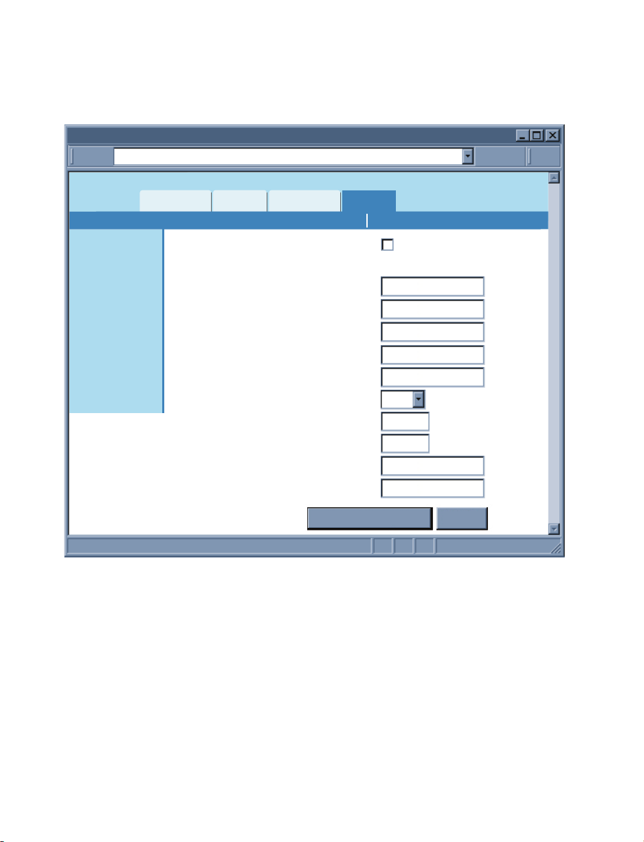
4.4.2 Network
This menu provides network configurations including IP parameters and Ethernet
interface options. Fields are described below.
4.4.2.1 IP Configuration
Figure 4.13 Network: IP Configuration
DHCP – If the box is checked the iServer will dynamically request an IP address, a
subnet mask, a gateway address, and a DNS address from the DHCP server. By default
the DHCP option is disabled. For more information about DHCP, see Section 3.3.
MAC Address – This Indicates the hardware address of the iServer and it is nonconfigurable. For more information about MAC Address, see Section 3.2.
IP Address – This indicates the IP address of the iServer. The iServer’s default IP
address is 192.168.1.200. When DHCP is enabled this field will be dimmed. Consult with
your IT department for obtaining an IP address.
Subnet Mask – It’s a 32-bit number that is used to determine which part of the IP
address is the network portion and which part is the host portion. When DHCP is enabled
this field will be dimmed. The iServer’s default Subnet Mask is 255.255.255.0. Consult
with your IT department for obtaining a subnet mask.
20
IP Configuration
http://192.168.1.200Address
Readings
Overview
Network
Configuration
Management
Security
System
Diagnostics
Log Out
Chart
DHCP
MAC Address
IP Address
Subnet Mask
Gateway Address
DNS Address
Host Name
Protocol
Local Port
Web Server Port
Web Link Title
Web Link Address
Web Link Setup
IP Configuration Ethernet Port
00:03:34:00:b8:70
192.168.1.200
255.255.255.0
0.0.0.0
0.0.0.0
ithxb870
TCP
2000
80
WebLink
0.0.0.0
Save Changes Reset
Page 27

21
4.4.2.1 IP Configuration (continued)
Gateway Address – This points to the router that forwards traffic to a destination
address outside of the subnet on which the iServer resides. This is the IP address of the
router which functions as a gateway. When DHCP is enabled this field will be dimmed.
The iServer’s default Gateway address is 0.0.0.0. Consult with your IT department for
obtaining a gateway address.
DNS Address – In order to use the hostname to access the iServer, the DNS server on
your network must be configured, refer to Section 3.4. iServer plays the role of a DNS
client, in the sense that the iServer will actively query the DNS server for the IP address
associated with a particular domain name. When DHCP is enabled this field will be
dimmed. The iServer’s default DNS address is 0.0.0.0. Consult with your IT department
for obtaining a DNS address.
Host Name – If DHCP is enabled, the iServer will send this name to the DHCP server.
This name is used so that the iServer can be accessed based on a specific name
instead of an IP address. For example, instead of using http://192.168.1.200
(IP address), you would use http://ithxA838 or any name up to sixteen (16)
alphanumeric characters. The default Host Name for an iServer is "ithx" followed by the
last four digits of the MAC address of that particular iServer.
On Windows servers where DHCP and DNS are separate functions it’s very
important to configure the DHCP server to communicate with DNS in order for
the iServer’s Host Name to correctly respond. If you cannot access the iServer
using its Host Name, please contact your network administrator to make sure
DHCP and DNS servers are linked together.
Protocol – It’s the network protocol the iServer communicates with the Ethernet
Network. Options are TCP and UDP. The default is TCP.
Local Port – The default port is 2000. Refer to Section 3.6.
Web Server Port – The default port is 80. This is the primary port number for the HTTP
protocol used for communication between internet browsers and web sites/web servers.
Web servers open this port then listen for incoming connections from web browsers.
Similarly, when a web browser is given an IP address (like the iServer’s IP address), it
assumes that the iServer’s web server is listening for connections on port 80. If this port
is changed to anything but 80 then on the browser the new port number must be
indicated with a colon (:) after the IP address. For example, if the Web Server Port is
changed to 500, you will then need to type http://192.168.1.200:500 on the browser to
access the iServer’s web server.
One of the applications where the Web Server Port number may need to change
is when users want to access the iServer’s web server from outside the local
area network (i.e. Internet). By setting up “Port Forwarding” inside a router that
is the gateway to that local area network this task can be accomplished. “Port
Forwarding” technique uses the Web Server Port number to forward the Internet
connection to the iServer on the LAN.
Web Link Title – This is a text field that appears on the button on the iServer’s Web Link
Page, refer to Section 4.7. This can describe the Web Link Address assigned below.
Web Link Address – This provides a network link to any IP device on that network. If
your IP device has a web server (just like the iServer) then you can access it directly
from the same browser you accessed the iServer. Simply, click on the Web Link button
on the iServer’s welcome page.
Page 28
22
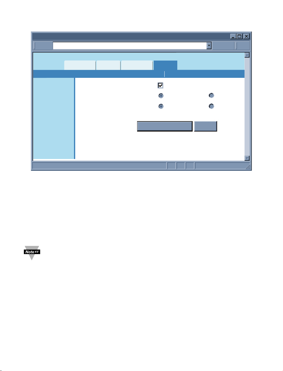
4.4.2.2 Ethernet Port
Figure 4.14 Network: Ethernet Configuration
Auto-Negotiation – It is the link, in terms of speed and duplex, between the iServer and
another Ethernet device like an Ethernet switch.
If Auto-Negotiation box is checked, the iServer will auto-negotiate the speed and duplex
with the attached Ethernet device. If any of the other options are selected, the speed
and duplex will be fixed.
It’s important to have the same Ethernet port configuration on the iServer and the
attached Ethernet device. If iServer cannot auto-negotiate with the attached Ethernet
node it will default to 10 Mbps and Half-Duplex. Once Auto-Negotiation is checked, other
fields under this category will be dimmed. By default the Auto-Negotiation is checked.
If the iServer detects the link to be 100 Mbps the 100 BASE-T LED will be solid
green.
4.4.3 Configuration
This menu provides configurations for the real-time clock, server parameters, sensors,
and alarm relays settings. Fields are described below.
4.4.3.1 Date and Time
Current Date – This field indicates the iServer’s real time clock date. The format is
yyyy/mm/dd. When there is no date defined, the iServer will be defaulted to 2099/01/01
and be shown in red to alert you that it has not yet been set.
Current Time – This field indicates the iServer’s real time clock time. The format is
military time (24-hour) and it is entered as hh:mm:ss.
Change Date and Time – By clicking on this option the real data and time can be entered.
Ethernet Port
http://192.168.1.200Address
Overview
Network
Configuration
Management
Readings
Auto-Negotiation
Speed
Duplex
Chart
Web Link Setup
IP Configuration Ethernet Port
100 Mbps
Full
10 Mbps
Half
Security
System
Diagnostics
Save Changes Reset
Log Out
Page 29
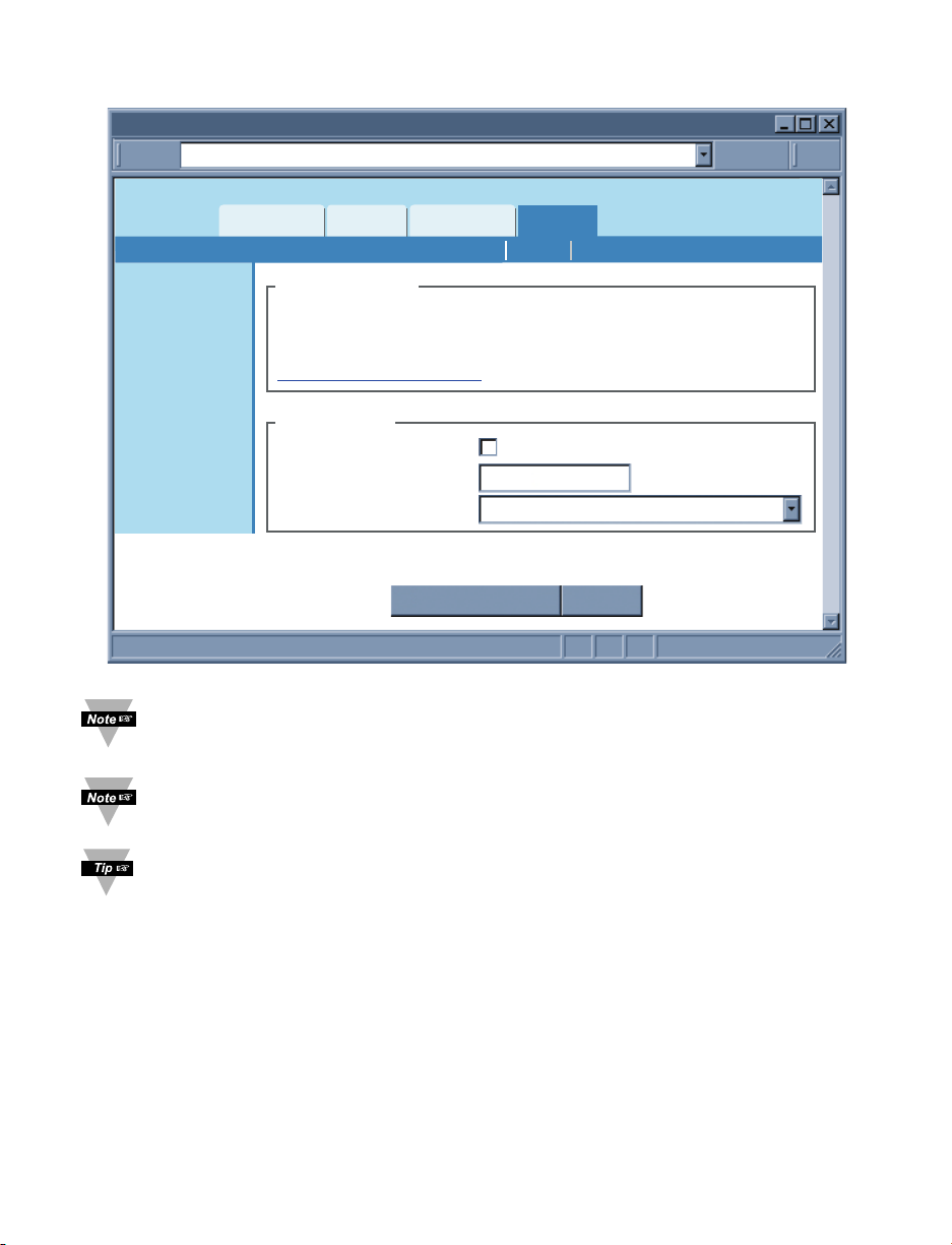
4.4.3.1 Data and Time (continued)
Figure 4.15 Network: Ethernet Configuration
Once the AC adaptor is disconnected from the iServer, the iServer will lose its
date and time settings.
Once the iServer is rebooted from any web page, the iServer will lose its date
and time settings.
If the iServer is setup to get it’s time from a Network Time Server, then the time
will be re-assigned after the reboot.
Network Time Server – If there is a time server on the network or the Internet, the
iServer will get the real date and time once the Network Time Server’s IP address is
provided. Default is unchecked.
NTS Address – The field to enter the Network Time Server’s IP address.
The U.S. National Institute of Standards and Technology (NIST) publishes a list of time
servers on the Internet used by the NIST Internet Time Service (ITS). The list includes
each server’s name, IP address, and location in the United States. As of the publication
date of this manual, links to the list can be found at http://tf.nist.gov.
Time Zone – If Network Time Server option is checked, the correct time zone must be
selected for the correct time display.
23
Date and Time
http://192.168.1.200Address
Readings
Overview
Network
Configuration
Management
Security
System
Diagnostics
Log Out
Chart
Date and Time
Current Date
Current Time
Change Date and
Time Server
Network Time Server
Web Link Setup
SensorsServerDate and Time
2099/01/01 (yyyy/mm/dd)
00:00:00
Time
NTS Address
Time Zone
(GMT-08:00)Pacific Time(US&Canada)
Save Changes Cancel
Page 30
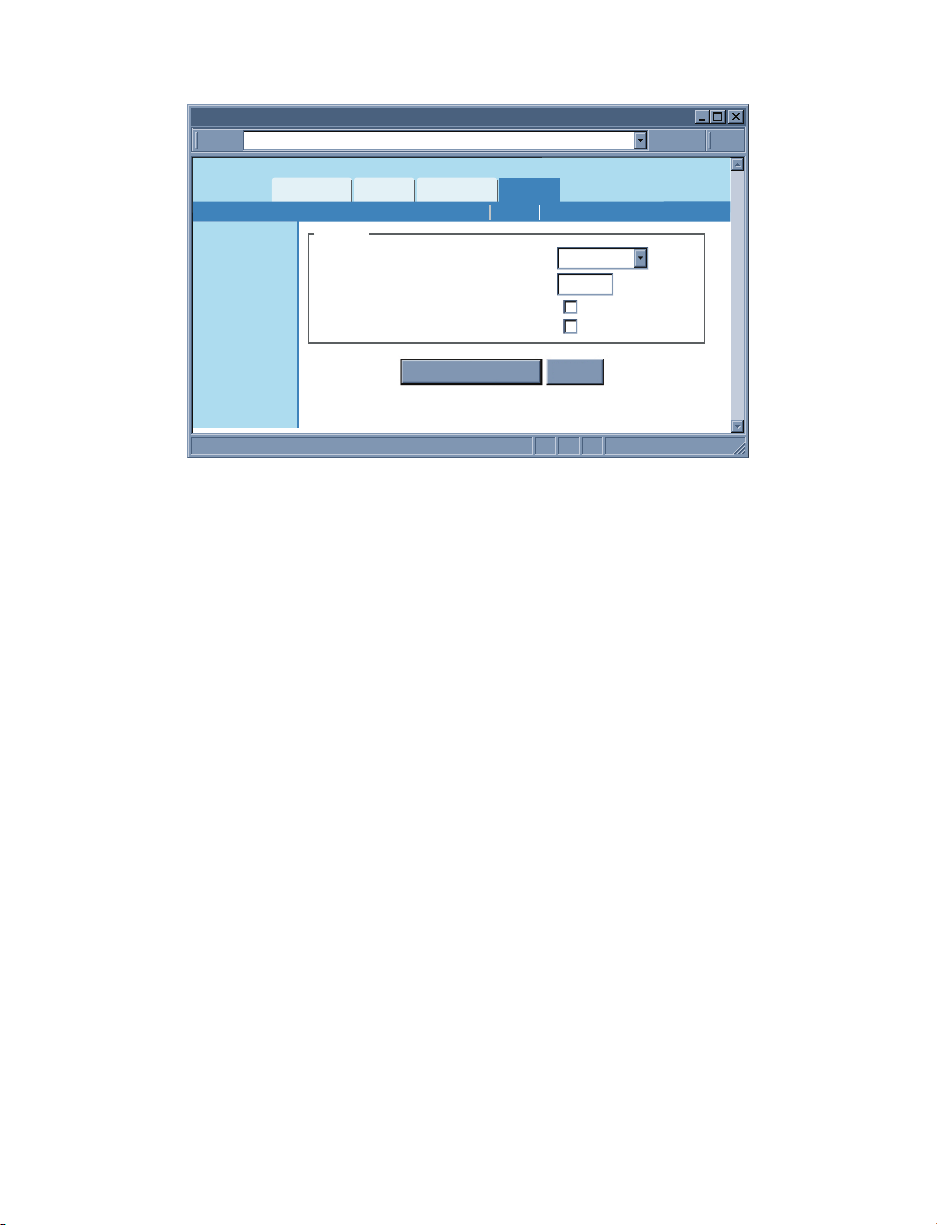
24
4.4.3.2 Server
Figure 4.16 Configuration Menu: Server
Server Type – Options are Command and Continuous.
If Command is selected the iServer will respond to commands sent from a network host
(for the list of commands refer to Section 4.9.1).
If Continuous is selected the iServer will send temperature, humidity, dewpoint values
and alarm relay status once every time amount selected in the Interval box.
The Command and Continuous modes operate when a network host opens a TCP
connection to the iServer’s IP address with port 2000.
In UDP Command mode, iServer will respond back with a UDP packet (to the _ address and
port) if a host application sends a UDP command to iServer’s IP address with port 2000.
In UDP Continuous mode, iServer starts sending continuous data if a host application
sends a trigger or UDP packet to iServer’s IP address with port 2000.
Interval – This is the time interval (in seconds) between each data transmission when
the iServer is in Continuous mode. The default value is set to 5 seconds and the
minimum is 2 seconds.
Time Stamp – If checked, the iServer will stamp the data with date and time before
sending it out to a network host. This will apply to Command and Continuous modes.
Default is unchecked.
Disconnect After Data Sent – If checked, once the iServer responds back with data, the
iServer will close the TCP connection that had been made from the network host.
This feature should be used if data acquisition software expects data to be ended by
closing TCP connection from the client.
4.4.3.3 Sensors
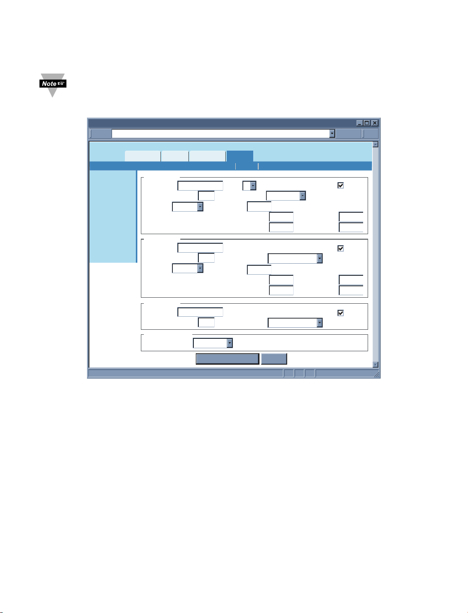
This is the page where the Sensor Parameters are defined. Reading 1 is for
Temperature, Reading 2 is for Humidity, and Reading 3 is for Dewpoint.
Description – This can be a name for the sensor or where the sensor is located. This
field is text only and can have up to 16 alphanumeric characters. This description will
appear wherever Reading 1, 2 or 3 is displayed on the web server.
Server
http://192.168.1.200Address
Overview
Network
Configuration
Management
Security
System
Diagnostics
Log Out
Readings
Chart
Server
Server Type
Interval
Time Stamp
Disconnect After Data Sent
Web Link Setup
SensorsServerDate and Time
Command
5 seconds
Save Changes Reset
Page 31
25
4.4.3.3 Sensors (continued)
Unit – This would be the units of measurement for that particular sensor. Examples are
% for humidity, F and C for temperature and dewpoint.
Once the unit of temperature is selected, either C or F, it will be a global change
through out the web server, as well as on the LCD display.
Figure 4.17 Configuration Menu: Sensors
Display – If checked the variable (i.e. temperature) will be displayed on the Readings
and Chart applets as well as data transmission in Continuous mode (see Server Section
4.4.3.2). The default is checked.
End Character – This means that the iServer will send a character (in Hex) after the
value for each variable. This will apply to either Continuous or Command mode. The
default is set for 0D (Hex representation of <CR>).
Data Format – This indicates the format of the variable being displayed on a network
host when Continuous or Command transmission is used. Reading 1: T000.0C, 000.0C,
000.0; Reading 2: H00.0%, 00.0%, 00.0 (the C or F will change to the appropriate unit
once you press Save Changes button).
Adjust by – If it’s determined that the reading is slightly off this field can be used to
adjust the reading. The options are Offset and Scale & Offset.
Using the Offset method you can manually assign a numerical value to adjust the
reading. For example if the actual reading is 55 where it should be 54 you can enter -1 in
the Offset field.
Sensors
http://192.168.1.200Address
Overview
Network
Configuration
Management
Security
System
Diagnostics
Log Out
Readings
Reading 1
Description
End Character
Adjust by
Reading 2
Description
End Character
Adjust by
Reading 3
Description
End Character
Sampling Rate
One Sample per
Chart
Temperature
Offset
Humidity
Offset
Dewpoint
Web Link Setup
Unit Display
0x
0x
0x
10 seconds
Data Format
0D
Offset
Reading Low
Reading High
Unit %
0D
Data Format
Offset
Reading Low
Reading High
Unit C
0D
Data Format
Save Changes Reset
SensorsServerDate and Time
C
000.0C
0.0
0.0
0.0
100.0
H00.0%
0.0
100.0
D000.0C
Ref. Low
Ref. High
Display
Ref. Low
Ref. High
Display
0.0
100.0
0.0
100.0
Page 32
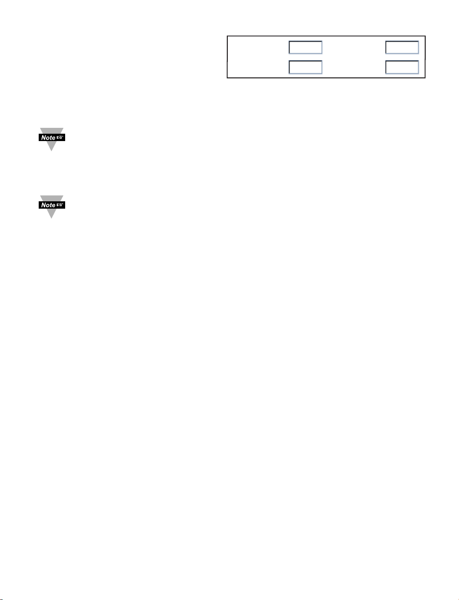
4.4.3.3 Sensors (continued)
The Scale & Offset method uses two
points to adjust the reading within the
entire temperature range. For example,
if at the lower point the actual reading is
10 where it should be 12 and at the higher point the actual reading is 200 where it should
195, here is how the numbers are entered.
The adjusting numbers can be positive or negative with one decimal point.
The adjusting values must be assigned after the unit of temperature (C or F) is
selected. If the unit of temperature is changed, you must readjust the values for
a correct result.
Offset – If it’s determined that the reading is slightly off, this field can be used to
manually assign a numerical value to adjust the reading. The offset can be a positive or
a negative number with one decimal point.
The temperature offset value must be assigned after the Unit (C or F) is
selected. If the unit of temperature is changed, you must reassign the offset
value for the correct result.
Sampling Rate – This determines the rate in which the iServer polls the probe for
temperature and humidity values. The options are 1, 10, and 60 seconds.
The default is set for 10 seconds.
4.4.4 Management
This page provides the iServer’s email, SNMP and alarm settings. SNMP (Simple
Network Management Protocol) is the protocol used by network management systems to
communicate with network devices that respond to SNMP connections for the purpose of
problem detections and corrections.
If SNMP and/or SMTP features are desired, please make sure iServer’s network setting
as well as SNMP trap server and SMTP mail server are setup properly. Failure to do so
may cause iServer to be unresponsive while waiting for these servers to reply back.
4.4.4.1 Setup
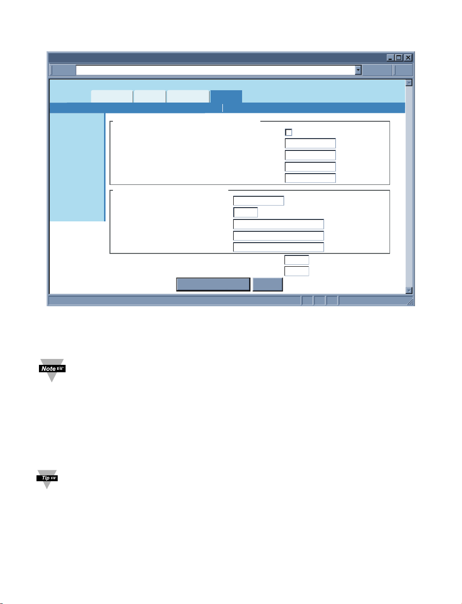
Simple Network Management Protocol
SNMP Response Enabled – If this option is checked the iServer will respond to network
nodes broadcasting SNMP requests. The default is unchecked.
Make sure your network is setup properly (gateway, etc) before using SNMP feature
SNMP Community – Every SNMP communication takes place using a community
string. The default is Public.
Contact – This text field specifies the contact person for this node, together with information on
how to contact this person. This field takes up to 16 alphanumeric characters.
Location – This text field specifies the location of the iServer. For example it can be
“control station”, which is the place where the iServer is located. This field takes up to 16
alphanumeric characters.
SNMP Trap Server – This field contains the IP address of the SNMP trap server located
somewhere on the network. The trap server listens for SNMP traps coming from the
iServer when there is an alarm condition (refer to Alarms Section 4.4.4.2 under the
Management page).
26
Reading Low 10.0
Reading High
200.0
Ref. Low
Ref. High
12.0
195.0
Page 33
4.4.4.1 Setup (continued)
Figure 4.18 Management Menu: Setup
Simple Mail Transfer Protocol
SMTP Server – This field specifies the IP Address of the SMTP server.
1) You must have an email server (SMTP server) on your network in order to
receive emails generated by the iServer.
2) iServer does not support SMTP server authentication.
SMTP Server Port – This specifies the TCP port used by the SMTP Server. The default is 25.
From – This field specifies the name of the person who sends the email. It can also be
an email address.
To – This field specifies the email address of the recipient. This field can take up to 200
alphanumeric characters; limited to 4 addresses of 50 characters each. Each address
should be separated by a comma, without spaces. Ex: [email protected],[email protected]
You can create a “distribution group address” if you need to have more email
addresses.
27
Setup
http://192.168.1.200Address
Readings
Overview
Network
Configuration
Management
Security
System
Diagnostics
Log Out
Chart
Simple Network Management Protocol
SNMP Response Enabled
SNMP Community
Contact
Location
SNMP Trap Server
Simple Mail Transfer Protocol
SMTP Server
SMTP Server Port
From:
To:
Subject:
Reminder Interval
Transmission Delay
Web Link Setup
AlarmsSetup
0.0.0.0
25
Save Changes Reset
public
None
None
0.0.0.0
60
1
mins
mins
Page 34

4.4.4.1 Setup (continued)
Subject – This field specifies the subject of the email. Emails for all the alarms will have
this common subject line. Example of a subject can be “Alarm from iServer”.
Reminder Interval – This field sets a reminder interval for email and/or trap to be sent
again. The allowed minimum value is 1 minute. If it’s set to 0 the iServer will not send a
reminder email. The default is 60 minutes.
Power Reset alarm is only sent once, regardless of reminder interval.
Transmission Delay – Once the iServer alarm condition is met, this is the amount of
time the alarm condition is met before iServer sends any email or trap. If it’s set to 0,
email and/or trap will be sent immediately. The default is 1 minute.
4.4.4.1.1 Sending Text Messages to a Cell Phone
In the SMTP To field, you can use the following format to have the iServer send a text
message to your cell phone. Since most cell phones are capable of receiving text
messages you just need to find the correct email format for your cell phone provider.
T-Mobile [email protected]
Virgin Mobile [email protected]
AT&T [email protected]
Sprint [email protected]
Verizon [email protected]
Nextel [email protected]
“phone_number” is your 10 digit cell phone number.
28
Page 35
29
4.4.4.2 Alarms
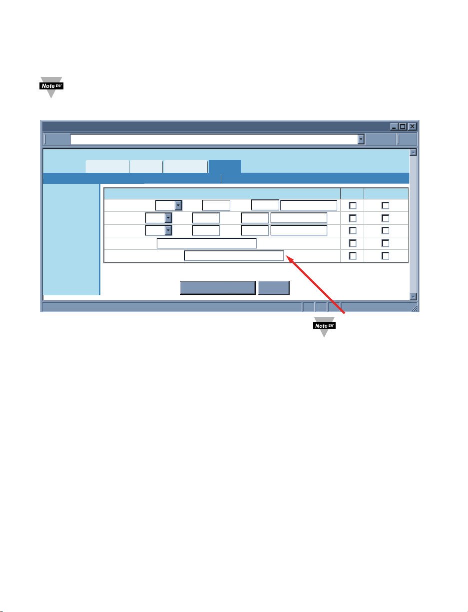
This includes events or conditions. Once a condition is met the iServer will send an email
or/and an SNMP trap if either one or both are checked. Fields are described below.
Multiple alarm events can be checked and for each event an email and/or a trap
will be sent.
Figure 4.19 Management Menu: Alarms
Temperature – The options are Low, High, and Low or High.
If Low is selected the Low field must be given a value (lower than that value is an alarm
condition).
If High is selected the High field must be given a value (higher than that value is an
alarm condition).
If Low or High is selected the Low and High fields must be given values (outside the
band is an alarm condition).
Humidity – The same as Temperature defined above.
Dew Point – The same as Temperature defined above.
Power Reset – This refers to the iServer being powered off and back on (power reset).If
the option is checked the iServer will automatically send one email or/and an SNMP trap
after rebooting, regardless of reminder interval.
Probe Disconnected – If the probe attached to the iServer is disconnected that is
considered as an alarm condition.
http://192.168.1.200Address
Alarms
Readings
Chart
Web Link Setup
Overview
Network
Configuration
Management
Security
System
Diagnostics
Log Out
Save Changes Reset
Temperature Low Low 0.0 High 0.0Low 0.0 0.0
Low High
Low 0.0 0.0
Low HighLow 0.0 0.0
Humidity
Dewpoint
Power Reset
Probe Disconnected
Events
Email SNMP Trap
AlarmsSetup
There is text box next
to each event. The
text content will be
the body of the email.
Page 36
30
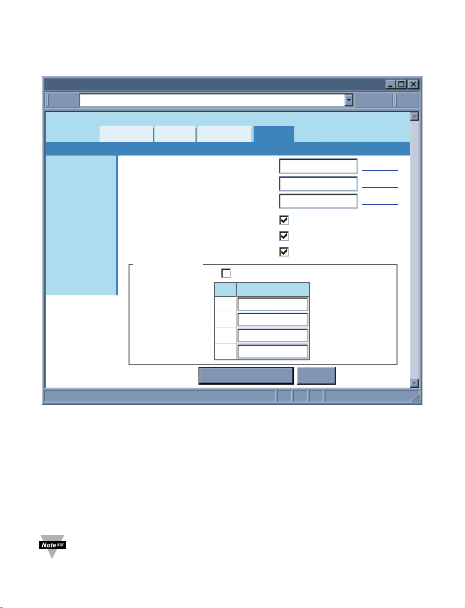
4.4.5 Security
This page provides security and access settings for the iServer. Fields are described
below.
Figure 4.20 Security Menu
Login Password – To access Readings, Chart, and Web Link menus this password is
required. The password length can be up to 16 alphanumeric case-sensitive characters.
To change the password click on Change.
Empty box means no password is required. The default Login Password is 12345678.
Administrator Password – To access Setup menu this password is required. The
password length can be up to 16 alphanumeric case-sensitive characters. To change the
password click on Change.
Empty box means no password is required. The default Administrator Password is
00000000.
This password will also be prompted when Telnet connection to port 2002 is
made. Port 2002 is the Telnet console port that allows users to configure some
of the parameters that can be configured through the web server.
http://192.168.1.200Address
Security
Readings
Chart
Web Link Setup
Overview
Network
Configuration
Management
Security
System
Diagnostics
Log Out
Save Changes Reset
Login Password
Admin Password
Local Port Password
Telnet Console Access
Web Server Access
Secured Readings and Charts
Change
Change
Change
IP Exclusivity
12345678
00000000
1
2
3
4
0.0.0.0
0.0.0.0
0.0.0.0
0.0.0.0
Enable
No
IP Address
Page 37
4.4.5 Security (continued)
Local Port Password – To access the iServer via TCP or UDP socket connection to
port 2000, this password is required. The maximum length can be up to 16
alphanumeric case-sensitive characters.
Empty box means no password is required. The default is none.
Telnet Console Access – If it is unchecked, Telnet console connection to port 2002 will
be blocked. The iServer must be rebooted for the change to take place.
The default is checked.
Web Server Access – If it is unchecked, the iServer’s Web server will not be accessible.
The iServer must be rebooted for the change to take place.
The default is checked.
When the Web Server Access is not enabled, the iServer needs to be
configured using Telnet console.
If someone needs to access the Web Server again, use the Telnet console to
enable it.
Secured Readings and Charts – If it is checked the Login password will be required to
display Readings and Chart applets.
The default is checked.
IP Exclusivity – This table contains the IP addresses that are allowed to communicate
with the iServer over TCP or UDP connection. This means if the table is empty
connections from all IP nodes are allowed to the iServer.
If enabled, all packets from IP addresses not on this list are ignored and thrown away.
4.4.6 System
This menu provides various options to reboot, restore defaults, upgrade firmware and
download/upload configuration for the iServer. Fields are described below.
4.4.6.1 Reboot
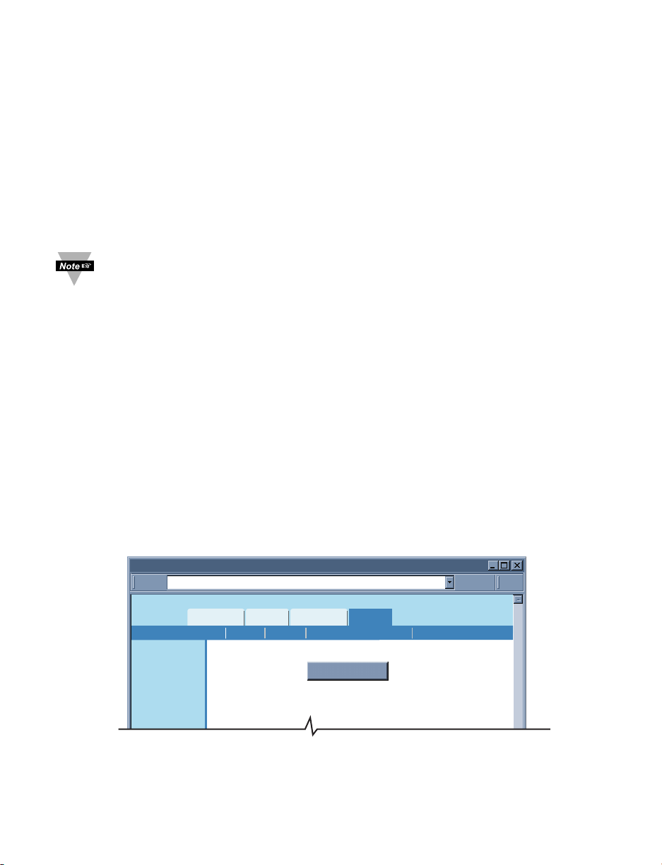
Figure 4.21 System: Reboot
Reboot – This option resets the power on the iServer.
It will set the real date/time back to default unless the Network Time Server option from
Configuration page, is enabled.
http://192.168.1.200Address
Reboot
Readings
Chart
Web Link Setup
Overview
Network
Configuration
Management
Security
System
Reboot
DefaultsReboot Download ConfigurationUpgrade Upload Configuration
31
Page 38
3232
4.4.6.2 Defaults
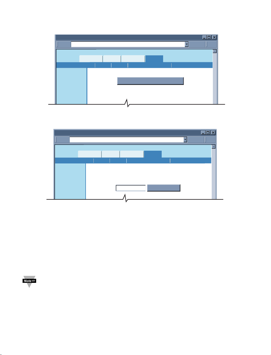
Clicking on this button will put the iServer back to its default settings.
Figure 4.22 System: Defaults
4.4.6.3 Upgrade
Figure 4.23 System: Upgrade
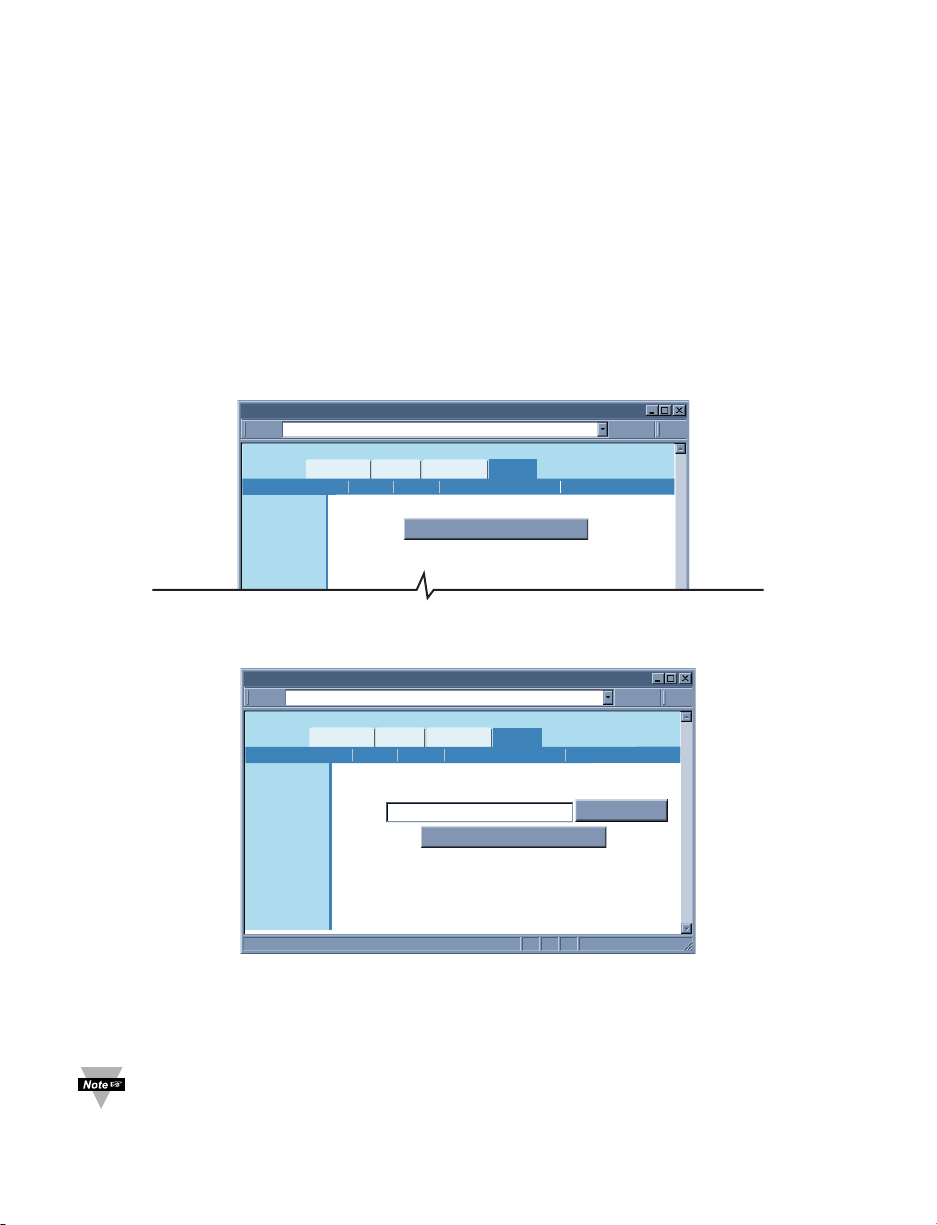
Upgrade – This option loads a new firmware into the iServer over the network. The
firmware is a binary file with .bin extension.
Before proceeding with the firmware upgrade, enter the name of the file you plan to use,
click on Check File Name button.
If OK, a new screen will appear and you can then browse to the actual upgrade firmware
file “iTHX_x.bin” and click on the Upload button.
After the file has upgraded the iServer will automatically reboot and load the new
firmwar, you will be returned to the Welcome page.
After you have successfully upgraded your device, you can verify the firmware
version number on the “Overview” page (see Section 4.4.1).
It’s recommended to set the iServer to default settings after the firmware is upgraded.
See above Section 4.4.6.2 on how to set the iServer to default settings.
Applying default settings will change the iServer’s settings to factory defaults.
http://192.168.1.200Address
Defaults
Readings
Chart
Web Link Setup
Overview
Network
Configuration
Management
Security
System
Restore Factory Defaults
DefaultsReboot Download ConfigurationUpgrade Upload Configuration
http://192.168.1.200Address
Upgrade
Readings
Chart
Web Link Setup
Overview
Network
Configuration
Management
Security
System
DefaultsReboot Download ConfigurationUpgrade Upload Configuration
Before proceeding with firmware upgrade, enter the name
of the file that you have for firmware upgrade.
Check File Name
Page 39
4.4.6.3 Upgrade (continued)
If those settings are important to you and you do not want to reconfigure the iServer, you
will need to do the following steps.
From the “System” menu:
1) “Download Configuration” the iServer’s configuration settings, Section 4.4.6.4.
2) “Upgrade” the iServer with the new firmware, Section 4.4.6.3.
3) Set the iServer to “Default” settings. The iServer’s IP address is now
192.168.1.200.
4) “Upload Configuration” the same configuration you obtained from Step 1 onto
the iServer, Section 4.4.6.5.
4.4.6.4 Download Configuration
Clicking on this button will download the configuration file that contains all the settings
stored in the iServer and use it as a reference.
Figure 4.24 System: Download Configuration
4.4.6.5 Upload Configuration
Figure 4.25 System: Upload Configuration
Upload Configuration – Using this option to upload the configuration file into the
iServer. It is recommended to download and store a working copy of this configuration
file in case the device is configured improperly.
You can set the iServer to its default settings and upload the configuration file
back into the iServer.
http://192.168.1.200Address
Download Configuration
Readings
Chart
Web Link Setup
Overview
Network
Configuration
Management
Security
System
Download Configuration File
DefaultsReboot Download ConfigurationUpgrade Upload Configuration
33
Upload Configuration
http://192.168.1.200Address
Overview
Network
Configuration
Management
Security
System
Diagnostics
Log Out
Readings
DefaultsReboot Download ConfigurationUpgrade Upload Configuration
Please make sure no other clients are connected to the device.
Web Link Setup
Chart
Upload Configuration File *.cfg
Consult manual for complete instructions.
Browse...
Page 40
34
4.4.7 Diagnostics
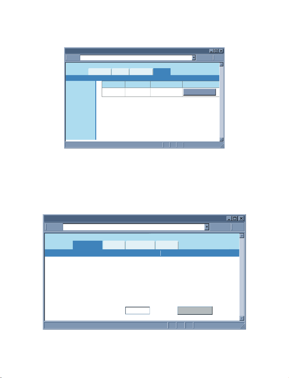
This page provides the number of Ethernet packets received or transmitted. Pressing the
Reset Counter button will set the counts to zero.
Figure 4.26 Diagnostics
4.4.8 Log Out
Once you click on Log Out, you will be logged out, and taken back to the Welcome page.
4.5 Readings
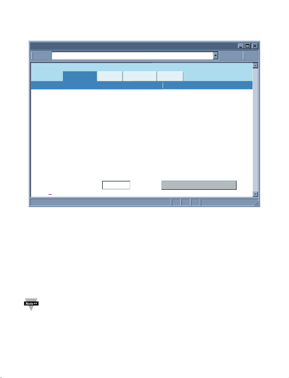
This page displays temperature, humidity, and dew point.
It can be displayed either as an HTML page or a Java applet.
4.5.1 HTML
Figure 4.27 Readings: HTML
Refresh – Adding a time value in seconds will automatically update the HTML page with
fresh readings.
Diagnostics
http://192.168.1.200Address
Overview
Network
Configuration
Management
Security
System
Diagnostics
Log Out
Readings
Ethernet Received Transmitted
Packets 4437 6073
Chart
Web Link Setup
Reset Counter
Readings
http://192.168.1.200Address
Readings
Chart
Web Link Setup
JavaHTML
Temperature
Humidity
Dewpoint
Refresh
2
Seconds
23.0 C
47.3%
11.0 C
Auto Update
Page 41
35
4.5.2 Java
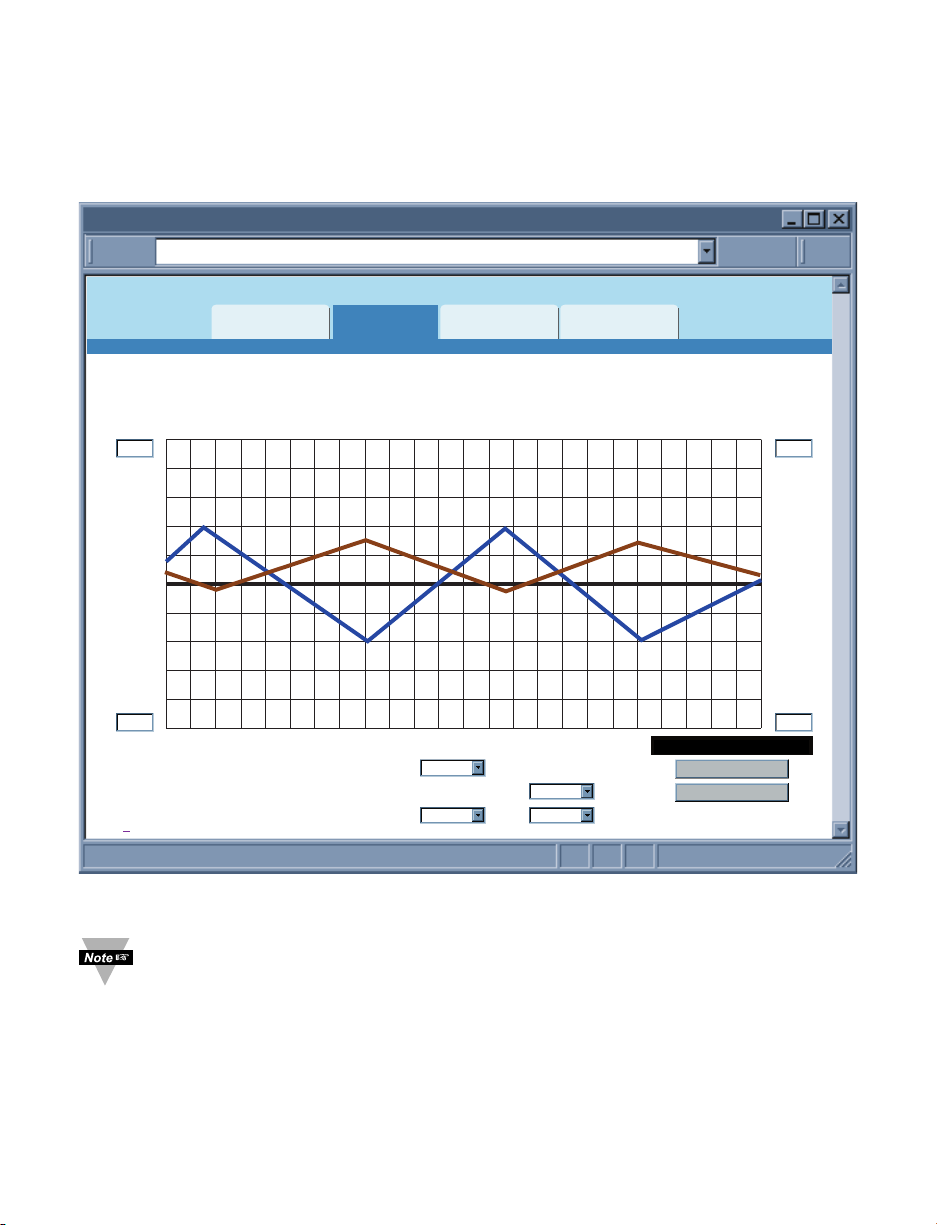
If Java option is chosen installation of Java Runtime is required (refer to Appendix G).
Figure 4.28 Readings: Java
Data Logging – This option will require the Java Policy file to be setup.
Press on Help[?] for details.
An alternate way to set up the Java Policy can be found in Appendix G.
Once the Java Policy file is completed, click on Data Logging button to log the data
displayed on this page into a file. The file is in comma separated values (.csv) format,
which can be opened in Excel or as ASCII. The fields are separated by a comma ( , ).
When the button is ACTIVE it means that the data is currently being logged into a file.
The value in seconds in the Refresh box determines how often the data is being logged.
The default is 2 seconds.
If a blank screen appears without any “java application running” or image of a
“Java logo”, please verify you have the latest Java Runtime Environment installed
and configured according to the instructions (refer to Appendix G). If you do not
have Java Runtime Environment installed, you may download it from our website
(in the software section) or contact the Customer Service Department nearest you.
“Java and the Java Coffee Cup Logo are trademarks or registered trademarks of Sun Microsystems, Inc. in the U.S. and other countries."
Readings
http://192.168.1.200Address
Readings
Chart
Temperature
Humidity
Dewpoint
2Refresh
Help[?]
Web Link Setup
JavaHTML
Seconds
Data Logging: INACTIVE
23.0 C
47.3%
11.0 C
Page 42
36
4.6 Chart
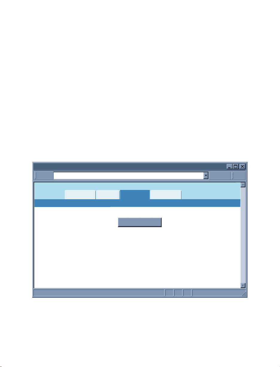
This page charts the temperature, humidity, and dew point in real-time across the full span
(-40 to 124ºC, and 0 to 100% RH) or within any narrow range (such as 20 to 30ºC).
The time-base can display one minute, one hour, one day, one week, one month or one
year.
Figure 4.29 Adjustable Chart
If a blank screen appears without any “java application running” or image of a
“Java logo”, please verify you have the latest Java Runtime Environment
installed and configured according to the instructions (refer to Appendix G).
If you do not have Java Runtime Environment, you may download it from our
website (in the software section) or contact the Customer Service Department
nearest you.
Chart
http://192.168.1.200Address
Readings Chart Web Link Setup
Max. 130.1 / Min. 95.9 Max. 69.9 / Min. 30.1
Temperature Humidity
200
108.2 F 50.8 %
100
20.0
C/Div
0
Data Source:
Alarm Relay Set Points:
Help[?]
Live
Bold
1 Hour/Div
X-axis: 1 Day
Y-axis (left): Temperature Style: Bold
Y-axis (right):
Humidity Style: Bold
Thu Nov 18 12:05:07 PDT 2010Thu Nov 18 08:00:00 PDT 2010
Save Chart
Print Chart
10.0
%/Div
0
Page 43
37
4.6 Chart (continued)
Max. / Min. – This shows the maximum and minimum values for Temperature and
Humidity (or Dewpoint) indicated on the Y-axis.
X-axis – This indicates the time, options includes one minute, one hour, one day, one
week, one month or one year.
Y-axis – The left Y-axis is dedicated to temperature. Either humidity or dewpoint can be
selected for the right Y-axis.
Style – This option will hide or chart (normal) the graph of the variables (temperature,
humidity and dew point). The bold option will thicken the displayed graphs.
Save Chart – Save the current graph in PNG (Portable Network Graphics) format. The
filename has extension .png. This option will require the Java Policy file to be setup.
Press on Help[?] for details. An alternate way to set up the Java Policy can be found in
Appendix G.
Print Chart – The displayed chart will be printed once the button is clicked.
4.7 Web Link
This page is configured from the Network menu under IP configuration.
Refer to Section 4.4.2.1.
Figure 4.30 Web Link
Web Link
http://192.168.1.200Address
Readings
Chart
Web Link Setup
Web Link
Page 44
38
4.8 Telnet Setup
With a telnet program, you can connect to the iServer using its IP address and TCP Port
2000. In Continuous mode (refer to Configuration:Sensors page Section 4.4.3.2), the
telnet session will receive continuous data (temperature and humidity) from the iServer.
In Command mode, a command can be sent to query the iServer.
Refer to Section 4.9.1 for list of commands.
4.8.1 Telnet Connection
Telnet stands for Telecommunications Network, it is a protocol that provides a way for
users to connect to a node with a valid IP address anywhere on an Ethernet network or
the Internet . You can open a Telnet session using a terminal emulation programs like
Tera Term (downloadable from the internet), which is a free software for Windows.
You can initiate a telnet connection by typing the IP address of the iServer, and Port
2002 for logging into the iServer’s telnet consol port (see Figure 4.31). By telneting to
Port 2000, you will be able to access temperature, humidity, and dew point readings.
The default password for Telnet Login is 00000000 and can be changed if
desired.
Figure 4.31 Tera Term Telnet Connection Screen
Once the connection is established you will be prompted for an Administrator Password
(default is 00000000). Telnet console port (2002) allows users to configure some
parameters within the iServer. Figure 4.33 shows the parameters that can be changed.
After connecting to the iServer, you can use the following commands to read, modify, and
get help.
p displays the current settings (Figure 4.32)
? displays all the available options as well as an example on how to enter a
command (Figure 4.33)
s set a new configuration (see the example in Figure 4.33), sending the
command c is required to permanently store the new settings
RESET restart the iServer
FACTORY set the iServer to it’s factory default, the RESET command is required after
the FACTORY command
c permanently store the new settings
q quit the telnet session
Te ra Ter m : N ew Co n ne c ti o n
192.168.1.200
Host:TCP/IP:
S
erial:
ort#:
2002TCP p
lnet
Te
COM1: Communications Port {COM1
Cancel H
Protocol:
UNSPEC
elpOK
Page 45
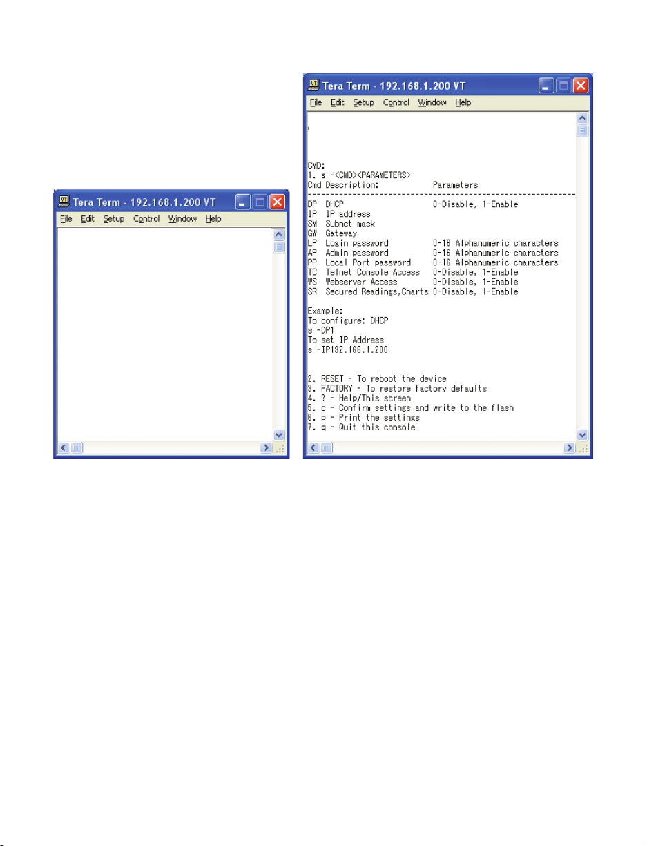
39
4.8.1 Telnet Connection (continued)
Figure 4.32 Figure 4.33
Telnet to port 2002 – p command Telnet to port 2002 – ? command
4.9 HTTPget Program
The HTTPget software is used to send a single HTTP or TCP request to an iServer
product. In contrast, the telnet or Hyperterminal programs allow a continuous
connection with multiple requests to be sent to the iServer product.
Generally HTTPget is used for simply programming an IP address to the iServer or for
quickly obtaining a reading of from a device.
The iServer product must be configured from the configuration web page so that the
"Server Type" value is set to "Command", refer to Section 4.4.3.2.
4.9.1 HTTPget using Port 2000
You can setup and read the information from the iServer by using the HTTPget program.
The following program can be used to read data from the iServer by using TCP port
2000. The command string is sent to this TCP port, then the response can be read back
from the same socket.
The HTTPget.exe file is used to setup and read information from the iServer. This file can
be downloaded from the website listed on the cover of this manual (software section).
1.00
Administrator Password?00000000
iTHX>
iTHX>p
Model: iTHX
Firmware Ver: 1.0.0
DP: Disabled (0)
MC: 00:03:34:00:B9:B6
IP: 192.168.1.200
SM: 255.255.255.0
GW: 0.0.0.0
LP: 12345678
SP: 00000000
CP:
TC: Enabled (1)
WS: Enabled (1)
SR: Enabled (1)
iTHX>
1.0.0
Administrator Password?00000000
iTHX>
iTHX>Configuration Commands:
iTHX>
Page 46

40
4.9.1 HTTPget using Port 2000 (continued)
Notes on using HTTPget :
The HTTPget.exe program should be installed to the windows directory (usually c:\winnt
or c:\windows)
1. Open up a command window (or have a DOS window)
a) Click on start menu
b) Click on "Run"
c) In the dialog box that appears, type "cmd" or "command" and click on "OK" button.
d) A command window should now appear.
2. If you now type "httpget" and press the "enter" key, the program options should be
displayed.
3. Next run HTTPget with the options displayed below
httpget -r -S “*SRTC\r” 192.168.1.200:2000
where:
-r –S are parameters needed for the command string
*SRTC is the command as the following:
*SRTC Read the temperature in C, celcius
*SRTF Read the temperature in F, fahrenheit
*SRH Read humidity
*SRD Read the dew point in C
*SRDF Read the dew point in F
*SRB Read the temperature in C and humidity
*SRBF Read the temperature in F and humidity
*SRYRST Reset Power on
\r is the carriage return termination character
192.168.1.200 is an IP address
2000 is a socket port number
Response:
076.6 (in Deg.F format)
Page 47
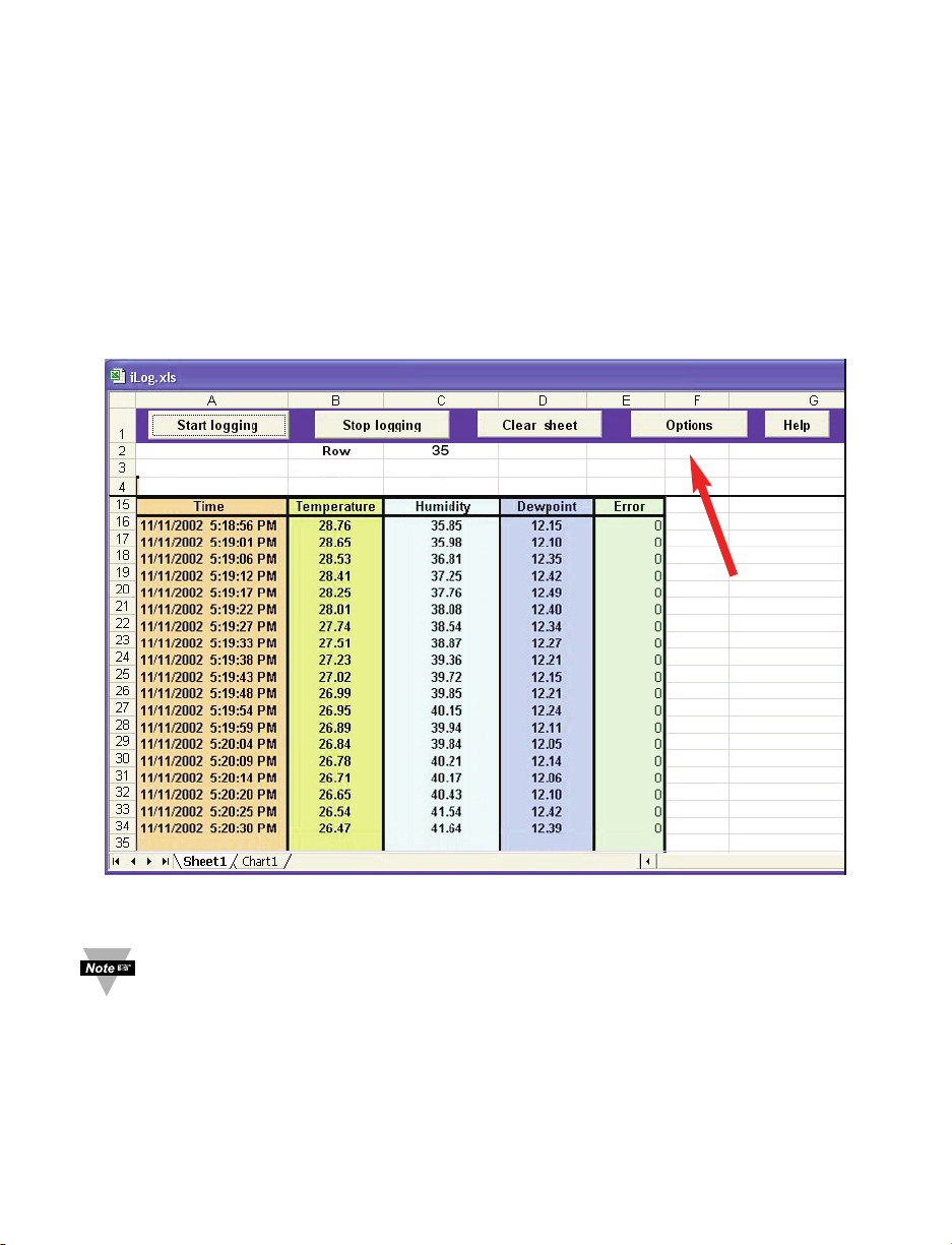
41
4.10 iLog Software
This is an Excel application software that can log temperature, humidity and dewpoint
from the iServer over the local network (Ethernet) or the internet.
a) Download the iLog software from the website listed in this manual.
b) Install iLog software on a networked PC. This software is compatible with Windows
95, 98, NT, 2000, XP, Windows Vista and Windows 7 (32 and 64-bit).
c) If you have Excel 2007 or higher, when installing iLog choose “Custom” installation
option and on the next window check the box for “Excel 2007 Apps” and continue
the installation to the end.
d) For complete information of how to use the iLog software, click on the HELP button.
e) There is a list of Error Messages in Appendix E.
Figure 4.34 iLog Software Logging Data
The Options button will let you select the product model.
Choose iTHX-M from the Model Selection pull-down menu (from General tab).
Page 48

42
4.10 iLog Software (continued)
Table 4.1 iLog Excel Applications
The iLog application actually consists of several Excel files, though most supported
devices can be accessed by the main iLog program. The main program is listed as
"iLog", plus a version number, under the Start Menu program links (those links available
by clicking the Start button on the Windows taskbar).
In the following table, the iLog File column shows how many sensors are logged by the
main iLog file. If more than 3 sensors are available, then the Alternate column shows
how many sensors the device can support. Devices with more than 3 sensors will have
their own Excel file. For these files, click on the model device found in the Start Menu.
Networked Product iLog File Alternate
iTHX-W3, iTHX-D3, iTHX-W, -2 3 column
iTHX-M, iTHX-SD 3 column
iTHX-W, -2 (dual probe) 1st probe / 3 column 6 column
iSE-TC, iSD-TC 3 column 5 column
iSE-TH, iSD-TH 3 column 5 column
iBTHX-W, iBTHX-D 3 column 4 column
iBTX-W/-D, iBTX-M, iBTX-SD 2 column
iPTX-W 2 column
iTCX 3 column
iTH Controller 3 column
iVI 3 column 4 column
iSeries 1 column
iDRX/iDRN 1 column
INF-B 1 column
Wireless Devices
The "Auto" column shows number of columns per remote device that are possibly
displayed.
The Full column shows number of columns allocated per device for the "Full"
spreadsheet, which will be able to display all data for all active devices.
Networked Product Auto Full
zSeries Receiver and Remotes 1 to 4 column / device 4 column / 32 device
wiSeries with zED Remotes 1 to 2 column / device 2 column / 32 device
UWTC REC-3 and Remotes 1 or 2 column / device 2 column / 32 device
wiSeries with UWTC Remotes 1 to 2 column / device 2 column / 32 device
The active wireless devices, when shown in the Excel application, will be shown with
the device number and the units returned.
Page 49

PART 5 SPECIFICATIONS
SENSOR SPECIFICATIONS
!"#$%&'"()*+&,&%-(.!)/
011*2$1-#!$34"($%(5678 $%&'()*+,-*./*0,*1/)2*
?(=>3?8>3,"3;&34<
)-;%"2";&;< $.)*6;
=>3?#&3"$2&%-< $")
!";9>3;"(@&+"< <*=78,45=>*03?*@")*A0:B7*+,-*-7389:4C*@")*,+*3*=07D
!"9"$%$A&#&%-< $/&.)
!";>#*%&>3< /&.)>*.%J:0
@"+9"2$%*2"(.@/
011*2$1-F!$34"G<
H$3,(I2>A"<( $/&(LG*+,-*(L*0,*!(LG*A$.LO*+,-*!.L*0,*.."LOI2
J3,*;%2&$#(I2>A"<(
!";9>3;"(@&+"< (*0,*"/*=78,45=>*03?*@")*A-7=D,4=7*0:B7*57D745=*,4*9730
!"9"$%$A&#&%-< $/&.LG
!";>#*%&>3< /&.LG>*.!*J:0
$")*+,-*(*0,*./)*345*1/*0,*1()
$!)*+,-*/*0,*()*345*1(*0,*.//)
67+7-*0,*893-0*:4*099"3,&:()
+?480:,4>*E3F:5*30*%(G*345*.B#=*3:-+F,HI
=B@C< 678,45:0:,4:4C*,+*097*D-,J7*B3K*J7*4787==3-K*:+
097*D-,J7*:=*=0,-75*+,-*3*D7-:,5*,+*0:B7*:4*3*93-=9
74E:-,4B740*A07BD7-30?-7=*J7F,H*/LG**,-*3J,E7*'/LG*,7MD,=?-7*0,*897B:83F*E3D,-=>*8,4574=30:,4>*708I&
N,*-78,45:0:,4*097*D-,J7*-7+7-*0,*099"3,&:()DE
?D*0,*$.LG*+,-*/L*0,*(LG*345*!(L*0,*'/LG*
A?D*0,*$%LO*+,-*"%L*0,*!.LO*345*.."L*0,*.(<LOI
67+7-*0,*893-0*:4*099"3,&:()
$/&(LG +,-*(L*0,*!(LG*A*$.LO*+,-*!.*0,*.."LOI2*
?D*0,*$.&(LG*+,-*P!/L*0,*(LG*345*!(L*0,*.%
!LG*
A?D*0,*$%&'LO*+,-*P!/L*0,*!.LO*345*.."L*0,*%((LOI
67+7-*0,*893-0*:4*099"3,&:()
QRM074575*07BD7-30?-7*-34C7*:=*+,-*:45?=0-:3F*D-,J7*,4FK>
097*:S7-E7-T=*,D7-30:4C*07BD*:=*/*0,*'/LG*A"%*0,*.(<LOI*
+,-*:N;UPV"*H:09*H3452*P!/*0,*<(LG*AP!/*0,*.<(LOI*
+,-*:N;UPW">*:N;UPV"P%*,-*:N;UPV"P(
83D38:0K*,+*345*097-B3F*-7=:=03487*0,*=74=,-*=?J=0-307I
PROBE SPECIFICATIONS
H$3,(I2>A"X* .1<*BB*F,4C*M*.1*BB*5:3B707-*A'&<Y*M*/&'(YI
G3JF7*H:09*WZ1*8,44780,-X*.(%*BB*F,4C*A@YI
G3JF7*,D7-30:4C*07BD7-30?-7X**/*0,*</LG*A"%*0,*.'@LOI
J3,*;%2&$#(I2>A"X* ."'BB*or (.BB*F,4C*M*.@BB*5:3B707-*A(Y*or %Y*M*/&@"YI
G3JF7*H:09*WZ1*8,44780,-X*"B*or /&1B*F,4C*A./T*or "TI
G3JF7*,D7-30:4C*07BD7-30?-7X**P!/*0,*.%(LG*AP!/*0,*%('LOI
!"
Page 50

44
iSERVER SPECIFICATIONS
Interfaces
Ethernet (RJ45): Fixed or auto-negotiating 10/100Base-T; Auto MDI/MDIX
Sensor: Digital 4-wire (DB-9) iTHX-W3;
Removable 4 position screw terminal: iTHX-D3
Supported Protocols: TCP, UDP, SNMP, SMTP, SNTP, ARP, ICMP, DNS, DHCP,
HTTP, and Telnet
LED Indicators: 100BASE-T, Network Link and Activity, DHCP, Recording
Management: Device configuration and monitoring through embedded
WEB server
Embedded WEB Server: Serves WEB pages containing real-time data and live
updated charts within definable time intervals.
POWER
Power Input: 5 Vdc @ 200 mA max: iTHX-W3
10 to 32 Vdc: iTHX-D3
Safety Qualified (included)
ac power adapter: Nominal Output: 5Vdc @ 600 mA
Input: 100 to 240 Vac, 50/60Hz included: iTHX-W3
Switching Power Supply Sold separately for the iTHX-D3
Consumption: 2 W
max for iTHX-W3; 2.5 W max for iTHX-D3
ENVIRONMENTAL
Operating Temperatures
iServer Unit: 0 to 70°C (32 to 158°F) for iTHX-W3 with wand;
-40 to 85°C (-40 to 185°F) for iTHX-D3, iTHX-W3-2 or
iTHX-W3-5
ac Power Adapter: 0 to 40°C (32 to 104°F)
Wand Cable: 0 to 80°C (32 to 176°F)
Industrial Cable: -40 to 125°C (-40 to 257°F)
Storage Temperature: -40 to 85°C (-40 to 185°F)
Material: Valox 364 PBT case with wa l l mount bracket: i THX-W3;
Polycarbonate case with DIN Rai l mount: iTHX-D3
Weight (with probe):
0.31 kg (0.68 lbs) iTHX-W3; 0.31 kg (0.68 lbs) iTHX-D3
GENERAL
Agency Approvals: FCC-B, CE
Software: Compatible with Windows operating systems
Firmware upgrade from Ethernet
OPC Server
iConnect: Configuration software for the Ethernet interface
iLog: Macro for automatic data logging in MS Excel
Page 51

45
Appendix A GLOSSARY
User of this manual should be familiar with following definitions:
ARP (Address Resolution Protocol) is a protocol for mapping an Internet Protocol
address (IP address) to a physical machine address that is recognized in the local
network. For example, the IP address in use today is an address that is 32-bits long.
In an Ethernet local area network, however, addresses for attached devices are 48-bits
long. (The physical machine address is also known as a Media Access Control or MAC
address.) A table, usually called the ARP cache, is used to maintain a correlation between
each MAC address and its corresponding IP address. ARP provides the protocol rules for
making this correlation and providing address conversion in both directions.
Ethernet is a network protocol defined by the IEEE 802.3 standard. Ethernet-based
networks use MAC Address rather then IP Address to exchange data between computers.
By using ARP and adding TCP/IP support, Ethernet devices may be connected as part of
the Internet. An Ethernet LAN typically uses coaxial cable or special grades of twisted pair
wires. The most commonly installed Ethernet systems are called 10BASE-T and provide
transmission speeds up to 10 Mbps. Devices are connected to the cable and compete for
access using a Carrier Sense Multiple Access with Collision Detection (CSMA/CD)
protocol.
IP (Internet Protocol) is the method or protocol by which data is sent from one computer
to another on the Internet.
IP address (Internet Protocol address) is a 32-bit number that identifies each sender or
receiver of information that is sent in packets across the Internet.
IP Netmask is a 32-bit pattern of bits used to determine which part of the IP address is the
network portion and which part is the host portion.
MAC (Media Access Control) Address is your computer's unique hardware number.
When you're connected to the Internet from your computer, a correspondence table relates
your IP address to your computer's physical (MAC) address on the LAN.
Ping is a utility that tests the network connectivity. It is used to determine if the host is
capable of exchanging information with another host.
Port number/Socket number is a way to identify a specific process to which an Internet
or other network message is to be forwarded when it arrives at a server. It is a predefined
address that serves as a route from the application to the Transport layer or from the
Transport layer to the application of the TCP/IP system.
Sockets are a method for communication between a client program and a server program
in a network and defined as "the endpoint in a connection." Information transferred across
the Internet primarily occurs between sockets.
TCP/IP (Transmission Control Protocol/Internet Protocol) is the basic communication
language or protocol of the Internet. When you are set up with direct access to the
Internet, your computer is provided with a copy of the TCP/IP program just as every other
computer that you may send messages to or get information from also has a copy of
TCP/IP. TCP/IP often is used as a general term to indicate generic access to the Internet.
UDP/IP (User Datagram Protocol/Internet Protocol) is the TCP/IP standard protocol that
allows an application program on one machine to send a datagram to an application
program on another. The UDP can be either in Broadcast or Directed form. The Broadcast
UDP transmits data to every node on the same network. The Directed UDP transmits data
to one node only.
Page 52

46
Appendix B IP Address
An IP address is a unique 32-bit address assigned to a computer and includes:
• A network ID number identifying a network.
• A host ID number identifying a computer on the network.
All IP addresses have been divided into three smaller groups (classes) A, B and C
• Class A addresses have 8-bits of network ID and 24-bits of host ID. They can support
a large number of hosts, approximately 2 = 16,777,216 computers per network.
The IP addresses range in binary from 00000001.xxxxxxxx.xxxxxxxx.xxxxxxxx
to 01111111.xxxxxxxx.xxxxxxxx.xxxxxxxx
The IP addresses range in decimal from 1.x.x.x to 127.x.x.x
Class A network ID’s support a very large number of hosts.
• Class B addresses have 16-bits of network ID and 16-bits of host ID. They can
support approximately 216= 65,536 computers per network.
The IP addresses range in binary from 10000000 00000000.xxxxxxxx.xxxxxxxx
to 10111111 11111111.xxxxxxxx.xxxxxxxx
The IP addresses range in decimal from 128.0.x.x TO 191.255.xxx.xxx
Class B network ID’s support a medium number of hosts.
• Class C addresses have 24-bits of network ID and 8-bits of host ID. They can support
approximately 28= 256 computers per network.
The IP addresses range in binary from 11000000.00000000.00000000.xxxxxxxx
to 11011111.11111111.11111111.xxxxxxxx
The IP addresses range in decimal from 192.0.0.xxx to 223.255.255.xxx
Class C network ID’s support a small number of hosts.
The rest of the addresses are divided into two classes, D and E.
Class D networks are not assigned to the host. They are used for multicasting.
The address range from 224.x.x.x to 239.x.x.x
Class E networks are experimental or reserved addresses.
The address range from 240.x.x.x to 247.x.x.x
Page 53
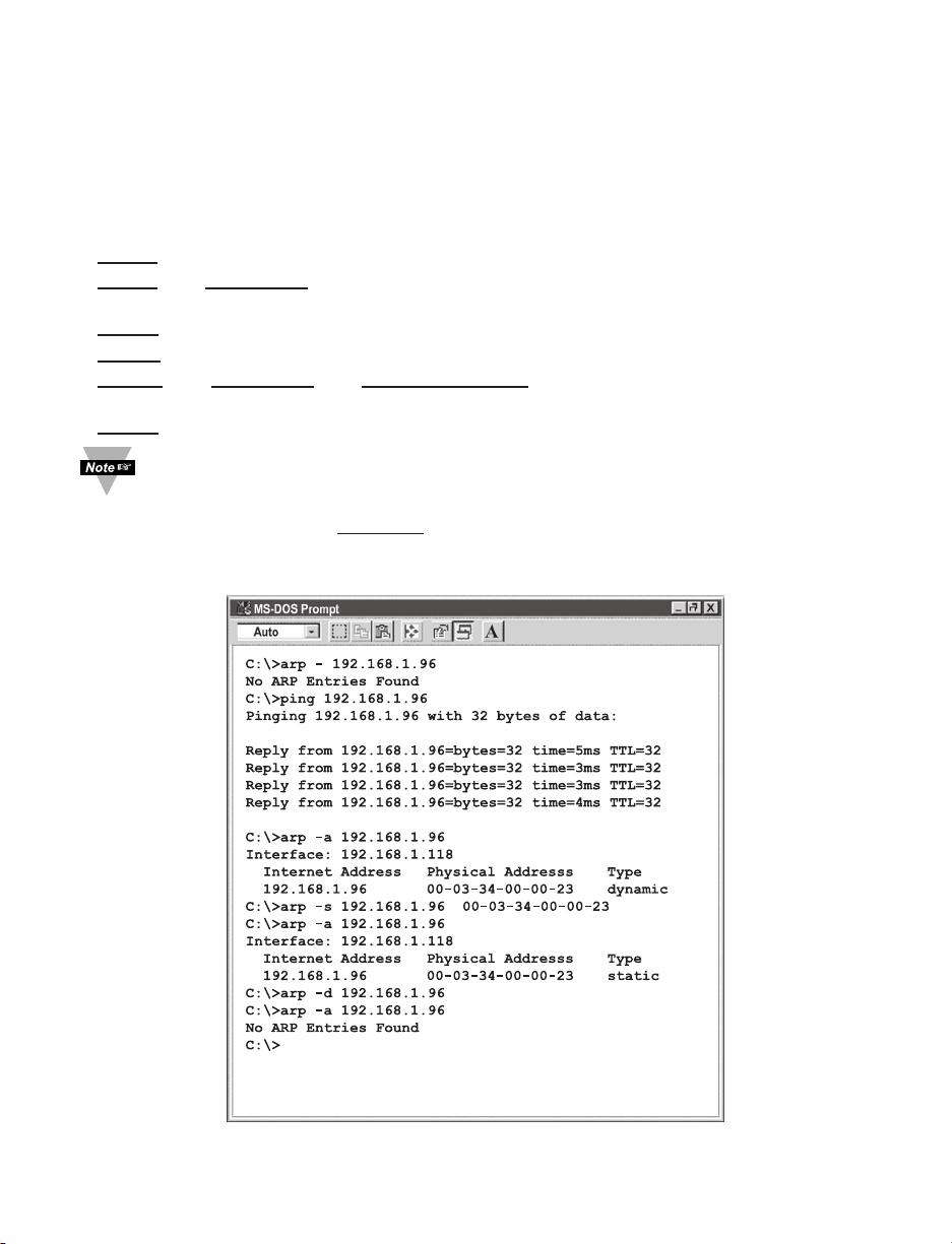
47
Appendix C ARP Commands
ARP is the Internet layer protocol responsible for matching or obtaining the MAC
(hardware) address that corresponds to a particular IP address. The ARP command
allows the user to view the current contents of the ARP cache of the local computer
(residing on the same network). Microsoft includes the ARP.EXE utility for viewing and
modifying the ARP cache with its Windows products. The following ARP commands can
be used to view cache entries:
• arp –a ! Use this command to view all ARP cache entries.
• arp –a plus IP address ! Use this command to view ARP cache entries associated
with one particular interface on a network with multiple adapters.
• arp –g ! Same as arp –a.
• arp –N ! Use this command to display ARP entries for specific network interface.
• arp – s plus IP address plus Physical address ! Use this command to manually
add a permanent static entry to the ARP cache.
• arp –d ! Use this command to manually delete a static entry.
Ping the destination computer using IP address first before using the arp -a
command.
The following window shows examples of arp commands and responses.
• Your computer has an IP address of 192.168.1.118
• The destination computer has an IP address of 192.168.1.96
Figure C.1 ARP Commands and Responses
Page 54

Appendix D IP Netmask
IP Netmask or Subnet Mask is a 32-bit pattern of ones and zeros used to determine
network portion of an IP address from the host portion of the IP address. Subnet mask is
a network ID that is created by borrowing bits from host portion of IP address and using
them as part of a network ID. The table below shows a default subnet mask for address
Classes A, B, and C. Each bit that is set to "1" in the subnet mask corresponds to the bit
in the IP address that is to be used as the network ID. Each bit that is set to "0" in the
subnet mask corresponds to a bit in the IP address that is to be used as the host ID.
Address Class Mask Binary Value Mask Decimal Value
or Dotted Notation
Class A 255.0.0.0
Class B 255.255.0.0
Class C 255.255.255.0
If your network requires more network ID’s, you can extend the default subnet mask to
include additional bits from the host ID. This allows for additional network ID’s within the
network. The table below shows some examples of subnet masks and bits moved from
the hosts ID to create a new subnet.
Mask Dotted Notation Mask Binary Mask Bits
Class A
255.0.0.0 (Default) 0
255.192.0.0 2
255.224.0.0 3
255.240.0.0 4
255.248.0.0 5
255.252.0.0 6
255.254.0.0 7
255.255.0.0 8
255.255.128.0 9
255.255.192.0.0 10
……………......... .
255.255.255.252 22
Class B
255.255.0.0 (Default) 0
255.255.192.0 2
……………......... .
255.255.255.252 14
Class C
255.255.255.0 (Default) 0
255.255.255.192 2
…………………. .
255.255.255.254 6
To determine the number of valid hosts ID’s remaining after subnetting, use the following
equation: 2
n
– 2, where n is the number of octet digits left after the subnet mask.
48
11111111
11111111
11111111
00000000
11111111
11111111
00000000
00000000
11111111
00000000
00000000
00000000
11111111
11111111
11111111
11111111
11111111
11111111
11111111
11111111
11111111
11111111
........
11111111
00000000
11000000
11100000
11110000
11111000
11111100
11111110
11111111
11111111
11111111
........
11111111
00000000
00000000
00000000
00000000
00000000
00000000
00000000
00000000
10000000
11000000
........
11111111
00000000
00000000
00000000
00000000
00000000
00000000
00000000
00000000
00000000
00000000
........
11111100
11111111
11111111
........
11111111
11111111
11111111
........
11111111
00000000
11000000
........
11111111
00000000
00000000
........
11111100
11111111
11111111
........
11111111
11111111
11111111
........
11111111
11111111
11111111
........
11111111
00000000
11000000
........
11111100
Page 55

Appendix E ASCII Chart
ASCII Dec Hex Binary ASCII Dec Hex Binary
Char No Parity Char No parity
NUL 00 00 00000000 @ 64 40 01000000
SOH 01 01 00000001 A 65 41 01000000
STX 02 02 00000010 B 66 42 01000010
ETX 03 03 00000011 C 67 43 01000011
EOT 04 04 00000100 D 68 44 01000100
ENQ 05 05 00000101 E 69 45 01000101
ACK 06 06 00000110 F 70 46 01000110
BEL 07 07 00000111 G 71 47 01000111
BS 08 08 00001000 H 72 48 01001000
HT 09 09 00001001 I 73 49 01001001
LF 10 0A 00001010 J 74 4A 01001010
VT 11 0B 00001011 K 75 4B 01001011
FF 12 0C 00001100 L 76 4C 01001100
CR 13 0D 00001101 M 77 4D 01001101
SO 14 0E 00001110 N 78 4E 01001110
SI 15 0F 00001111 O 79 4F 01001111
DLE 16 10 00010000 P 80 50 01010000
DC1 17 11 00010001 Q 81 51 01010001
DC2 18 12 00010010 R 82 52 01010010
DC3 19 13 00010011 S 83 53 01010011
DC4 20 14 00010100 T 84 54 01010100
NAK 21 15 00010101 U 85 55 01010101
SYN 22 16 00010110 V 86 56 01010110
ETB 23 17 00010111 W 87 57 01010111
CAN 24 18 00011000 X 88 58 01011000
EM 25 19 00011001 Y 89 59 01011001
SUB 26 1A 00011010 Z 90 5A 01011010
ESC 27 1B 00011011 [ 91 5B 01011011
FS 28 1C 00011100 \ 92 5C 01011100
GS 29 1D 00011101 ] 93 5D 01011101
RS 30 1E 00011110 ^ 94 5E 01011110
US 31 1F 00011111
_
95 5F 01011111
SP 32 20 00100000
`
96 60 01100000
! 33 21 00100001 a 97 61 01100001
" 34 22 00100010 b 98 62 01100010
# 35 23 00100011 c 99 63 01100011
$ 36 24 00100100 d 100 64 01100100
% 37 25 00100101 e 101 65 01100101
& 38 26 00100110 f 102 66 01100110
‘ 39 27 00100111 g 103 67 01100111
( 40 28 00101000 h 104 68 01101000
) 41 29 00101001 I 105 69 01101001
* 42 2A 00101010 j 106 6A 01101010
+ 43 2B 00101011 k 107 6B 01101011
, 44 2C 00101100 l 108 6C 01101100
- 45 2D 00101101 m 109 6D 01101101
. 46 2E 00101110 n 110 6E 01101110
49
Page 56

Appendix E ASCII Chart Continuation
/ 47 2F 00101111 o 111 6F 01101111
0 48 30 00110000
p
112 70 01110000
1 49 31 00110001
q
113 71 01110001
2 50 32 00110010 r 114 72 01110010
3 51 33 00110011 s 115 73 01110011
4 52 34 00110100 t 116 74 01110100
5 53 35 00110101 u 117 75 01110101
6 54 36 00110110 v 118 76 01110110
7 55 37 00110111 w 119 77 01110111
8 56 38 00111000 x 120 78 01111000
9 57 39 00111001
y
121 79 01111001
: 58 3A 00111010 z 122 7A 01111010
; 59 3B 00111011
{
123 7B 01111011
< 60 3C 00111100
|
124 7C 01111100
= 61 3D 00111101
}
125 7D 01111101
> 62 3E 00111110 ~ 126 7E 01111110
? 63 3F 00111111 DEL 127 7F 01111111
ASCII Control Codes
ASCII Dec Hex Ctrl Key Definition ASCII Dec Hex Ctrl Key Definition
Char Equiv. Char Equiv.
NUL 00 00 Crtl @ Null Character DC1 17 11 Crtl Q Data Control 1
- XON
SOH 01 01 Crtl A Start of DC2 18 12 Crtl R Data Control 2
Header
STX 02 02 Crtl B Start of Text DC3 19 13 Crtl S Data Control 3
- XOFF
ETX 03 03 Crtl C End of Text DC4 20 14 Crtl T Data Control 4
EOT 04 04 Crtl D End of NAK 21 15 Crtl U Negative
Transmission Acknowledge
ENQ 05 05 Crtl E Inquiry SYN 22 16 Crtl V Synchronous
Idle
ACK 06 06 Crtl F Acknowledge ETB 23 17 Crtl W End of Trans
Block
BEL 07 07 Crtl G Bell CAN 24 18 Crtl X Cancel
BS 08 08 Crtl H Back Space EM 25 19 Crtl Y End of Medium
HT 09 09 Crtl I Horizontal SUB 26 1A Crtl Z Substitute
Tabulation
LF 10 0A Crtl J Line Feed ESC 27 1B Crtl [ Escape
VT 11 0B Crtl K Vertical FS 28 1C Crtl \ File Separator
Tabulation
FF 12 0C Crtl L Form Feed GS 29 1D Crtl ] Group
Separator
CR 13 0D Crtl M Carriage RS 30 1E Crtl | Record
Return Separator
SO 14 0E Crtl N Shift Out US 31 1F Crtl
_
Unit Separator
SI 15 0F Crtl O Shift In SP 32 20 Space
DLE 16 10 Crtl P Data Link
Escape
50
Page 57

Appendix F iLog Error Messages
Table F-1 iLog Error Messages
Error # Description Note
-8003 User stopped logging readings.
-10005 Failed to find the iServer. Ethernet cable is disconnected,
iServer is powered off, connections
across the firewall require longer
“connection to socket time out”
setting.
-10006 Windows socket was closed.
-10007 Windows socket error. Wrong IP or wrong Port number
was used.
-10008 The iServer failed to respond to a request. Wrong IP or wrong Port number
was used.
-10011 Response came empty. No data was sent.
-10012 Device responded with Possibly the iLog is configured for
"Serial Time Out" string. wrong product model.
-10014 Terminal Server Mode when the Port is 1000. Try Port 2000 in iLog configuration.
-15100 Error on obtaining the temperature reading. Possibly the iLog is configured for
wrong product model.
-15105 Error on obtaining the humidity reading. Possibly the iLog is configured for
wrong product model.
-15110 Error on obtaining the dew point reading. Possibly the iLog is configured for
wrong product model.
51
Page 58
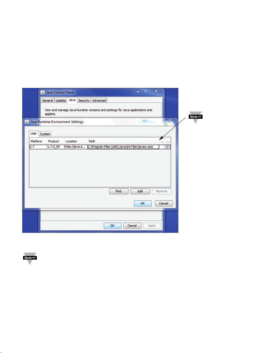
Appendix G Java Runtime Environment Setup
G.1 Java Runtime Environment Setup
If your computer does not have Java installed, please download from java.sun.com. You
can change the Java setting by clicking its icon in Control Panel. To load the applet, you
have to enable the web browser and disable cache.
G.1.1 Java Runtime Environment 1.7 Setup instructions
1. Go to your computer's Control Panel. Open the Java Plug-in.
Figure G.1 Java 1.7 Screen Shot
The "Data Logging" button on the "Readings" page, "Save Chart" button on the
"Chart" page, and the "Retrieve" button on the "Recording Data Retrieval" page
will not be active if the instructions explained in the above are not followed.
52
Verify that
the path is
correct.
Page 59

G.2 Browser Proxy Selection
Accessing iServer within your internal network
• Usually when the computer and iServers are on an internal network, you will not use
Proxy server access.
• You should un-check the "Use Browser Settings" option on the "Proxy" tab.
Accessing iServers units using the internet
• Often the web browser will use Proxy server access to the internet. In such cases,
the default Java runtime settings on the "Proxy" tab should suffice. The default
setting is the "Use Browser Settings" option.
• If the default proxy setting doesn't work, then you may have a situation where the
proxy settings of the web browser are incorrect.
Diagnostics:
If the web page of the iServer appears, then the HTTP Proxy is working fine.
If the data isn't updated on the iServer upon selecting the "Readings" or "Chart" web
page, there may be a problem with access through a winsock proxy server. In such
cases your network administrator will need to provide the winsock proxy server and port
#s. .
These values should be entered into the Socks line on the "Proxy" tab (of the Java
Plugin control panel) or into the "connections" tab on the View,Internet Options dialog
and make sure that the Proxy tab shows that the "Use Browser Settings" option is not
selected (i.e. when you specify proxy connections in the Java Plugin control panel).
Accessing iServer units over Peer-to-Peer network
A simple peer-to-peer network is setup by disconnecting from the main network (as users
will often do when trying to do initial setup of the iServer) and then connecting the
iServer to another computer using an ethernet hub, an ethernet switch, or a Cross-over
cable connection.
Often when using a peer-to-peer network, the Java plugin and the web browser (such as
Internet Explorer) have internet connections configured to connect through proxy
servers. In such case, you will need to simply assign the final IP address on this peer to
peer network and then view the iServer charts after connecting the iServer into the
regular network. Otherwise you can disable the Java plug-in's "Use Browser Settings"
temporarily and then reconfigure the Java plug-in settings for regular network access
after testing the iServer chart access on your peer-to-peer network.
The "Use Browser Settings" should not be selected. And the HTTP and Socks proxy
entries should be blank. Also, setup the internet browser so that proxy servers are disabled.
53
Page 60
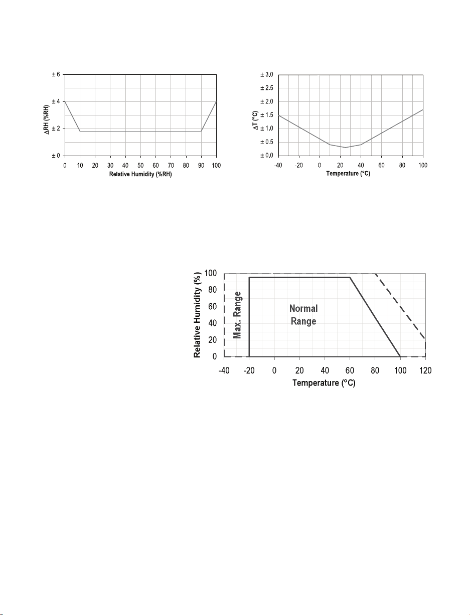
Appendix H Sensor Information
H.1 Accuracy
Figure H.1 Figure H.2
RH Accuracy Chart Temperature Accuracy Chart
Accuracies are tested at Manufacture’s Outgoing Quality Control at 25°C (77°F) and 3.3V.
Values exclude hysteresis and non-linearity, and is only applicable to noncondensing
environments.
H.2 Operating Conditions
Sensor works stable within
recommended normal range – see
Figure. Long term exposures to
conditions outside normal range,
especially at humidity >80%RH,
may temporarily offset the RH
signal (+3 %RH after 60h). After
return to normal range it will slowly
return towards calibration state by
itself. See Section H.4
“Reconditioning Procedure” to
accelerate eliminating the offset.
Prolonged exposure to extreme
conditions may accelerate ageing.
Figure H.3 Normal Range
H.3 Storage Conditions and Handling Instructions
It is of great importance to understand that a humidity sensor is not a normal electronic
component and needs to be handled with care.
Chemical vapors at high concentration in combination with long exposure times may offset
the sensor reading. For these reasons it is recommended to store the sensors in original
packaging including the sealed ESD bag at following conditions: Temperature shall be in the
range of 10°C – 50°C (0 – 80°C for limited time) and humidity at 20 – 60%RH (sensors that
are not stored in ESD bags). For sensors that have been removed from the original
packaging we recommend to store them in ESD bags made of PE-HD8.
In manufacturing and transport the sensors shall be prevented of high concentration of
chemical solvents and long exposure times. Out-gassing of glues, adhesive tapes and
stickers or out-gassing packaging material such as bubble foils, foams, etc. shall be avoided.
Manufacturing area shall be well ventilated.
54
Page 61

Appendix H Sensor Information (continued)
H.4 Reconditioning Procedure
As stated above extreme conditions or exposure to solvent vapors may offset the sensor. The
following reconditioning procedure may bring the sensor back to calibration state:
Baking: 100 – 105°C at < 5%RH for 10h
Re-Hydration: 20 – 30°C at ~ 75%RH for 12h.
(75%RH can conveniently be generated with saturated NaCl solution. 100 – 105°C
correspond to 212 – 221°F, 20 – 30°C correspond to 68 – 86°F)
H.5 Temperature Effects
Relative humidity reading strongly depends on temperature. Therefore, it is essential to keep
humidity sensors at the same temperature as the air of which the relative humidity is to be
measured. In case of testing or qualification the reference sensor and test sensor must show
equal temperature to allow for comparing humidity readings.
The packaging of sensor is designed for minimal heat transfer from the pins to the sensor.
Still, if the sensor shares a PCB with electronic components that produce heat it should be
mounted in a way that prevents heat transfer or keeps it as low as possible. Furthermore,
there are self-heating effects in case the measurement frequency is too high.
H.6 Light
The sensor is not light sensitive. Prolonged direct exposure to sunshine or strong UV
radiation may age the housing.
H.7 Materials Used for Sealing / Mounting
Many materials absorb humidity and will act as a buffer increasing response times and
hysteresis. Materials in the vicinity of the sensor must therefore be carefully chosen.
Recommended materials are: Any metals, LCP, POM (Delrin), PTFE (Teflon), PE, PEEK, PP,
PB, PPS, PSU, PVDF, PVF. For sealing and gluing (use sparingly): Use high filled epoxy for
electronic packaging (e.g. glob top, underfill), and Silicone.
Out-gassing of these materials may also contaminate the sensor (see Section H.3).
Therefore try to add the sensor as a last manufacturing step to the assembly, store the
assembly well ventilated after manufacturing or bake at 50°C for 24h to outgas contaminants
before packing.
55
Page 62

Appendix J SNMP
Table J-1 SNMP MIB-2
Version: SNMPv1 Private Enterprise Number: .1.3.6.1.4.1.34089
MIB-2 (RFC 1213) supported: System Group
Object Identifier Object Description Access Default
(OID)
.1.3.6.1.2.1.1.1 sysDescr The name and version Read-only iTHX/ X.XX
identification of the product X.XX is the
firmware version
.1.3.6.1.2.1.1.2 sysObjectID The authoritative identification Read-only .1.3.6.1.4.1.34089.X.X
of the network management X.X is the product
subsystem contained in the system object ID
product. This value is allocated
within the SMI enterprises
subtree (1.3.6.1.4.1).
.1.3.6.1.2.1.1.3 sysUpTime The time since the system Read-only
was last re-initialized.
.1.3.6.1.2.1.1.4 sysContact The contact person for this Read-write None
node, together with
information on how to
contact this person.
.1.3.6.1.2.1.1.5 sysName The hostname of this node. Read-write ithxXXXX
XXXX are the last
4 characters of the
MAC address
.1.3.6.1.2.1.1.6 sysLocation The physical location of Read-write None
this node.
.1.3.6.1.2.1.1.7 sysServices The set of services that this Read-only 76
product primarily offers. Services include
The value is a sum of network application, end-to-end
layer services implemented. and internet
Table J-2 SNMP Trap
SNMP Trap (RFC 1157) version: SNMPv1
Generic trap type: enterpriseSpecific(6)
Specific Trap Alarm Description Specific Trap Alarm Description
0 Reading 1 7 Reserved
1 Reading 2 8 Reserved
2 Reading 3 9 Reserved
3 Reserved 10 Reserved
4 Power reset 11 Reserved
5 Sensor disconnected 12 Reserved
6 Reserved
56
Page 63

PART 6
APPROVALS INFORMATION
6.1 CE APPROVAL
This product conforms to the EMC directive 89/336/EEC amended by 93/68/EEC,
and with the European Low Voltage Directive 72/23/EEC.
Electrical Safety EN61010-1:2001
Safety requirements for electrical equipment for measurement, control and laboratory.
Basic Insulation
Pollution Degree 2
Dielectric withstand Test per 1 min
• Input Power to Sensor Metal Body: 1500Vac
• Input Power to Ethernet Output: 1500Vac
• Ethernet to Sensor Metal Body: 1500Vac
Measurement Category I
Category I are measurements performed on circuits not directly connected to the Mains
Supply (power). Unit measures Air Temperature and Humidity.
Transients Overvoltage Surge (1.2/50uS Pulse)
• Input Power: 500V Transients Overvoltage
• Sensor : 500V Transients Overvoltage
• Ethernet: 1500V Transients Overvoltage
Note: The ac power adapter must have Safety Qualified Agency Approvals
for CE with Double Insulation rating.
The ac/dc power adapter is 5Vdc @ 200 mA max
(iTHX-W3)
The power input rating is 10-32Vdc (iTHX-D3)
The minimum output current rating is 600mA.
EMC EN61000-6-1:2001 (Immunity) and EN61000-6-3:2001 (Emissions)
Immunity requirements for residential, commercial and light-industrial environments
• EMC Emissions Table 1, Class B
• EMC Immunity Table 1: Enclosure
Table 2: Signal Lines Ports
Table 3: Dc input/Dc output Ports
EMC EN61326:1997 + and A1:1998 + A2:2001
Immunity and Emissions requirements for electrical equipment for measurement, control
and laboratory.
• EMC Emissions Table 4, Class B of EN61326
• EMC Immunity Table 1 of EN61326
Note: I/O lines / sensor cables require shielded cables and these cables must be located
on conductive cable trays or in conduits.
Refer to the EMC and Safety installation considerations (Guidelines) of this manual for
additional information.
6.2 FCC
This device complies with Part 15, Subpart B, Class B of the FCC rules.
57
Page 64

NOTES
______________________________________________________________________________
______________________________________________________________________________
______________________________________________________________________________
______________________________________________________________________________
______________________________________________________________________________
______________________________________________________________________________
______________________________________________________________________________
______________________________________________________________________________
______________________________________________________________________________
______________________________________________________________________________
______________________________________________________________________________
______________________________________________________________________________
______________________________________________________________________________
______________________________________________________________________________
______________________________________________________________________________
______________________________________________________________________________
______________________________________________________________________________
______________________________________________________________________________
______________________________________________________________________________
______________________________________________________________________________
______________________________________________________________________________
______________________________________________________________________________
______________________________________________________________________________
______________________________________________________________________________
______________________________________________________________________________
______________________________________________________________________________
Page 65

NOTES
______________________________________________________________________________
______________________________________________________________________________
______________________________________________________________________________
______________________________________________________________________________
______________________________________________________________________________
______________________________________________________________________________
______________________________________________________________________________
______________________________________________________________________________
______________________________________________________________________________
______________________________________________________________________________
______________________________________________________________________________
______________________________________________________________________________
______________________________________________________________________________
______________________________________________________________________________
______________________________________________________________________________
______________________________________________________________________________
______________________________________________________________________________
______________________________________________________________________________
______________________________________________________________________________
______________________________________________________________________________
______________________________________________________________________________
______________________________________________________________________________
______________________________________________________________________________
______________________________________________________________________________
______________________________________________________________________________
______________________________________________________________________________
Page 66

NOTES
______________________________________________________________________________
______________________________________________________________________________
______________________________________________________________________________
______________________________________________________________________________
______________________________________________________________________________
______________________________________________________________________________
______________________________________________________________________________
______________________________________________________________________________
______________________________________________________________________________
______________________________________________________________________________
______________________________________________________________________________
______________________________________________________________________________
______________________________________________________________________________
______________________________________________________________________________
______________________________________________________________________________
______________________________________________________________________________
______________________________________________________________________________
______________________________________________________________________________
______________________________________________________________________________
______________________________________________________________________________
______________________________________________________________________________
______________________________________________________________________________
______________________________________________________________________________
______________________________________________________________________________
______________________________________________________________________________
______________________________________________________________________________
Page 67

WARRANTY/DISCLAIMER
OMEGA ENGINEERING, INC. warrants this unit to be free of defects in materials and workmanship for a
period of 13 months from date of purchase. OMEGA’s WARRANTY adds an additional one (1) month
grace period to the normal one (1) year product warranty to cover handling and shipping time. This
ensures that OMEGA’s customers receive maximum coverage on each product.
If the unit malfunctions, it must be returned to the factory for evaluation. OMEGA’s Customer Service
Department will issue an Authorized Return (AR) number immediately upon phone or written request.
Upon examination by OMEGA, if the unit is found to be defective, it will be repaired or replaced at no
charge. OMEGA’s WARRANTY does not apply to defects resulting from any action of the purchaser,
including but not limited to mishandling, improper interfacing, operation outside of design limits,
improper repair, or unauthorized modification. This WARRANTY is VOID if the unit shows evidence of
having been tampered with or shows evidence of having been damaged as a result of excessive corrosion;
or current, heat, moisture or vibration; improper specification; misapplication; misuse or other operating
conditions outside of OMEGA’s control. Components in which wear is not warranted, include but are not
limited to contact points, fuses, and triacs.
OMEGA is pleased to offer suggestions on the use of its various products. However,
OMEGA neither assumes responsibility for any omissions or errors nor assumes liability for
any damages that result from the use of its products in accordance with information provided
by OMEGA, either verbal or written. OMEGA warrants only that the parts manufactured by the
company will be as specified and free of defects. OMEGA MAKES NO OTHER WARRANTIES OR
REPRESENTATIONS OF ANY KIND WHATSOEVER, EXPRESSED OR IMPLIED, EXCEPT THAT OF
TITLE, AND ALL IMPLIED WARRANTIES INCLUDING ANY WARRANTY OF MERCHANTABILITY
AND FITNESS FOR A PARTICULAR PURPOSE ARE HEREBY DISCLAIMED. LIMITATION OF
LIABILITY: The remedies of purchaser set forth herein are exclusive, and the total liability of
OMEGA with respect to this order, whether based on contract, warranty, negligence,
indemnification, strict liability or otherwise, shall not exceed the purchase price of the
component upon which liability is based. In no event shall OMEGA be liable for
consequential, incidental or special damages.
CONDITIONS: Equipment sold by OMEGA is not intended to be used, nor shall it be used: (1) as a “Basic
Component” under 10 CFR 21 (NRC), used in or with any nuclear installation or activity; or (2) in medical
applications or used on humans. Should any Product(s) be used in or with any nuclear installation or
activity, medical application, used on humans, or misused in any way, OMEGA assumes no responsibility
as set forth in our basic WARRANTY/DISCLAIMER language, and, additionally, purchaser will indemnify
OMEGA and hold OMEGA harmless from any liability or damage whatsoever arising out of the use of the
Product(s) in such a manner.
RETURN REQUESTS/INQUIRIES
Direct all warranty and repair requests/inquiries to the OMEGA Customer Service Department.
BEFORE RETURNING ANY PRODUCT(S) TO OMEGA, PURCHASER MUST OBTAIN AN AUTHORIZED
RETURN (AR) NUMBER FROM OMEGA’S CUSTOMER SERVICE DEPARTMENT (IN ORDER TO AVOID
PROCESSING DELAYS). The assigned AR number should then be marked on the outside of the return
package and on any correspondence.
The purchaser is responsible for shipping charges, freight, insurance and proper packaging to prevent
breakage in transit.
FOR WARRANTY RETURNS, please have the
following information available BEFORE contacting
OMEGA:
1. Purchase Order number under which the product
was PURCHASED,
2. Model and serial number of the product under
warranty, and
3. Repair instructions and/or specific problems
relative to the product.
OMEGA’s policy is to make running changes, not model changes, whenever an improvement is possible. This affords
our customers the latest in technology and engineering.
OMEGA is a trademark of OMEGA ENGINEERING, INC.
© Copyright 2019 OMEGA ENGINEERING, INC. All rights reserved. This document may not be copied, photocopied,
reproduced, translated, or reduced to any electronic medium or machine-readable form, in whole or in part, without the
prior written consent of OMEGA ENGINEERING, INC.
FOR NON-WARRANTY REPAIRS,
OMEGA for current repair charges. Have
the following information available BEFORE
contacting OMEGA:
1. Purchase Order number to cover the COST
of the repair,
2. Model and serial number of the product, and
3. Repair instructions and/or specific problems
relative to the product.
consult
Page 68

Where Do I Find Everything I Need for
Process Measurement and Control?
OMEGA…Of Course!
Shop online at omega.com
TEMPERATURE
MU
Thermocouple, RTD & Thermistor Probes, Connectors, Panels & Assemblies
MU
Wire: Thermocouple, RTD & Thermistor
MU
Calibrators & Ice Point References
MU
Recorders, Controllers & Process Monitors
MU
Infrared Pyrometers
PRESSURE, STRAIN AND FORCE
MU
Transducers & Strain Gages
MU
Load Cells & Pressure Gages
MU
Displacement Transducers
MU
Instrumentation & Accessories
FLOW/LEVEL
MU
Rotameters, Gas Mass Flowmeters & Flow Computers
MU
Air Velocity Indicators
MU
Turbine/Paddlewheel Systems
MU
Totalizers & Batch Controllers
pH/CONDUCTIVITY
MU
pH Electrodes, Testers & Accessories
MU
Benchtop/Laboratory Meters
MU
Controllers, Calibrators, Simulators & Pumps
MU
Industrial pH & Conductivity Equipment
DATA ACQUISITION
MU Communications-Based Acquisition Systems
MU Data Logging Systems
MU Wireless Sensors, Transmitters, & Receivers
MU Signal Conditioners
MU Data Acquisition Software
HEATERS
MU
Heating Cable
MU
Cartridge & Strip Heaters
MU
Immersion & Band Heaters
MU
Flexible Heaters
MU
Laboratory Heaters
ENVIRONMENTAL
MONITORING AND CONTROL
MU
Metering & Control Instrumentation
MU
Refractometers
MU
Pumps & Tubing
MU
Air, Soil & Water Monitors
MU
Industrial Water & Wastewater Treatment
MU
pH, Conductivity & Dissolved Oxygen Instruments
M4965/0319
 Loading...