

Page 1
USER’S GUIDE
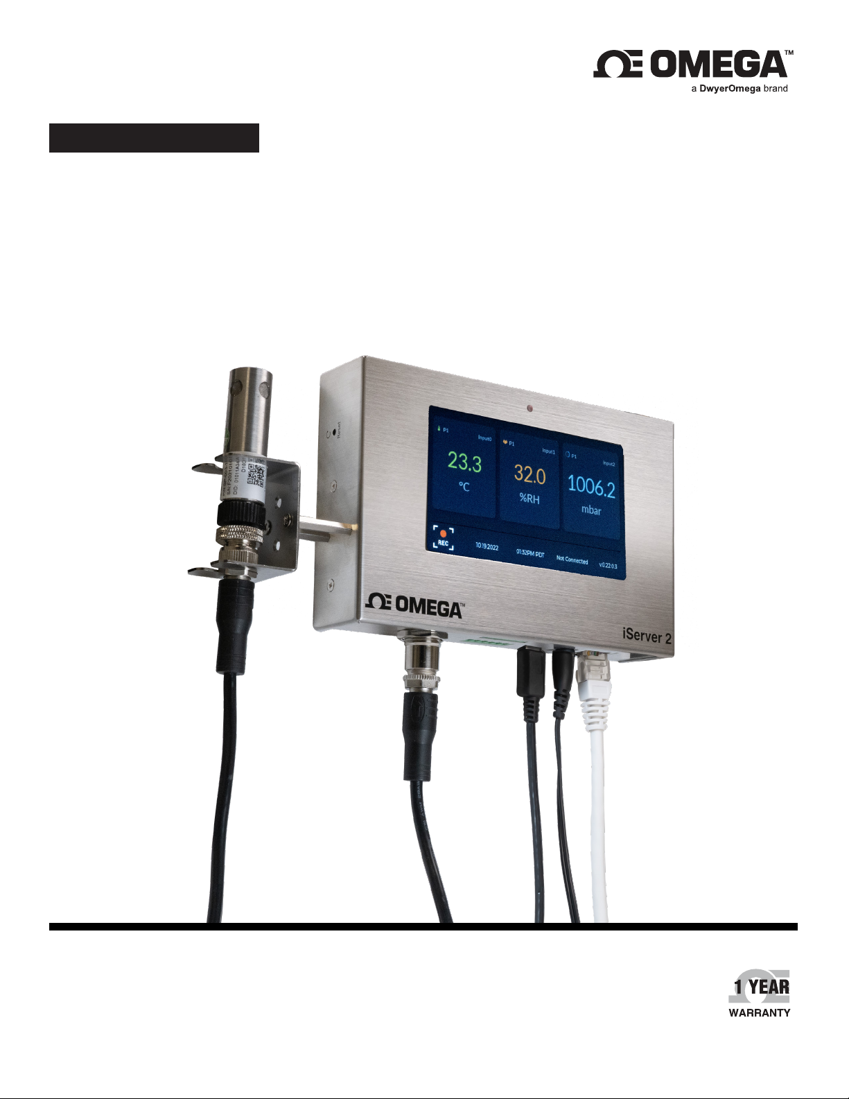
iServer 2
Virtual Chart Recorder and Webserver
omega.com | [email protected]
For latest product manuals:
omega.com/en-us/pdf-manuals
TM
Page 2

CONTACT
Omega Engineering, Inc.
omega.com/contact-us
Toll-Free:
1-800-826-6342 (USA & Canada only)
Customer Service:
1-800-622-2378 (USA & Canada only)
Engineering Service:
1-800-872-9436 (USA & Canada only)
Telephone:
(203) 359-1660
Fax:
(203) 359-7700
Email: [email protected]
For other locations visit:
omega.com/worldwide
The information contained in this document is believed to be correct,
but Omega accepts no liability for any errors it contains, and reserves
the right to alter specifications without notice.
Page 3

Table of Contents
1. Notes, Cautions, and Warnings ..................................................................................................................................... 5
1.1. Security and Public Data Access (Port Forwarding) .............................................................................................5
2. Introduction ......................................................................................................................................................................... 6
3. Hardware Setup ................................................................................................................................................................. 7
3.1. Wall Mounting and DIN Rail Assembly ........................................................................................................................7
3.2. Smart Probe Bracket Assembly ......................................................................................................................................8
4. Sensing Device Setup ...................................................................................................................................................... 9
4.1. M12 Omega Link Smart Probe Connection................................................................................................................9
4.1.1. Smart Probe SYNC Configuration ...........................................................................................................................10
4.2. Thermocouple Connection ................................................................................................................................................12
4.3. Digital I/O and Relays ........................................................................................................................................................12
4.4. Powering the iServer 2 .......................................................................................................................................................13
4.4.1. LED Status Indicator .....................................................................................................................................................13
4.4.2. 9 V Backup Battery ......................................................................................................................................................14
4.4.3. Power Over Ethernet (PoE) ........................................................................................................................................14
5. Connecting to a PC .......................................................................................................................................................... 15
5.1. Method 1 - DHCP Router Setup (Display Models Only) ........................................................................................15
5.2. Method 2 - Direct to PC Setup with an RJ45 Ethernet Cable (Display and Non-Display Models) .....15
5.3. Method 3 - Direct to PC Setup with a Micro-USB 2.0 (Display and Non-Display Models).....................16
6. Navigating the iServer 2 Web UI .................................................................................................................................. 18
6.1. Downloading the Latest iServer 2 Firmware .............................................................................................................19
6.2. Upgrading the iServer 2 with the Latest Firmware .................................................................................................21
6.3. Device Name and Sensor Firmware Information ..................................................................................................... 23
6.4. Configuring the Name of the Probe ..............................................................................................................................23
6.4.1. Omega Link Smart Probe Firmware Download and Update .......................................................................23
6.5. Network ....................................................................................................................................................................................27
6.5.1. Network Configuration ................................................................................................................................................27
6.6. Logging .....................................................................................................................................................................................28
6.6.1. Clear Log Data When Switching Smart Probe Types (Smart Probe Models Only) ............................28
6.6.2. How to Retrieve Logged Data .................................................................................................................................. 29
6.7. Events and Notifications Configuration ........................................................................................................................29
6.7.1. Buzzer .................................................................................................................................................................................30
6.7.2 . Relay 1 and Relay 2 .....................................................................................................................................................31
6.7.3. Email ...................................................................................................................................................................................32
6.7.4. Digital I/O ..........................................................................................................................................................................33
6.8. System Configuration ..........................................................................................................................................................34
6.8.1. System - Single or Dual Probe / Thermocouple Configuration ..................................................................34
6.8.2. Profile .................................................................................................................................................................................35
6.8.3. Units .................................................................................................................................................................................... 35
6.9. Channel Settings ...................................................................................................................................................................36
6.9.1 . Gain and Offset ..............................................................................................................................................................36
6.9.2. Alarm Trigger ...................................................................................................................................................................36
6.9.3. Thermocouple Configuration Interface (TC Models Only) .............................................................................37
6.10. Gauge/Chart Web UI View ..............................................................................................................................................38
Table of Contents
3
Page 4

7. Adding an iServer 2 to Omega Enterprise Gateway (OEG) ................................................................................. 39
7.1. Method 1 - DHCP Router Method...................................................................................................................................39
7.2. Method 2 - Static IP Method (Direct to PC) ...............................................................................................................40
7.3. Configuring Sensing Devices after Pairing with OEG ............................................................................................42
8. iServer 2 Modbus Holding Register Partition ............................................................................................................ 43
8.1. Holding Registers Partition ................................................................................................................................................43
8.2. Channel Value Registers ....................................................................................................................................................43
8.3. Device Meta Modbus Registers .......................................................................................................................................44
8.4. Device Configuration and Channel Configuration Registers ..............................................................................44
9. Appendix: Troubleshooting.............................................................................................................................................. 47
10. iServer 2 Specifications ................................................................................................................................................... 48
4 iServer 2 User's Manual
Page 5

1. Notes, Cautions, and Warnings
If the equipment is used in a manner not specied in this manual, the protection by the equipment may be
impaired.
Do not operate the equipment in ammable or explosive environments.
It is important to read and follow all precautions and instructions in this manual before operating or
commissioning this device as it contains important information relating to safety and EMC. Failure to follow all the
safety precautions may result in injury and/or damage to the equipment.
The following identiers provide information that is especially important to note:
Note: Provides information that is important to successfully set up and use the iServer 2.
Caution, Warning, or Important: Informs of circumstances that can affect the functionality of the instruments and
must refer to accompanying documents.
1.1. Security and Public Data Access (Port Forwarding)
The iServer 2 is designed to be used in a secure, local-area network (LAN) using a private address. Exposing
the device to public Internet trafc through Port Forwarding or similar methods may lead to signicant security
risks to the user’s network and data. OMEGA Engineering cautions users against exposing the iServer 2 to
public access through Port Forwarding.
5Notes, Cautions, and Warnings
Page 6
2. Introduction
The iServer 2 virtual chart recorder and webserver offers an intuitive way to collect and display live sensor
readings through a web-based user interface or by integrating the device into an existing Omega Link Cloud
account.
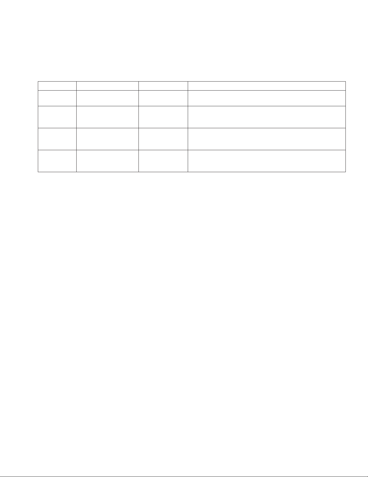
An iServer 2 unit can accept up to two Omega Link Smart Probes through an M12 connector accessory (PN#:
M12-MT-079-2F cable is required for dual Smart Probe functionality, sold separately) or two thermocouples
through thermocouple ports, depending on the model purchased.
Model No. Model Name Sensor Type Description
iS2-THB-B iServer 2 – Basic Smart Probe
iS2-THB-ST iServer 2 – Standard Smart Probe
iS2-THB-DP
iS2-THB-DTC
The iS2-THB-ST, iS2-THB-DP, and iS2-THB-DTC feature 2 congurable digital I/O and relay ports. These can be
used for a myriad of applications including driving relays or physical alarms. The iServer 2 can also be utilized
as an edge controller, with autonomous independent decision-making capabilities to generate local alarms or
provide control outputs based on sensor inputs. A fully congurable alarm system is available in the web UI to
create events and thresholds that will trigger a notication should those conditions be met. A modern notication
system allows users to be notied via email or text. Omega Link compatible devices, such as the iServer 2, can
be added to an existing Omega Link Ecosystem to provide data anytime, anywhere, by rst adding the iServer 2
device to an Omega Enterprise Gateway account and then adding that account to the Omega Link Cloud.
iServer 2 – Deluxe
Probe
iServer 2 – Deluxe
Thermocouple
Smart Probe
Thermocouple
Virtual chart recorder and webserver with M12 Smart
Probe compatibility, 1x USB port
Virtual chart recorder and webserver with M12 Smart
Probe compatibility, 4.3” LCD, 1x USB Port, Digital I/O
and Relays
Virtual chart recorder and webserver with M12 Smart
Probe compatibility, 4.3” LCD, 1x USB Port, Digital I/O
and Relays, Power over Ethernet
Virtual chart recorder and webserver with 2x
Thermocouple ports, 4.3” LCD, 1x USB Port, Digital I/O
and Relays, Power over Ethernet
6 iServer 2 User's Manual
Page 7
3. Hardware Setup
The iServer 2 can be assembled to be mounted in a variety of ways. Refer to the following sections for
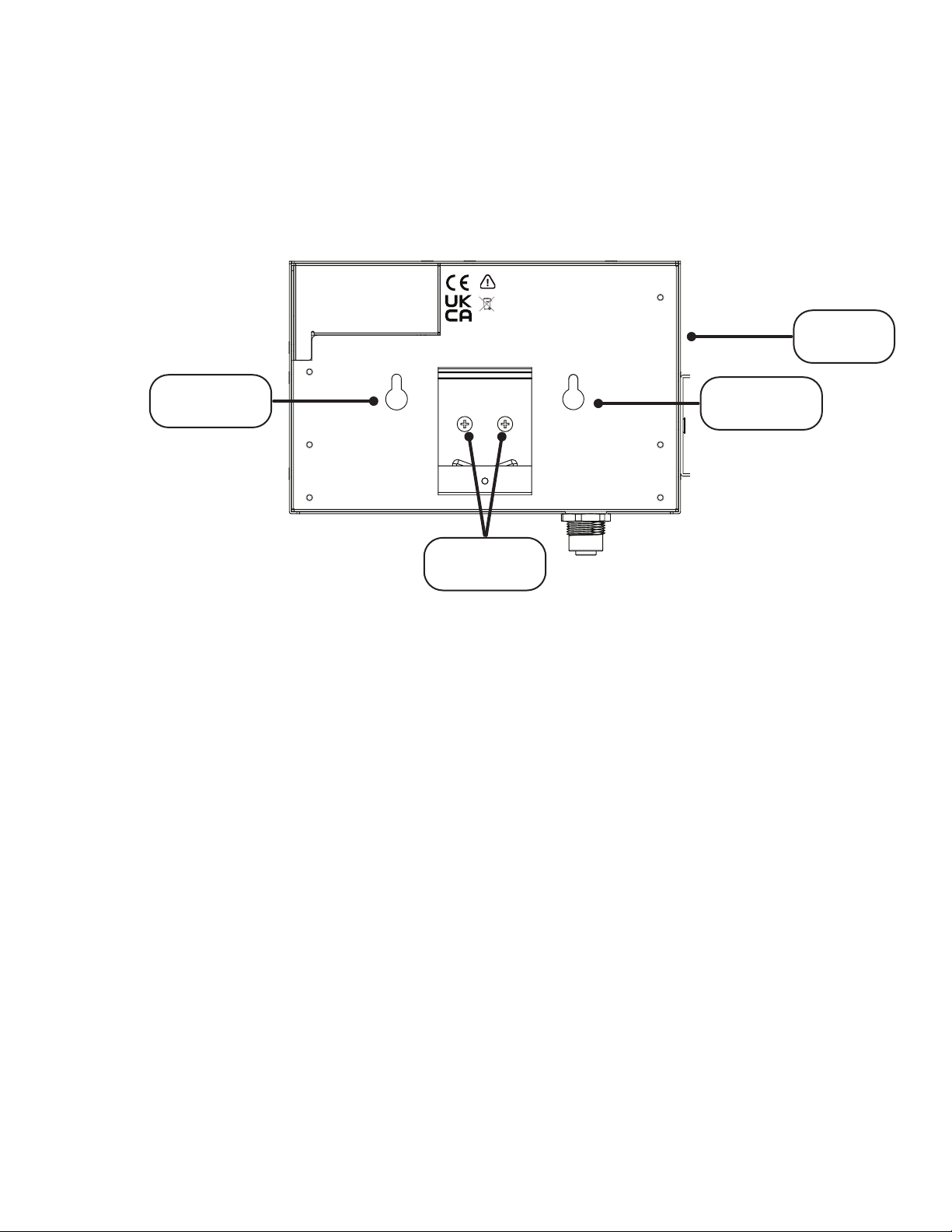
instructions on how to assemble the hardware for different applications. The physical reset button is located on
the left side of the iServer 2 unit as shown in the gure below.
3.1. Wall Mounting and DIN Rail Assembly
All models of the iServer 2 are wall-mountable and come with an optional DIN rail bracket. The distance
between the two wall-mounting screw holes is 2 ¾” (69.85 mm). To attach the DIN rail bracket hardware,
locate the two screw holes on the underside of the unit and use the two included screws to secure the
bracket in place as indicated in the gure below:
CAUTION: Risk of danger. This device is marked with the international Caution
symbol. It is important to read the Setup Guide before installing or
commissioning this device as it contains important information relating to
safety and EMC.
Use Copper Conductors only for Power Connections.
FCC: This device complies with Part 15, Subpart B, Class B of the FCC rules.
Reset
Button
Wall-mount
screw hole
Wall-mount
screw hole
DIN rail
bracket
Figure 1: DIN rail bracket and wall-mount screw hole locations
7Hardware Setup
Page 8
3.2. Smart Probe Bracket Assembly
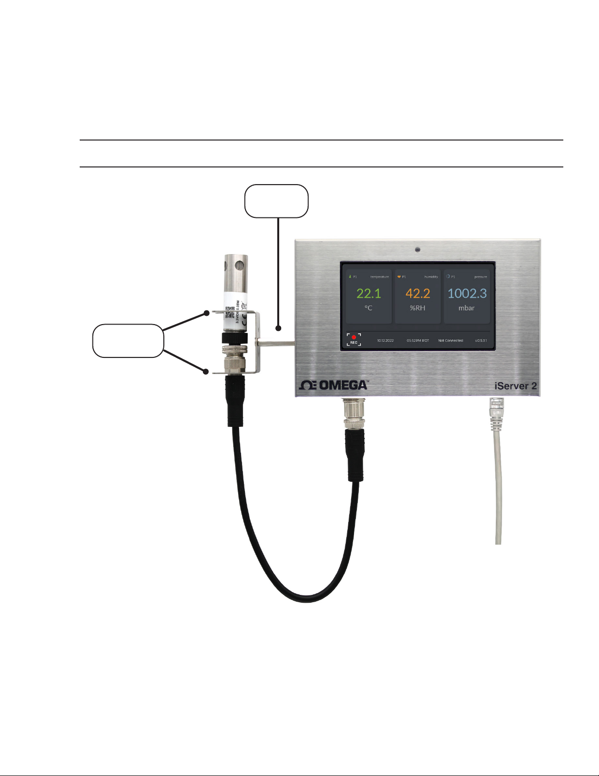
The iS2-THB-B, iS2-THB-ST, and iS2-THB-DP come with a Smart Probe Bracket and stand-off extenders to
mount the Omega Link Smart Probe 1 ½” away from the unit.
Step 1: Locate the two screw holes on the left side of the unit and screw in the standoff extenders. For
accurate sensor readings, the standoff extenders are highly recommended.
Step 2: Align the screw holes of the smart probe bracket with the standoff extenders and use the two
included screws to secure the bracket in place as indicated in the gure below.
Note: Ensure the wider end of the bracket opening is pointing upwards.
Standoff
Extenders
Smart
Probe Bracket
Figure 2: iServer 2 unit with standoff extenders and smart probe bracket attached
8 iServer 2 User's Manual
Page 9
4. Sensing Device Setup
The sensing device setup will vary for the smart probe and thermocouple variants of the iServer 2.
M12 Omega Link Smart Probes Models
• iS2-THB-B
• iS2-THB-ST
• iS2-THB-DP
Thermocouple Model
• iS2-THB-DTC
Refer to either the section titled 4.1 M12 Omega Link Smart Probe or 4.2 Thermocouple Connection to complete
the sensing device setup.
4.1. M12 Omega Link Smart Probe Connection
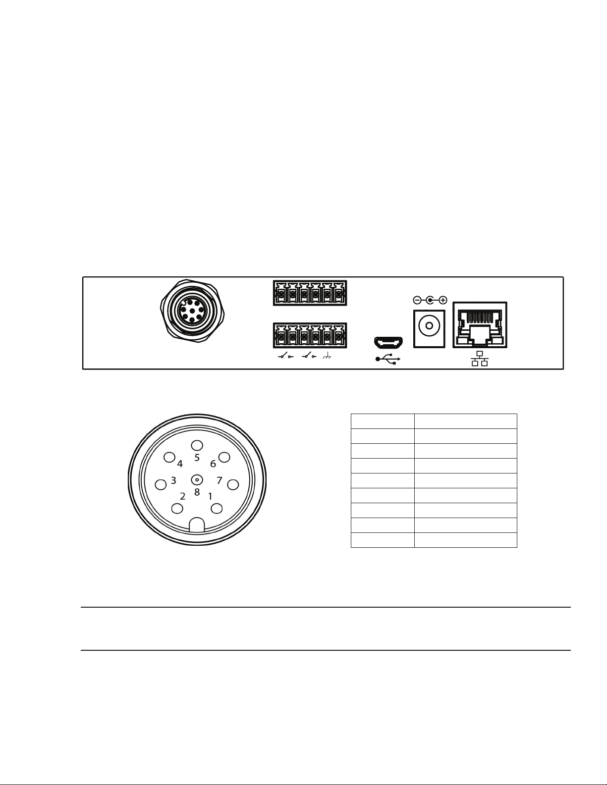
The iS2-THB-B, iS2-THB-ST, and iS2-THB-DP can accept up to two Omega Link Smart Probes through an M12
connector (PN#: M12-MT-079-2F cable is required for dual Smart Probe functionality, sold separately). Begin
by plugging in the included Smart Probe to the iServer 2 unit using the included M12 8-pin extension cable.
Take note of the keyway on the connectors.
PoE
DI2+
DI2-
DI1+
DI1-
DO+
DO-
Smart Probe (M12)
R2 R1
Figure 3: iS2-THB-DP with M12 Smart Probe connector
+12 V
DC 12 V
Pin Description
Pin 1 I2C-2_SCL
Pin 2 Interrupt Signal
Pin 3 I2C -1 _ S CL
Pin 4 I2C-1_SDA
Pin 5 Shield Ground
Pin 6 I2C-2_SDA
Pin 7 Power Ground
Pin 8 Power Supply
Figure 4: M12 8-pin female connector for iServer 2 front view and pin layout
Important: It is recommended that users access the digital I/O provided by the iServer 2 instead of the
connected Smart Probe. Using the digital I/O of the Smart Probe may cause device operation errors. See the
following section titled 4.3 Digital I/O and Relays.
9Sensing Device Setup
Page 10
4.1.1. Smart Probe SYNC Configuration
Omega Link Smart Probes can be congured using Omega’s free SYNC conguration software when
connected to a Windows PC using an Omega Link Smart Interface such as the wired IF-001 or wireless
IF-006. When the Omega Link Smart Probe and Smart Interface are connected to a Windows PC running
SYNC, users may click the Refresh button on the SYNC interface to auto-detect the connected Smart
Probe. Once the device has been detected, the user will be presented with the available conguration
options.
4.1.1.1. Important Smart Probe Digital I/O Configuration
To ensure proper operation between the iServer 2 and connected Omega Link Smart Probe, Smart
Probes that offer Digital I/O (DIO) must have the Digital I/O set to Active Low at the Smart Probe
level. Setting the Omega Link Smart Probe Digital I/O to Active Low can be completed using one of
the rst two methods listed below:
Method 1: The factory default setting to the Digital I/O is Active Low. If the user has not changed the
Digital I/O settings, there is no change needed. If the Digital I/O has been changed, a factory reset
can be used to set the Digital I/O back to the default Active Low.
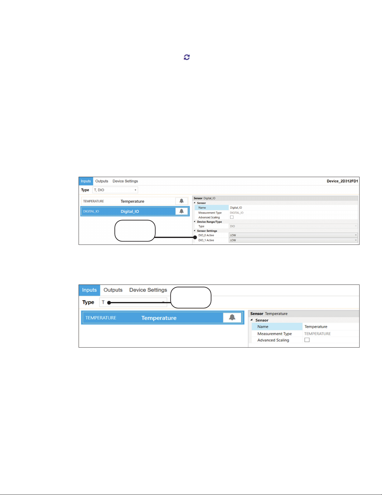
Method 2: Using SYNC conguration software, the user may navigate to the Inputs tab of the
connected Smart Probe and manually change the Digital I/O of the Smart Probe to Active Low as
shown below.
Set to
“Low”
Figure 5: SYNC configuration of smart probe digital I/O set to Low
Method 3: Using SYNC Conguration software, the user may navigate to the Type dropdown
associated with the Smart Probe and select a Type that does not include DIO as shown below.
Excludes
“DIO”
Figure 6: SYNC configuration smart probe type excludes DIO
10 iServer 2 User's Manual
Page 11
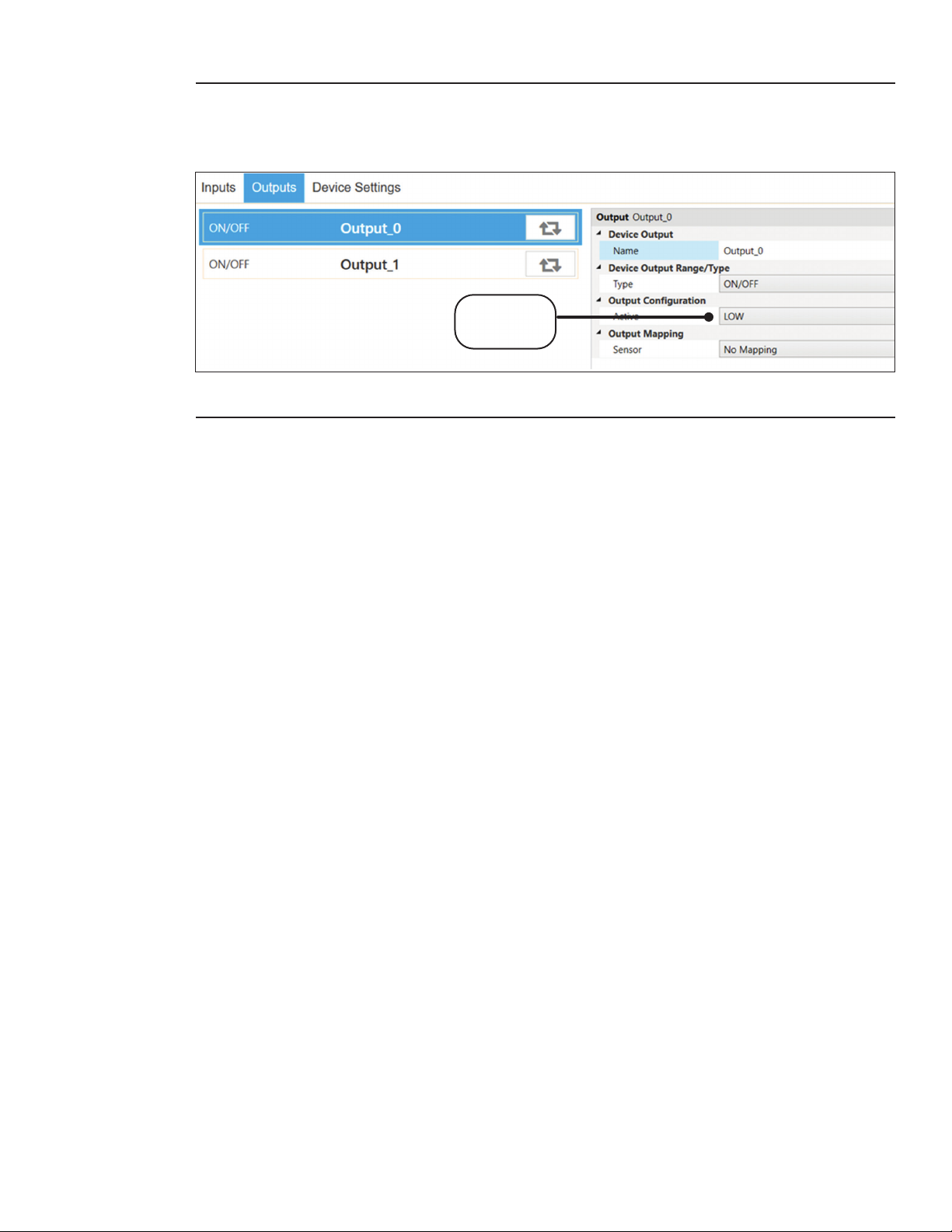
Important: If the user proceeds with a method that requires the DIO to be manually changed in the
SYNC Inputs tab (Method 2 and Method 3), the user must also ensure the DIO settings in the Output
tab to be set to Active Low for BOTH Outputs. A Factory Reset also sets the Output DIO to Active
Low by default.
Output
set to “Low”
Figure 7: SYNC configuration smart probe output set to Low
11Sensing Device Setup
Page 12
4.2. Thermocouple Connection
C
The iS2-THB-DTC can accept up to two thermocouples. Refer to the thermocouple connector diagram below
to properly connect your thermocouple sensor to the iServer 2 unit.
PoE
DI2+
DI2-
DI1+
DI1-
DO+
DO-
TC2- TC2+ TC1- TC1+
Important: Currently there is Cold Junction Calibration menu available for B-type thermocouples. To
compensate for the B-type thermocouple wire error, users may congure the Offset (b) and Gain (m) available
in the sensor channel set tings menu. Refer to section 6.9.1 Gain and Offset for more information.
4.3. Digital I/O and Relays
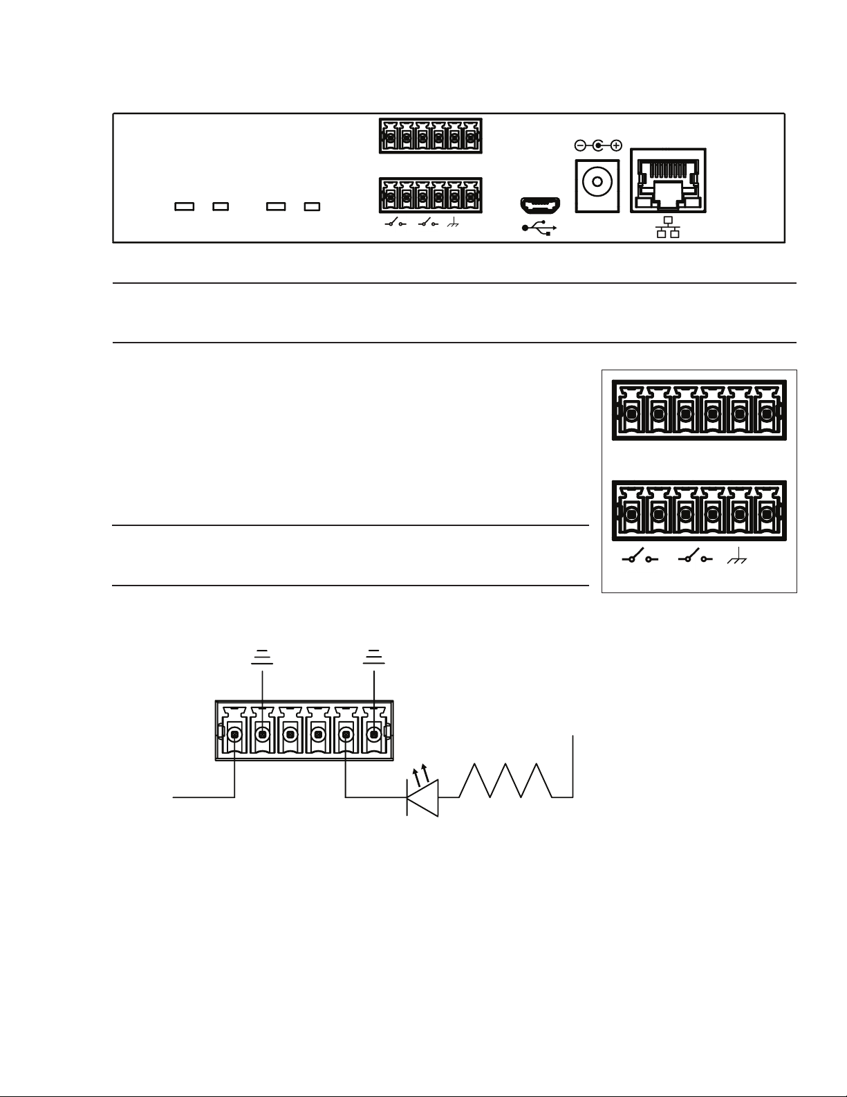
Use the provided terminal block connectors and the connector diagram in
Figure 9 to wire Digital I/O and Relays to the iServer 2.
The DI connections (DI2+, DI2-, DI1+, DI1-) accept a 5 V (TTL) input.
The DO connections (DO+, DO-) require an external voltage and can support
up to 0.5 amps at 60 V DC.
The Relays (R2, R1) can support a load of up to 1 amp at 30 V DC.
Important: When wiring the included terminal block connectors to access the
digital I/O, alarms, or relays, it is recommended that users ground the unit by
connecting a wire to the chassis ground of the connectors shown in Figure 9.
Below is an example of an LED circuit connected to the digital inputs and
outputs.
R2 R1
Figure 8: iS2-THB-DTC with thermocouple connectors
+12 V
DC 12 V
DI2+
DI2-
DI1+
DI1-
DO+
DO-
R2 R1
Figure 9: iServer 2 - Deluxe digital
I/O and relays terminal block
+12 V
DI2+
DI1+
DI1-
DO+
EXT +5V
DI2-
DO-
TRL +5V
Figure 10: iServer 2 sample LED circuit with digital input and output
Further conguration regarding Normally Open/Normally Closed Initial State or Triggers can be completed in
the iServer 2 web UI. For more information, refer to sections 6.7.2 Relay 1 and Relay 2 or 6.7.4 Digital I/O.
12 iServer 2 User's Manual
Page 13
4.4. Powering the iServer 2
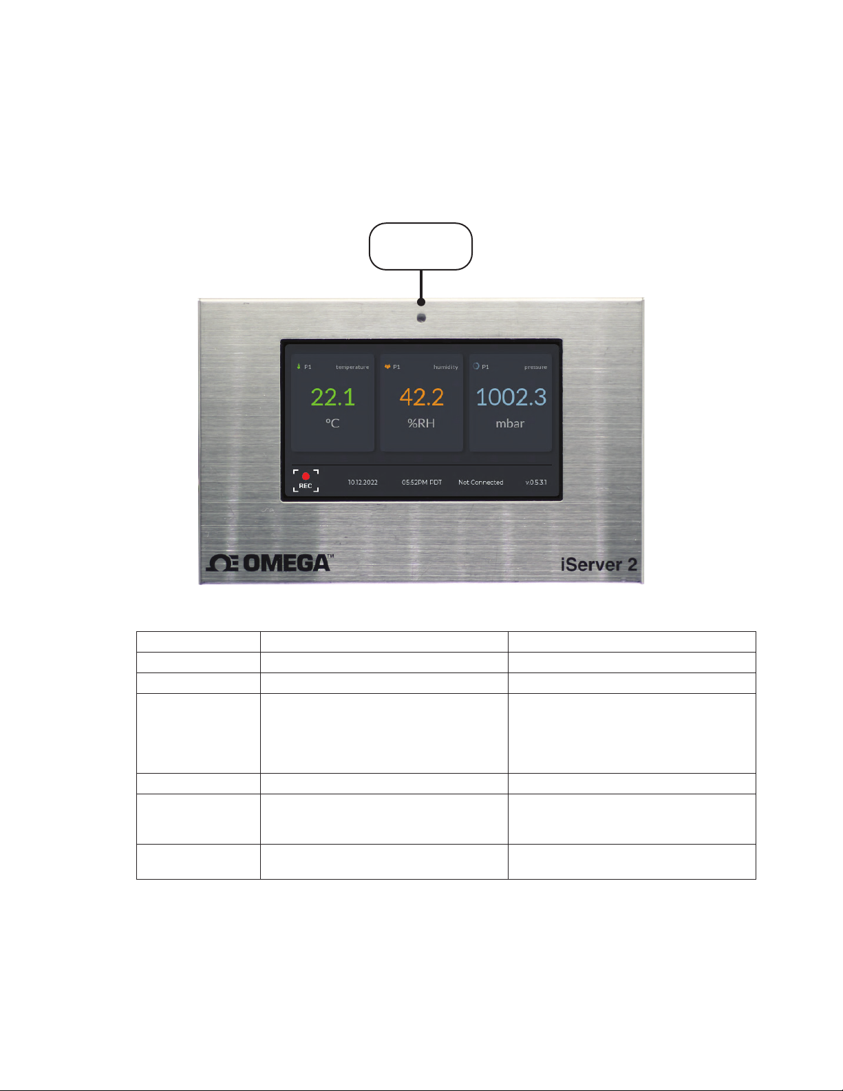
All iServer 2 variants come with a DC power supply, international power supply adapters, and a 9 V battery.
Models that offer Power over Ethernet can be powered with a network switch that supports PoE or a PoE
injector (sold separately). Once the device is powered on, fully booted up, and the appropriate sensor is
connected, readings will appear on the display. To power the iServer 2 using the DC power supply, plug in
the power supply to the DC 12 V port located on the iServer 2. For instructions on how to power the iServer 2
through the Power over Ethernet feature, refer to section 4.4.3 Power Over Ethernet.
4.4.1. LED Status Indicator
Refer to the following LED Status Indicator table to identify the different iServer 2 behaviors and statuses.
LED Status
Indicator
Figure 11: LED status indicator
LED Color Status Description
OFF No Power No power applied.
Red (Blinking) System Boot System rebooting.
Press and hold the reset button for
10 seconds to reset the iServer 2 to
Red (Solid) Factory Reset
Green (Solid) Internet Connection Detected iServer 2 is connected to the Internet.
Green (Blinking) Firmware Updating
Amber (Solid) No Internet Connection Detected
factory default.
WARNING: The factory reset will reset
all stored data and conguration.
Firmware update in progress.
WARNING: Do not unplug power
while update is in progress.
iServer 2 is not connected to the
Internet.
13Sensing Device Setup
Page 14
4.4.2. 9 V Backup Battery
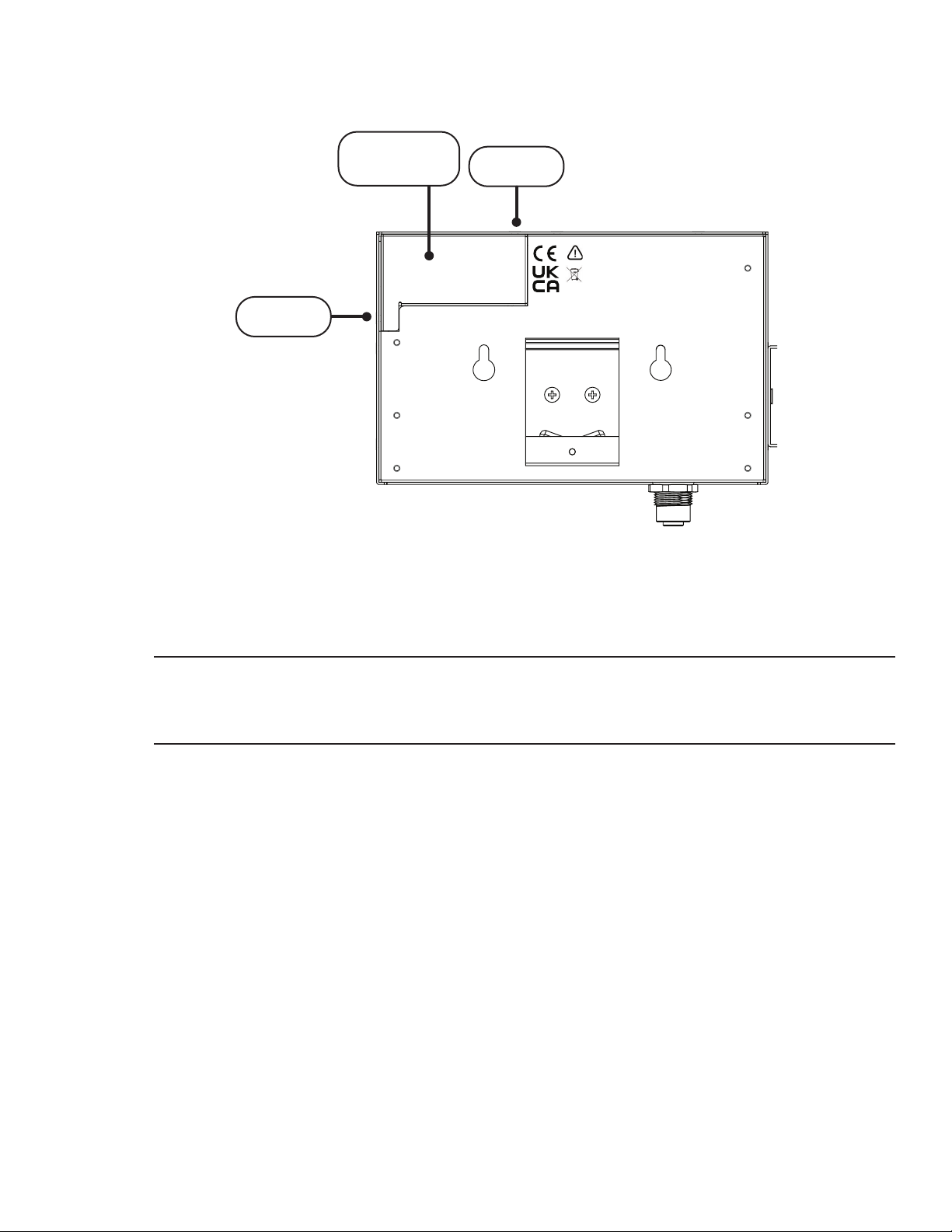
To access the 9 V battery compartment, remove the two screws indicated in the gure below and gently
pry open the battery compartment.
Battery
Compartment
Screw 1
CAUTION: Risk of danger. This device is marked with the international Caution
symbol. It is important to read the Setup Guide before installing or
commissioning this device as it contains important information relating to
safety and EMC.
Use Copper Conductors only for Power Connections.
FCC: This device complies with Part 15, Subpart B, Class B of the FCC rules.
Screw 2
Figure 12: 9 V battery installation
Insert the 9-volt battery and secure the screws again. The battery will serve as a backup power source
in case of a power outage. A fully charged 9 V battery will allow the iServer 2 to continue logging up to
10,000 data points for a period of 96 hours.
Important: When the 10 000 logged data points have been exceeded while running on the backup
battery, the oldest logged data point on the Smart Probe will be overwritten starting from the oldest
data point saved on the Smart Probe. A logging interval of at least 35 seconds or longer will prevent the
overwriting of data during the 96 hour period the battery is in use.
4.4.3. Power Over Ethernet (PoE)
The iS2-THB-DP and iS2-THB-DTC both offer a Power over Ethernet (POE) feature that provides the device
with sufcient power to operate when connected to a PC or router that supports Power over Ethernet. Use
an RJ45 Ethernet cable to connect the output port of the PoE Injector to the iServer 2. Then use a second
RJ45 Ethernet cable to connect the input port of the PoE Injector to a standard router or PC in conjunction
with the PoE injector. When the assembled PoE Injector is plugged into a power outlet, the device will
power on.
14 iServer 2 User's Manual
Page 15
5. Connecting to a PC
To connect your iServer 2 unit to your PC, follow the instructions for one of the three setup methods listed below.
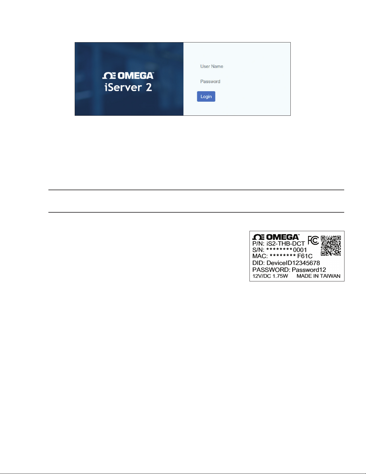
Figure 13: iServer 2 login page
A successful setup will result in the user accessing the webserver login page. Refer to the applicable connection
method below:
5.1. Method 1 - DHCP Router Setup (Display Models Only)
Connect your iServer 2 directly to a DHCP-enabled router using an RJ45 cable. On the display model, the
assigned IP address will appear on the lower right of the device display. Open a web browser and navigate
to the assigned IP address to access the web user interface (UI).
Important: For non-display models, the user will need to check the router’s client IP table to connect via
DHCP or connect using Method 2 or 3.
5.2. Method 2 - Direct to PC Setup with an RJ45 Ethernet Cable (Display and Non-Display Models)
Connect your iServer 2 directly to your PC using an RJ45 Ethernet cable.
Identify the MAC Address assigned to your iServer 2 by checking the label
on the backside of the device.
Open a web browser and enter the following URL to access the web UI:
http://is2-omegaXXXX.local
(the XXXX should be replaced by the last 4 digits of the iServer unit MAC
address)
Figure 14: iServer 2 label showing
unique MAC address
15Connecting to a PC
Page 16
5.3. Method 3 - Direct to PC Setup with a Micro-USB 2.0 (Display and Non-Display Models)
Important: Administrator access to the PC may be required to change the PC Network Properties. The default
static IP for connections through USB is: 192.168 .3.2 00. If the user is unable to access the iServer 2 webserver
UI, the Bonjour Service may need to be installed. The service can be downloaded from the following URL:
https://omegaupdates.azurewebsites.net/software/bonjour
To begin, connect the iServer 2 directly to the PC using a micro-USB 2.0 cable.
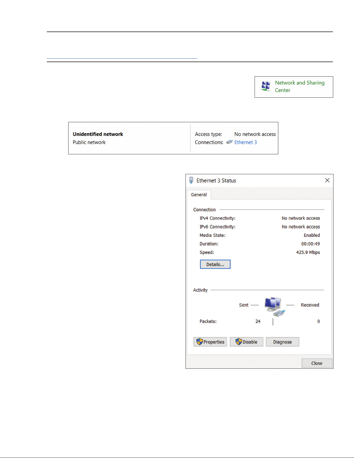
Step 1: Navigate to the Windows Control Panel and click Network and Sharing
Center.
Figure 15: Windows Control Panel
Step 2: Click the Unidentied Network Connection.
Figure 16: Network and Sharing Center - Unidentified Network
Step 3: Click Properties.
Network and Sharing Center
Figure 17: Unidentified Network Status
16 iServer 2 User's Manual
Page 17
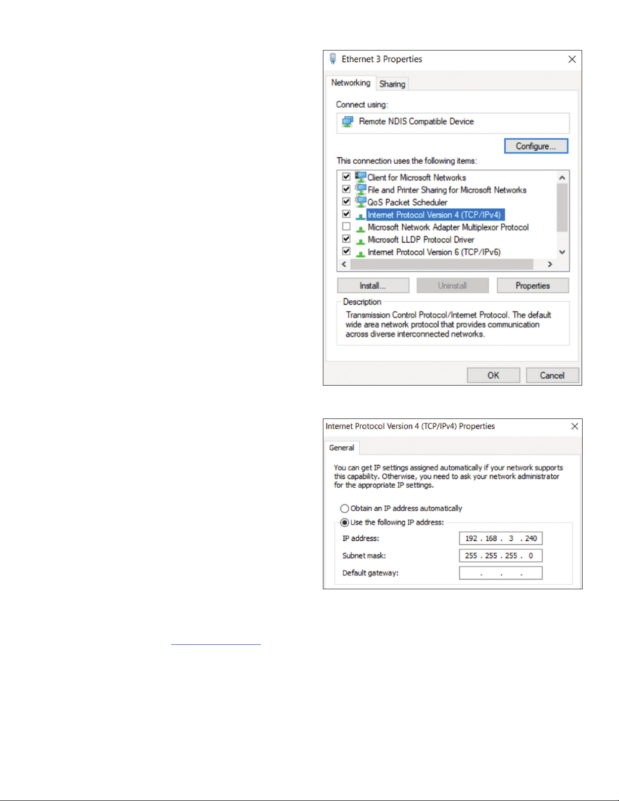
Step 4: Click Internet Protocol Version 4 (TCP/IPv4)
to highlight the selection and then click
Properties.
Figure 18: Unidentified Network Properties
Step 5: Fill out the eld for the IP address with the
following:
192.168.3.XXX
(the XXX can be any value that is NOT 200)
Fill the Subnet Mask eld with the following:
255.255.255.0
Figure 19: TCP/IPv4 and subnet mask properties for micro USB
2.0 connection
Click OK to nalize and then reboot the PC. Open a web browser and navigate to the following address to
access the web UI: ht tp://192 . 168. 3 . 2 0 0
17Connecting to a PC
Page 18
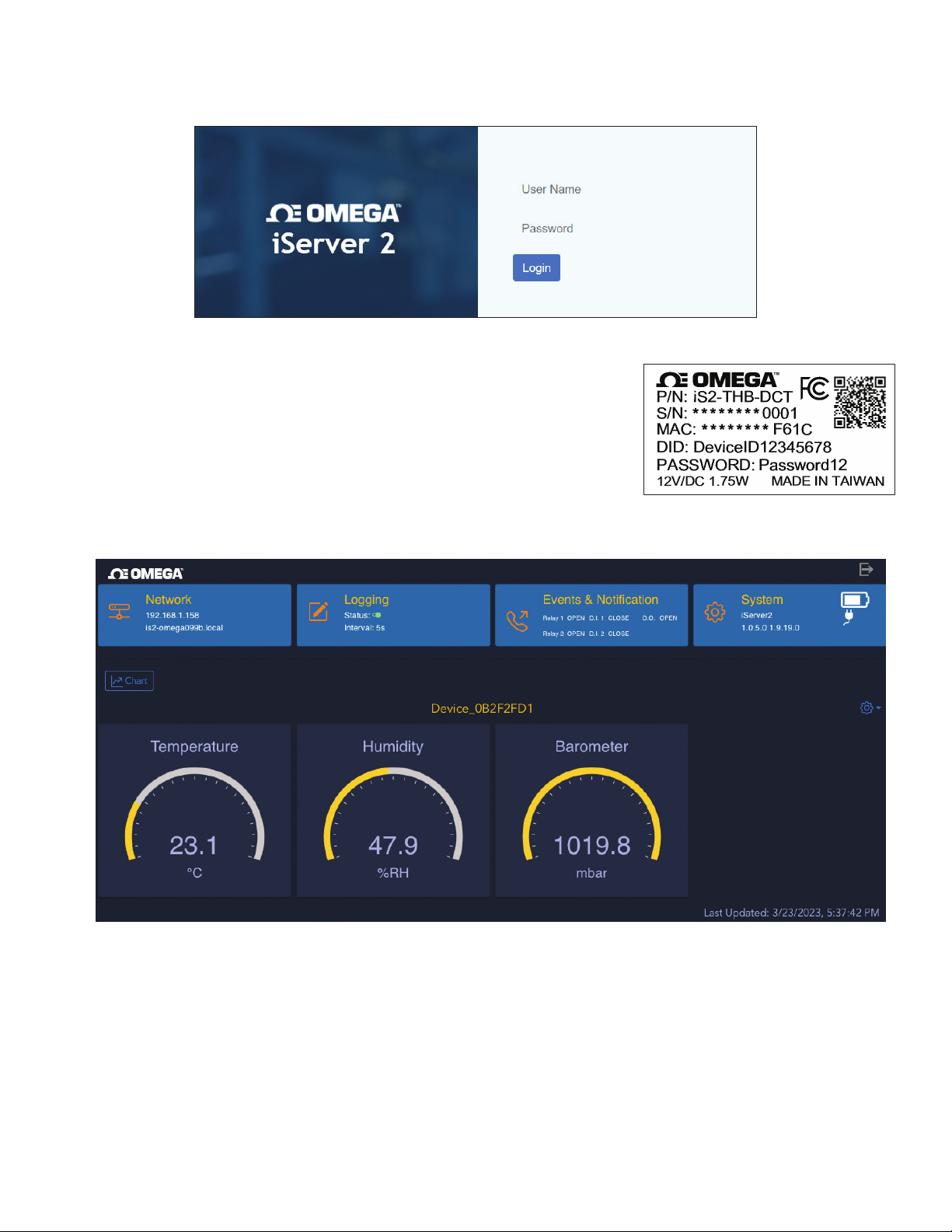
6. Navigating the iServer 2 Web UI
When the iServer 2 has been properly connected to a PC and the user has accessed the webserver login by
following one of the methods in the previous section, they will be presented with the login page.
Figure 20: iServer 2 login page
Users who are signing in to the web UI for the rst time, or if the login
information has not been changed, can type the following information to
login:
Username: admin
The password is provided on a label located on the back of the physical
unit. Once logged in, the web UI will display the sensor readings as different
gauges.
Figure 21: iServer 2 label showing unique
MAC address
Figure 22: iServer 2 web UI sensor readings homepage - Gauge View
From the web UI, users can congure Network settings, Logging set tings, Events & Notications, and System
settings.
18 iServer 2 User's Manual
Page 19
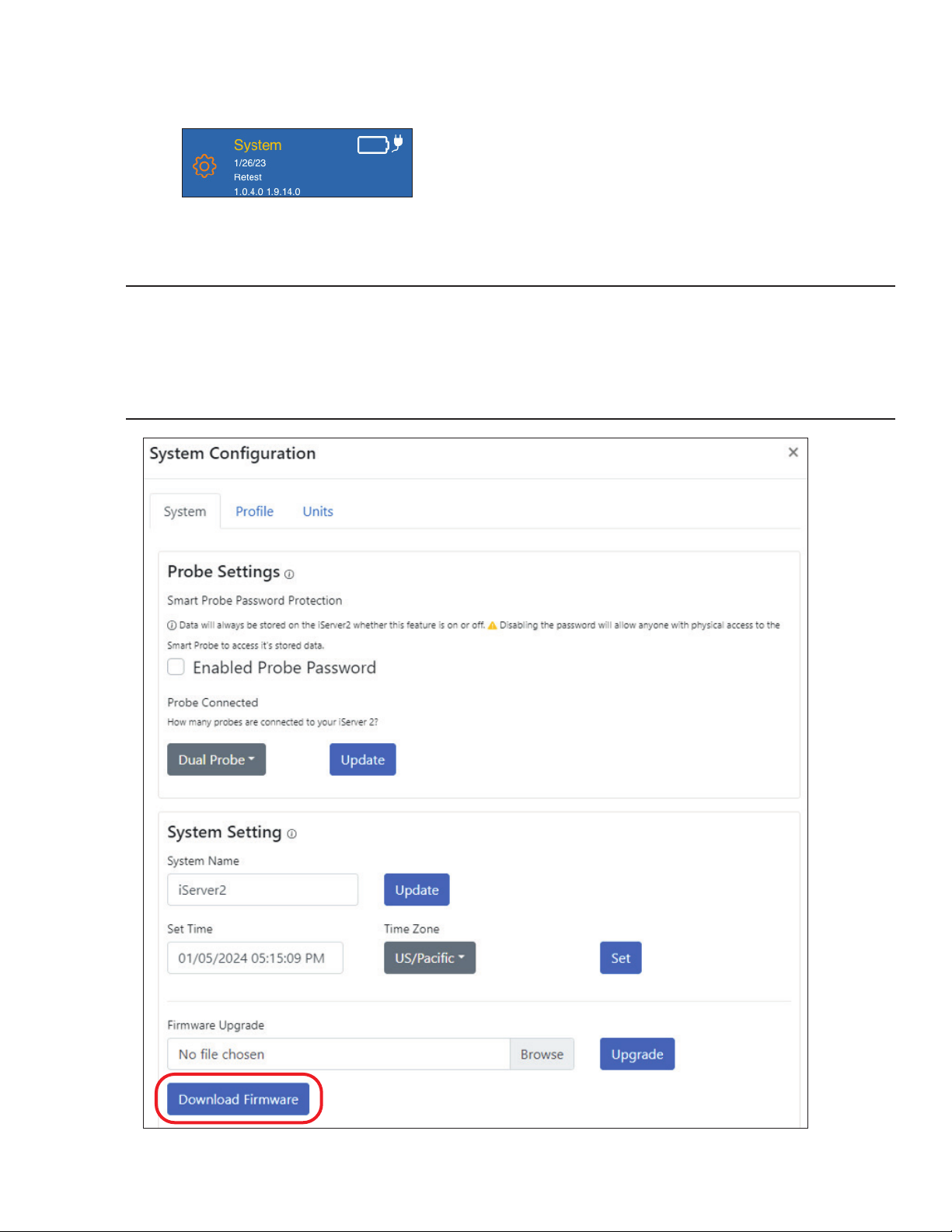
6.1. Downloading the Latest iServer 2 Firmware
Step 1: From the iServer 2 webserver interface, click the System tab on the upper right of the screen. A
System Conguration pop-up window will appear.
Figure 23: Webserver UI System tab
Step 2: Click the Download Firmware button. Note that two download links should appear.
Important: iServer 2 devices require two rmware les to complete the rmware upgrade process: a .bin and
.hex le. Both download URLs should appear when the user clicks the Download Firmware button.
iServer 2 devices that are using an older rmware version may only have one download link appear at a
time. In case only one rmware link appears, proceed to download and install the le according to the steps
outlined in the rest of this section and the following section, then clear the web browser cache being used,
and nally repeat the process starting from Step 2 of this section, until the iServer 2 rmware is up-to-date.
Figure 24: System Configuration pop-up window, Download Firmware button
19Navigating the iServer 2 Web UI
Page 20
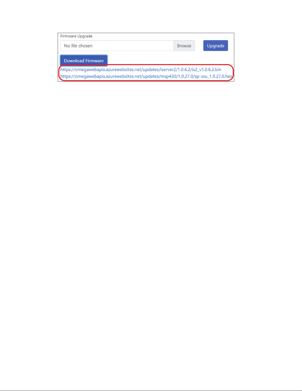
Step 3: Click on both download links that appear to download both rmware upgrade les. Note that both
les are necessary to successfully complete the rmware upgrade.
Figure 25: iServer 2 firmware download links
20 iServer 2 User's Manual
Page 21
6.2. Upgrading the iServer 2 with the Latest Firmware
The instructions below will outline the steps necessary to perform the iServer 2 rmware upgrade process
using the recently downloaded rmware les.
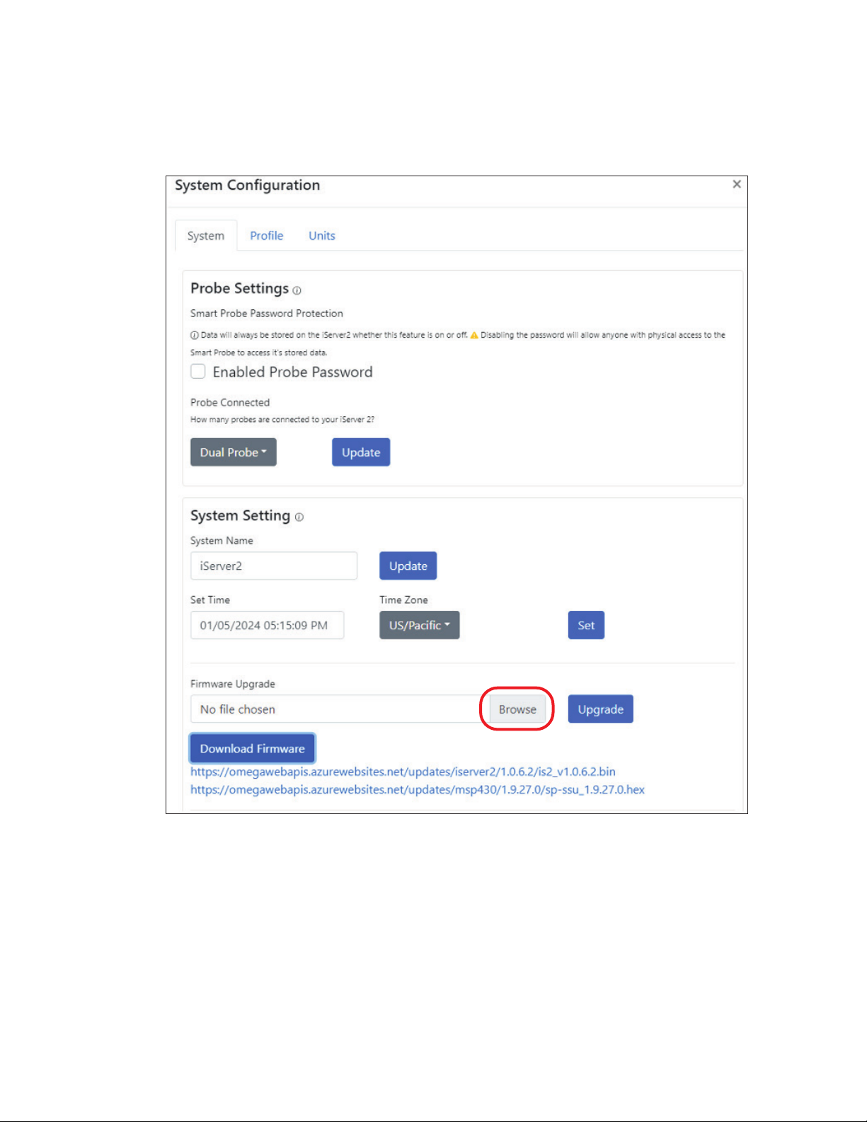
Step 1: From the System tab in the iServer 2 webserver interface, click on the Browse button to locate the rst
rmware le that will be used in the upgrade. The user may choose to start with either rmware le
(.bin or .hex) as the order does not matter.
Figure 26: System Configuration pop-up window, Browse button
21Navigating the iServer 2 Web UI
Page 22
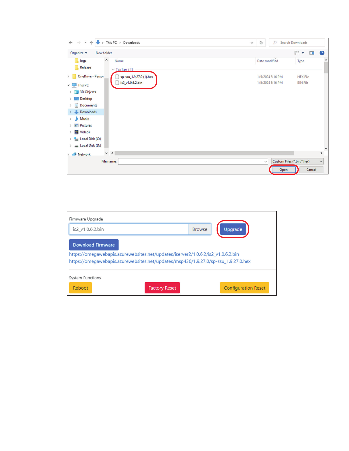
Step 2: A pop-up window will appear allowing the user to select one of the recently downloaded rmware
les to be used for the upgrade. Click Open to nalize the selection.
Figure 27: Firmware file selection for iServer 2 upgrade
Step 3: With one of the rmware les selected, click the Upgrade button. The iServer 2 will begin the upgrade
process and will reboot when the process is complete.
Figure 28: System Configuration Upgrade button
Step 4: Repeat the process starting from Step 1 of this Upgrade the iServer 2 with the Latest Firmware
section with the second rmware (.bin or ,hex, depending on which was used for the upgrade rst).
22 iServer 2 User's Manual
Page 23
6.3. Device Name and Sensor Firmware Information
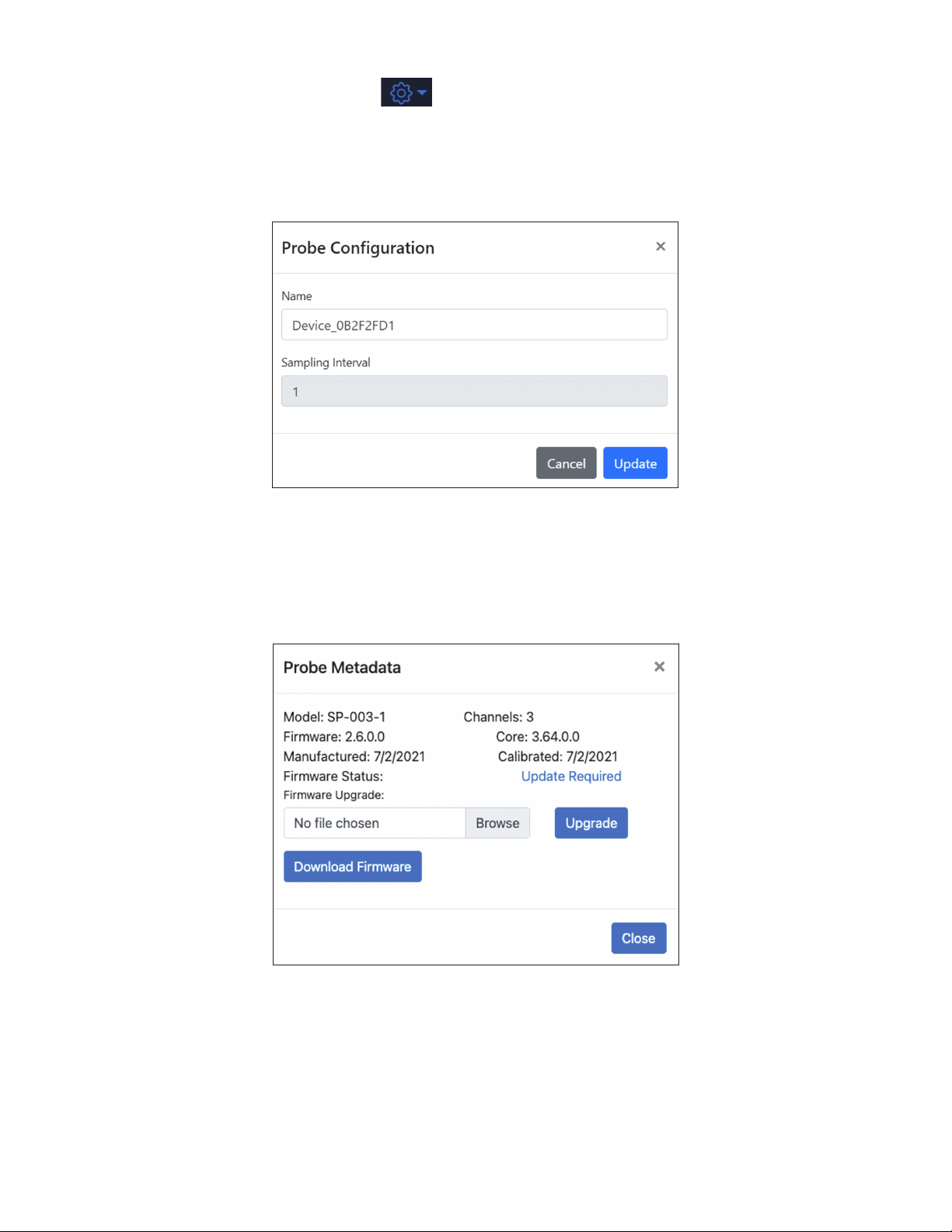
While in Gauge View, the Gear Icon under the System Tab will allow users to congure the name of
the iServer 2 device and view the current rmware, available channels, and core version number. When the
Gear icon is clicked, the user will be able to choose between Congure and Information.
6.4. Configuring the Name of the Probe
From the Congure window, users may update the sensor device name as it appears in the web UI.
Figure 29: Probe name configuration
6.4.1. Omega Link Smart Probe Firmware Download and Update
From the Information window, users can check online for the latest rmware version of their Smart Probe
and download it. If a rmware update is available, the user will be able to download it directly from the
clickable Update Required or Download Firmware link that appears below.
Figure 30: Smart Probe firmware update available
23Navigating the iServer 2 Web UI
Page 24
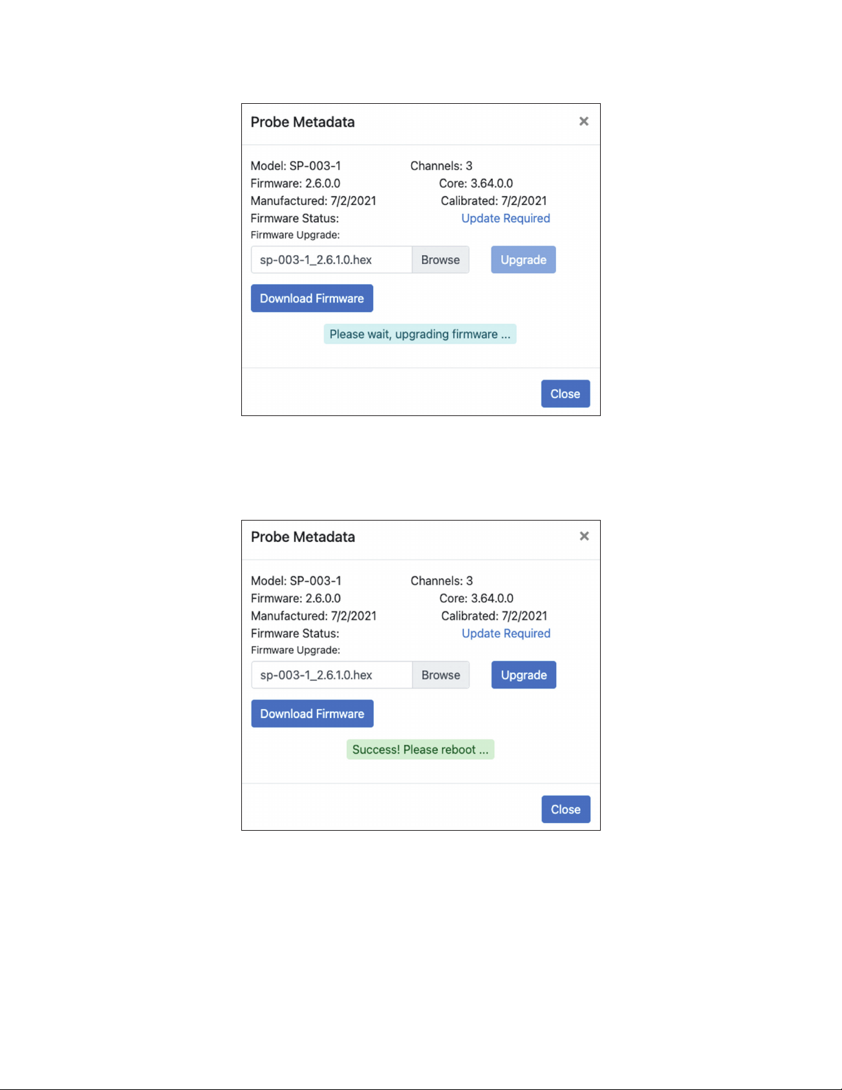
Once the rmware update le has been downloaded to the PC, the user will need to click Browse and
select the recently downloaded rmware le. Once the le has been selected, click Upgrade to start the
rmware update process.
Figure 31: Smart Probe update in progress
When the Smart Probe rmware update is successful, a success message will briey appear and instruct
the user to reboot the device. At this point, the user may reboot the device and refresh the iServer 2 web
UI page to sign back into the web UI and view the updated probe information.
Figure 32: Successful smart probe firmware update
24 iServer 2 User's Manual
Page 25
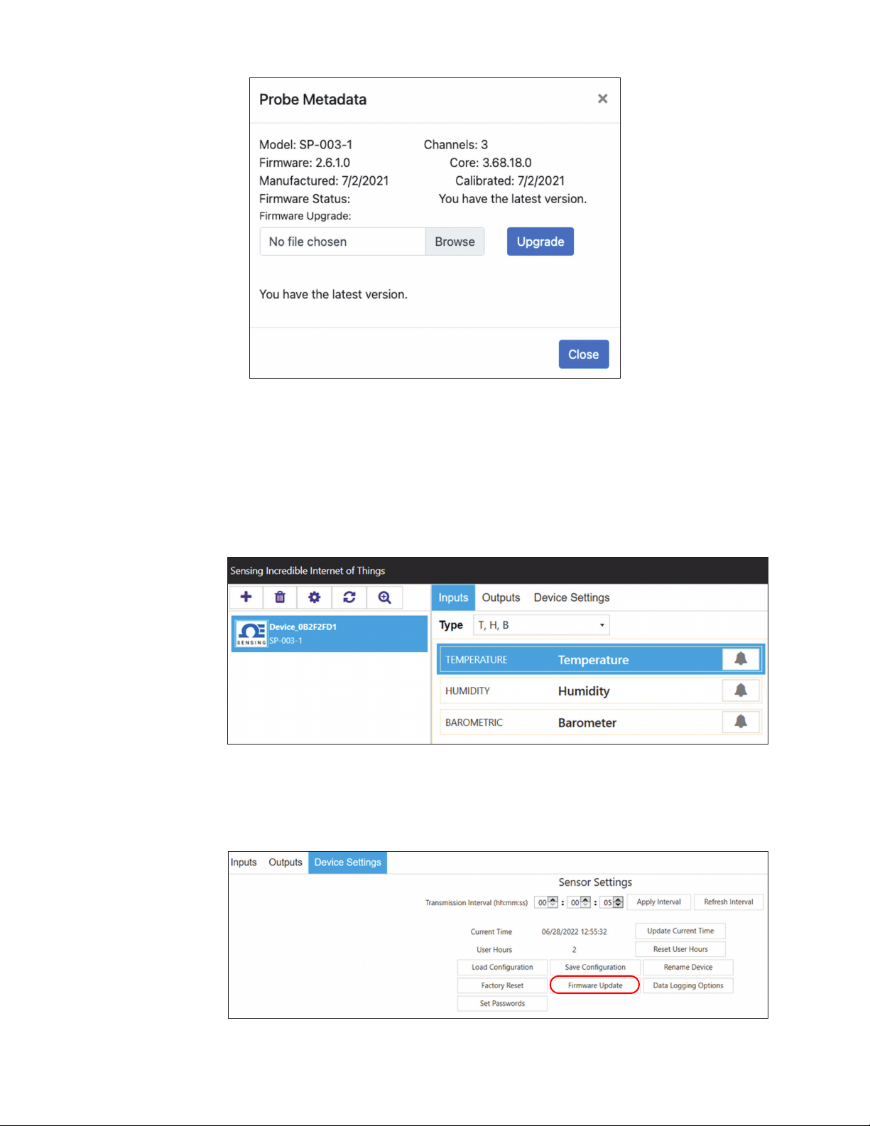
If the probe is up to date and no update is required, the web UI will state that the latest rmware is being
used.
Figure 33: Confirmation that the latest smart probe firmware is
installed
6.4.1.1. Advanced Smart Probe Configuration and Alternative Firmware Update with SYNC
Omega Link Smart Probe rmware updates can also be completed through Omega’s SYNC
conguration software. The rmware must still be downloaded from the iServer 2 web UI. Simply
launch the software on a PC with an open USB port, and connect the Smart Probe to the PC using
an Omega Link Smart Interface, such as the IF-001 or IF-006-NA.
Figure 34: SYNC auto-detects smart probes connected through an Omega Smart Interface like
IF-001
SYNC will automatically detect the connected Smart Probe and will display the device Inputs tab.
Click the Device Settings tab and click the Firmware Update button.
Figure 35: SYNC Device Settings and Firmware Update button
25Navigating the iServer 2 Web UI
Page 26
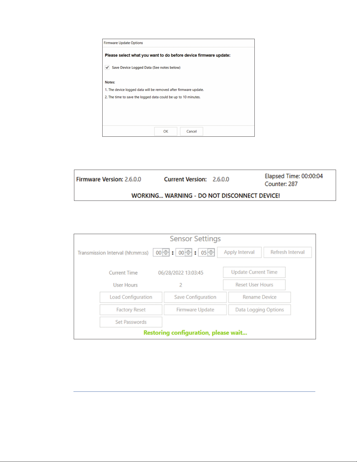
The user will be given the option to save any previously logged device data, however, users should
note this option may take up to 10 minutes to complete.
Figure 36: Firmware update process
Open the update le from the PC File Explorer containing the latest rmware for your Smart Probe
to begin the rmware update process.
Figure 37: DIN rail bracket and wall-mount screw hole locations
When the update is complete, the user will need to conrm on screen that the device will be power
cycled. SYNC will reopen the Inputs UI tab once the process is complete.
Figure 38: After the update process, SYNC will open on the Inputs tab of the connected sensor once
complete
For additional information regarding the conguration of your Smart Probe, refer to the user’s
documentation associated with your Smart Probe model number. SYNC conguration software can
be downloaded for free at:
https://www.omega.com/en-us/data-acquisition/software/sync-software/p/SYNC-by-Omega
26 iServer 2 User's Manual
Page 27
6.5. Network
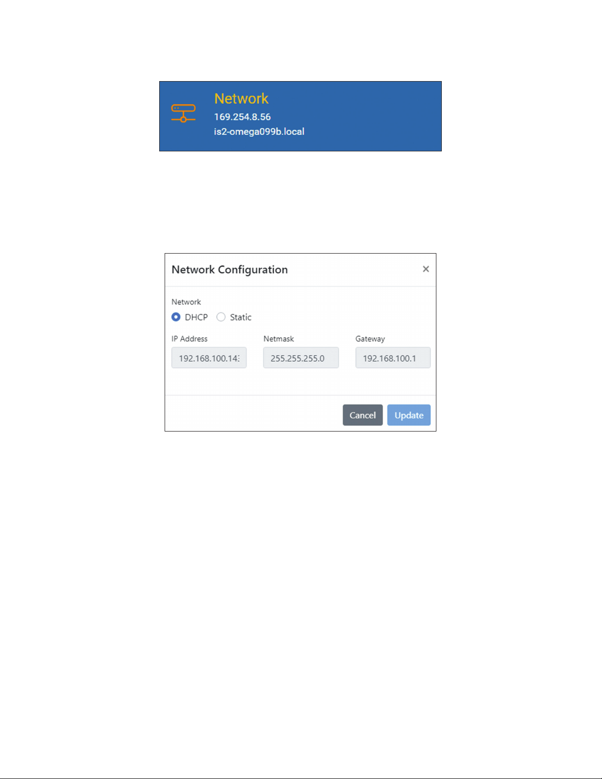
To manually change the IP Address, Netmask, and Gateway address of the iServer 2, the user must click the
primary Network Tab from the main iServer 2 web UI page.
Click the Static bubble as shown in section 6.5.1 Network Conguration to enable the manual conguration of
the IP Address, Netmask, and Gateway addresses.
6.5.1. Network Configuration
Clicking the Network tab of the iServer 2 web UI provides a window to congure IP parameters and
Ethernet interface options.
Figure 39: iServer 2 web UI Network tab
Figure 40: DHCP/Static network configuration window
• DHCP – If the DHCP bubble is selected, the iServer 2 will dynamically request an IP address, a subnet
mask, a gateway address, and a DNS address from the DHCP server. The DHCP option is enabled by
default.
• Static – If the Static bubble is selected, the user will be able to congure the IP Address, Netmask,
and Gateway address for the iServer 2 manually.
• IP Address – This indicates the IP address of the iServer. When DHCP is enabled, this eld will be
dimmed. When Static is enabled, the IP Address can be changed.
• Netmask – A 32-bit number that is used to distinguish the network and host portions of the IP address.
The iServer 2 default Netmask is 255.255.255.0. When DHCP is enabled, this eld will be dimmed.
When Static is enabled, the IP Address can be changed.
• Gateway Address - The IP address of the router which functions as gateway to the network. This
points to the router that forwards trafc to a destination address outside of the subnet on which the
iServer 2 resides.
27Navigating the iServer 2 Web UI
Page 28
6.6. Logging
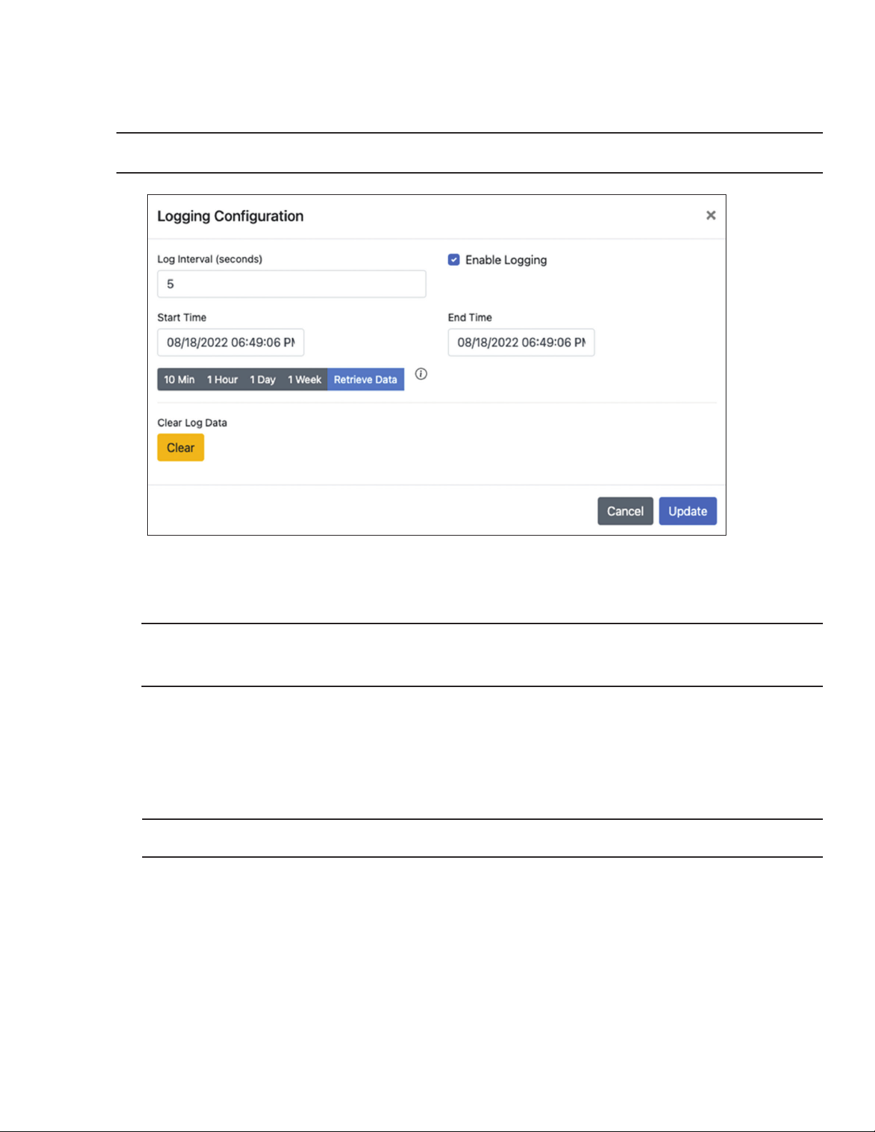
The features in the logging tab allow users to set the automatic logging interval, retrieve recorded data from
a date range, and save it as a .CSV le. The Clear Log Data button can be used to erase data that has been
recorded in the internal 11 GB memory.
Note: The maximum log interval for a Smart Probe is 66 536 seconds, or about 18 hours.
Figure 41: Logging configuration window
6.6.1. Clear Log Data When Switching Smart Probe Types (Smart Probe Models Only)
Important: The iServer 2 accepts a multitude of different Omega Link Smart Probe types. If the user
intends to plug in a Smart Probe of a different measurement type, the Clear Log Data button must be
pressed before the new Smart Probe is plugged in.
Follow the instructions below to complete the process:
Step 1: Unplug the Smart Probe currently plugged in to the iServer 2 unit.
Step 2: Click the Clear Log Data button on the iServer 2 web UI. The iServer 2 will reboot.
Step 3: Plug in the new Smart Probe.
Note: This function is only available when logged in as an Admin to the webserver.
28 iServer 2 User's Manual
Page 29
6.6.2. How to Retrieve Logged Data
After a date range is set, click Retrieve Data to download the logged data as a .CSV le. If changes are
made to the logging interval, click Update to nalize the changes.
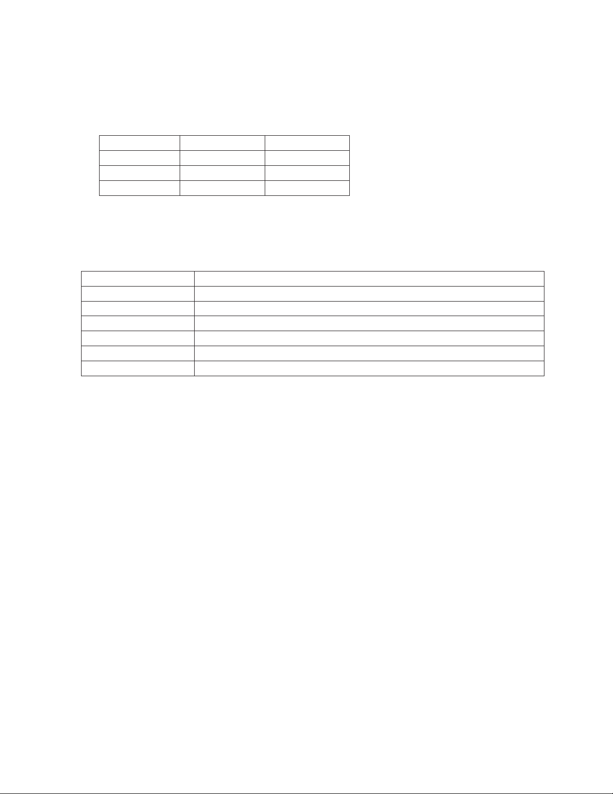
The log interval can be congured to change the frequency that data is logged. Data will be logged into
the internal 11 GB memory. Some Smart Probes come with more than one active sensor. These sensors
can be individually enabled or disabled using Omega’s SYNC conguration software. The log interval can
be congured to adjust the lifespan of the internal memory capacity according to this table:
Sample Rate 2 Active Sensors 4 Active Sensors
1 second (max) 4 years 2 years
5 seconds 24 years 12 years
10 seconds 40 years 20 years
6.7. Events and Notifications Configuration
The Events and Notications window of the iServer 2 web UI allows users to congure alarm thresholds,
triggers, and notication parameters. The following table describes the available alarm triggers.
Alarm Trigger Description
System Error Noties the user when there is a probe fault.
Battery Level Warning Noties the user when the iServer 2 battery power is running low.
TTL Contact Activation Noties the user when a Contact Closure alarm has been triggered.
Probe Disconnection Noties the user when a probe has been disconnected from the iServer 2.
Out of Memory Noties the user when the internal iServer 2 memory is full.
Power Reset Noties the user when a power reset has occurred.
29Navigating the iServer 2 Web UI
Page 30
6.7.1. Buzzer
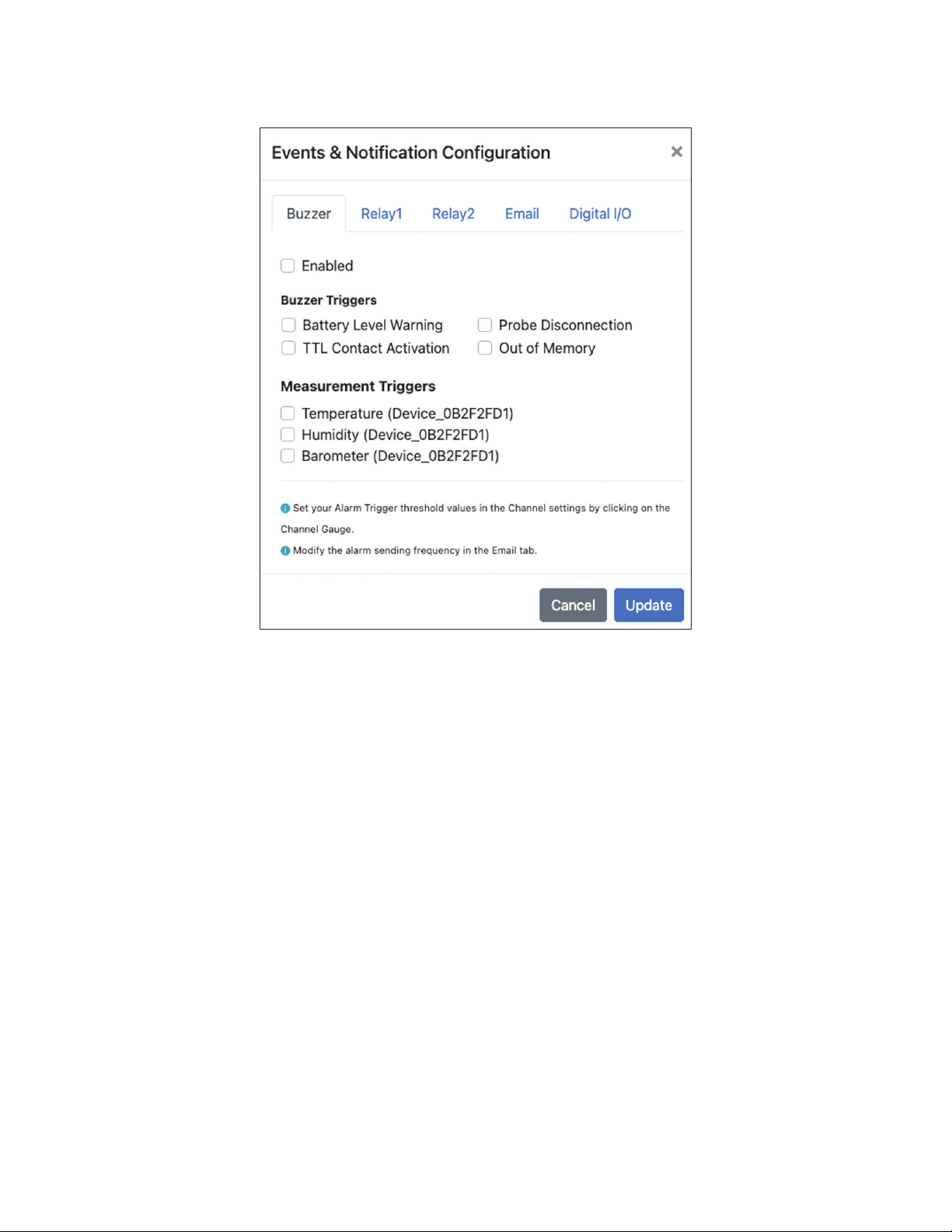
From the Alarm tab, users can enable or disable the alarm notication, set the trigger event, and select
the measurement device that the alarms will apply to.
Figure 42: iServer 2 buzzer alarm notification configuration
30 iServer 2 User's Manual
Page 31
6.7.2 . Relay 1 and Relay 2
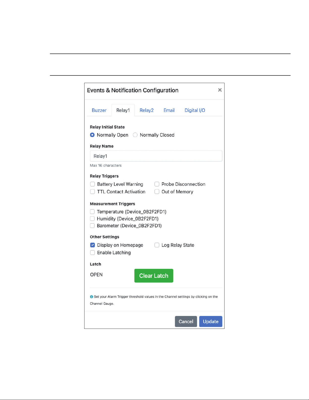
The Relay 1 and Relay 2 tabs allow users to congure the rst and second relays of the iServer 2. The
initial relay states can be changed between Normally Open and Normally Closed. The relay triggers and
input devices they apply to can be selected in this window as well. For more information regarding the
relay connector, refer to section 4.3 Digital I/O and Relays.
Important: When wiring the included terminal block connectors to access the digital I/O, alarms, or
relays, it is recommended that users ground the unit by connecting a wire to the chassis ground of the
connectors shown in Figure 9.
Figure 43: Relay notification configuration window
31Navigating the iServer 2 Web UI
Page 32
6.7.3. Email
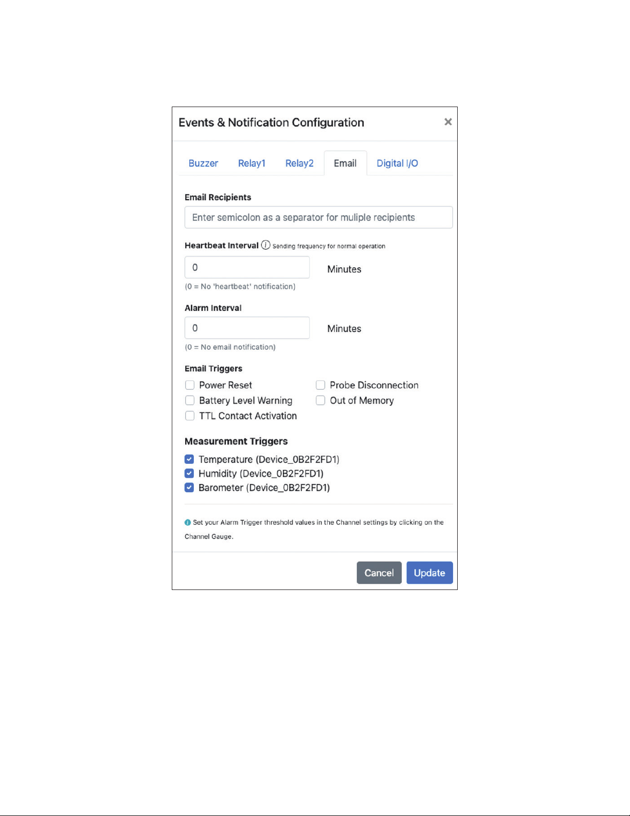
From the Email tab, users can create a list of recipients who will be notied via email depending on
the parameters that are established. The Heartbeat Interval provides normal operation updates at a
congurable frequency. The Alarm Interval controls the frequency of alarm notications that will be sent
via email after the initial notication is sent.
Figure 44: iServer 2 email notification configuration
32 iServer 2 User's Manual
Page 33
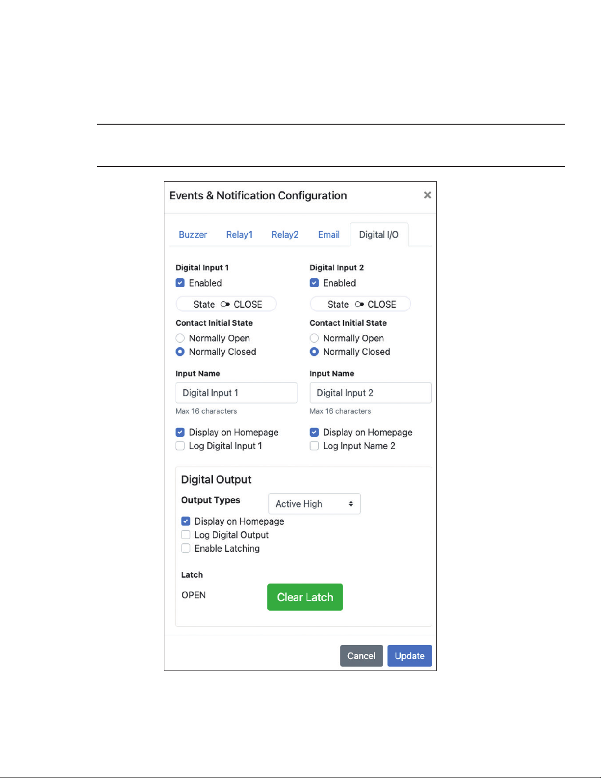
6.7.4. Digital I/O
The Digital I/O tab is used to congure the rst and second Digital Inputs on the iServer 2. Both can be
enabled or disabled independently of one another and can be set to be displayed on the homepage or
Log. For wiring and pinouts, refer to section 4.3 Digital I/O and Relays. The initial state of the contacts can
be set to Normally Open or Normally Closed.
The Digital Output can be set to Active High or Active Low.
Important: When wiring the included terminal block connectors to access the digital I/O, alarms, or
relays, it is recommended that users ground the unit by connecting a wire to the chassis ground of the
connectors shown in Figure 9.
Figure 45: iServer 2 Digital I/O notification configuration
33Navigating the iServer 2 Web UI
Page 34
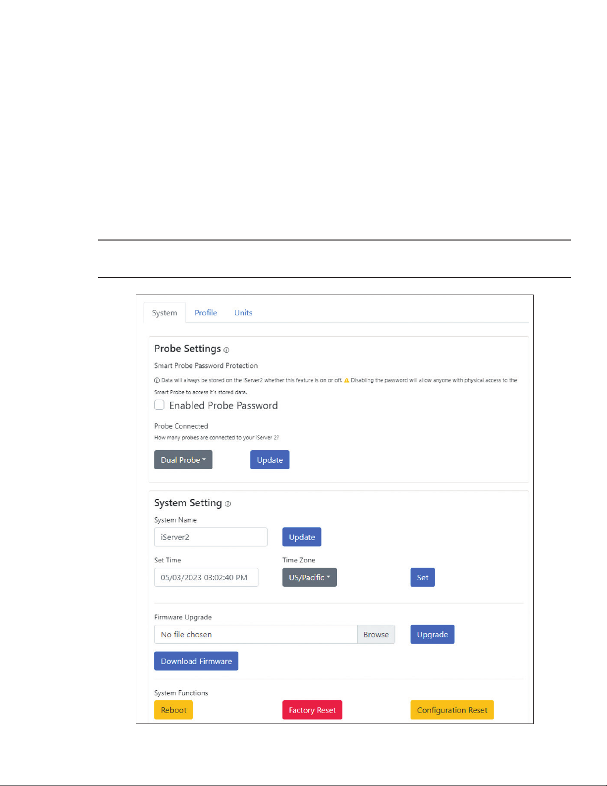
6.8. System Configuration
The System Conguration menu provides users with conguration options that affect the iServer 2 unit and
web UI. Changes to the units, date, and time will affect logging information and will be reected in the web UI
and on the iServer 2 display.
6.8.1. System - Single or Dual Probe / Thermocouple Configuration
The primary System tab allows users to control a variety of functions such as factory resets, rmware
updates, and conguring the system time.
The Probe Settings are only available on Smart Probe compatible iServer 2 models and can be set to
Single or Dual Probe and allows users to create a password for Smart Probe conguration.
The Onboard Thermocouple Selection is only available on the iS2-THB-DTC and can be set to Single or
Dual TC.
The Date, Time, and Time Zone as it appears in the UI can be set manually. Additionally, rmware update
les can be selected and uploaded here. System Reboot, Factory Reset, and Conguration Reset may be
performed here.
Caution: Clicking the Factory Reset or Conguration Reset button while a Smart Probe is plugged in to
the iServer 2 will clear any user set probe conguration settings.
Figure 46: iServer 2 system configuration window
34 iServer 2 User's Manual
Page 35
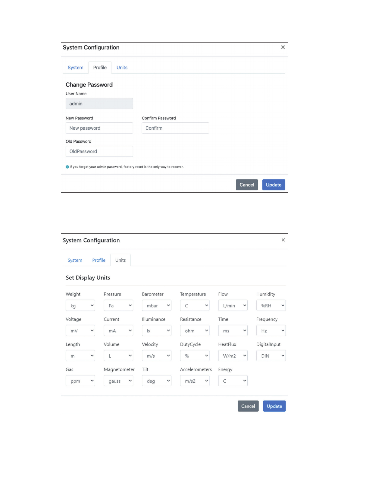
6.8.2. Profile
The Prole tab allows users to update their username and password.
6.8.3. Units
The Units tab allows users to congure the displayed units of measure as they appear in the web UI.
Figure 47: iServer 2 web UI User Name and Password configuration
Figure 48: iServer 2 web UI display units configuration
35Navigating the iServer 2 Web UI
Page 36
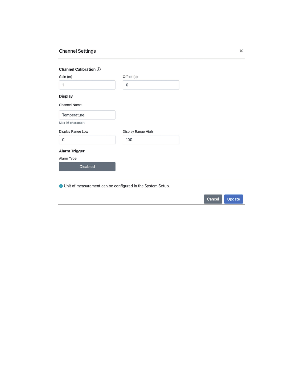
6.9. Channel Settings
Clicking on the individual gauge display readings in the web UI will bring up the Channel Settings window.
Gain and Offset values can be applied, display ranges can be set, and alarm triggers can be dened. If any
congurations are made to this menu, the user must click Update to nalize the changes.
6.9.1 . Gain and Offset
A Gain value is a multiplier added to the sensor reading value. The Gain value can be positive, negative,
and/or a decimal value. A decimal value will divide the sensor reading. A negative value will invert the
sensor reading. An Offset value adds or subtracts a constant value to the sensor reading. The offset is
applied after the Gain.
The equation for an input value scaled by Gain and Offset is given below:
6.9.2. Alarm Trigger
Alarms for a channel input may be congured to trigger based thresholds that can be set to a range
(High Low), Above, or Below a certain reading.
Figure 49: Sensor input channel configuration
Input
Scaled
= (Input
X Gain) + Offset
Raw
36 iServer 2 User's Manual
Page 37
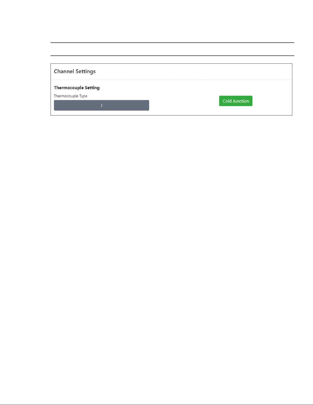
6.9.3. Thermocouple Configuration Interface (TC Models Only)
Thermocouple compatible models of the iServer 2 offer a Cold Junction Calibration feature in the web UI.
To begin cold junction calibration, follow the steps below:
Note: Cold Junction Calibration is not available for thermocouple types: R, S, and B.
Figure 50: Thermocouple Cold Junction Calibration
Step 1: Click on the channel readings for the input that will undergo cold junction calibration.
Step 2: Click on the Cold Junction button.
Step 3: Click the Proceed button.
Step 4: Once notied by the web UI that the calibration was successful, click OK to nalize the changes.
37Navigating the iServer 2 Web UI
Page 38
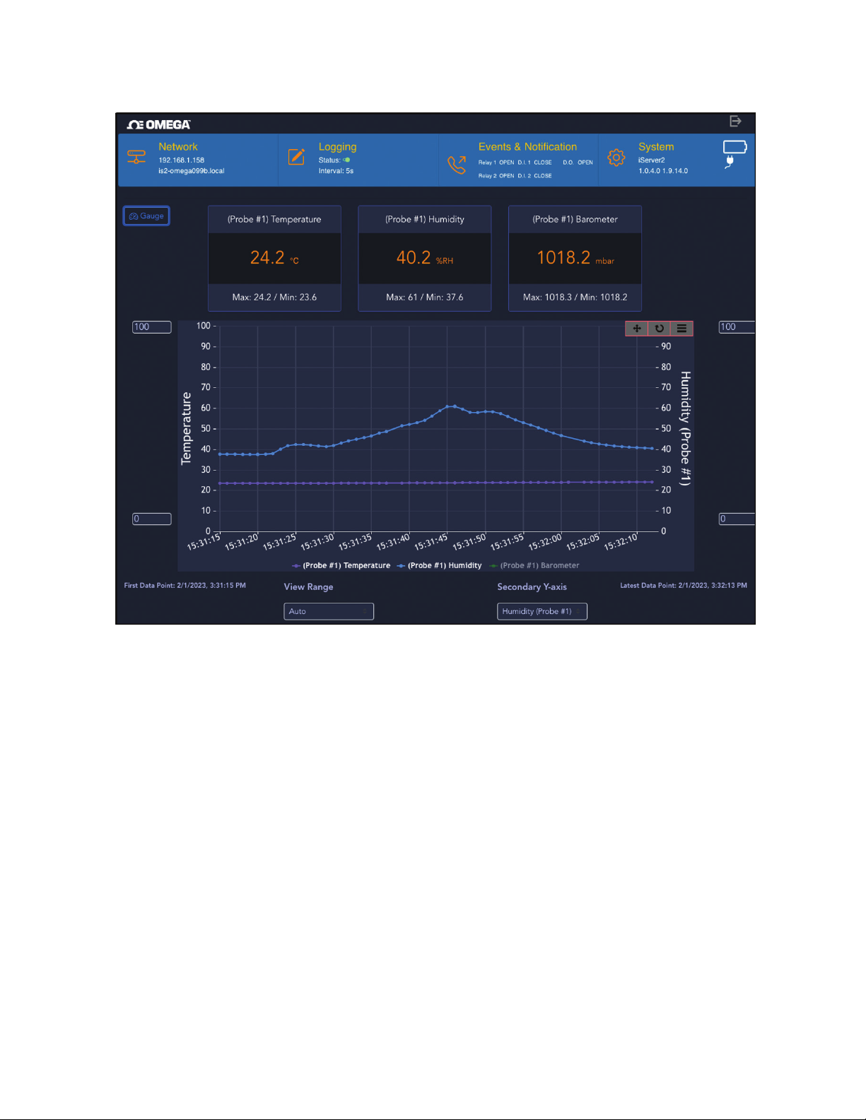
6.10. Gauge/Chart Web UI View
The iServer 2 web UI presents sensor readings in Gauge View by default, however, users can select the Chart
button to enable Chart View.
Figure 51: iServer 2 web UI - Chart View
From Chart View, users can still access the different sensor channel inputs by clicking the readings. Live
readings will be graphed automatically once the Chart View is enabled. View range and the Secondary Y-Axis
source can be updated by clicking the buttons at the bottom of the UI, while the Maximum and Minimum
graphed values can be adjusted on the left and right sides of the chart.
38 iServer 2 User's Manual
Page 39
7. Adding an iServer 2 to Omega Enterprise Gateway (OEG)
iServer 2 devices can be added to Omega Enterprise Gateway 2.4 (OEG) in a non-internet environment by
adding the iServer 2 to OEG as a device. An active OEG license and access to a Windows 7, 8, 9, or 10 OS PC is
required to download and run OEG. OEG can be purchased and downloaded from the following link:
https://www.omega.com/en-us/oeg
There are two methods to connect the iServer 2 to OEG. The rst method requires the iServer 2 to be set to the
default DHCP network setting and requires access to a DHCP-enabled router with an open port and an RJ45
Ethernet cable. The second method requires Administrator access to the Windows OS PC running OEG and
requires the iServer 2 to be set to the Static IP network setting and the iServer 2 unit to be plugged in directly to
the Windows PC.
7.1. Method 1 - DHCP Router Method
To add an iServer 2 to OEG using the DHCP router method, begin by ensuring the iServer 2 is set to the
default DHCP network settings (6.5.1 Network Conguration) and follow the steps below.
Step 1: Connect the iServer 2 unit to a DHCP-enabled router using an RJ45 Ethernet cable.
Step 2: Ensure the Windows PC that will run OEG is on the same network as the connected iServer 2.
Step 3: Launch and log in to your OEG account.
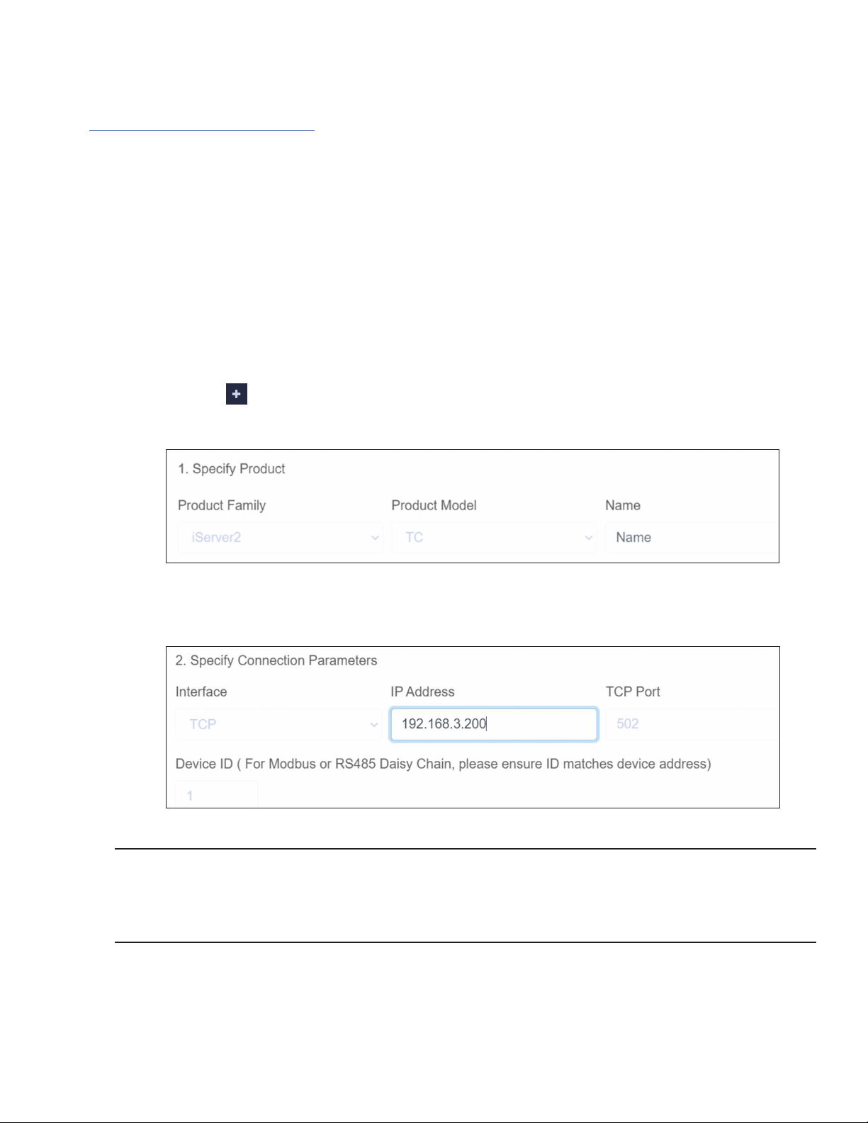
Step 4: Click the icon or Add Devices. Then select iServer 2 from the Product Family dropdown and
click TC or Probe from the Product Model dropdown, depending on the model of iServer 2 being
connected.
Figure 52: OEG Add Devices menu - iServer 2 Model
Step 5: Input the IP Address of the connected iServer 2 as it appears in your local-area network.
Figure 53: OEG Add Devices menu - Connection Parameters
Important: If the DHCP-enabled iServer 2 unit has been disconnected and moved to a separate DHCPenabled, local-area network router or PC, the user must identify the new IP Address that the unit has been
assigned under the local-area network. For models with a display, the new IP Address will appear on the unit
display. For models without a display, users can access the iServer 2 web UI to check the new IP Address
(6.5.1 Network Conguration).
Step 6: Click Add to nalize the conguration.
All sensing devices connected to the iServer 2 will appear on OEG after the pairing is successful. The
readings from ofine units will display NaN. For more information on how to navigate OEG, refer to the OEG
Software User’s Manual.
39Adding an iServer 2 to Omega Enterprise Gateway (OEG)
Page 40
7.2. Method 2 - Static IP Method (Direct to PC)
To add an iServer 2 to OEG using the Static IP (direct to PC) method, begin by ensuring the iServer 2 is set to
the Static IP network settings (6.5.1 Network Conguration) and conrm the Static IP address is set to the
preferred address. The Windows PC network settings will need to be congured to properly pair the iServer 2
and OEG. Follow the steps below:
Important: Administrator access to the Windows PC is required to congure the Network settings of the PC.
Step 1: Navigate to the iServer 2 web UI and assign a Static IP address to the iServer 2 unit. Then exit the
web UI.
Step 2: Connect the iServer 2 unit directly to the Windows PC with OEG using
an RJ45 Ethernet cable.
Step 3: Navigate to the Windows Control Panel and click Network and
Sharing Center.
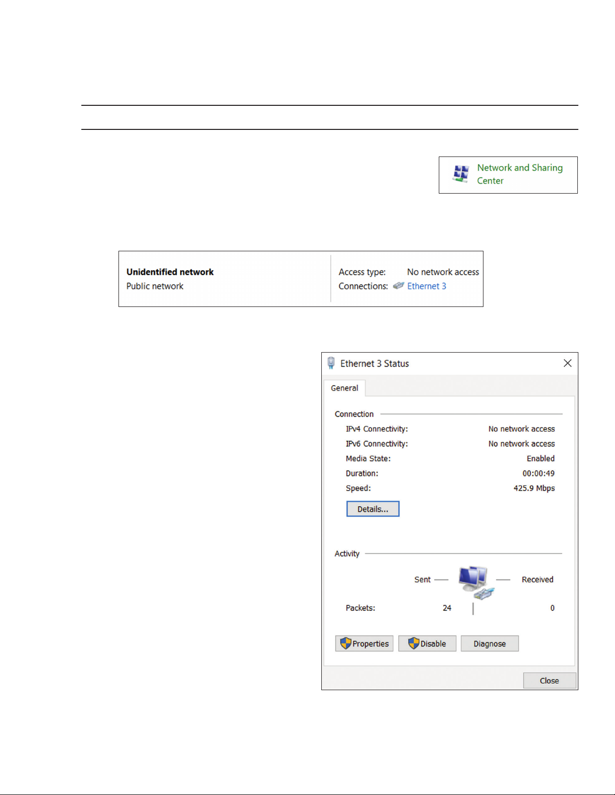
Step 4: Click the Unidentied Network Connection.
Figure 55: Network and Sharing Center - Unidentified Network
Figure 54: Windows Control Panel
Network and Sharing Center
Step 5: Click Properties.
Figure 56: Unidentified Network Status
40 iServer 2 User's Manual
Page 41
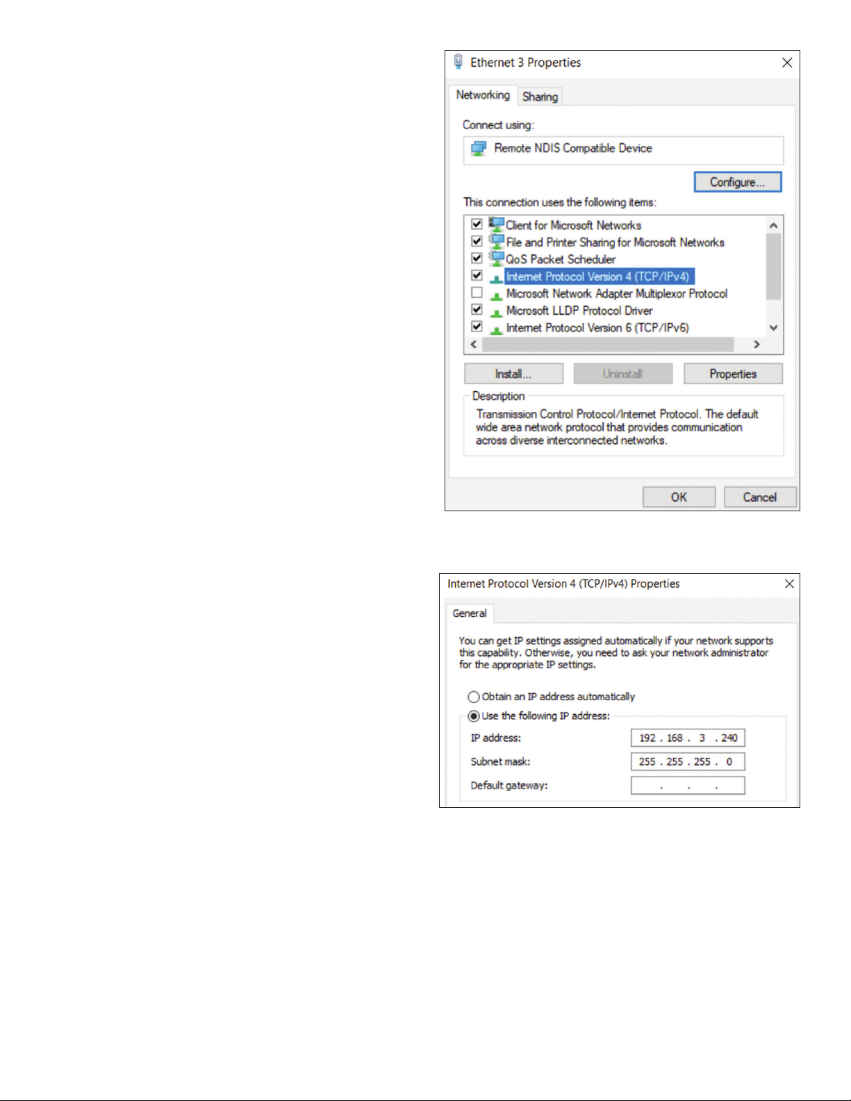
Step 6: Click Internet Protocol Version 4 (TCP/IPv4)
to highlight the selection and then click
Properties.
Step 7: Click Use the following IP address and
enter an IP address that uses the same
network part (the rst nine digits of the IP
address) but with a unique host part (the
last three digits of the IP address) as the
static IP Address assigned to the iServer 2
in Step 1.
For example, if the Static IP assigned to
the iServer 2 is: 192.168.3.200, then the IP
address entered in the text box should be:
192.168.3.XXX (the XXX should be any
value that is NOT 200)
Figure 57: Unidentified Network Properties
Step 8: Click OK to nalize.
Step 9: Launch OEG and log in to your account.
Figure 58: TCP/IPv4 and subnet mask properties for micro USB
2.0 connection
41Adding an iServer 2 to Omega Enterprise Gateway (OEG)
Page 42
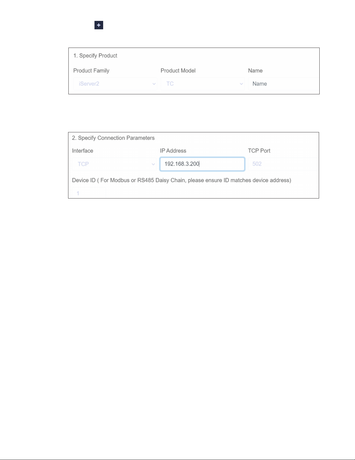
Step 10: Click the icon or Add Devices. Then select iServer 2 from the Product Family dropdown and
click TC or Probe from the Product Model dropdown, depending on the model of iServer 2 being
connected.
Figure 59: OEG Add Devices menu - iServer 2 Model
Step 11: Input the static IP Address of the connected iServer 2.
Figure 60: OEG Add Devices menu - Connection Parameters
Step 12: Click Add to nalize your conguration.
All sensing devices connected to the iServer 2 will appear on OEG after the pairing is successful. The
readings from ofine units will display NaN. For more information on how to navigate OEG, refer to the OEG
Software User’s Manual.
7.3. Configuring Sensing Devices after Pairing with OEG
If a sensing device paired to the iServer 2 has been congured or modied after the iServer 2 has been
added to OEG, the user must reboot the iServer 2 and restart the OEG software to sync with the conguration
made to the connected device.
42 iServer 2 User's Manual
Page 43

8. iServer 2 Modbus Holding Register Partition
The following section details the Modbus Register list associated with the iServer 2.
8.1. Holding Registers Partition
The iServer 2 Modbus registers are partitioned as listed below in the table below.
Address Description Usage
0x0000 – 0x0063 Channel readings (read only) Readings from the iserver2
0x0064 – 0x0191 Device meta Model number, rmware version, device information
0x0192 – 0xFFFF Conguration Conguration registers for device and readings
8.2. Channel Value Registers
Channel registers range from 0000 to 0063. All registers in this range are read-only. Each measurement or
input consists of 2 registers. The registers are dened as:
Register 1 Register 2
Value (IEEE 754 oating point value)
NaN is used as an indicator for no measurements, disabled, hardware failure, out of spec, etc..
The iServer2 queries different probes depending on the model. “Probe 0” is for thermocouple readings only
available for -DTC models. “Probe 1” and “Probe 2” are designated for Omega Link Smart Probes attached
to Smart Probe compatible variants of the iServer 2. Each “Probe” has a maximum of 4 channels (0-3). The
Modbus address can be calculated as such:
Modbus address = (probe number)*8 + (channel_number)*2
Floating point value of the measurement if the value is NaN:
• 0x7f800000: value error
• 0x7f800001: open
• 0x7f800002: short
• 0x7f800003: range
Register
(Decimal)
0 0x0000
2 0x0002
8 0x0008 Probe 1 Channel 0 reading R Float Smart probe 1 channel 0 2
10 0x000A Probe 1 Channel 1 reading R Float Smart probe 1 channel 1 2
12 0x000C Probe 1 Channel 2 reading R Float Smart probe 1 channel 2 2
14 0x000E Probe 1 Channel 3 reading R Float Smart probe 1 channel 3 2
16 0x0010 Probe 2 Channel 0 reading R Float Smart probe 2 channel 0 2
18 0x0012 Probe 2 Channel 1 reading R Float Smart probe 2 channel 1 2
20 0x0014 Probe 2 Channel 2 reading R Float Smart probe 2 channel 2 2
22 0x0016 Probe 2 Channel 3 reading R Float Smart probe 2 channel 3 2
Register
(Hex)
Description RW Type Values
Thermocouple 1 Channel 0
reading
Thermocouple 2 Channel 1
reading
R Float
R Float
Thermocouple 1 channel 0
reading
Thermocouple 2 channel 1
reading
Register
Size
2
2
43iServer 2 Modbus Holding Register Partition
Page 44

8.3. Device Meta Modbus Registers
Channel registers range from 0x0064 to 0x0191. Device meta registers dene device meta information
including rmware, name, etc.
Register
(Decimal)
100 0x0064 Model R STRING_16 Max 16 Character Model 8
114 0x0072 Firmware Version R UINT_32
116 0x0074 Hardware Version R UINT_32
118 0x0076 Device ID R UINT_32
120 0x0078 Device Name R/W STRING_16
134 0x0086 Manufactured Date R UINT_32 Date comes from probe 0 2
136 0x0088 Calibrated Date R UINT_32 Date comes from probe 0 2
Register
(Hex)
Description RW Type Values
8.4. Device Configuration and Channel Configuration Registers
Device conguration and channel conguration range from 0x0192 – 0xFFFF.
Register
(Decimal)
402 0x0192 Log Enable R/W UINT_16 0 – disable, 1- enable 1
403 0x0193 Log Rate R/W UINT_16 Logging rate in seconds 1
404 0x0194 Buzzer Triggers R/W UINT_32
406 0x0196 Relay 1 Triggers R/W UINT_32
408 0x0198
410 0x019A Relay 1 Clear Latch W UINT_32 1-Clear latch 2
412 0x019C Relay 1 Name R/W STRING_16 Max 16 chars 8
420 0x01A4 Relay 2 Triggers R/W UINT_32
422 0x01A6
424 0x01A8 Relay 2 Clear Latch W UINT_32 1-Clear latch 2
426 0x01AA Relay 2 Name R/W STRING_16 Max 16 chars 8
Register
(Hex)
Description RW Type Values
Relay 1
Conguration
Relay 2
Conguration
R/W UINT_32
R/W UINT_32
32-bit integer. Translate to
form of major, minor, bug,
build, corresponding to each
byte
32-bit integer. Value
interpolates as REV xxx
Unique identier such as serial
number. 32-bit integer
Device name, Max 16
characters
Event triggers for turning
on the buzzer.
Event triggers for opening/
closing relay1.
Bit 0–0-normally closed,
1-normally open
Bit 1– 0-don’t log, 1-log
Bit 2–0-don’t display on
homepage, 1-display on
homepage
Bit 3–0–disable latching,
1-enable latching
Event triggers for opening/
closing relay2.
Bit 0 – 0- normally closed,
1-normally open
Bit 1 – 0- don’t log, 1- log
Bit 2 – 0 -don’t display on
homepage, 1- display on
homepage
Bit 3 – 0 – disable latching,
1- enable latching
Register
Size
2
2
2
8
Register
Size
2
2
2
2
2
44 iServer 2 User's Manual
Page 45

Register
(Decimal)
434 0x01B2
435 0x01B3
436 0x01B4
437 0x01B5
438 0x01B6
441 0x01B9
442 0x01BA
443 0x01BB
444 0x01BC
445 0x01BD
446 0x01BE
447 0x01BF
448 0x01C0
464 0x01D0
472 0x01D8
496 0x01F0
504 0x01F8
Register
(Hex)
Description RW Type Values
Probe 0 Sensor
Count
Probe 1 Sensor
Count
Probe 2 Sensor
Count
Thermocouple
1 Channel 0
measurement
type
Thermocouple
2 Channel 1
measurement
type
Probe 1 Channel
0 measurement
type
Probe 1 Channel
1 measurement
type
Probe 1 Channel
2 measurement
type
Probe 1 Channel
3 measurement
type
Probe 2 Channel
0 measurement
type
Probe 2 Channel
1 measurement
type
Probe 2 Channel
2 measurement
type
Probe 2 Channel
3 measurement
type
Thermocouple 1
Channel 0 name
Thermocouple 2
Channel 1 name
Probe 1 Channel
0 name
Probe 1 Channel
1 name
R UINT_16 Number of active thermocouples 1
R UINT_16 Sensor count on smart probe 1 1
R UINT_16 Sensor count on smart probe 2 1
R UINT_16
R UINT_16
R UINT_16
R UINT_16
R UINT_16
R UINT_16
R UINT_16
R UINT_16
R UINT_16
R UINT_16
R/W STRING_16
R/W STRING_16
R/W STRING_16 Smart probe 1 channel 0 name 8
R/W STRING_16 Smart probe 1 channel 1 name 8
Thermocouple 1 channel 0
measurement type
Thermocouple 2 channel 1
measurement type
Smart probe 1 channel 0
measurement type
Smart probe 1 channel 1
measurement type
Smart probe 1 channel 2
measurement type
Smart probe 1 channel 3
measurement type
Smart probe 2 channel 0
measurement type
Smart probe 2 channel 1
measurement type
Smart probe 2 channel 2
measurement type
Smart probe 2 channel 3s
measurement type
Thermocouple 1 channel 0
name
Thermocouple 2 channel 1
name
Register
Size
1
1
1
1
1
1
1
1
1
1
8
8
45iServer 2 Modbus Holding Register Partition
Page 46

Register
(Decimal)
512 0x0200
520 0x0208
528 0x0210
536 0x0218
544 0x0220
552 0x0228
560 0x0230
562 0x0232
568 0x0238
570 0x023A
572 0x023C
574 0x023E
576 0x0240
578 0x0242
580 0x0244
582 0x0246
584 0x0248 Probe 0 Name R/W STRING_16 Onboard msp name 8
592 0x0250 Probe 1 Name R/W STRING_16 Smart probe 1 name 8
600 0x0258 Probe 2 Name R/W STRING_16 Smart probe 2 name 8
Register
(Hex)
Description RW Ty pe Values
Probe 1 Channel
2 name
Probe 1 Channel
3 name
Probe 2 Channel
0 name
Probe 2 Channel
1 name
Probe 2 Channel
2 name
Probe 2 Channel
3 name
Thermocouple 0
unit
Thermocouple 1
unit
Probe 1 Channel
0 unit
Probe 1 Channel
1 unit
Probe 1 Channel
2 unit
Probe 1 Channel
3 unit
Probe 2 Channel
0 unit
Probe 2 Channel
1 unit
Probe 2 Channel
2 unit
Probe 2 Channel
3 unit
R/W STRING_16
R/W STRING_16
R/W STRING_16
R/W STRING_16
R/W STRING_16
R/W STRING_16
R STRING_4 Thermocouple 1 unit 2
R STRING_4 Thermocouple 2 unit 2
R STRING_4
R STRING_4
R STRING_4
R STRING_4
R STRING_4
R STRING_4
R STRING_4
R STRING_4
Smart probe 1
channel 2 name
Smart probe 1
channel 3 name
Smart probe 2
channel 0 name
Smart probe 2
channel 1 name
Smart probe 2
channel 2 name
Smart probe 2
channel 3 name
Smart probe 1
channel 0 unit
Smart probe 1
channel 1 unit
Smart probe 1
channel 2 unit
Smart probe 1
channel 3 unit
Smart probe 2
channel 0 unit
Smart probe 2
channel 1 unit
Smart probe 2
channel 2 unit
Smart probe 2
channel 3 unit
Register
Size
8
8
8
8
8
8
2
2
2
2
2
2
2
2
46 iServer 2 User's Manual
Page 47

9. Appendix: Troubleshooting
See the table below for error messages and descriptions that may appear while operating the iServer 2.
Error Message Description
OPEN Probe sensor reads open, or thermocouple disconnected
SHORT Sensor is shorted
RANGE Reading is out of range
NAN / INVAL Reading is invalid
47Appendix: Troubleshooting
Page 48
10. iServer 2 Specifications
INTERFACES
Available input ports vary depending on the iServer 2 model
Ethernet (RJ45): 1x port (Power over Ethernet available on qualifying models)
Supported Protocols: TCP, UDP, SNMP, SNTP, ARP, ICMP, DNS, HTTP, and Telnet
Omega Link Smart Probe: 1x M12 8-Pin port (PN#: M12-MT-079-2F cable is required for dual Smart Probe
functionality, sold separately)
Thermocouple: 2x ports (available on qualifying models)
Digital I/O and Relays: 2x RS232/RS485 1.5 A @ 30 V DC
LED Indicators: 100 BASE-T, Network Link and Activity, DHCP, Internet
Alarm I/O: Two contact inputs TTL 0.5; one open collector output 150 mA @ 30 V DC
Sample Rate: 8 samples/second max
Memory Capacity and Sample Rate: The table below lists the lifespan of the internal storage before the 11 GB
of storage is lled. Some Smart Probes come with more than one active sensor. These sensors can be
individually enabled and disabled using Omega’s SYNC conguration software.
Sample Rate 2 Active Sensors 4 Active Sensors
1 second (max) 4 years 2 years
5 seconds 24 years 12 years
10 seconds 40 years 20 years
Management: Device and probe conguration and monitoring through embedded WEB server
Embedded WEB Server: Servers WEB pages containing real-time data and live updated gauge views and charts
within denable time intervals.
MECHANICAL
Dimensions of Base Device: 101.6 mm L x 155.6 mm W x 330 mm H (4 in. L x 6.13 in. W x 12.99 in. H) not
including bracket and M12 connector
Material: Stainless Steel
Display: LCD 32 mm L x 93.5 mm W
Weight: 655 g (1.44 lbs.), including battery
POWER
Power Input: 9 to 12 V DC
Consumption: 4 W
AC Power Adapter (Included) Nominal Output: 12 V DC @ 1.5 A
Power Over Ethernet: IEEE 802.3AF, 44 V – 49 V, Power Consumption under 10 W
Input: 100 to 240 V AC, 50/60 Hz
Back-Up Battery: 9 V DC, alkaline. 96 hours at 5 seconds recording intervals and 1 second reading with two
connected probes
ENVIRONMENTAL
Operating Temperatures
iServer 2 Unit: 0 to 60°C (32 to 140°F)
Battery: -18 to 55°C (-0.4 to 131°F)
AC Power Adapter: 0 to 40°C (32 to 104°F)
Industrial Cable: -40 to 125°C (-40 to 257°F)
Storage Temperature: -40 to 85°C (-40 to 185°F)
GENERAL
Conguration: Internal Web UI
Software: Access web server using any modern web browser such as Chrome, Edge, or Firefox on the same
local network; Firmware upgrade from Internet; Export probe data log to CSV les
Agency Approvals: CE, UKCA, Canada ICES-3(B)/NMB-3(B), FCC (Part 15, Subpart B, Class B of the FCC rules)
This device complies with part 15 of the FCC Rules. Operation is subject to the following two conditions: (1) This
device may not cause harmful interference, and (2) this device must accept any interference received, including
interference that may cause undesired operation.
Changes or modications made to this equipment not expressly approved by Omega Engineering, Inc. may void
the user’s authorization to operate this equipment.
48 iServer 2 User's Manual
Page 49

WARRANTY/DISCLAIMER
OMEGA ENGINEERING, INC. warrants this unit to be free of defects in materials and workmanship for a period
of 13 months from date of purchase. OMEGA’s WARRANTY adds an additional one (1) month grace period to
the normal one (1) year product warranty to cover handling and shipping time. This ensures that OMEGA’s
customers receive maximum coverage on each product.
If the unit malfunctions, it must be returned to the factory for evaluation. OMEGA’s Customer Service
Department will issue an Authorized Return (AR) number immediately upon phone or written request.
Upon examination by OMEGA, if the unit is found to be defective, it will be repaired or replaced at no charge.
OMEGA’s WARRANTY does not apply to defects resulting from any action of the purchaser, including but
not limited to mishandling, improper interfacing, operation outside of design limits, improper repair, or
unauthorized modification. This WARRANTY is VOID if the unit shows evidence of having been tampered
with or shows evidence of having been damaged as a result of excessive corrosion; or current, heat,
moisture or vibration; improper specification; misapplication; misuse or other operating conditions outside
of OMEGA’s control. Components in which wear is not warranted, include but are not limited to contact
points, fuses, and triacs.
OMEGA is pleased to offer suggestions on the use of its various products. However, OMEGA neither assumes
responsibility for any omissions or errors nor assumes liability for any damages that result from the use of its
products in accordance with information provided by OMEGA, either verbal or written. OMEGA warrants only
that the parts manufactured by the company will be as specified and free of defects. OMEGA MAKES NO OTHER
WARRANTIES OR REPRESENTATIONS OF ANY KIND WHATSOEVER, EXPRESSED OR IMPLIED, EXCEPT THAT OF
TITLE, AND ALL IMPLIED WARRANTIES INCLUDING ANY WARRANTY OF MERCHANTABILITY AND FITNESS FOR
A PARTICULAR PURPOSE ARE HEREBY DISCLAIMED. LIMITATION OF LIABILITY: The remedies of purchaser set
forth herein are exclusive, and the total liability of OMEGA with respect to this order, whether based on contract,
warranty, negligence, indemnification, strict liability or otherwise, shall not exceed the purchase price of the
component upon which liability is based. In no event shall OMEGA be liable for consequential, incidental or
special damages.
CONDITIONS: Equipment sold by OMEGA is not intended to be used, nor shall it be used: (1) as a “Basic
Component” under 10 CFR 21 (NRC), used in or with any nuclear installation or activity; or (2) in medical
applications or used on humans. Should any Product(s) be used in or with any nuclear installation or activity,
medical application, used on humans, or misused in any way, OMEGA assumes no responsibility as set
forth in our basic WARRANTY/DISCLAIMER language, and, additionally, purchaser will indemnify OMEGA
and hold OMEGA harmless from any liability or damage whatsoever arising out of the use of the Product(s)
in such a manner.
RETURN REQUESTS/INQUIRIES
Direct all warranty and repair requests/inquiries to the OMEGA Customer Service Department. BEFORE
RETURNING ANY PRODUCT(S) TO OMEGA, PURCHASER MUST OBTAIN AN AUTHORIZED RETURN (AR)
NUMBER FROM OMEGA’S CUSTOMER SERVICE DEPARTMENT (IN ORDER TO AVOID PROCESSING
DELAYS). The assigned AR number should then be marked on the outside of the return package and on any
correspondence.
The purchaser is responsible for shipping charges, freight, insurance and proper packaging to prevent
breakage in transit.
FOR WARRANTY RETURNS, please have the
following information available BEFORE contacting
OMEGA:
1. Purchase Order number under which the product
was PURCHASED,
2. Model and serial number of the product under
warranty, and
3. Repair instructions and/or specific problems
FOR NON-WARRANTY REPAIRS,
for current repair charges. Have the following
information available BEFORE contacting OMEGA:
1. Purchase Order number to cover the COST
of the repair,
2. Model and serial number of the product, and
3. Repair instructions and/or specific problems
relative to the product.
relative to the product.
OMEGA’s policy is to make running changes, not model changes, whenever an improvement is possible. This affords our customers the latest
in technology and engineering.
OMEGA is a trademark of OMEGA ENGINEERING, INC. © Copyright OMEGA ENGINEERING, INC. All rights reserved. This document may not
be copied, photocopied, reproduced, translated, or reduced to any electronic medium or machine-readable form, in whole or in part, without
the prior written consent of OMEGA ENGINEERING, INC.
consult OMEGA
Page 50

omega.com
®
M5791/0224
Improving the world, one measurement at a time.
TM
UNIVERSAL
FLOW MONITORS
 Loading...