

Page 1
User’s Guide
Shop online at
omega.com
e-mail: [email protected]
For latest product manuals:
www.omegamanual.info
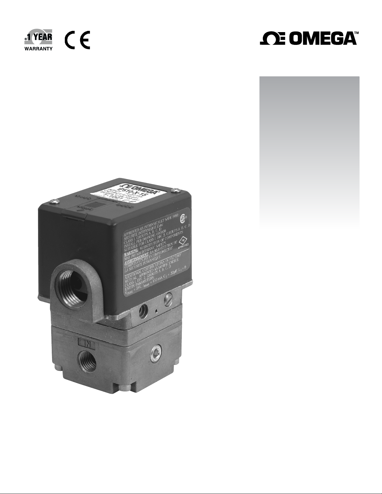
EP510, IP510, EP511, IP511 SERIES
ELECTROPNEUMATIC CONVERTERS
Page 2

omega.com [email protected]
Servicing North America:
U.S.A.
Headquarters:
For Other Locations Visit omega.com/worldwide
California Proposition 65
WARNING: Cancer and Reproductive Harm
!
www.p65Warnings.ca.gov
Omega Engineering, Inc.
Toll-Free: 1-800-826-6342 (USA & Canada only)
Customer Service: 1-800-622-2378 (USA & Canada only)
Engineering Service: 1-800-872-9436 (USA & Canada only)
Tel: (203) 359-1660 Fax: (203) 359-7700
The information contained in this document is believed to be correct, but OMEGA accepts no liability for any errors it contains, and reserves
the right to alter specifications without notice.
Page 3
M4109/0719 IP510, EP510, IP511, EP511 SERIES
A
AIR CONNECTIONS
SUPPLY
Connect air supply to 1/4 NPT port marked "IN." If the above specifications are not met, possibility of internal clogging exists. Also see
MAINTENANCE section.
OUTPUT
Connect output to 1/4 NPT port marked "OUT.”
GAUGE
The plugged 1/8 NPT port in the base of the transducer is internally connected with the "OUT" port. A pressure gauge can be attached to this
port to monitor output pressure.
CONTENTS
Air Connections . . . . . . . . . . . . . . . . . . . . . . . . . . . . . . . . . . . . . . . . . . . . . .Page 1
Pressure Requirements . . . . . . . . . . . . . . . . . . . . . . . . . . . . . . . . . . . . . . . .Page 2
Mounting . . . . . . . . . . . . . . . . . . . . . . . . . . . . . . . . . . . . . . . . . . . . . . . .Page 2
Direct Mounting
Mounting Kits
Electrical Connections . . . . . . . . . . . . . . . . . . . . . . . . . . . . . . . . . . . . . . . . .Page 3
Precautions to be observed during installation
Calibration . . . . . . . . . . . . . . . . . . . . . . . . . . . . . . . . . . . . . . . . . . . . . . . .Page 4
Maintenance . . . . . . . . . . . . . . . . . . . . . . . . . . . . . . . . . . . . . . . . . . . . . . . .Page 5
Agency Approvals, Special Notes, and Cautions . . . . . . . . . . . . . . . . . .Page 5 & 6
Kits . . . . . . . . . . . . . . . . . . . . . . . . . . . . . . . . . . . . . . . . . . . . . . . .Page 7
Specifications . . . . . . . . . . . . . . . . . . . . . . . . . . . . . . . . . . . . . . . . . . . . . . . .Page 8
WARNING
In order to get optimal service from this transducer and ensure warranty coverage the following MUST be followed:
Ÿ The supply air quality to this instrument must be instrument quality air as defined by ISA Standard 57.0.01-1996.
1. Dew point not higher than 35˚F.
2. No particulates larger than 3 microns in size.
3. Maximum oil content of 1 ppm.
Ÿ No mechanical adjustments or calibrations are necessary or allowed. All calibration MUST be done with electrical potentiometers on the
enclosed circuit board only. See “CALIBRATION” section of instructions for more information.
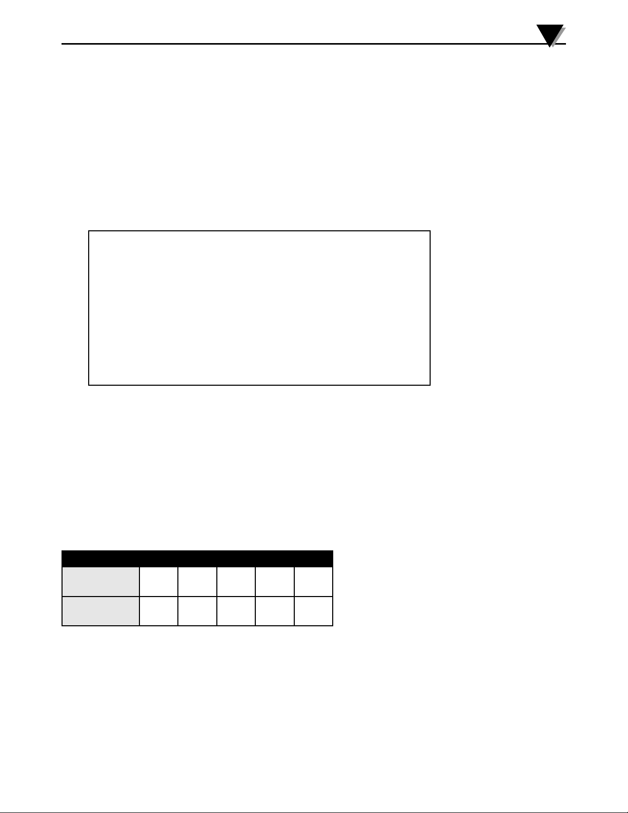
TABLE 1: SUPPLY PRESSURE REQUIREMENTS
Standard Output
Calibration
Transducer
Supply Pressure
0-60
PSI
80-120
PSI
0-120
PSI
130-140
PSI
3-15
PSI
20-100
PSI
3-27
PSI
35-100
PSI
6-30
PSI
35-100
PSI
3
Page 4
A
M4109/0719 IP510, EP510, IP511, EP511 SERIES
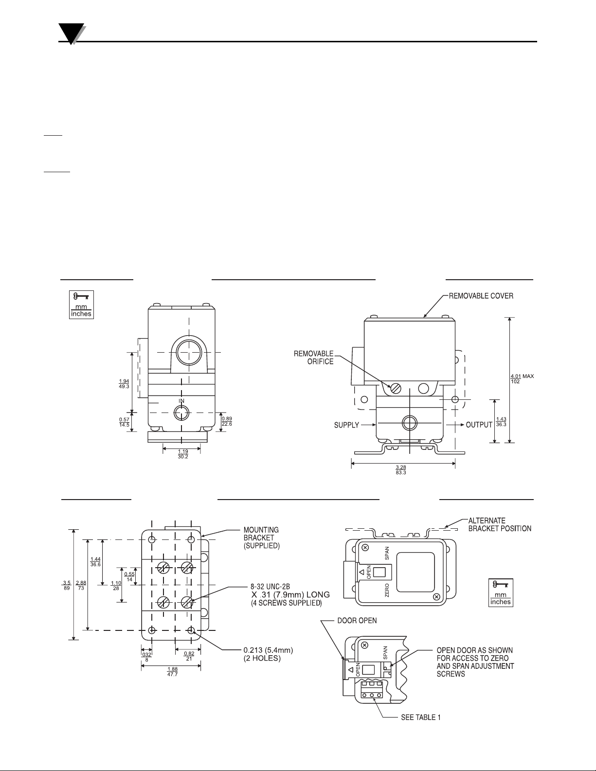
MOUNTING
GENERAL
NEMA 1 and NEMA 4X transducers can be mounted in any position.
DIRECT MOUNTING
PIPE
Ÿ Any NEMA 1 transducers may be supported by its own plumbing for air supply and output. NEMA 4X transducers may also be supported
using 1/2" explosion proof conduit in the electrical port.
PANEL
Ÿ NEMA 1 transducers may be mounted to a panel with two No. 10-32 screws using threaded holes in the back of a transducer or with two
to four No. 8-32 screws using threaded holes in the bottom of a transducer.
Ÿ NEMA 4X transducers may be mounted to a panel with three No. 10-32 screws using threaded holes in the back of a transducer or with
four No. 8-32 screws using threaded holes in the bottom of a transducer. In the case of back-mounting, if the panel extends towards the
screw-on cover, a 3/16-inch-thick spacer MUST be used between the back of the transducer and the panel in order for the panel to clear
the transducer's screw-on cover.
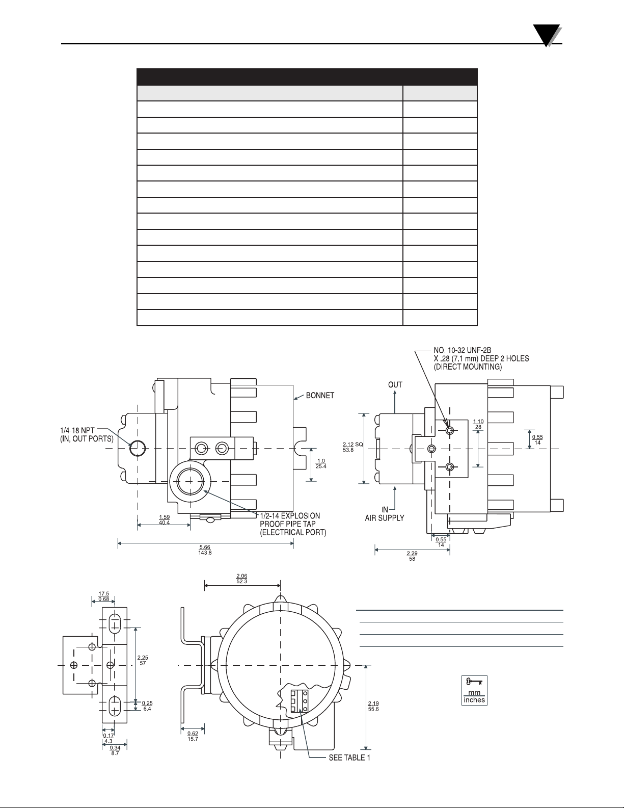
EP510 AND IP510
WEIV EDISWEIVTNORF
BOTTOM VIEW
Drawings and dimensions are for reference only.
4
WEIVPOT
Page 5
M4109/0719 IP510, EP510, IP511, EP511 SERIES
A
ELECTRICAL CONNECTIONS
PRECAUTIONS TO BE OBSERVED DURING INSTALLATION
The Transducers were tested at the EMC Test Centre, Dunfermline, Fife, KY11 5LB to the Electromagnetic Compatibility
Directive effective January 1, 1996. The relevant EMC specifications tested were the following: EN 50081-1 (1992) and EN
50082-1 (1992). A Technical Construction File, Serial #107 was written and Certificate of Conformity issued by a Competent
Body.
EN 50081-1 (1992): Test results confirmed that no precautions need to be observed during installation regarding electro-magnetic
emissions from the IP510A Transducers.
EN 50082-1 (1992): The following precautions should be taken during installation to maintain the advertised accuracy specifications for the
Transducers. The input wiring to the transducer should be isolated from other high voltage transient wiring. The momentary switching on
and off of nearby relays, motors, or other high capacitive or inductive loads can have a minor effect on the terminal based linearity
specification (1.0% of span, standard range models). Any change in output pressure is minimal and momentary, and is considered to be
within its performance capabilities. Use of a ferrite bead collar on the input wires entering the transducer is recommended should
installation next to high electromagnetic interference be necessary.
WARNING: In explosive atmospheres, electrical power must be removed from the transducer before attempting to
remove the cover and until the cover is fully reinstalled. Failure to do so may result in electrical spark or explosion.
CAUTION: Care must be used when inserting wires into the NPT port. Wires must not enter below the circuit board
due to sensitive mechanical components.
DIRECTIONS
1. Remove the cover (see WARNING above).
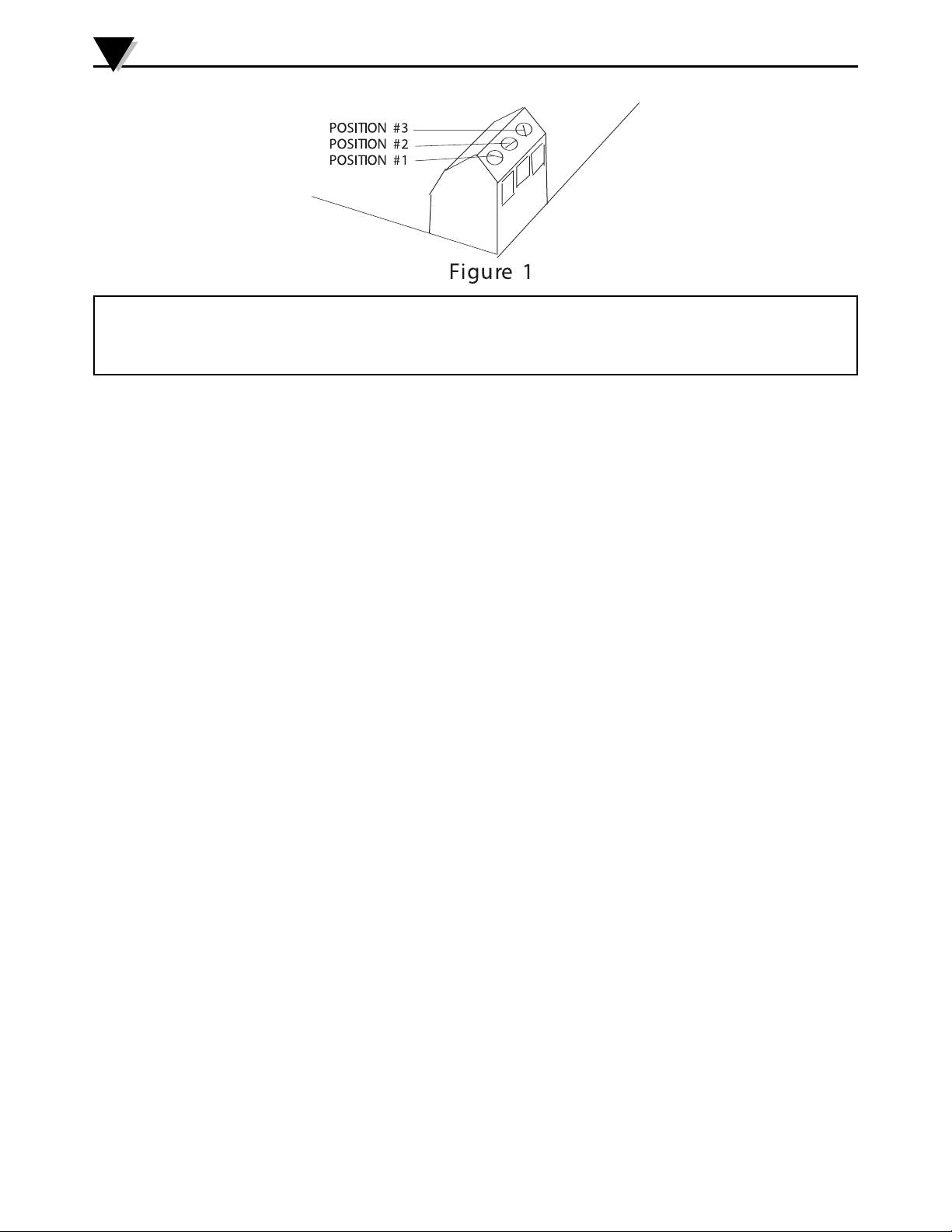
22.. Bring wiring to the terminal block, located on the circuit board, through 1/2 NPT electrical conduit connection. 18 A.W.G. is
recommended; 14 A.W.G. is the maximum wire size. Connect wires to the terminal block per TABLE 2. Care must be exercised to
prevent damage to delicate internal parts when inserting wiring through the 1/2” NPT conduit opening.
3. An internal grounding screw is provided on all units to facilitate separate ground when required. An external grounding lug is also
provided on NEMA 4X enclosures.
4. Reinstall the cover tightly using all o-rings and locking devices to insure compliance with Agency Approvals.
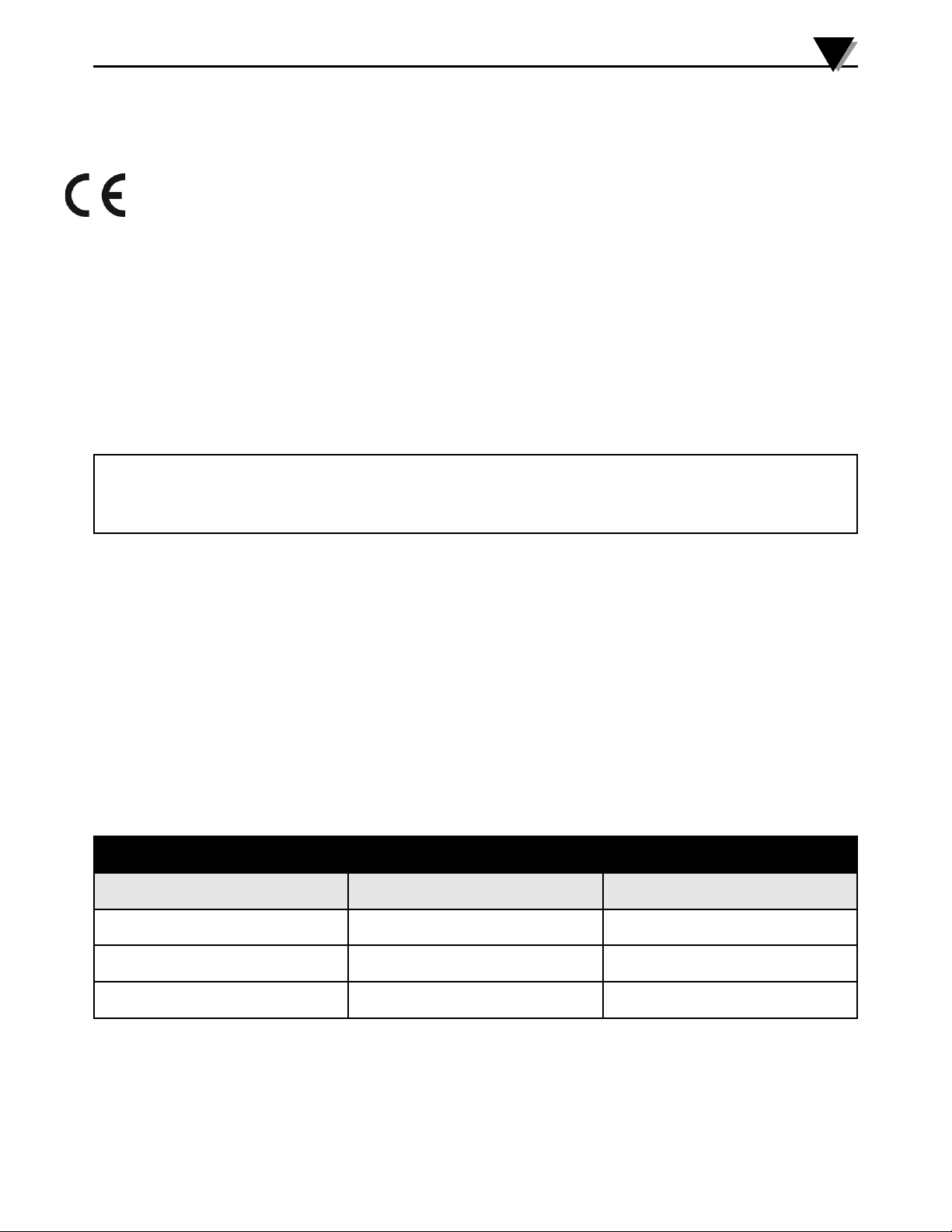
TABLE 2: ELECTRICAL CONNECTIONS
TERMINAL BLOCK I / P TRANSDUCER MODELS E / P TRANSDUCER MODELS
POSITION # 1 ( -- ) NEGATIVE SIGNAL ( + ) POSITIVE SIGNAL
POSITION # 2 NOT USED
COMMON GND FOR SIGNAL
AND SUPPLY
POSITION # 3 ( + ) POSITIVE SIGNAL ( + ) POSITIVE SUPPLY
5
Page 6
A
M4109/0719 IP510, EP510, IP511, EP511 SERIES
CALIBRATION
WARNING: In explosive atmospheres, electrical power must be removed from the transducer before attempting to
remove the cover and until the cover is fully reinstalled. Failure to do so may result in electrical spark or explosion.
CAUTION: Only attempt electrical adjustments as described below. Any mechanical adjustments made will void the
warranty.
WARNING
1. Remove the cover to gain access to the “SPAN”, (marked S), “FINE ZERO”, (marked Z) and the “DAMPING”, (3/4 turn low profile )
potentiometers. The unmarked pot “COURSE ZERO”, is used only for major calibration range changes. This adjustment should
only be attempted by factory trained personnel. For NEMA 1 enclosure, just slide open the access door on the top of the cover.
2. Set electrical input signal to 0% (e.g. 4 mA or 0 VDC ).
3. FORWARD ACTING UNITS: Using "FINE ZERO" potentiometer, adjust output pressure to 0% output (e.g. 3 psi).
4. Set electrical input signal to 100% (e.g. 20 mA or 10 VDC).
5. FORWARD ACTING UNITS: Using "SPAN" potentiometer, adjust output pressure to 100% output (e.g. 15 psi).
6. Repeat steps 2 through 5 until output pressures are properly set.
NOTE: Under certain circumstances, output pressure may exhibit cycling action. To eliminate this condition, use the “DAMPING”
potentiometer.
7. Reinstall cover using original screws and gaskets, if equipped.
MAINTENANCE
When used properly, these transducers should provide more than one million cycles without failure. If a situation should occur in
which the transducer's behavior is abnormal, the cause is usually related to a pneumatic problem.
ELECTRICAL MAINTENANCE
An electrical problem must be isolated by a skilled technician. The power source and all wiring should be checked first. Circuit board
failures are very rare, and can be confirmed by the following method. Loosen the screws, or posts that hold the circuit board in place.
Unplug the blue connector from the circuit board, and insert two small pieces of wire into the connector.
IMPORTANT: Connect a current source with the polarity as follows. Positive to the (RED) coil wire and Negative to the (BROWN) coil
wire of 10 mA to the connector, which powers the yellow coil. With supply pressure on, the unit should produce an output pressure
equivalent to 80% or more of the maximum output pressure. If there is little or no output, then the unit is clogged. Should it produce
an adequate output pressure, then the circuit board is the primary suspect. The unit must be returned to the factory for repair.
PNEUMATIC MAINTENANCE
All 510 and 511 Series transducers also have an internal orifice filter, but if contaminates do invade the transducer, they can clog the
internal orifice and block the flow, or jam open the internal supply valve. The problem can be corrected through replacement of the
orifice (see TABLE 5: KITS) or by cleaning the internal supply valve, or both.
6
Page 7

M4109/0719 IP510, EP510, IP511, EP511 SERIES
A
REPLACING ORIFICE:
This can be accomplished without removing the unit from its mounting or plumbing.
1. Turn off supply pressure and unscrew the brass orifice assembly located on the side of the housing with the gauge port.
NOTE: Small sealing o-ring may remain inside of the housing. If it does, remove it with a paper clip or some other small probe. The
replacement assembly will contain this o-ring.
2. Install the new orifice assembly making sure the o-ring is seated on the end of the screw.
CLEANING INTERNAL SUPPLY VALVE:
1. Turn off the supply pressure.
2. Use a 9/16" socket or wrench to unscrew the brass plug in the bottom of the transducer.
NOTE: Take care not to lose the supply valve spring which is retained by the bottom plug.
3. Clean out any dirt or debris and reassemble, making sure the stem of the supply valve is nested in the supply valve spring.
AGENCY APPROVALS, SPECIAL NOTES, AND CAUTIONS
INTRINSIC SAFETY
All 510 and 511 Series transducers are rated intrinsically safe by both FM and CSA for:
CLASS I, DIVISION 1, GROUPS A,B,C,D HAZARDOUS LOCATIONS.
Proper FM-approved intrinsically-safe wiring requires external FACTORY MUTUAL RESEARCH CORPORATION ENTITY-APPROVED
SINGLE-CHANNEL barriers to be selected, based upon MAXIMUM ENTITY PARAMETERS of 510 and 511 Series transducers:
ENTITY PARAMETERS:
Vmax = 28 V, Imax = 150 mA, Ci = 0.22uF, Li = 0 mH.
Voc and Isc of a barrier shall not exceed Vmax and Imax of the transducer.
(Li + Lwiring) and (Ci + Cwiring) shall not exceed La and Ca of a barrier.
NOTICE: For proper FM and CSA approved intrinsically-safe wiring, request Drawing Number 990-439-000 from the Factory.
NONINCENDIVE
All 510 and 511 Series transducers are approved as NONINCENDIVE by FM and approved as suitable by CSA for:
CLASS I, DIVISION 2, GROUP A, B, C, D HAZARDOUS LOCATIONS.
A barrier is not necessary when these transducers are in these locations.
ENCLOSURES
Compliance with NEMA 4X and CSA ENC4 enclosure ratings require that the screw-on cover has the O-ring installed. In case of a need
for replacement parts, see TABLE 3.
7
Page 8
A
M4109/0719 IP510, EP510, IP511, EP511 SERIES
EXPLOSION & DUST-IGNITION PROOF CERTIFICATIONS
FACTORY MUTUAL and CANADIAN STANDARDS ASSOCIATION
WARNING: The following ratings are valid ONLY WHEN the cover is installed for FM and CSA. BOTH the cover and
the locking device, using tamper resistant screws must be installed. Screws are to be removed and installed with a
special driver bit (supplied). In case of a need for replacement parts, follow TABLE 4.
EXPLOSION PROOF FOR CLASS I, DIV 1, GROUP B, C, D.
DUST-IGNITION PROOF FOR CLASS II, DIV 1, GROUP E, F, G.
SUITABLE FOR CLASS III LOCATIONS.
TABLE 3: NEMA 4X, REPLACEMENT COVER O-RINGS
PART NAME PART NUMBER
O-RING SEAL, VITON 214-649-000-242
O-RING SEAL, BUNA-N 214-649-000-240
TABLE 4: NEMA 4X, REPLACEMENT PARTS FOR COVER LOCKING DEVICE
PART NAME PART NUMBER
LOCKING CLAMP 224-669-000-016
TAMPER-PROOF SCREW 214-648-000-401
DRIVER BIT 010132-000
8
Page 9
M4109/0719 IP510, EP510, IP511, EP511 SERIES
TABLE 5: KITS
KIT NAME PART NUMBER
1. Panel Mounting Kit 010135-000
2. Valve Mounting Kit 010134-000
3. 2" Pipe Mounting Kit (Valve Mounting Kit is required) 010143-000
4. DIN Rail Adapter 010115-000
5. Cover Locking Device Kit (for NEMA 4X enclosure only) 010136-000
6. Zero based outlet range orifice with Buna-N O-rings 010137-000
7. Zero based outlet range orifice with Viton O-rings 010137-002
8. Standard outlet range orifice with Buna-N O-rings 010137-001
9. Standard outlet range orifice with Viton O-rings 010137-003
10. Hirschmann Connector Kit (3-prong plug, O-ring sealed) 010142-000
11. Pressure Gauge Kit, 15 PSI 010138-000
12. Pressure Gauge Kit, 30 PSI 010138-001
13. Pressure Gauge Kit, 60 PSI 010138-002
14. Pressure Gauge Kit, 160 PSI 010138-003
A
EP511 AND IP511
SIDE VIEW
TOPVIEW
SIDE VIEW
TABLE 1: WIRING TERMINATION
PWB Terminal Block I/PTransducer E/PTransducer
Position 3 Positive (+) Supply (+)
Position 2 No Connection Common
Position 1 Negative (-) Signal (+)
Drawings and dimensions are for reference only.
9
Page 10
A
M4109/0719 IP510, EP510, IP511, EP511 SERIES
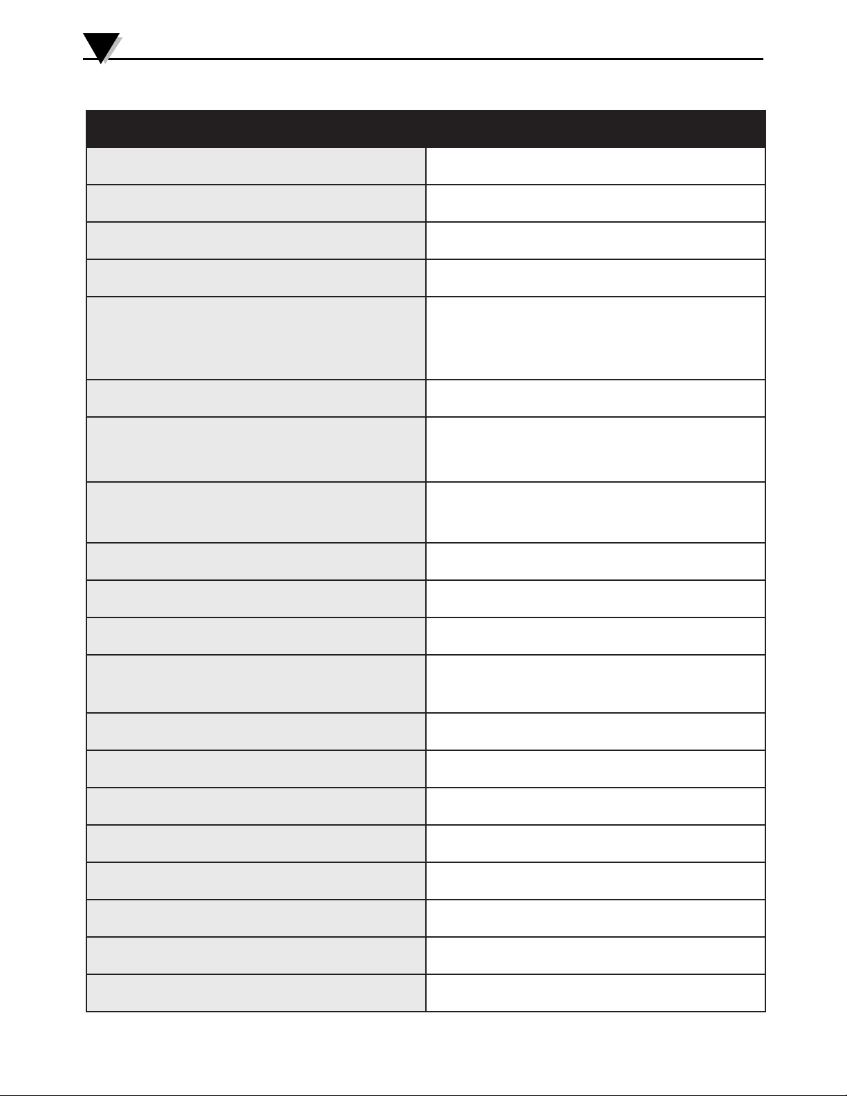
510 and 511 Series I/P AND E/P TRANSDUCER SPECIFICATIONS
Accuracy:
Hysteresis:
±0.10% of output span, typical
±0.25% of output span, maximum
0.01% of output span, typical
0.10% of output span, maximum
Dead Band: Not measurable
Repeatability:
Ambient Temperature Effect
Zero:
Span:
0.01% of output span, typical
0.10% of output span, maximum
±0.004% of nominal span per ˚F, typical
±0.022% of nominal span per ˚F, maximum
±0.013% of calibrated span per ˚F, typical
±0.022% of calibrated span per ˚F, maximum
Compensated Temperature Range: +32˚F to +122˚F
Operating Temperature Range
Buna-N elastomers:
Viton elastomers:
Storage Temperature Range
Buna-N elastomers:
Viton elastomers:
Vibration Effect:
-20˚F to 160˚F
0˚F to 160˚F
-40˚F to 200˚F
-15˚F to 200˚F
Less than 0.5% of SPAN per 1G,
5-2000 Hz, 3G maximum, 3 axes
Mounting Position Effect: Not measurable
Loop Load, I/P transducer:
Supply Voltage, E/P Transducer
Intrinsically Safe/Nonincendive:
General Purpose:
Less than 10 VDC drop at 20 mA
Less than 12 VDC drop at 50 mA
9 VDC to 28 VDC, less than 20 mA
9 VDC to 40 VDC, less than 20 mA
Supply Voltage Effect: Not measurable
Signal Impedance, E/P Transducer: 6000 Ohm minimum
RFI/EMI Effect (NEMA 4X): Less than 0.25% of SPAN, 10V/meter, 20-1000 MHz.
Supply Pressure Requirements: See TABLE 1
Supply Pressure Effect: Not measurable
Air Consumption: 6.0 SCFH maximum
Forward Flow Capacity (Supply):
Port Sizes:
Standard Range 7 SCFM
Extended Range (over 30 PSI) 12 SCFM
Pneumatic: 1/4" NPT
Electrical: 1/2" NPT
10
Page 11

Where Do I Find Everything I Need for
Process Measurement and Control?
OMEGA…Of Course!
Shop online at omega.com
TEMPERATURE
Thermocouple, RTD & Thermistor Probes, Connectors, Panels & Assemblies
Wire: Thermocouple, RTD & Thermistor
Calibrators & Ice Point References
Recorders, Controllers & Process Monitors
Infrared Pyrometers
PRESSURE, STRAIN AND FORCE
Transducers & Strain Gages
Load Cells & Pressure Gages
Displacement Transducers
Instrumentation & Accessories
FLOW/LEVEL
Rotameters, Gas Mass Flowmeters & Flow Computers
Air Velocity Indicators
Turbine/Paddlewheel Systems
Totalizers & Batch Controllers
pH/CONDUCTIVITY
pH Electrodes, Testers & Accessories
Benchtop/Laboratory Meters
Controllers, Calibrators, Simulators & Pumps
Industrial pH & Conductivity Equipment
DATA ACQUISITION
Communications-Based Acquisition Systems
Data Logging Systems
Wireless Sensors, Transmitters, & Receivers
Signal Conditioners
Data Acquisition Software
HEATERS
Heating Cable
Cartridge & Strip Heaters
Immersion & Band Heaters
Flexible Heaters
Laboratory Heaters
ENVIRONMENTAL
MONITORING AND CONTROL
Metering & Control Instrumentation
Refractometers
Pumps & Tubing
Air, Soil & Water Monitors
Industrial Water & Wastewater Treatment
pH, Conductivity & Dissolved Oxygen Instruments
M4109/0719
Page 12

WARRANTY/DISCLAIMER
OMEGA ENGINEERING, INC. warrants this unit to be free of defects in materials and workmanship for a period of 13 months from
date of purchase. OMEGA's WARRANTY adds an additional one (1) month grace period to the normal one (1) year product warranty
to cover handling and shipping time. This ensures that OMEGA's customers receive maximum coverage on each product.
If the unit malfunctions, it must be returned to the factory for evaluation. OMEGA's Customer Service Department will issue an
Authorized Return (AR) number immediately upon phone or written request. Upon examination by OMEGA, if the unit is found to be
defective, it will be repaired or replaced at no charge. OMEGA's WARRANTY does not apply to defects resulting from any action of the
purchaser, including but not limited to mishandling, improper interfacing, operation outside of design limits, improper repair, or
unauthorized modification. This WARRANTY is VOID if the unit shows evidence of having been tampered with or shows evidence of
having been damaged as a result of excessive corrosion; or current, heat, moisture or vibration; improper specification;
misapplication; misuse or other operating conditions outside of OMEGA's control. Components in which wear is not warranted, include
but are not limited to contact points, fuses, and triacs.
OMEGA is pleased to offer suggestions on the use of its various products. However, OMEGA neither assumes responsibility
for any omissions or errors nor assumes liability for any damages that result from the use of its products in accordance with
information provided by OMEGA, either verbal or written. OMEGA warrants only that the parts manufactured by the
company will be as specified and free of defects. OMEGA MAKES NO OTHER WARRANTIES OR REPRESENTATIONS OF
ANY KIND WHATSOEVER, EXPRESSED OR IMPLIED, EXCEPT THAT OF TITLE, AND ALL IMPLIED WARRANTIES
INCLUDING ANY WARRANTY OF MERCHANTABILITY AND FITNESS FOR A PARTICULAR PURPOSE ARE HEREBY
DISCLAIMED. LIMITATION OF LIABILITY: The remedies of purchaser set forth herein are exclusive, and the total liability of
OMEGA with respect to this order, whether based on contract, warranty, negligence, indemnification, strict liability or
otherwise, shall not exceed the purchase price of the component upon which liability is based. In no event shall OMEGA be
liable for consequential, incidental or special damages.
CONDITIONS: Equipment sold by OMEGA is not intended to be used, nor shall it be used: (1) as a “Basic Component” under 10 CFR
21 (NRC), used in or with any nuclear installation or activity; or (2) in medical applications or used on humans. Should any Product(s)
be used in or with any nuclear installation or activity, medical application, used on humans, or misused in any way, OMEGA assumes
no responsibility as set forth in our basic WARRANTY/DISCLAIMER language, and, additionally, purchaser will indemnify OMEGA
and hold OMEGA harmless from any liability or damage whatsoever arising out of the use of the Product(s) in such a manner.
RETURN REQUESTS/INQUIRIES
Direct all warranty and repair requests/inquiries to the OMEGA Customer Service Department. BEFORE RETURNING ANY
PRODUCT(S) TO OMEGA, PURCHASER MUST OBTAIN AN AUTHORIZED RETURN (AR) NUMBER FROM OMEGA'S CUSTOMER
SERVICE DEPARTMENT (IN ORDER TO AVOID PROCESSING DELAYS). The assigned AR number should then be marked on the
outside of the return package and on any correspondence.
The purchaser is responsible for shipping charges, freight, insurance and proper packaging to prevent breakage in transit.
FOR WARRANTY RETURNS, please have the
following information available BEFORE contacting
OMEGA:
1. P urchase Order number under which the product
was PURCHASED,
2. Model and serial number of the product under
warranty, and
3. Repair instructions and/or specific problems
relative to the product.
OMEGA’s policy is to make running changes, not model changes, whenever an improvement is possible. This affords
our customers the latest in technology and engineering.
OMEGA is a registered trademark of OMEGA ENGINEERING, INC.
© Copyright 2017 OMEGA ENGINEERING, INC. All rights reserved. This document may not be copied, photocopied,
reproduced, translated, or reduced to any electronic medium or machine-readable form, in whole or in part, without the
prior written consent of OMEGA ENGINEERING, INC.
FOR NON-WARRANTY REPAIRS, consult OMEGA for
current repair charges. Have the following information
available BEFORE contacting OMEGA:
1. Purchase Order number to cover the COST
of the repair,
2. Model and serial number of the product, and
3. Repair instructions and/or specific problems
relative to the product.
 Loading...