

Page 1
Wheatstone Bridge
In-Line Signal Conditioner
Supply Voltage: 22 to 32 Vdc
Input Current: 200 mA Start Up
(90 mA max)
Current Outputs: 4-20 mA,
12 mA zero ± 8 mA
Voltage Outputs:
0-5, 0-10, ±5, ±10 Vdc
IN-UVI Series
U Wide Range of Field
Selectable Inputs and
Outputs
U Input/Output Isolation
U Low Thermal Drift
U IP65 Protected
U Rugged Stainless Steel
Enclosure
U Ideal for Use with
Miniature Transducers or
When Space is Limited
U Improved Signal to
Noise Ratio
U Signals Can Be Sent
Over Much Longer
Distances than Millivolt
Signals
Typical Applications that
Require an In-Line Signal
Conditioner:
U When a Transducer is
Located in a Hostile
Environment* or Some
Distance From the
Display
U Potentiometer
Adjustments (Which are
Located in the Signal
Conditioner) are More
Conveniently Located
and More Accessible
than the Transducer
Itself
* If the environment at the sensing site is
subject to high temperatures, humidity, or
corrosive conditions, it may be necessary
to place the in-line signal conditioner away
from the transducer.
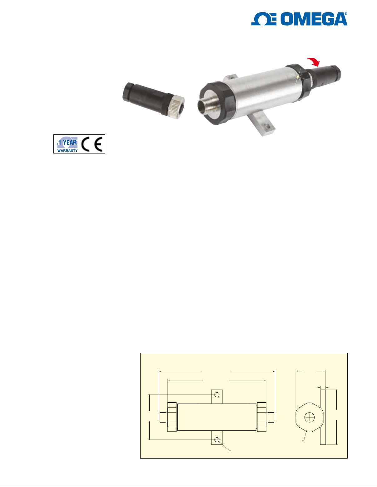
M12 connector accessory,
shown smaller than actual size
Application Examples:
U Monitor Compression
Forces of an Automated
Clamping Machine that
Modifies 44 Assembly
Pieces at a Time by
Automated Drills
U Monitor Forces Needed
to Raise the Roof of
an Aviation Hanger for
Larger Airships to Fit
Inside
The OMEGA IN-UVI in-line signal
conditioner is housed in a rugged
stainless steel enclosure, which is
connected between the transducer
and a readout instrument. The
signal conditioner supplies a highly
regulated bridge excitation voltage
for the transducer and converts the
millivolt signal of the transducer to
0 to 5, 0 to 10, ±5, ±10 Vdc or
4 to 20, 12 ± 8 mA.
The IN-UVI features include two
selectable excitation voltages,
programmable gain amplifier for
134.8 (5.306)
114.3 (4.50)
52.3
(2.06)
1
signals from 0.5 mV/V to 4 mV/V,
wide zero adjustment range and
an isolated shunt calibration relay
for quick field setup. All output
options and excitation voltages
are field selectable.
Specifications
Supply Voltage: 22 to 32 Vdc isolated
from output
Isolation Input to Output: 500 Vdc
Capacitance: 0.022 µF
Resistance: 100 MΩ
Input Current: 90 mA maximum
(must be capable of supplying
200 mA)
Voltage Output: ±5 volts, ±10 volts at
2 mA maximum
Output Resistance: 60 Ω
Noise: 10 mV peak to peak @ 3 mV/V
voltage mode (10 Vdc) 20 uA peak to
peak current mode
Short Circuit Protection: Yes +output
to -output
Current Output: 4 to 20 mA, 12 mA
zero ±8 mA outputs field
programmable
Maximum Load Resistance: 700 Ω
at 20 mA
Operating Temperature: -20 to 60°C
(0 to 140°F)
ø5.4 (0.213)
IN-UVI, shown smaller
than actual size, with one
M12 accessory connector.
Dimensions: mm (in)
34.8
(1.37)
6.35
(0.250)
63.5
(2.501)
ø31.2 (1.23)
Page 2
Response Time: 200 uS (0 to 63%)
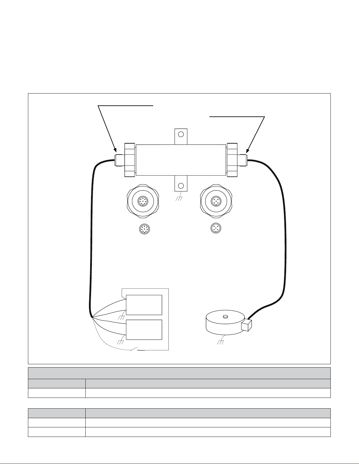
SENSOR WIRING
PIN 1 = + SUPPLY
MODEL: IN-UVI INLINE AMPLIFIER
PIN 1 = + EXC
PIN 2 = - EXC
PIN 3 = + SIG
PIN 4 = - SIG
PIN 5 = SHIELD
PIN 2 = RETURN
PIN 3 = + OUTPUT
PIN 4 = - OUTPUT
PIN 5 = SHUNT CAL
PIN 6, PIN 7 = NC
PIN 8 = CASE
SUPPLY RANGE: 22 TO 32 VDC @ 200 mA
SERIAL NO:
STAMFORD, CT 04907-0047 USA
5 CENTER PIN
1
2
3
4
1
2
3
456
7
8 CENTER PIN
XXXXXXX
VI
CS
FS
Z
Excitation Voltage: 5 or 10 Vdc field
programmable
Excitation Max Current: 30 mA @
10 Vdc
Sensor Input Range: 0.5 mV/V to 4
mV/V in 0.5 steps
Shunt Cal: Yes; remotely activated
Environmental Protection: IP65
Long Term Zero Drift: 0.1% of FS/year
Temperature Effects:
Zero: 0.001%/°F (Auto zero front end)
Span: 0.0025%/°F
Linearity: 0.01%
Adjustment Range:
Zero: ±30%
Span: ±20% fine ±40% coarse
Adjustment Location: Behind
connector endcaps
EMC Effect: <0.15% of FS per
EN61326-1 (industrial)
Dimensions:
134.8 L x 34.8 H x 31.2 mm D
(5.3 x 1.37 x 1.23)
Transducer Requirements:
Bridge Excitation: 5 Vdc or 10 Vdc
Bridge Sensitivity: 1 to 8 mV/V @
5 Vdc EXC, 0.5 to 4 mV/V for
10 Vdc EXC
Bridge Resistance: 350 to 5000 Ω*
* Time constant 0 to 63% (200 µS for a
350 Ω bridges/1.2 mS for a 5000 Ω bridge)
NOTE: There are TWO different connectors offered as ACCESSORIES:
1. Model No: M12.8-S-F-FM
Description: 8-Pin M12 Connector with Cable Gland, Input/Output Connection
2. Model No: M12.5-S-F-FM
Description: 5-Pin M12 Connector with Cable Gland, Sensor Connection
4
1
5 CENTER PIN
3
2
456
7
3
2
1
8 CENTER PIN
8 CENTER PIN
8 PIN M12
8 PIN M12
PIN 1 = + SUPPLY
PIN 1 = +SUPPLY
PIN 2 = SUPPLY RETURN
PIN 2 = SUPPLY RETURN
PIN 3 = +OUTPUT
PIN 3 = + OUTPUT
PIN 4 = -OUTPUT
PIN 4 = – OUTPUT
PIN 5 = SHUNT CAL 1
PIN 5 = SHUNT CAL1
PIN 6 = N/C
PIN 7 = N/C
PIN 6 = N/C
PIN 8 = SHIELD
PIN 7 = N/C
PIN 8 = CASE/SHIELD
5 CENTER PIN
M12 CONNECTOR
M12 CONNECTOR
PIN 1 = + EXCITATION
PIN 1 = +EXCITATION
PIN 2 = – EXCITATION
PIN 2 = -EXCITATION
PIN 3 = +INPUT
PIN 3 = + INPUT
PIN 4 = -INPUT
PIN 4 = – INPUT
PIN 5 = SHIELD
PIN 5 = SHIELD
SHUNT CAL RESISTOR (INTERNAL CONNECTOR)
SHUNT CAL RESISTOR
(INTERNAL CONNECTOR)
REMOTE SHUNT CAL SW
CLOSE SWITCH TO ENABLE
To Order
Model No. Description
IN-UVI
Accessories
Model No. Description
M12.5-S-F-FM
M12.8-S-F-FM
Wheatstone bridge in-line signal conditioner
5-pin M12 connector with cable gland, sensor connection
8-pin M12 connector with cable gland, input/output connection
+
POWER SUPPLY
POWER SUPPLY
28 VDC @ 200 mA
28 VDC @ 200 mA
MINIMUM
MINIMUM
-
+
DATA SYSTEM
DATA SYSTEM
OR DISPLAY
OR DISPLAY
-
REMOTE SHUNT CAL SW
CLOSE SWITCH TO ENABLE
STANDARD LOAD CELL OR
STANDARD LOAD CELL OR PRESSURE SENSOR
PRESSURE SENSOR
2
Page 3
Standard Cable Part Numbers
To Order
Connector
Model No.
Sensor Side
CA-4PC24-2A-015-INUVI P001268 M12.5-S-F-FM LC111 25-200 lbs
CA-4PC24-3-015-INUVI
PT06F10-6S M12.5-S-F-FM LC1011, LC1112, LC1113, LC411, LC412,
CA-4TE24-3-015-INUVI PT06F10-6S M12.5-S-F-FM PX35, PX01, PX02, PX80, PX81
CA-4PC24-4-015-INUVI
PT06F10-6S M12.5-S-F-FM LCHD 5 to 5000 lbs, PX610, PX61V1, PX931
CA-4PC24-4A-015-INUVI MS3106E-14S-6S M12.5-S-F-FM
CA-4TE24-5-015-INUVI PT06F10-6S M12.5-S-F-FM PX32
CA-4TE24-6-015-INUVI
PT06F10-6S M12.5-S-F-FM
CA-4PC24-8-015-INUVI PT06F10-6S M12.5-S-F-FM PX429, 3 mV/V
CA-4PC24-0-015-INUVI STYLE 2 M12.5-S-F-FM Style 2 - Wiring Code 0
CA-4TE24-0-015-INUVI STYLE 2 M12.5-S-F-FM Style 2 - Wiring Code 0
Flying Leads
Model No.
Input/Output Side
CA-6PC24-OUT-015-INUVI STYLE 2 M12.8-S-F-FM Style 2 - Wiring Code OUT
Connector
IN-UVI Side
Connector
IN-UVI Side
Examples of Product Used on (Contact
Sales for Products Not Listed)
LC711, LC712, LC511, LC315, LC213,
LC214, LC111 >200 lbs
LCHD > 5000 lbs (uses MS3102E-14S-6P)
(mV) PX5000, PX5500, PX6000 (mV output),
PX1004, PX1005
Examples of Product Used on (Contact
Sales for Products Not Listed)
T
R
A
N
S
D
U
C
E
R
S
I
D
E
SHIELD
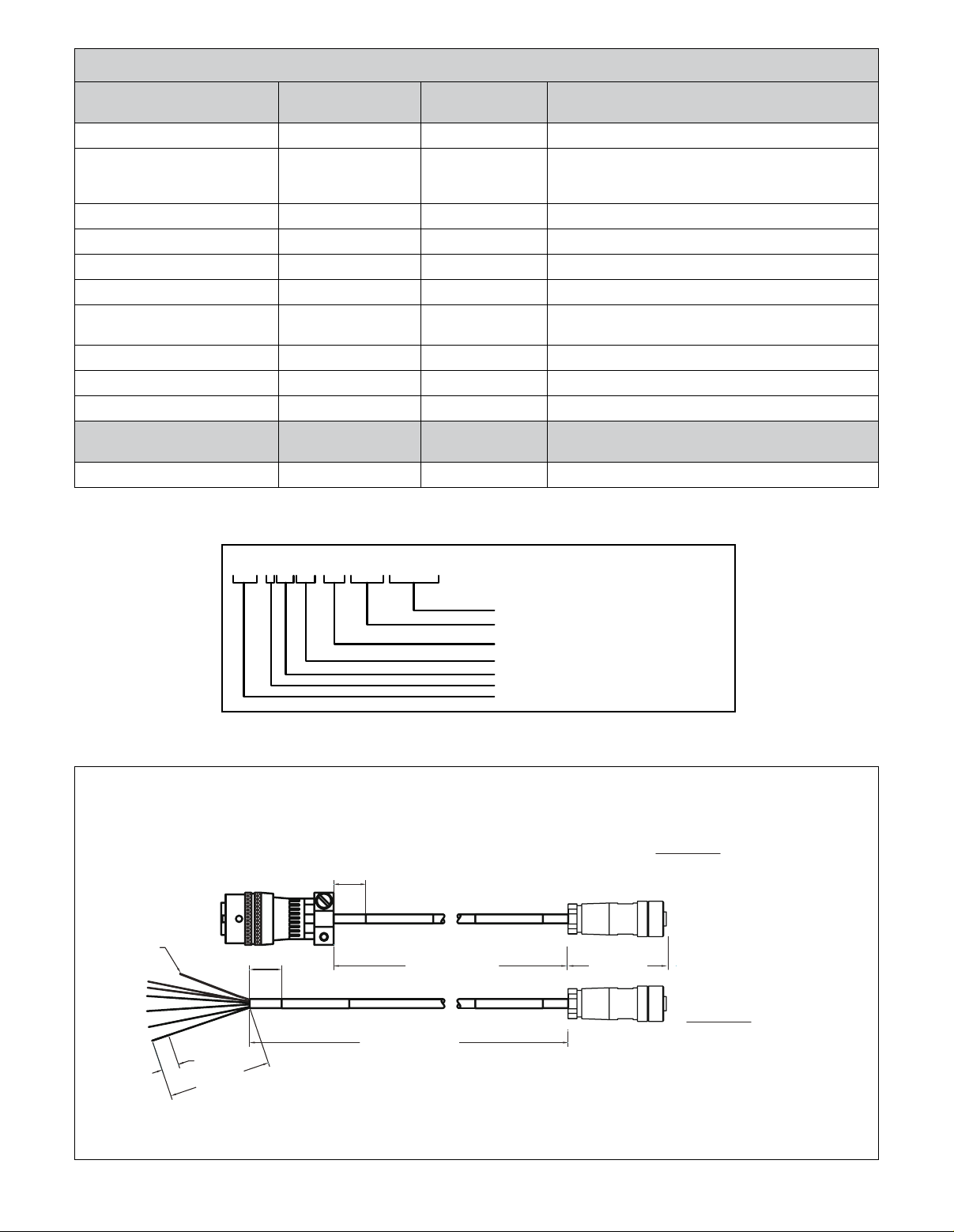
Definition of Cable part number
CA-4PC24-2A -xxx -INUVI
CABLE DESIGNATION
LENGTH, L (FT)
WIRING CODE
GAGE OF CONDUCTORS (24AWG, ETC.)
CABLE (PC=PVC) (TE=FEP)
NO. OF CONDUCTORS
CABLE ASSEMBLY
Insulation Type Temperature Rating: FEP = -55 to 125°C (-67 to 257°F), PVC = -30 to 80°C (-22 to 176°F)
IN-UVI Cable Assembles to Connect Transducer via Connector or Flying Leads.
STYLE 1
ALL WIRING CODES EXCEPT 0.
DUAL CONNECTOR ENDS.
STYLE 2
WIRING CODE 0 ONLY.
FLYING LEADS WITH A CONNECTOR.
Dimensions: mm (in)
13
(0.5)
152 (6)
13 (0.5)
13 (0.5)
LENGTH IN FEET
LENGTH IN FEET
45 (1.75)
TYP
I
N
U
V
I
S
I
D
E
3
Page 4
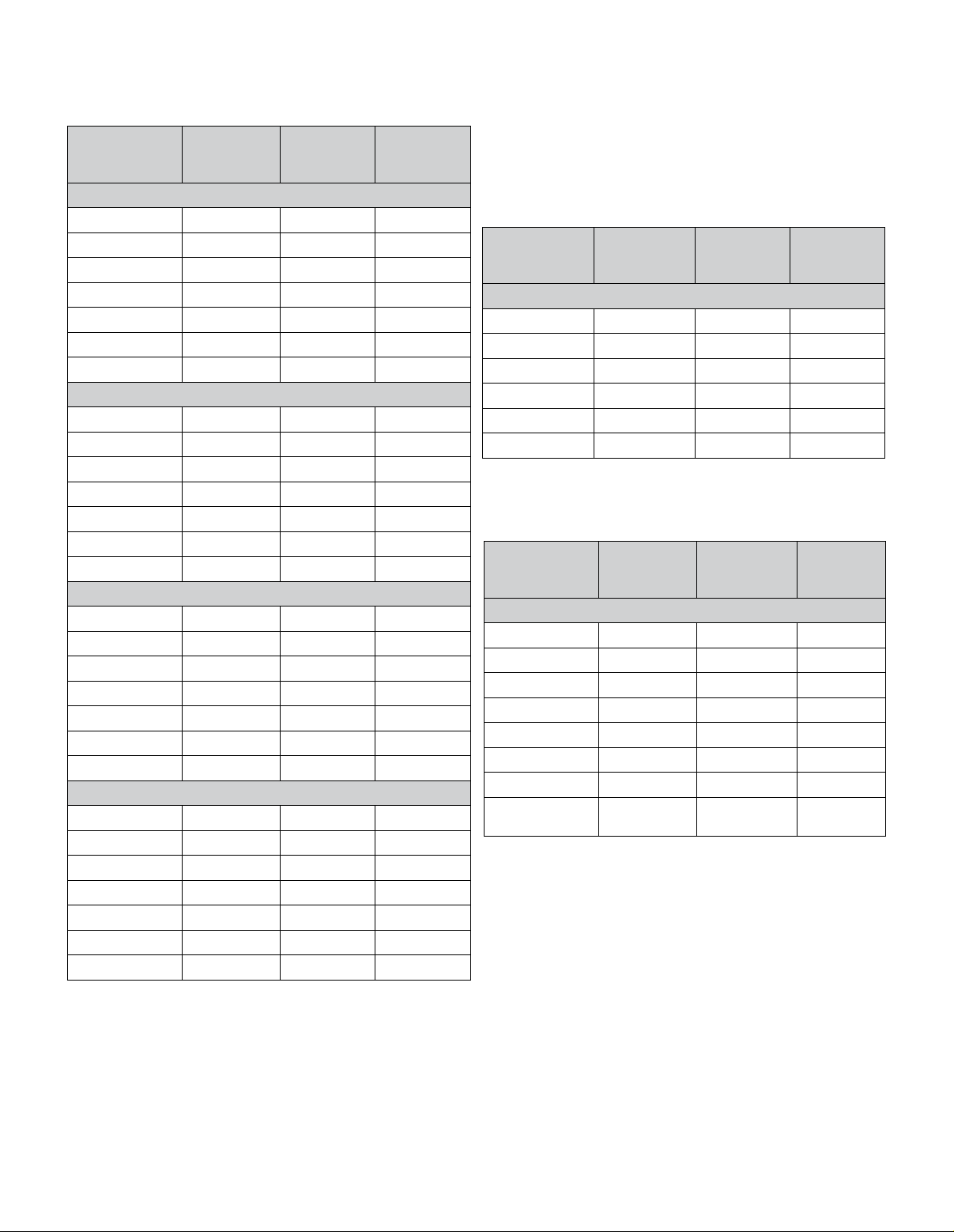
IN-UVI Wiring Codes
Dual Connector Ends, All Wiring Codes Except 0
Connector Pin
Transducer
Side
A GREEN + Signal 3
B WHITE - Signal 4
C BLACK - Excitation 2
D RED + Excitation 1
E – – –
F – – –
– – Shield* 5
A RED + Excitation 1
B – – –
C BLACK - Excitation 2
D – – –
E WHITE - Signal 4
F GREEN + Signal 3
– – Shield* 5
A RED + Excitation 1
B GREEN + Signal 3
C WHITE - Signal 4
D BLACK - Excitation 2
E** – – –
F** – – –
– – Shield* 5
A RED + Excitation 1
B BLACK - Excitation 2
C GREEN + Signal 3
D WHITE - Signal 4
E** – – –
F** – – –
– – Shield* 5
** No connection for transducer Pins E & F.
CA*INUVI
Wiring Code
Wiring Code 2A/3
Wiring Code 4/4A
Wiring Code 5/6
Wiring Code 8
Connection
IN-UVI
Connector
Pin
IN-UVI Side
Flying Leads with Connector on IN-UVI End
Connector Pin
Transducer
Side
N/A RED + Excitation 1
N/A BLACK - Excitation 2
N/A GREEN + Signal 3
N/A WHITE - Signal 4
N/A – Shield* 5
N/A – – –
NOTE: Excitation of IN-UVI connects to input of transducer,
and output of transducer connects to signal of IN-UVI.
Flying Leads with Connector
Connector Pin
Transducer
Side
N/A RED + Supply 1
N/A BLACK - Supply 2
N/A GREEN + Signal 3
N/A WHITE - Signal 4
N/A BLUE
N/A – – 6
N/A – – 7
N/A
* Shield not connected to Connector Sensor Side or Transducer.
CA*INUVI
Wiring Code
Wiring Code 0
CA*INUVI
Wiring Code
Wiring Code OUT (8-Pin)
BROWN/
SHIELD*
IN-UVI
Connection
IN-UVI
Connection
Shunt Cal En
Case 8
Connector
Pin
IN-UVI Side
Connector
Pin
IN-UVI Side
5
4
 Loading...