

Page 1
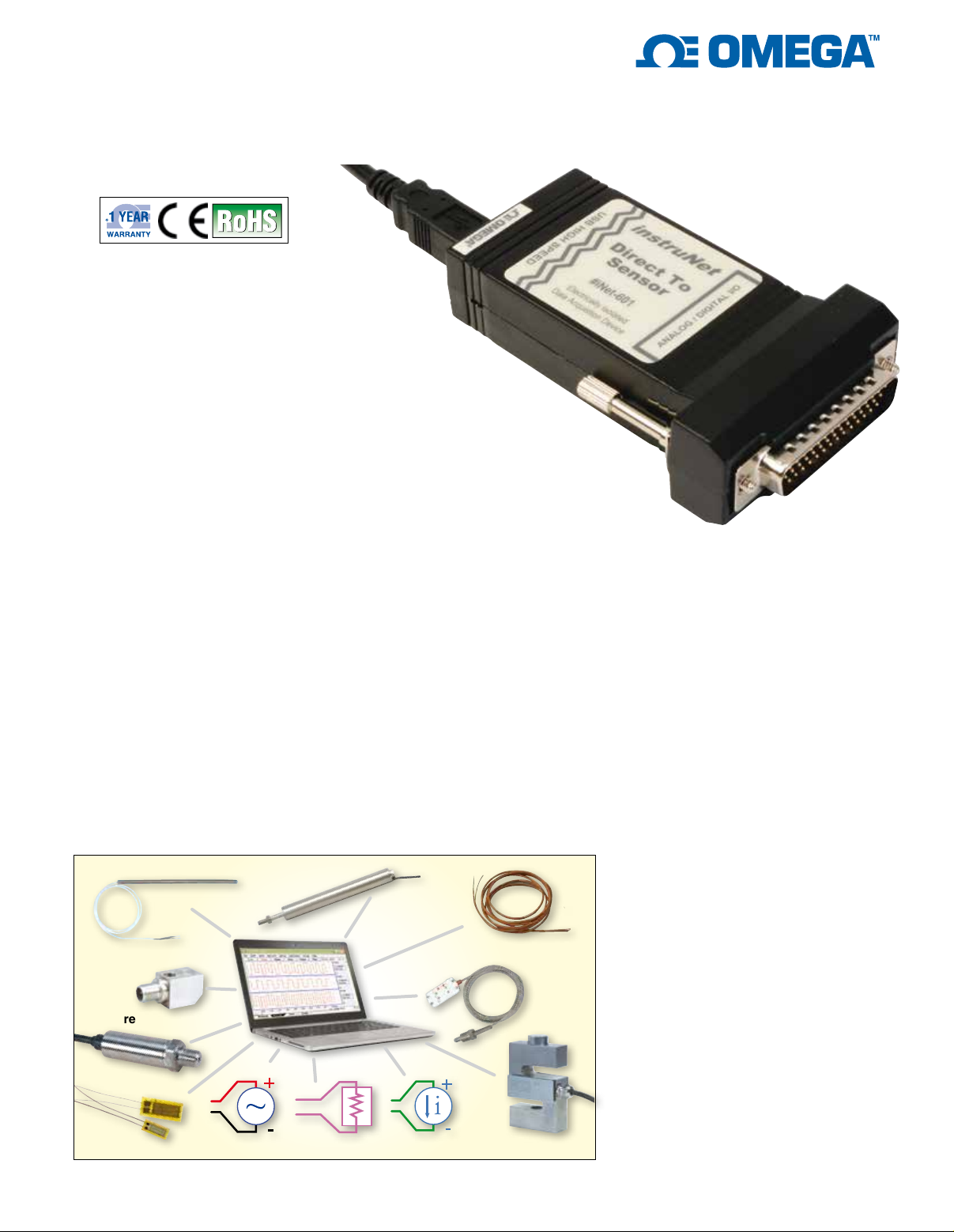
High Accuracy
Direct-to-Sensor
USB Data Acquisition System
iNET-600 and iNET-601
iNET-601 shown
smaller than actual size.
U 16SE/8DI Voltage Input
Channels with Extremely
Accurate 24-Bit A/D
Converter that Supports
±20 mV to ±10V Ranges
U 4 Digital I/O (4 mA Sink/
Source, 0 to 3.3V)
U
Controls Process via
Windows® Software Using
Analog Inputs and Digital I/O
U iNET-601 Provides ±36V
Input Bank to USB
Electrical Isolation
U iNET-600 Connects I/O
Signal Ground to
Computer Ground
U Receives Power from the
USB Bus and Provides
Excitation Power (+3.3V,
80 mA) to Sensors
U Easily Set-Up Sensors
Using the Included
instruNet World Software
U Connect a Computer
Directly to Sensors:
Voltage, Thermocouple,
Thermistor, RTD, Load Cell,
Strain Gage, Potentiometer,
Current, Resistance
LVDT
Thermistor
Accelerometer
Pressure
Strain
Voltage
Resistance
The iNET-600
Series A/D module
provides 16SE/8DI
voltage input channels
(Ch#1...#16), each of which
are independently software
programmable with Windows
software that support the direct
connection to many common sensor
types. Voltage input range on each
channel is independently software
programmable to one of: ±20 mV,
±40 mV, ±80 mV, ±150 mV, ±300 mV,
±600 mV, ±1.2V, ±2.5V, ±5V, ±10V.
Included is a mating Hd44 Female
Connector and Cover. Alternatively,
you can attach iNET-600 Series to
the following optional wiring boxes:
iNET-500, iNET-511, iNET-512. If
you are working with thermocouples,
an iNET-510 wiring box is required
due to its internal cold junction
compensation.
iNET-600 Series is a stand-alone
USB data acquisition system. No
additional components, such as
external power supply, are required.
Included in the box: iNET-600 Series
Hardware Device, USB Cable,
Software on CD, Mating Hd44
Female Connector and Hd44 Cover.
Thermocouple
RTD
Current
Load cell
1
Digitize at a maximum sample rate
of 160K sample/sec for 1 channel,
16Ks/sec/ch for 2 channels, 8Ks/
sec/ch for 4 channels, and 4Ks/sec/
ch for 8 channels. Maximum sample
rate is for ±5V input signal. For
accuracy and sample rate details
on all supported input signals,
see the tables at the end of the
spec sheet.
Each channel provides the following
software programmable parameters:
A/D Signal-Averaging-Per-Point (0 ...
100 mSec), Sample-Rate (samplesper-second-per-channel), Digital
IIR Filter (Low Pass, High Pass,
Band Pass, or Band Stop), Voltage
Measurement Range (±20 mV to
±10V), Sensor Type, and SingleEnded or Differential Wiring.
Excitation power (+3.3V ±0.2V,
<80 mA, 28 mA per sensor max)
is provided for sensors, along with
other End User Power voltages.
This 3.3V, which is referenced to
instruNet Ground, is automatically
read back by A/D when calculating
sensor values.
The 4 mA sink/source digital I/O
port consists of 4 individual TTLcompatible lines (Ch#25...#28),
each of which can be configured as:
input or output bit. When configured
as an input, a channel can be used
to sense a digital high (2 to 5.5V)
or digital low (0V to 0.8V). When
configured as an output, a channel
Page 2
can be set high (e.g. >2V) or low (e.g.
<0.8V). These I/O pins are short-circuit
protected against high
voltages up to
6.0V and down to -6.0V.
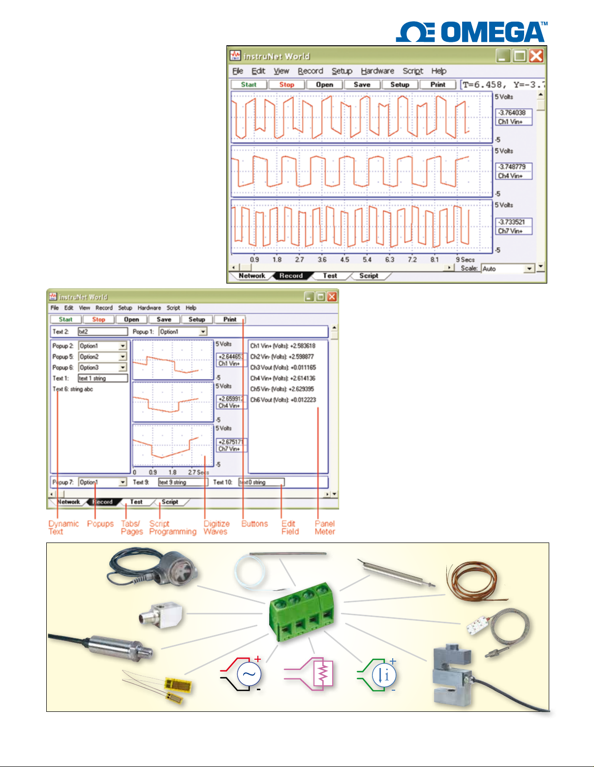
Digitize and Plot Waveforms
in Real-time
Waveforms are recorded in one long
continuous stream (strip chart mode);
or they are digitized in short segments
where each segment begins after a
specified trigger event (oscilloscope
mode). Any one of the instruNet analog
or digital input channels can be used
as a trigger. Data is either placed into
RAM memory, a file on disk, or is
deleted after being plotted. One uses
the Setup dialog box to set the sample
rate (i.e. points-digitized-per-secondper-channel) and number of points
digitized; and uses the Network page
to select which channels are digitized.
After setting up the system; one can
press the Network Save button to save
the setup, press the Start button to start
digitizing, press the Stop button to stop it,
press the Record Save button to save waves
in RAM to disk (post-acquisition), and press
the Open button to load waves from disk for
viewing.
Free instruNet World Software
instruNet World Software is a FREE
application program that manages, monitors
and operates instruNet data acquisition and
control hardware. Additionally, it digitizes long
continuous waveforms, spools them to disk,
views incoming waveforms in real-time and
then allows post acquisition viewing, like an
oscilloscope or strip chart recorder.
Download free instruNet Software
to Learn More
If you want to learn more about instruNet
software, you can download it for free from
instruNet World PLUS software adds valuable features
to the FREE instruNet World (not PLUS) software.
Flow
Accelerometer
Pressure
Strain
Connect Directly to Thermocouple, RTD, Thermistor, Strain Gage, Load Cell, Voltage, Current, Resistance and Accelerometer Inputs.
Voltage
Thermistor
Resistance Current
2
LVDT
Thermocouple
RTD
Load cell
Page 3
the OMEGA website and do the
tutorial with
exe”.
This program is the same
as “instruNet World.exe”, except
it generates a random number
instead of reading the A/D.
“instruNet World Demo.
Optional instruNet World
PLUS (iNET-IWPLUS)
Software
instruNet World PLUS
(iNET-IWPLUS) is a reasonably
priced yet powerful and easyto-use data acquisition software
program for Windows. It enables
you to digitize, plot, control,
analyze, and save to disk A/D,
and digital I/O data from instruNet
hardware. Additionally, it enables
you to define your own instrument
front panel with buttons, popup
menus, edit fields, dynamic text,
text editor regions, and waveform
graphs; as illustrated on the
right. instruNet World PLUS
is programmed with a simple
script language that can define
tasks such as control loops. For
example, one can type “Dio1 =
OnOff (Ain1, 3)” to define Dio #1
as a function of A/D #1.
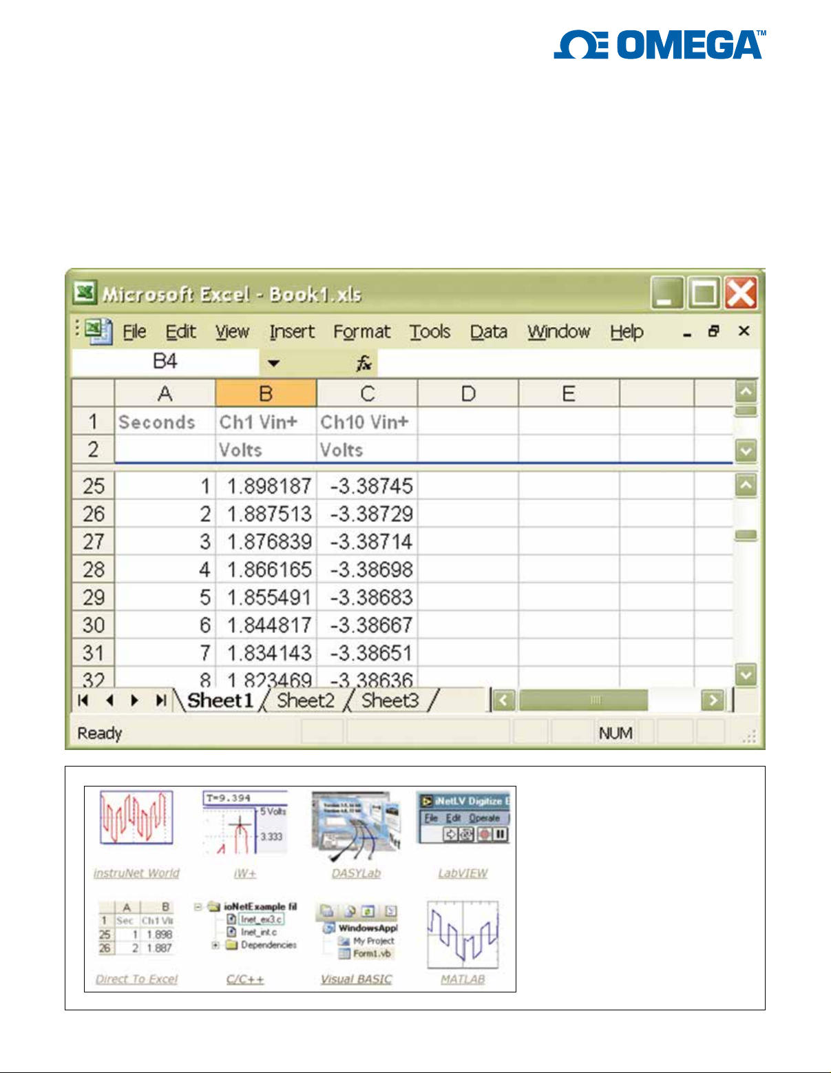
Digitize Directly into
Excel® Spreadsheet
Application Software
instruNet is compatible with Excel,
LabVIEW®, DASYLab®, MATLAB,
Origin, C & Visual BASIC software.
Application software is used to
configure all I/O channels, store
your settings, view digitized data
in real-time, analyze, stream data
to disk, and scroll through your
waveform post-acquisition.
3
Page 4
As illustrated on the right, the
instruNet World PLUS software
package includes “Direct To Excel.
exe” software, which populates an
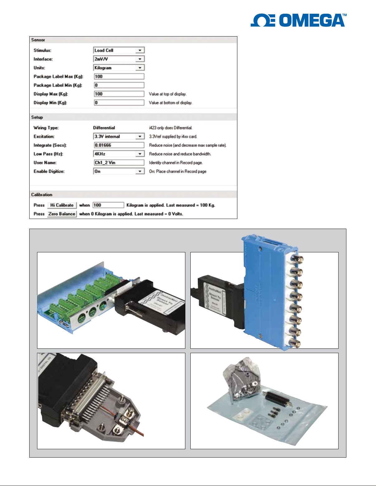
Wiring to Sensors
The following photos show several methods for attaching to sensors:
iNET-600 Series attached to
optional iNET-512 wiring box.
End user solders sensor
wires directly to mating Hd44
connector/hood included
with iNET-600 Series.
iNET-600 Series
attached to optional
iNET-511 BNC wiring box.
Mating Hd44 female
connector, Hd44 cover
and hardware assembly kit
included with iNET-600 Series.
4
Page 5
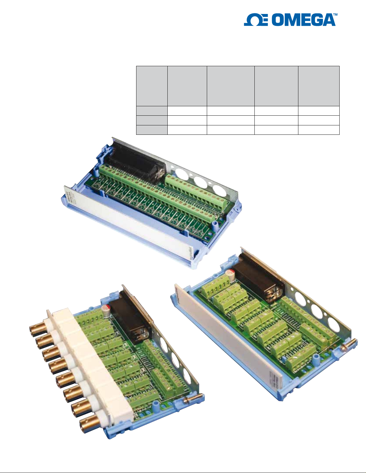
Optional Wiring Boxes
iNET-510, iNET-511, iNET-512
wiring boxes easily bolt to
iNET-600 Series devices. The
iNET-510 is the simplest, is
the lowest cost, and supports
thermocouples. The iNET-511
includes 8 BNC connectors. The
iNET-512 has a vRef/2 source that
is used to help complete ¼ bridge
and ½ bridge strain gage circuits. If
you are measuring thermocouples,
then the iNET-510 is the only wiring
box that will work, since it contains
an internal temperature sensor that
measures the temperature of the
iNET-510 screw terminals.
Model
iNET-510
iNET-511
iNET-512
1
⁄4 and 1⁄2
bridge strain
BNC
connectors
Thermocouple
support
gage vRef/2
support
0 yes no no
8 no no yes
0 no yes yes
Individual
banks
of screw
terminals
for each
sensor
iNET-510
iNET-512
iNET-511
5
Page 6
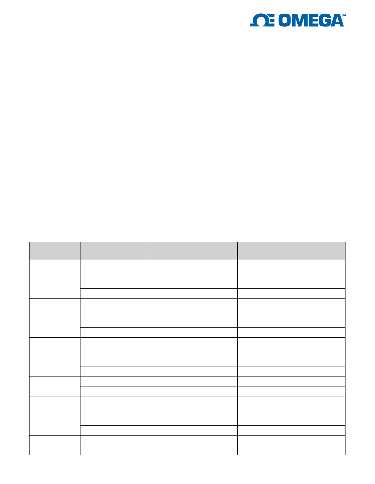
Specifications
ANALOG INPUTS
Number of Channels: 16 single-ended
(SE)/8 differential (DI)
A/D Converter: 24-bit when averaging
each point for ≥1m sec; and 16 bits
when not averaging
Voltage: See voltage accuracy/range
charts
Voltage Ranges: ±20 mV, ±40 mV,
±80 mV, ±150 mV, ±300 mV, ±600 mV,
±1.2V, ±2.5V, ±5V, ±10V
Electrical Isolation (iNET-601 Only):
±36 Vdc bank isolation
Protected Voltage: ±30 Vdc with
power on or off
RFI Filter: 13 KHz RFI filter on
≤ ±150 mV range
Digital Filter: Low Pass, High Pass,
Band Pass, or Band Stop
Digital Filter Type: Elliptic, Chebyshev
B, Chebyshev S, or Butterworth
Common Mode Voltage: ±10 Vdc
Common Mode Rejection Ratio:
≥110dB (0 to 60 Hz)
Input Impedance: 100 MΩ
SENSOR MEASUREMENT
Thermocouple: J/K/T/E/R/S/B/N/C/G/D
Thermistor: 2252 Ω
(OMEGA 44000 Series), custom
RTD: 100 Ω, 500 Ω, 1 kΩ platinum
Load Cell: 10 kg, 25 kg, 100 kg,
250 kg, 1000 kg, 5000 kg, custom
Strain: 120 Ω or 350 Ω.
half bridge or full bridge; internal
i60x voltage reference supports a
maximum of three 120 Ω bridges; and
eight 350 Ω bridges
Potentiometer: 1 to 50 kΩ
Current: ±80 uA, ±120 uA, ±500 uA,
±600 uA, ±800 uA, ±1.2 mA, ±2.5 mA,
±12 mA, ±24 mA, 0 to 24 mA, custom
Resistance: 0 to 33 Ω, 0 to 100 Ω,
0 to 330 Ω, 0 to 1 kΩ, 0 to 3300 Ω,
0 to 10 kΩ, custom
LVDT/Flow/Pressure: Current,
voltage, mV/V
1
⁄4 bridge,
DIGITAL I/O
Number of Channels: 4 digital I/O
(4 mA sink/source, 0 to 3.3V)
“0” Input Voltage: 0 to 0.8 Vdc
“1” Input Voltage: 2 to 5.5 Vdc
“1” Input Current: Amps = V
(“1” must drive internal 50 kΩ pulldown resistor)
“0” Output Voltage: <0.7 Vdc @
<2 mA; < 0.9 Vdc @ 4 mA
“1” Output Voltage: 2.2 to 3.3 Vdc @
4 mA
Pull-Down Resistor: 50 kΩ ±1%
/ 50 kΩ
in
ENVIRONMENTAL
Operating Environment: 1 to 70°C
(34 to 158°F), <90% RH,
no condensation
Storage Temperature: -20 to 70°C
(-4 to 158°F)
POWER
Power Consumed From USB Cable:
+5 Vdc 255 mA typical (433 mA max)
Voltage Reference At Hd44
Connector: 3.30 Vdc (80 mA)
Unregulated Power Available to
User At Hd44 Connector: 5 Vdc
(8 mA), ±15 Vdc (4 mA)
MECHANICAL
Material: Plastic enclosure
Dimensions: 58 H x 96 W x 24 mm D
(3.784 x 0.924 x 2.286")
Weight: 454 g (1 lb)
Mounting: Place on desktop, attach to
wall, or place inside another enclosure
(OEM)
Voltage Range/Accuracy
Signal Averaging
Voltage Range
±10V
±5V
±2.5V
±1.2V
±600 mV
±300 mV
±150 mV
±80 mV
±40 mV
±20 mV
1
Per Point
Absolute Accuracy
(Max Gain + Offset Error)
Max Multi-Channel Aggregate
Sample Rate (s/sec/agg)
0 mSec ±(0.005% + 1569.9 μV) 33.40K
1.0 mSec ±(0.005% + 271.8 μV) 0.77K
0 mSec ±(0.005% + 709.4 μV) 33.40K
1.0 mSec ±(0.005% + 131.6 μV) 0.77K
0 mSec ±(0.005% + 374.2 μV) 25.49K
1.0 mSec ±(0.005% + 69.2 μV) 0.76K
0 mSec ±(0.005% + 197.3 μV) 25.26K
1.0 mSec ±(0.005% + 37.2 μV) 0.76K
0 mSec ±(0.005% + 123.9 μV) 20.86K
1.0 mSec ±(0.005% + 22.4 μV) 0.75K
0 mSec ±(0.005% + 90.9 μV) 20.71K
1.0 mSec ±(0.005% + 15.3 μV) 0.75K
0 mSec ±(0.005% + 70.4 μV) 3.75K
1.0 mSec ±(0.005% + 11.4 μV) 0.69K
0 mSec ±(0.005% + 49.3 μV) 3.75K
1.0 mSec ±(0.005% + 8.6 μV) 0.68K
0 mSec ±(0.005% + 32.8 μV) 3.58K
1.0 mSec ±(0.005% + 6.7 μV) 0.68K
0 mSec ±(0.006% + 32.1 μV) 3.58K
1.0 mSec ±(0.006% + 6.5 μV) 0.68K
6
Page 7
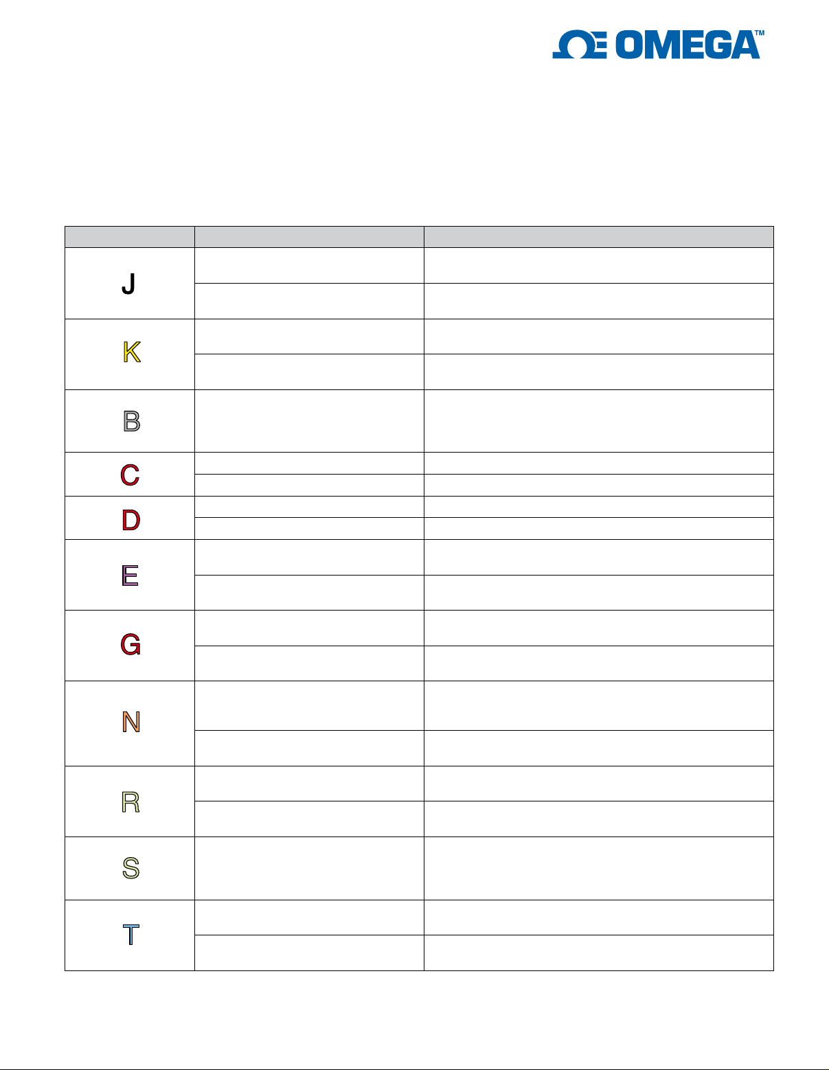
Thermocouple (Requires iNET-510 Wiring Box)
1,2
Thermocouple Measurement Range Absolute Accuracy (≥100 µSec Averaging Per Point)
-210 to 150°C
J
-210 to 1200°C
-200 to 200°C
K
-200 to 1360°C
-10 to 150°C: ±0.79°C
-210 to -10°C: ±1.15°C
10 to 1200°C: ±0.90°C
-210 to 1200°C: ±1.40°C
-10 to 120°C: ±0.87°C
±200°C: ±1.31°C
10 to 1360°C: ±1.16°C
-200 to 1360°C: ±1.62°C
251 to 600°C: ±4.75°C
B 251 to 1820°C
600 to 1300°C: ±2.45°C
251 to 1300°C: ±4.75°C
1300 to 1820°C: ±1.63°C
C
D
E
G
0 to 1K°C ±1.84°C
0 to 2315°C ±2.48°C
0 to 1K°C ±2.14°C
0 to 2315°C ±2.48°C
-200 to 125°C
-200 to 1K°C
0 to 500°C
0 to 2315°C
-90 to 80°C: ±0.80°C
-200 to 125°C: ±1.01°C
10 to 1K°C: ±0.81°C
-200 to 1K°C: ±1.20°C
0 to 500°C: ±6.30°C
100 to 500°C: ±3.23°C
0 to 300°C: ±6.44°C
300 to 2315°C: ±1.86°C
-200 to 0°C: ±1.66°C
-200 to 570°C
N
-200 to 1300°C
-50 to 800°C
R
-50 to 1768°C
0 to 170°C: ±1.01°C
-10 to 570°C: ±1.01°C
10 to 1300°C: ±1.17°C
-200 to 1300°C: ±2.14°C
-50 to 10°C: ±3.41°C
10 to 800°C: ±2.49°C
10 to 1768°C: ±2.55°C
-50 to 1768°C: ±3.48°C
-50 to -10°C: ±3.17°C
S -50 to 1768°C
-10 to 860°C: ±2.66°C
-50 to -10°C: ±3.17°C
-10 to 1768°C: ±2.66°C
-200 to 175°C
T
-200 to 400°C
-200 to -10°C: ±1.27°C
-10 to 175°C: ±0.86°C
10 to 400°C: ±0.84°C
-200 to 400°C: ±1.29°C
7
Page 8
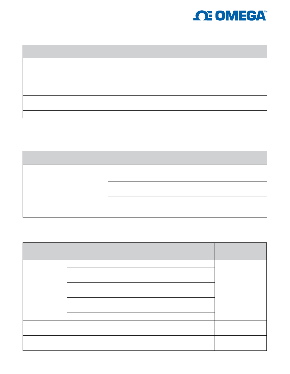
RTD (Requires 10 kΩ Shunt Resistor iNET-R-10K)
1, 3
Absolute Accuracy
RTD (Ω @ 0°C) Measurement Range
(≥100 µSec Averaging Per Point)
±50°C ±0.48°C
-100 to 300°C
100 Ω
-100 to 150°C: ±0.61°C
150 to 300°C: ±0.74°C
-238 to 0°C: ±0.52°C
-238 to 850°C
100 to 850°C: ±1.40°C
500 Ω -100 to 300°C ±0.62°C
1 kΩ -100 to 300°C ±0.64°C
100 Ω -100 to 150°C ±0.44°C
0 to 100°C: ±0.61°C
Thermistor (Requires 10 kΩ shunt resistor iNET-R-10K)
Thermistor (Ω @ 25°C) Measurement Range
10 to 130°C
2252 Ω
e.g. #44004
0 to 70°C ±0.30°C
90 to 250°C ±1.43°C
30 to 250°C
30 to 70°C ±0.16°C
Resistance (Requires iNET-R-x Shunt Resistor)
Measurement
Range
0 to 33 Ω
0 to 100 Ω
0 to 330 Ω
0 to 1 kΩ
0 to 3300 Ω
0 to 10 kΩ
Signal Averaging
Per Point Absolute Accuracy
0.1 mSec ±(0.067% + 0.008 Ω) 2.08K
1.0 mSec ±(0.066% + 0.004 Ω) 0.63K
0 mSec ±(0.072% + 0.028 Ω) 20.20K
1.0 mSec ±(0.067% + 0.005 Ω) 0.75K
0 mSec ±(0.083% + 0.06 Ω) 24.51K
1.0 mSec ±(0.072% + 0.01 Ω) 0.76K
0 mSec ±(0.113% + 0.11 Ω) 24.74K
1.0 mSec ±(0.085% + 0.02 Ω) 0.76K
0 mSec ±(0.114% + 0.40 Ω) 24.74K
1.0 mSec ±(0.091% + 0.10 Ω) 0.76K
0.1 mSec ±(0.131% + 0.10 Ω) 4.27K
1.0 mSec ±(0.122% + 0.10 Ω) 0.76K
1, 3
1, 3
Absolute Accuracy
(≥100 µSec Averaging Per Point)
10 to 30°C: ±0.25°C
30 to 70°C: ±0.17°C
70 to 130°C: ±0.21°C
30 to 170°C: ±0.48°C
170 to 250°C: ±2.24°C
Channel Max
Aggregate Sample
Rate (s/sec/agg) Shunt Resistor
iNet-R-1K
iNet-R-1K
iNet-R-1K
iNet-R-1K
iNet-R-3300
iNet-R-3300
8
Page 9
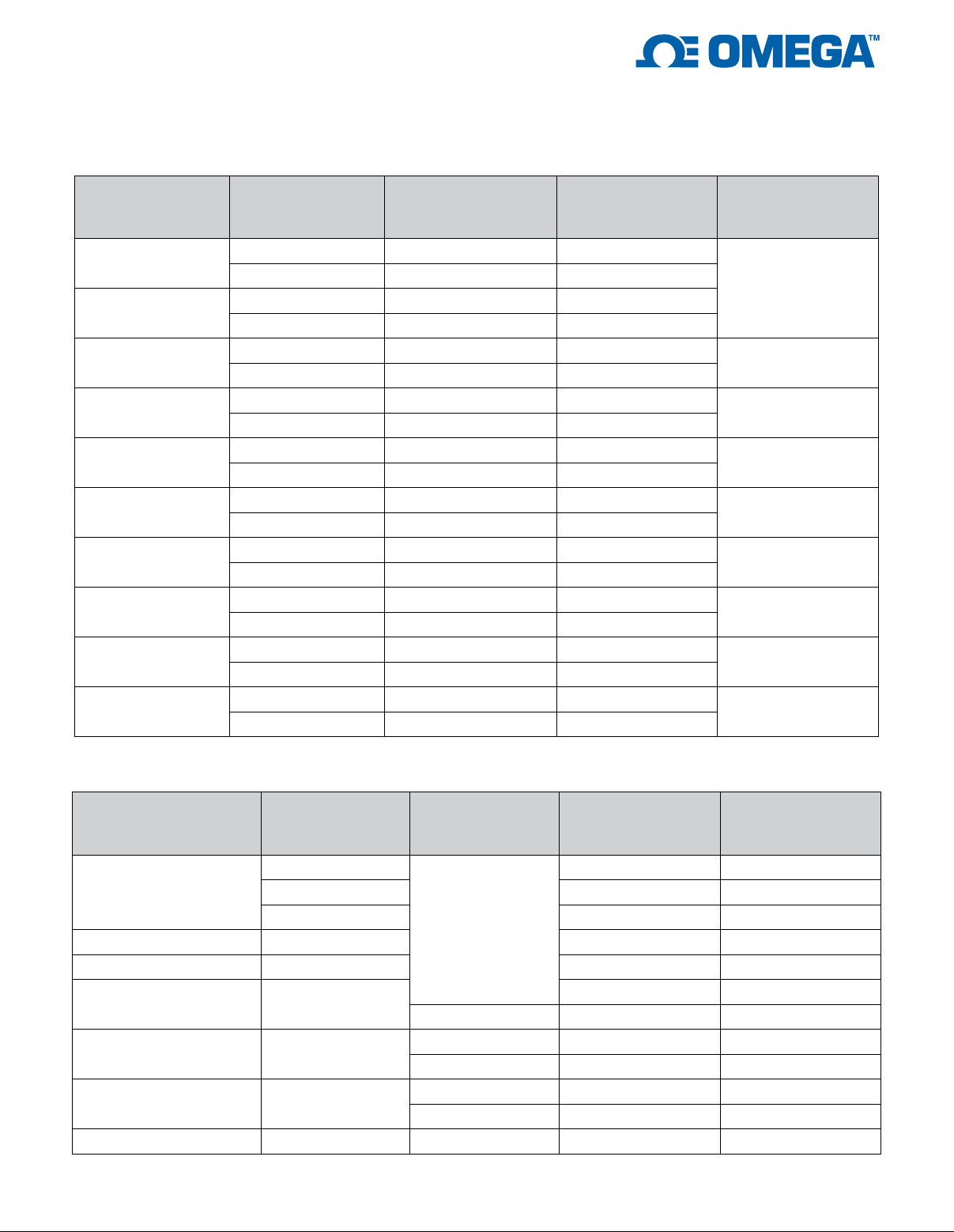
Current (Requires iNET-R-x Shunt Resistor)
Measurement
Range
0 to 24 mA
±24 mA
±12 mA
±2.5 mA
±1.2 mA
±500 uA
±600 uA
±800 uA
±120 uA
±80 uA
Signal Averaging
Per Point Absolute Accuracy
0 mSec ±(0.056% + 6.0 uA) 24.70K
1.0 mSec ±(0.056% + 1.1 uA) 0.76K
0 mSec ±(0.056% + 6.0 uA) 24.70K
1.0 mSec ±(0.056% + 1.1 uA) 0.76K
0 mSec ±(0.056% + 3.1 uA) 23.98K
1.0 mSec ±(0.056% + 0.6 uA) 0.75K
0 mSec ±(0.056% + 0.4 uA) 17.28K
1.0 mSec ±(0.056% + 0.1 uA) 0.74K
0 mSec ±(0.055% + 0.20 uA) 17.17K
1.0 mSec ±(0.055% + 0.04 uA) 0.74K
0.1 mSec ±(0.056% + 0.02 uA) 2.48K
1.0 mSec ±(0.056% + 0.01 uA) 0.67K
0 mSec ±(0.056% + 0.12 uA) 15.02K
1.0 mSec ±(0.056% + 0.02 uA) 0.73K
0.1 mSec ±(0.055% + 0.19 uA) 2.08K
1.0 mSec ±(0.055% + 0.09 uA) 0.63K
0.1 mSec ±(0.058% + 0.007 uA) 2.40K
1.0 mSec ±(0.058% + 0.004 uA) 0.67K
0.1 mSec ±(0.058% + 0.016 uA) 1.92K
1.0 mSec ±(0.058% + 0.008 uA) 0.61K
1, 3
Channel Max
Aggregate Sample
Rate (s/sec/agg) Shunt Resistor
iNet-R-33
iNet-R-120
iNet-R-1K
iNet-R-1K
iNet-R-10K
iNet-R-1K
iNet-R-120
iNet-R-10K
iNet-R-1K
Strain Gage
1
Channel Max
Measurement
Strain Gage
350 Ω (¼ Bridge)
350 Ω (½ Bridge Bend) ±5868 μS ±5.6 μS 1.97K
Range Signal Per Point Absolute Accuracy
±11875 μS
±13.5 μS 1.97K
±24035 μS ±15.5 μS 1.97K
±49258 μS ±22.3 μS 2.02K
0.1 mSec
Aggregate Sample
Rate (s/sec/agg)
350 Ω (½ Bridge Axial) ±8945 μS ±8.5 μS 1.97K
350 Ω (Full Br Bend) ±2934 μS
350 Ω (Full Br Axial I) ±4445 μS
350 Ω (Full Br Axial II) ±4459 μS
1.0 mSec ±0.9 μS 0.62K
0.1 mSec ±2.5 μS 1.97K
1.0 mSec ±1.4 μS 0.62K
0.1 mSec ±2.5 μS 1.97K
1.0 mSec ±1.4 μS 0.62K
±1.6 μS 1.97K
1 kΩ (¼ Bridge) ±11876 μS 0.1 mSec ±10.0 μS 1.88K
9
Page 10
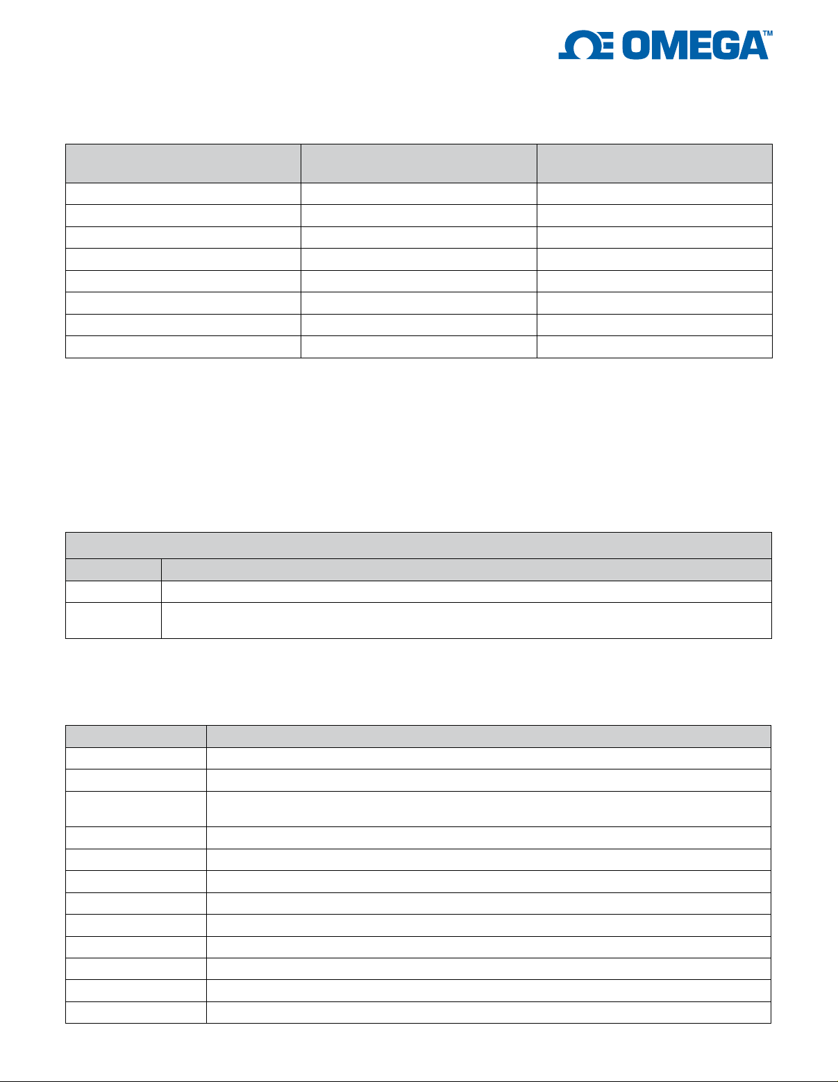
Load Cell
1
Absolute Accuracy
Load Cell Measurement Range
(≥1 mSec Averaging Per Point)
10 Kg (350Ω, 2 mV/V @ MaxKg) 0 to 10 Kg ±0.006 Kg
25 Kg (350Ω, 2 mV/V @ MaxKg) 0 to 25 Kg ±0.015 Kg
100 Kg (350Ω, 2 mV/V @ MaxKg) 0 to 100 Kg ±0.061 Kg
250 Kg (350Ω, 2 mV/V @ MaxKg) 0 to 250 Kg ±0.152 Kg
1000 Kg (350Ω, 2 mV/V @ MaxKg) 0 to 1K Kg ±0.607 Kg
5000 Kg (350Ω, 2 mV/V @ MaxKg) 0 to 5K Kg ±3.037 Kg
100 Kg (500Ω, 2 mV/V @ MaxKg) 0 to 100 Kg ±0.066 Kg
100 Kg (1000Ω, 2 mV/V @ MaxKg) 0 to 100 Kg ±0.083 Kg
1 Absolute Accuracy is specified as a percentage of measured value PLUS a fixed offset. It is the sum of the following errors components, each
in their worst case: Integral Nonlinearity (INL), Differential Nonlinearity (DNL), system noise (ground input, digitize, and see noise), gain/offset
temperature drift, gain/offset time stability drift, gain/offset initial offset error, 4.5nA max leakage current (at 37°C) times user source impedance
error, multiplexor current pump error, and voltage reference temperature/time drift. Noise offset error is modeled as 3 times the Noise RMS value
(99.7%). Absolute Accuracy is the same as Maximum Worst Case error. For Typical error, divide maximum by 2.
These specifications assume 1 year since Factory Calibration and instruNet hardware ambient temperature is between 13 and 33 °C.
Absolute accuracy is shown with both a gain and offset component, where the offset error is independent of the input voltage, and the gain
error is proportional to the input. For example, if you measure 2 Volts and the absolute accuracy specification is ± (1% + 3 mV), then you could
expect ± (1% * 2V + 3 mV) = ±23 mV accuracy.
2 Thermocouple absolute accuracy also includes error from cold junction compensation and 0.2°C iNET-510 screw terminal temperature
change since last auto-calibration.
3 Absolute accuracy also includes error from INET-R-x external shunt resistor self-heating and initial inaccuracy
To Order
Model No. Description
iNET-600
iNET-601
iNET-600 and iNET-601 USB data acquisition modules come complete with USB interface cable, instruNet World software on CD, mating Hd44
female connector, Hd44 cover and hardware assembly kit.
Ordering Example: iNET-601 standalone direct-to-sensor USB data acquisition system, 16SE/8DI voltage inputs, 4 digital I/O, with
electrical isolation.
Accessories
Model No. Description
iNET-510
iNET-511
iNET-512
iNET-iWPLUS
iNET-380
iNET-R-33
iNET-R-120
iNET-R-350
iNET-R-1K
iNET-R-3300
iNET-R-10K
iNET-R-33K
Standalone direct-to-sensor USB data acquisition system, 16SE/8DI voltage inputs, 4 digital I/O
Standalone direct-to-sensor USB data acquisition system, 16SE/8DI voltage inputs, 4 digital I/O,
with electrical isolation
Wiring box with screw terminals
Wiring box with BNC connectors
Strain gage/sensor wiring box with screw terminals (not for thermocouples - use iNET-510
for thermocouple)
InstruNet World Plus software (IW+)
LabVIEW drivers (LabVIEW version ≥4 currently supported on Windows ≥XP)
33 Ω, 8-pack, 0.05%, 5 ppm/°C drift
120 Ω, 8-pack, 0.05%, 5 ppm/°C drift
350 Ω, 8-pack, 0.05%, 5 ppm/°C drift
1000 Ω, 8-pack, 0.05%, 5 ppm/°C drift
3300 Ω, 8-pack, 0.05%, 5 ppm/°C drift
10 kΩ, 8-pack, 0.05%, 5 ppm/°C drift
33 kΩ, 8-pack, 0.05%, 5 ppm/°C drift
10
 Loading...